Article

Balloon Design for Mars, Venus, and Titan Atmospheres

1
Onboard Space Systems, Department of Computer Science, Electrical and Space Engineering, Luleå University of Technology, 981 28 Kiruna, Sweden
2
Atmospheric Science, Department of Computer Science, Electrical and Space Engineering, Luleå University of Technology, 981 28 Kiruna, Sweden
*
Author to whom correspondence should be addressed.
These authors contributed equally to this work.
Appl. Sci. 2020, 10(9), 3204; https://doi.org/10.3390/app10093204
Submission received: 29 October 2019 / Revised: 12 April 2020 / Accepted: 17 April 2020 / Published: 4 May 2020
(This article belongs to the Special Issue Space Technology: Benefit for Earth from Space)

Abstract

:
This paper studies the specifications of balloons for the exploration of bodies with different atmospheric conditions. Three types of balloons, i.e., zero-pressure, super-pressure, and over-pressurized, with four different shapes, i.e., sphere, oblate, prolate, and airship, were analysed. First, the development of a simulation tool is described, which was used for analysing the behaviour of balloons for different exploration missions. Next, the developed software was verified by comparing its output with recorded data from a set of flights at the Esrange Space Center. Based on the simulation results, recommendations are given for different balloon types and shapes for operation on Mars, Venus, and Titan.

1. Introduction

Buoyant aerial vehicles are potential candidates for future space missions, as these vehicles can provide extensive, low-altitude geographical coverage over multi-month time scales with minimal power at low costs on planets and moons with a significant atmosphere [1]. The details of other aerial vehicles that have been suggested for different atmospheric bodies can be found in [2,3,4,5].
In 1986, the Vega mission deployed balloons in Venus atmosphere to demonstrate the technical feasibility of using balloons on other planets for scientific observations [6]. Since then, there has been a number of flagship studies by NASA and ESA which suggest the use of aerial vehicles for atmospheric explorations [7,8,9,10]. In 2009, the Venus Flagship Mission (VFS) study by NASA suggested the use of two helium-filled, super-pressure (SP) balloons for a 30-day mission at an altitude of 55 km for the study of Venus clouds and atmosphere [7]. In the same year, ESA suggested a mission called European Venus Explorer (EVE) [11], which considered a balloon as the primary platform for Venus explorations. Another mission that is currently in the planning phase is Venera-D which includes three elements, i.e., orbiter, lander, and a balloon [12,13]. In the case of Titan, there are three flagship mission studies, namely, Tandem and Enceladus Mission (TANDEM) [8], Titan Explorer Flagship Mission (TEFM) Study [14], and Titan and Saturn System Mission (TSSM) [9], all of which suggest the use of aerial vehicles as a high priority for the mission.
These studies ([7,9,10,12,13,15,16]) suggest a particular aerobot type for the exploratory mission, but only a few of these studies focused on how different aerobot types can add different characteristics to the mission [17]. The type of aerobot that can be deployed to different planets/moons are: zero-pressure (ZP), super-pressure (SP), or over-pressurized zero-pressure (OZP). Zero-pressure (ZP) balloons are those whose internal-external pressure differential is zero; in super-pressure balloons (SP), the pressure of the buoyant gas inside the vehicle exceeds the ambient pressure in an almost uniform manner. An over-pressurized zero-pressure (OZP) balloon is a hybrid which combines the features of both ZP and SP balloons, i.e., first the balloon should be able to handle a higher than ambient pressure and then it should be able to safely achieve float and relieve pressure in excess of the design limits for over-pressure [18]. The different characteristics that these different aerobot types might add to the mission are, for example, an SP aerobot might be more stable on a planet/moon than a ZP aerobot, the mass, volume, and lifetime of different types of aerobots might differ as per the atmosphere of planets/moons, etc. Therefore, it is interesting to study the behaviour of different types of aerobots in different atmospheres as this will help in laying the groundwork of what type of aerobots could be used to fulfil the different mission requirements.
In general, the spherical shape is the preferred shape for any balloon type as the ratio of the volume to surface area, i.e., the balloon efficiency is highest for the sphere shape [19]. However, this ratio might not be the most important factor for balloon operation on different planets/moons as different shapes can complement the balloon mission with other characteristics, for e.g., a mission might demand a faster or slower ascent, or a balloon that can continuously do altitude excursions, etc. Further, it is expected that a balloon with a fineness ratio f much greater or much less than 1 will be unstable as it will not have enough buoyant force for different balloon types. Therefore, it is interesting to study the behaviour of different balloon shapes and types for varying fineness ratio.
Further, there is a need for proper tools for the synthesis and analysis of exploratory robots. A tool that is capable of simulating and evaluating the performance of different types of balloons, taking into consideration different design options, is one of the main requirements for the balloon deployment. There is a number of tools, e.g., THERMTRAJ [20], the Scientific Balloon Analysis Model (SINBAD) [21], and Balloon Ascent [22] developed by NASA, and ACHAB [23] developed by the Italian Space Agency, which have been extensively used for analysing the performance of balloon flights on Earth. However, none of them can simulate the balloons on other planets as they do not have flexibility to provide multiple environment types, and they have tightly coupled balloon and environment models.
Next, Global Aerospace Corporation has developed an advanced balloon performance and analysis tool, called Navajo. This tool aims to advance the state of the art for balloon performance models and assist NASA and commercial balloon designers by providing high-accuracy vertical and horizontal trajectory predictions [24]. It overcomes the drawbacks of other tools, and has other added functionalities, such as simulation of horizontal trajectory, safety analysis capability, and graphical user interface. It is an example of a new, advanced, and modern simulation and analysis tool that enables the development of new balloon and lighter-than-air (LTA) technologies for Earth and planetary applications [25]. However, the full version of Navajo is only available to NASA. For researchers, only the non-Beta test version of the tool is available for purchase. It can simulate zero-pressure balloons within a limited set of environments, and hence it is not useful for detailed analysis of planetary balloons. The Buoyant aerobot design and simulation study (BADS) gives a good insight on planetary aerobots, but the tool itself, as mentioned by the developer, lacks a good stable mathematical core for flight simulation, and hence it is not useful for detailed analysis of planetary balloons [26].
In the last decade, the focus of the ballooning community has been on the improvement of models for flight prediction of stratospheric balloons. Cho et al. [27] studied the influence of infrared radiation on high altitude balloons. Alexander [28] did a numerical study on open atmospheric balloon dynamics to gain qualitative understanding of balloon dynamics in the Earth atmosphere. Xia et al. [29] investigated the transient thermal behaviour of stratospheric Earth balloons at float conditions. Dai et al. [30] analysed the effect of thermal model on performance of SP balloons. Yang et al. [31] presented an improved thermal and vertical trajectory model of stratospheric SP balloons. Lee et al. [32] developed a numerical prediction for the trajectories of scientific balloons while considering various uncertainties. Recently, thermal modelling and analysis of airships have attracted the interest of the research community, and a few examples are [33,34,35]. The above-mentioned works are insightful for the ballooning community, but before implementing and studying the effects of such models for planetary balloon design, a tool needs to be developed, which can facilitate the study of balloons for bodies with different atmospheres. This paper discusses the development of a tool that is capable of simulating balloons in different environments. The paper focuses on the analysis and synthesis of balloons with different types and shapes for Mars, Venus, and Titan.

2. Theoretical Model

The theoretical basis for the simulation tool that is capable of trajectory prediction and performance evaluation of balloons is discussed in this Section. The theoretical model description is based on [22,36,37].

2.1. Planetary Environment

The atmospheric characteristics of the planetary body play an important role in the design of balloons. Examples of the effect of environment include: (a) the atmospheric density determines the size of the balloon; (b) the wind directions affect the trajectory; and (c) the infrared and solar radiation determines the requirements on the strength of the balloon envelope. Other factors that impact the balloon design are: surface albedo, surface thermal inertia, topography, time of year of the flight, atmospheric composition and temperature.
For the design of balloons on different planets/moons, a standard atmospheric profile of the particular body has to be used along with the temperature and diurnal variation, gravity, irradiance, albedo, eccentricity, etc. For the design of a balloon on Mars and Venus, the atmospheric profile data are taken from [38], and the HASI Titan data model [39] is used for Titan. Each of these models reproduces the atmospheric profile of temperature, pressure and air density. Table 1 lists atmospheric parameters for Earth, Mars, Venus, and Titan.

2.2. Air and Gas Properties

The atmospheric density ρ a can be calculated by using the ideal gas law:
ρ a = P a R a T a
Here, P a and T a are the atmospheric pressure and temperature and R a is the specific gas constant of the atmospheric air. The ρ g is the gas density. The dynamic viscosity μ g , conductivity k g , and Prandtl number P r g of the lifting gas are functions of lifting gas temperature T g . The dynamic viscosity can be calculated using the Sutherland’s law:
μ g = μ 0 g · T g T 0 g · T 0 g + S g T g + S g 3 / 2 ,
where the coefficients μ 0 g , T 0 g , and S g depend on the specific gas or atmosphere and can be looked up in tables. Thus, the dynamic viscosity of air can be derived using the same equation but using index ‘ a ’ instead of ‘ g ’. The conductivities for gas and air can be interpolated from tabulated temperature dependences.

2.3. Geometric Properties

While the volume and type of gas play an important role in deciding the amount of mass a balloon can lift, the shape of the balloon has an important role in the aerodynamics and pressure distribution inside the balloon. In this work, we attempted to analyse the behaviour of different shapes for different planet and moon atmospheres. In general, a spherical shape is the preferred shape for any aerobot type as the ratio of volume to surface area (aerobot efficiency) is highest for a sphere shape. In the case of aerobot operation on different planets/moons, this ratio might not be the most important factor as different shapes can complement the mission with varying characteristics, for example, a mission might demand a faster or slower ascent, or an aerobot that can continuously do altitude excursions. When the sphere is deformed by directional scaling, an ellipsoid shape is formed. An ellipsoid is given by the following Cartesian coordinates:
x 2 a 2 + y 2 b 2 + z 2 c 2 = 1
When an ellipsoid is rotated about its principal axis z, then a spheroid is formed with z as the symmetry axis and a = b , the equation can be written as:
x 2 + y 2 a 2 + z 2 c 2 = 1
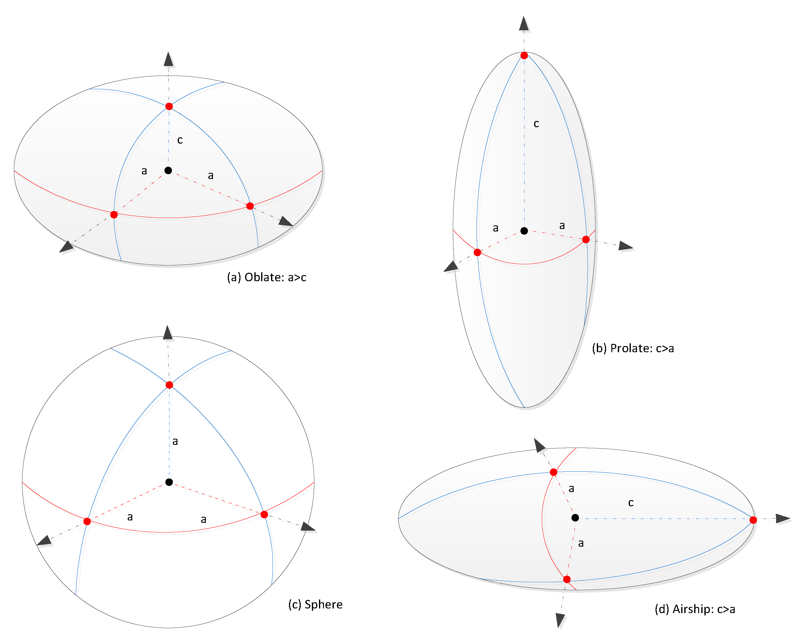
Here, a is the equatorial radius of the spheroid and c is the distance from centre to pole along the axis of symmetry. A spheroid is called an oblate, if c < a (Figure 1a), and it is called a prolate, if c > a (Figure 1b), and if c = a , then it is a sphere (Figure 1c). When a prolate shape is rotated by 90 around the y-axis, it is called an airship (Figure 1d). The ratio of a to c is defined as fineness ratio f in this work. For analysing the performance of oblate shape, the fineness is varied between 2 and 9, and for prolate and airship it is varied between 0.1 and 0.8. Different parameters that are used for simulating these particular shapes are: volume ( π a 2 c ), diameter ( 2 a , or 2 c for airship), surface area A, top area A x y (projected onto x y plane), projected area A x z (projected onto x z plane), height ( 2 c , or 2 a for airship), and effective area A e ( 0.5 ( A x y + A x z ) = 0.5 π a ( a + c ) for all shapes). Figure 1 shows the different shapes, and Table 2 gives the area parameters that depend on the shape.

2.4. Buoyancy

Aerobots work on the principle of buoyancy or Archimedes principle, where the buoyant force is equal to the weight of the displaced fluid. In the case of a balloon, the buoyancy is complicated by the presence of a lighter compressible lifting gas, and so the principle can be described as: the net buoyant force is equal to the weight difference between the displaced air and the lifting gas. This net buoyant force, in the case of a balloon also called gross inflation G I , can be written as
G I = g · V · ( ρ a ρ g ) ,
where g is the planetary acceleration of gravity, V is the volume of the balloon, and the terms g ρ a V and and g ρ g V are the weight of the displaced air, i.e., the gravitational force acting on the displaced air (equal to the total buoyant force as per Archimedes principle), and the weight of the gas inside the balloon, respectively.
The balloon starts ascending if initially G I is larger than the gross weight M gross g , where M gross is the gross mass, i.e., the total mass M t without the mass of the lifting gas ( M gross = M t m g ). While ascending, the lifting gas is cooling adiabatically due to its expanding volume. This adiabatic cooling rate is usually stronger than the atmospheric lapse rate; thus the weight of the displaced atmospheric gas is decreasing. Consequently, both the net buoyant force and the gross inflation are decreasing. The increasing volume reaches the maximum volume V design at some point and the volume expansion comes to a stop. While ascending beyond this point, in the case of ZP balloons, the lifting gas starts venting, and, in the case of SP balloons, the internal gas pressure remains constant, leading to a larger than ambient pressure inside the balloon. In both cases specific buoyancy is further reduced, until, at some particular altitude, neutral buoyancy is achieved, i.e., the gross weight of the balloon system equals G I (or total weight equals the total buoyant force g ρ a V ). This particular altitude is called float altitude and once the balloon reaches this altitude, it floats horizontally in the direction of winds. The maximum design volume may be calculated from the neutral buoyancy condition at the float altitude as:
V design = M t ρ a or
V design = M gross ρ a ρ g
with ρ a at atmospheric temperature and pressure and ρ g at atmospheric temperature and gas pressure (inside the balloon) at the float altitude. Equations (6a) and (6b) are equivalent as the mass of lifting gas required for neutral buoyancy (at the float altitude) is now:
m g = V design · ρ g
However, to guarantee stable ascent to the desired float altitude, a free lift (F) is added, i.e., a lifting capability that is in addition to the required neutral buoyancy. Hence, the amount of lifting gas to be filled can be calculated from Equations (6) and (7) as:
m g = ( 1 + F ) · M gross · ρ g ( ρ a ρ g )
Note, that neither V design nor m g can be calculated directly due to interdependencies. For example, the gross mass, which needs to be known to calculate V design (Equation (6)) depends on V design itself. The size of the balloon, i.e., V design determines the balloon envelope or film mass m f , which is included in the gross mass. Thus Equation (6) must be used in a recursive method to calculate V design . Then m g can be calculated using Equation (8). In this paper, the method of inflating the balloon is not considered, which means that any additional mass required for that, such as the mass of gas tanks, is assumed to be included in the payload mass. Note, that in the case of ZP balloons the additional amount of lifting gas that was added to include free lift will be vented through ducts that do not allow inflation beyond the maximum volume V design . Therefore, the float altitude that was considered in Equation (6b) when calculating V design is reached (and not exceeded).
For SP balloons, Equation (8) is used directly in the iterative process to find m g . The volume V design , needed in the iterative process, is calculated from Equation (6a). This is necessary since in case of SP no gas is vented; therefore, the free lift and increased m g require a larger balloon (as can be seen from Equation (6a), where M t includes the increased m g .

2.5. Equations of Motion

The motion of a balloon can be described by the ordinary differential equations (ODE) that illustrate the time evolving behaviour of the balloon system. The North East Down (NED) coordinate frame is used for the ODEs that describe the horizontal and vertical motion of the balloon system. The balloon vertical acceleration a z is found by summing up the vertical components of applied forces on the system, and can be written as:
m v a z = G I M gross g D z
In Equation (9), the mass m v is the virtual mass and it accounts for the mass of air that is dragged along the balloon. It can be written as: m v = M t + C mass ρ a V , where M t is the total mass of the balloon system, C mass is the virtual mass coefficient and it is taken as 0.5 in this work [37]. M t is the total mass and can be written as: M t = m p + m b + m e + m g . Here, m p is the payload mass, m e is the balloon envelope or film mass, m b is the ballast mass, and m g is the gas mass. The gas mass m g changes due to ducting (i.e., venting at maximum volume), valving, or permeation. In Equation (9), G I is the gross inflation and is defined in Equation (5). The Drag D z in Equation (9) can be calculated using:
D z = 1 2 C D ρ a A x y v rel z 2 ,
where A x y is the area of the balloon projected at a particular time, C D is the drag coefficient, and v rel z is the relative velocity in the z direction. The drag model used in this work is taken from [41]:
C D = 5.4856 · 10 9 · tanh ( 4.3774 · 10 9 / Re ) + 0.0709 · tanh ( 700.6575 / Re ) + 0.3894 · tanh ( 74.1539 / Re ) 0.1198 · tanh ( 7429.0843 / Re ) + 1.7174 · tanh ( 9.9851 / Re + 2.3384 ) + 0.4744 Re < 2 · 10 5
C D = 8 · 10 6 · ( ( Re / 6530 ) 2 + tanh ( Re ) 8 · ln ( Re ) / ln ( 10 ) ) 0.4119 · exp ( 2.08 · 10 43 / ( Re + Re 2 ) 4 ) 2.1344 · exp ( ( ( ln ( Re 2 + 10.7563 ) / ln ( 10 ) ) 2 + 9.9867 ) / Re + 0.1357 · exp ( ( ( Re / 1620 ) 2 + 10370 ) / Re ) 8.5 · 10 3 · ( 2 · ln ( tanh ( tanh ( Re ) ) ) 2825.7162 ) / Re + 2.4795 2 · 10 5 < Re < = 10 6
C D = 0.212546 Re > 10 6
The Reynolds number Re used in Equations (11)–(13) can be defined as:
Re = ρ a · D b · v rel / μ a
The balloon diameter is given by D b and μ a is the atmospheric dynamic viscosity. Further, there are no horizontal forces acting on the balloon except the aerodynamic drag (horizontal winds), and, therefore, the equations of horizontal accelerations are:
M t a x = D x
M t a y = D y

2.6. Envelope Temperature

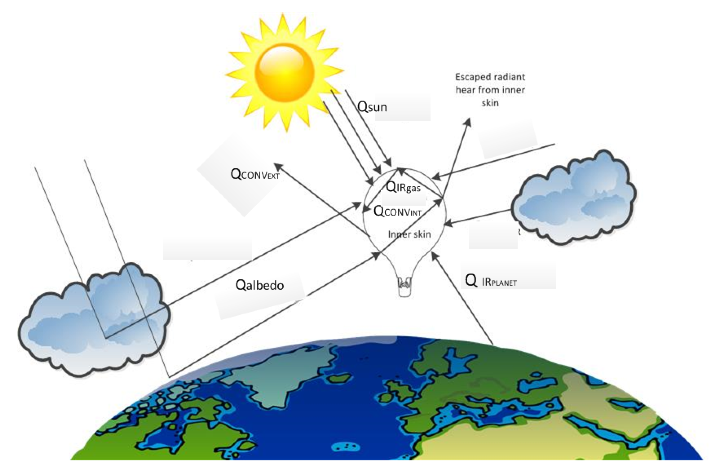
The balloon flight is affected by radiant thermal energy as indicated in Figure 2, which shows involved radiant heat fluxes. The heat transfer model used in this work is from [37].
While the balloon ascends, the gas is expanding and the energy flux impinging the balloon envelope is constantly changing. The differential equation of the balloon envelope temperature T e is:
d T e d t = Q e c e m e ,
where c e is the specific heat capacity of the balloon envelope and Q e is the total heat flux exchanged with the balloon envelope, which can be expressed as the sum of several heat fluxes:
Q e = Q sun + albedo + Q IR planet + Q IR gas + Q conv int + Q conv ext
The first term, Q sun + albedo , accounts for direct solar heat and solar albedo. The term Q IR planet accounts for the net infrared heat input from the planet. Next, Q IR gas accounts for the net infrared heat flux between the gas inside the balloon and the envelope. The two terms Q conv int and Q conv ext account for convective heat exchange with the internal gas and the external air, respectively.
Using the laws of thermodynamics and the Stefan–Boltzmann law, the energies exchanged with the balloon envelope can be listed as follows:
Q e = α e ¯ I 0 ( A e + F bs a s A ) + ϵ e ¯ σ A ( F bs T s 4 T e 4 ) + ϵ ¯ σ A ( T g 4 T e 4 ) + h ge A ( T g T e ) + h ae A ( T a T e )
The effective solar absorptivity of the envelope is α e ¯ and can be calculated using the following formulation:
α e ¯ = α e 1 + τ e ( 1 α g ) 1 r e ( 1 α g ) ,
where α e and τ e are the solar absorptivity and solar transmissivity of the envelope respectively. α g is the solar absorptivity of the lifting gas, and r e is the solar reflectivity of the envelope. Next, in Equation (19), I 0 is the solar constant defined as a flux density measuring the mean solar radiation (solar irradiance) per unit area [37]. A e is the effective surface area. The albedo is dependent on the location of the balloon, time, and the presence of clouds and is given by a s . In the current version of the integrated design and simulation tool the albedo for every planet is a constant number and can be changed by the user.
The term ϵ e ¯ in Equation (19) is the effective infrared emissivity of the envelope and can be calculated using the following expression:
ϵ e ¯ = ϵ e 1 + τ ei ( 1 ϵ g ) 1 r ei ( 1 ϵ g ) ,
where ϵ e is the infrared emissivity of the envelope, τ ei the infrared transmissivity of the envelope, ϵ g the infrared emissivity of the lifting gas, r ei the infrared reflectivity of the envelope, σ the Stefan-Boltzmann constant, and F bs the shape factor from the balloon to the planet, for which in this work the value 0.5 is used for all shapes [26]. Further, T s denotes the effective temperature of the ground surface as seen by the balloon, T a is the atmospheric temperature, and T g is the gas temperature. The convective heat transfer coefficients between the lifting gas and envelope and between the atmosphere and envelope are h ge and h ae , respectively, and can be calculated using the following:
h ge = Nu g k g D b
h ae = Nu a k a D b
Here, Nu a and Nu g denote the Nusselt numbers for the atmosphere and the lifting gas, respectively. More details for calculating the Nusselt numbers can be seen in [23,26,37].

2.7. Gas Temperature

The differential equation of the balloon gas temperature can be written as:
d T g d t = Q g c p g m g g M a T g c p g T a M g v rel z ,
where c p g is the specific heat capacity of the balloon gas, M a and M g are the molar mass of air and gas, respectively. The second term accounts for temperature change due to adiabatic expansion [37]. The first term accounts for heat exchanged with the balloon gas, Q g , which can be written as:
Q g = Q sun + albedo + Q IR planet + Q IR gas + Q conv int
Q g = α g ¯ I 0 ( 1 + a s ) A + ϵ g ¯ σ A ( T s 4 T g 4 ) + ϵ ¯ σ A ( T e 4 T g 4 ) + h ge A ( T e T g )
In this equation, α g ¯ and ϵ g ¯ are the effective solar absorptivity and effective infrared emissivity of the lifting gas, respectively, and can be calculated using:
α g ¯ = α g τ e 1 r e ( 1 α g )
ϵ g ¯ = ϵ g τ ei 1 r ei ( 1 ϵ g ) ,

3. Software Development

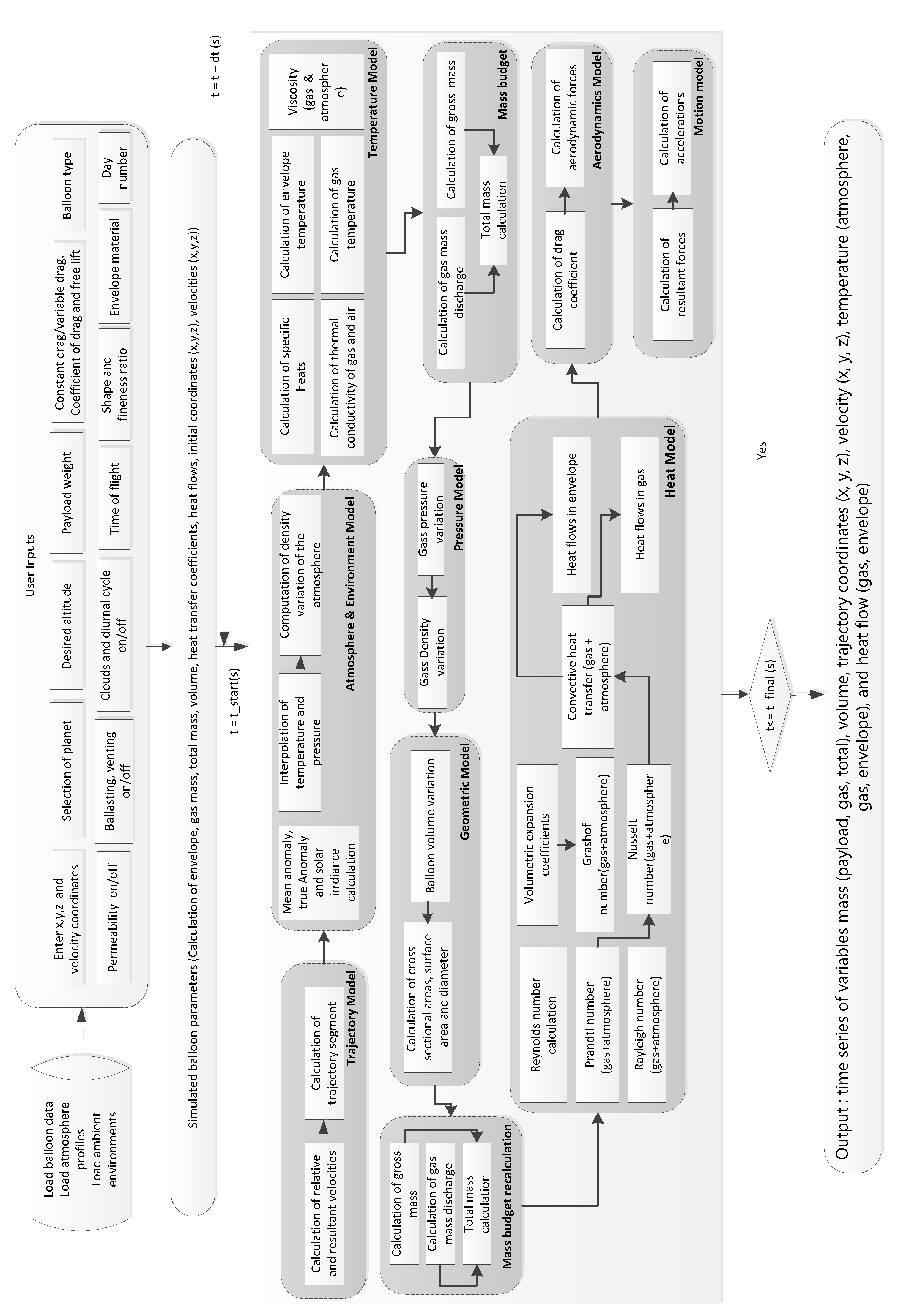
The theoretical model described in Section 2 was implemented in an integrated design and simulation environment developed in MATLAB TM . The tool provides a platform for studying three types of balloons, namely ZP, SP, and OZP, with four different shapes, i.e., sphere, oblate, prolate, and airship. Figure 3 illustrates the top level architecture for the developed environment. The developed tool was verified and validated to identify and investigate discrepancies between simulated results and data from real flights of ZP balloons in the Earth’s atmosphere.
This verification of the developed tool was done by using GPS recorded data of different balloon flights carried out by the Swedish Space Corporation. The data used for verification are from three different types of ZP balloons, a 12,000 m 3 (FL-1) balloon that was flown during autumn, and a 50,000 m 3 (FL-2) balloon and a 1,120,546 m 3 (FL-3) balloon that flew in summer. Table 3 gives the details of the flight specifications for both balloons. The real and simulated flight altitude profiles of these two balloons can be seen in Figure 4.
Both the simulated and the real flights achieved the float altitude at approximately the same time. The overall flight behaviour and estimation of different parameters is fairly consistent with the real flight data. The gas mass, envelope mass, and volume obtained from the simulation tool are also similar to the real flight. The simulated flight altitudes of FL-1, FL-2, and FL-3 have average altitude errors of 868 m, 865 m, and 765 m, respectively, in comparison to the real flight data. This could be due to the uncertainties related to the different parameters of the ascent equations. For example, the cloud cover, albedo, and initial lift gas quantity have significant effects on the ascent rate, and there is some uncertainty in the values of these parameters corresponding to the real flight data, and hence the error. While additional systematic model errors cannot be excluded, it is not possible to claim which of these errors is larger—input errors or model errors. In [42], the author presents a detailed analysis on the effect of various input parameters on the balloon ascent.

4. Balloon Design for Different Atmospheres

This Section illustrates the simulated balloon behaviour for different design options for Venus, Mars, and Titan. The various design specifics for these balloons have been taken from various feasibility studies [14,40,43]. Section 4.1 illustrates the simulated behaviour of ZP, SP, and OZP balloons for Venus. For Mars, Section 4.2 presents only the SP and OZP balloon simulations, as ZP balloons are not feasible. In case of Titan, all three balloon type simulations with different shapes are presented in Section 4.3.

4.1. Balloons on Venus

The wind circulations and high density of the Venusian atmosphere make it an interesting candidate for balloon exploration [7]. The VEGA balloons deployed in the Venusian atmosphere in 1985 as a collaboration between USSR, French, and US scientists were the first planetary exploration balloons [44]. These spherical SP balloons operated for about 2 Earth days at an altitude of 50–54 km over the surface of Venus and succeeded to observe the wind pattern at such altitudes until their batteries were depleted. Since then various studies have suggested the use of balloons for Venus exploration [45].
The main advantage of using SP balloons is their ability to maintain a stable altitude under atmospheric turbulence and diurnal solar flux variations. While various studies have illustrated the importance of spherical SP balloons for Venus [43,46,47], not much is said in the literature about the feasibility of ZP and OZP balloons for Venus explorations. This Section presents a comparative analysis of the three types of balloons (ZP, SP, and OZP) for exploring Venus.
At an altitude of 52–53 km, Venus resembles the atmosphere of Earth except for the presence of sulphuric acid and haze-like clouds. Permanent winds of magnitude 65 m/s to 100 m/s in clockwise direction are common and provide many advantages to balloon flights [48]. To survive the contact with the sulphuric acid, the balloon envelope has to be chosen with utmost care. The Jet Propulsion Laboratory (JPL) has suggested the use of fluoropolymers, PTFE (polytetrafluoroethylene) & PFA (perfluoroalkoxy polymer) as a protective layer on the Mylar film as this combination has extremely low permeability and can cease the effect of sulphuric acid [49]. For deploying the balloon on Venus, aerial deployment is preferred. In [17], the authors suggest that for lifting a 0.31 kg net payload mass (i.e. without gas tank), a balloon would have a diameter of around 0.4 m. For an exploratory balloon on Venus, certain envelope characteristics, payload mass, and float altitude have been suggested in the literature [43,47,50], and on the basis of these studies, the parameters used for simulating the balloon flight on Venus have been chosen and are listed in Table 4.
Figure 5, Figure 6 and Figure 7 illustrate the ascent behaviour of oblate, prolate, and airship shape ZP, SP, and OZP balloons for several fineness ratios. The behaviour of oblate, prolate, and airship ZP balloons can be seen in Figure 5. In the case of oblate shape ZP balloons, with the increase in oblateness (increase in fineness ratio), the cross-sectional area A x y of the balloon increases, and as a result the drag acting on the balloon also increases. Consequently, the ascent speed of the balloon decreases. In the case of prolate shape ZP balloon, with the increase in prolateness (i.e., decrease in fineness ratio), the A x y decreases, as a result the drag acting on the balloon decreases. Hence, the balloon with high prolateness ascends faster than the balloon with low prolateness. For the airship shape balloons, with the increase in prolateness, the A x y increases and as a result, the drag increases and the ascent speed of the balloon decreases.
For the prolate shape ZP cases, balloons with prolateness between 0.1–0.4 reach the float altitude but then start to descend again. While the balloon ascends, the temperature of the lifting gas decreases due to adiabatic expansion at a faster rate than the temperature of the surrounding atmosphere, which follows the atmospheric temperature lapse rate. Initially, this leads to the lifting gas being colder than the atmosphere. However, with increasing temperature difference, convective heat transfer becomes more important. Eventually, at the float altitude, thermal equilibrium is reached. Because of solar heat input, T g may then be higher than the atmosphere, as is the case for the Venus simulations. The state of neutral buoyancy and thermal equilibrium is complex due to all involved heat flows and forces and the balloon oscillations around this equilibrium state. The instability in case of more pronounced prolateness may be due to the increased surface area, affecting the heat flows, and the decreased A x y , reducing the drag. Both effects combined lead to increased balloon speed before and during the oscillations around float altitude, which in turn can cause instability.
Figure 6 and Figure 7 illustrate the behaviour of SP and OZP balloons for the different shapes with varying fineness ratios. Similar to the ZP oblate balloons, both SP and OZP oblate shape balloons achieve stability for different fineness ratios. Also, in the case of prolate shape, unlike ZP, both SP and OZP balloons are able to stay afloat at all the fineness ratios. SP and OZP balloons allow higher than atmospheric pressure, and therefore, have a fixed volume at the float altitude, i.e., the volume does not increase or decrease with a change in gas and atmospheric temperature, and, hence, these balloons tend to stay afloat for long durations, irrespective of the configuration of the shape.
Figure 8 presents the envelope mass and gas mass variation for ZP, SP, and OZP balloons at varying oblateness and prolateness. The envelope mass of ZP and OZP balloons are very similar as the envelope properties for these balloons are the same. The SP balloon envelope mass is heavier in comparison, as the envelope used has higher density in addition to a larger balloon volume required. The envelope and gas mass increase linearly with an increase in oblateness for all three types of balloons and can be seen in Figure 8a. For prolate and airship, the envelope and gas mass decreases linearly as the prolateness decreases towards a spherical shape (Figure 8b). For ZP and OZP to reach the same float altitude as SP, slightly less gas mass is needed.
Next, the behaviour of different shapes of ZP, SP, and OZP balloons were compared with a sphere shape. A fineness factor of 3 was chosen for oblate shape, 0.6 for prolate shape, and 0.4 for airship shape as all three types of balloons are stable at these fineness ratios. Figure 9 presents the ascent speed variation for the three types of balloon and four different shapes. The balloon ascent speed increases or decreases in accordance with the variation in altitude and fluctuates around zero when the balloon reaches the stable altitude. After reaching the stable altitude, the balloon moves in the direction of the wind and only ascends or descends if ballasting and valving operations are applied to the balloon system. The flight behaviour of the different shapes varies. The prolate shape has the highest velocity while the oblate shape has the least velocity, for all three types of balloon. There are almost no altitude excursions for these shapes after the balloon reaches the stable altitude and, hence, the velocity is almost zero.
To summarise the design concept of the balloon on Venus, the following two criteria can be used: mass efficiency and time to reach the float altitude. If one wants to use prolate shape in the case of ZP balloons, then only certain configurations are stable (fineness above 0.3). For SP and OZP balloons, while the flight performance is almost similar for all shapes, the total mass of the balloon system varies. The oblate shape balloons with a fineness ratio above 4 and prolate and airship shape balloons with a fineness ratio below 0.3 are much heavier in comparison to the sphere. If the mission needs the balloon to ascend slowly and have no constraints on the mass of the balloon system, the oblate shape can be a preferred option; if the mission demands a faster ascent, then the prolate shape can be a preferred choice; if the mass efficiency is the major requirement than the spherical balloon of ZP, SP, or OZP can be used.

4.2. Balloons on Mars

The atmosphere on Mars has a low density in comparison to those of Earth and Venus, which makes the balloon flight operation difficult on the surface of Mars. Mars also has extreme temperature variations ( Δ T 100 K and Δ T / T m i n 50 %) which increases the challenges related to the balloon flight. At low altitudes on Mars, the balloon flight is similar to flying in the Earth’s stratosphere as pressure and density are similar, and, therefore, the performance metrics in terms of the balloon material mass per unit area and volume are comparable [50,51]. On Earth, ZP balloons are typically flown at these altitudes, but due to the high temperature variation in day-to-night, these balloons are impractical in the Mars atmosphere, as they have to deploy significant amount of ballast in order to stay afloat, fact that the lifetime of these balloons brief, i.e., few days. This characteristic of ZP balloons makes them unattractive for operation on Mars as they have to carry extra mass, and in addition are not able to collect enough data ‘geographically and temporally’ [52] due to limited lifetime in order to justify the high cost of the mission. The two types of balloons that seem viable options for Mars are the SP and OZP.
Over the years, a number of conceptual and experimental studies have been done for balloon missions on Mars [50,51,53]. In [17], the authors suggest that for lifting a 15.8 kg net payload mass (i.e., without gas tank), a balloon with a diameter of around 8 m would be required. While none of these studies have given a detailed analysis of different shapes for the balloon mission on Mars, they do suggest some important design parameters. Table 5 shows the parameters that will be used for simulating the balloon behaviour on the surface of Mars. Similar to the case of Venus, balloons will be aerially deployed to minimize the risks [52].
Figure 10 presents the behaviour of prolate, oblate, and airship shapes at different fineness ratios for the SP balloons. All three shapes of SP balloons reach the desired float altitude. In the case of oblate shape SP balloons, the time taken by the balloon to reach the float altitude increases with the increase in oblateness (increase in fineness ratio). As the oblateness increases, the cross-sectional area of the balloon increases, so does the drag, and due to the increase in drag, the velocity of the balloon decreases. Therefore, with the increase in oblateness in Figure 10a, the time taken by the balloon to reach the float altitude also increases. The behaviour of the prolate shape SP balloons is illustrated in Figure 10b. With increase in prolateness (decrease in fineness ratio), A x y decreases, which reduces the drag. Consequently the balloon ascends faster, which leads to larger oscillations around the float altitude. In the case of airship (Figure 10c), with the increase in prolateness (decrease in fineness ratio), A x y increases, and, hence, the drag. Therefore, the time taken by the balloon to reach the float altitude increases.
The behaviour of the OZP balloons with varying shape and fineness ratios can be seen in Figure 11. The OZP balloons reach the desired float altitude. The time to reach the stable float altitude for different shapes at varying fineness ratio illustrates a behaviour similar to that of the SP balloon oblate, prolate, and airship shapes. Further, the OZP balloons of a particular fineness ratio ascend faster than the corresponding SP balloons of the same fineness ratio.
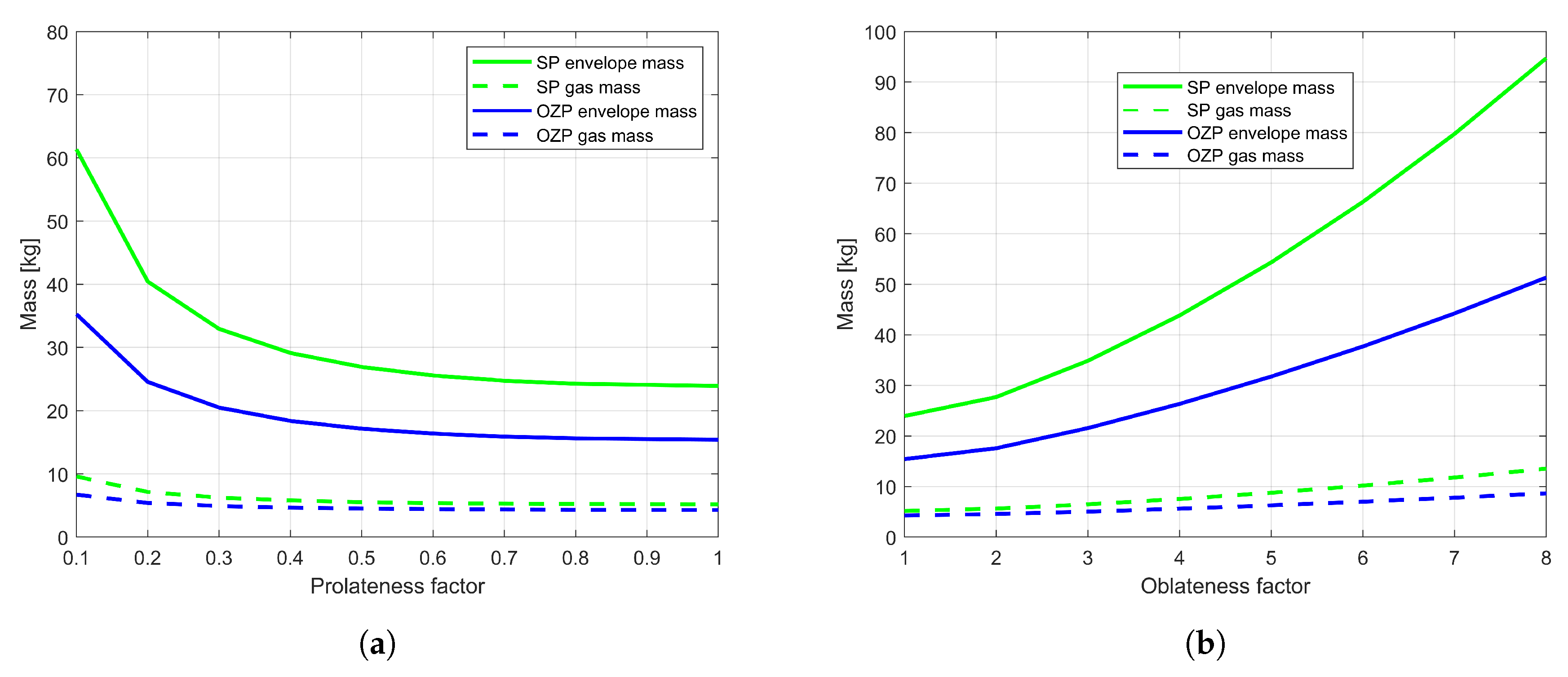
Figure 12 presents the mass characteristics for the SP and OZP balloons of different shapes with varying fineness ratios. The OZP balloons are heavier than the SP ones in terms of both gas and envelope mass. For oblate shape SP and OZP balloons, the mass of both envelope and gas increases with increase in the fineness ratio. The envelope mass of the balloon with oblateness = 8 is almost 3 times that of the balloon with oblateness = 2 for both SP and OZP balloons (Figure 12a). In the case of prolate and airship shapes as the prolateness decreases towards sphere, the envelope mass also decreases. The envelope mass of the balloon with a prolateness of 0.1 is twice that of the balloon with prolateness of 0.8 (Figure 12b). The gas mass for oblate shape increases with an increase in oblateness and for prolate shape it decreases with a decrease in prolateness.
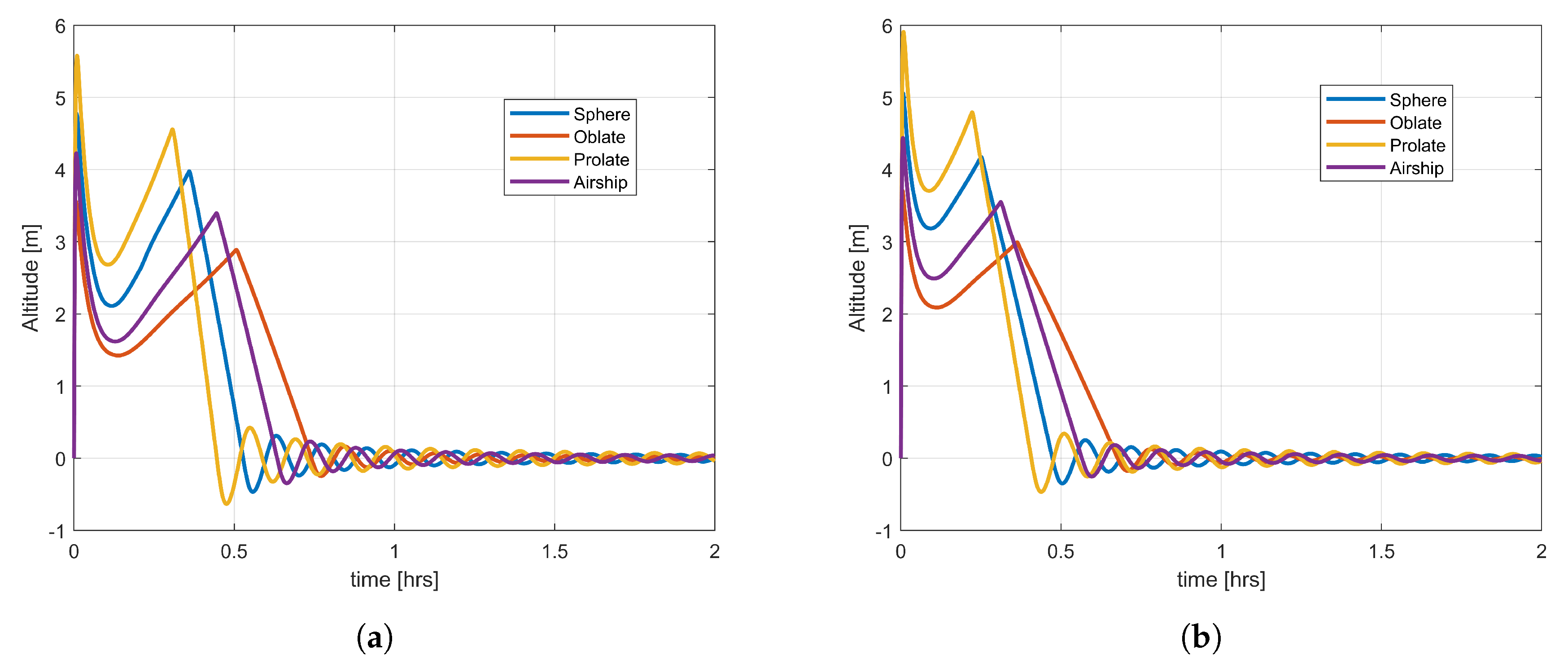
In order to compare the behaviour of different shapes of the SP and OZP balloons with a sphere shape, a fineness factor of 0.4 for airship and 0.4 for prolate and airship, and 4 for oblate shape were used. Figure 13 presents the ascent speed variation of these shapes. Once deployed, it takes almost one hour for different shapes of the SP and OZP balloons to reach the stable altitude. The prolate shape for both SP and OZP balloons has the highest ascent velocity in comparison to that of the other shapes. The OZP balloon shapes have higher ascent speed in comparison to the corresponding shape of the SP balloons. For both SP and OZP different shapes, there are almost no oscillations in velocity once the balloon reaches the stable altitude.
For the balloon mission on Mars, the OZP balloons are in general more mass efficient. For both SP and OZP balloons it is preferred to use the balloons with low oblateness, a low prolateness or sphere. In terms of flight behaviour, the OZP balloons have a faster ascent speed, in comparison to that of the corresponding SP shapes. In terms of flight characteristics depending upon the requirements, all shapes for both OZP and SP balloons can be used, except a highly prolate shape as it ascends and oscillates very fast; therefore, it might be at risk to loose its heat and eventually burst.

4.3. Balloons on Titan

Titan is a unique place in the solar system [54,55]. The Cassini-Huygens mission revealed Titan to be a complex and fascinating world with diverse topographical features, and a methane based hydrological cycle [56]. Since then, buoyant vehicles have gained the recognition that they can provide an outstanding and unmatched means of in-situ exploration on a global scale on the surface of Titan [56].
Titan’s low gravity, thick atmosphere, and Earth like characteristics make it a perfect candidate for exploration using an atmospheric flight. Titan’s air density is 4 times that of the Earth at sea-level, the surface pressure is 1.5 times that of the Earth, and the surface temperature is −93 K. While the air density supports a balloon mission on Titan, the temperature makes it challenging. Too low temperatures can make the material brittle; therefore, the material used for the balloon fabrication on Titan has to be chosen with utmost care. Further, the atmospheric models of aerosols and precipitation indicate methane clouds at 10–35 km of altitude, which suggests that the balloon should be deployed at an altitude below 10 km [57]. On Titan, the near-surface winds are expected to be <1 m/s up to an altitude of a few hundred meters (the planetary boundary layer thickness). At 10 km altitude, the winds are predicted to be around 1.0–2.5 m/s towards East [58], which enables the global coverage of Titan.
Studies suggested three types of balloons, ZP, SP, and Montgolfière for a mission on Titan [14,56]. Montgolfière balloons are a type of ZP balloons, which use heated ambient air instead of helium and hydrogen. The use of OZP balloons on Titan has not been mentioned in the literature. In this paper, the performance of three types of balloons, i.e., ZP, SP, and OZP, with 4 different shapes is analysed. For Titan’s cryogenic environment, use of a radioisotope power source (100 W for a mass of 20–40 kg) is needed for all balloon concepts. Some suggestions have been made regarding the payload mass, the balloon envelope material, and the float altitude in the literature [56,59]; these parameters are used for simulating the behaviour of different types of balloons and shapes on the Titan’s surface. Table 6 summarizes these parameters.
Figure 14, Figure 15 and Figure 16 present the behaviour of oblate, prolate, and airship shapes for ZP, SP, and OZP balloons and varying fineness ratios. The ZP and OZP balloons tend to reach the desired float altitude. The time taken by the ZP and OZP balloons to reach the stable altitude is more than that of the SP ones for similar shape and fineness ratio. The behaviour of the ZP and OZP balloons is similar (at the same shape and fineness ratio); the time taken by these balloons to reach the float altitude is also similar (Figure 14 and Figure 16). For oblate and airship shape of ZP, SP, and OZP, as the oblateness (increase in fineness ratio) and prolateness (decrease in fineness ratio) increases the amount of time it takes the balloon to get stabilized at float altitude increases. In the case of prolate shape, with the increase in prolateness, the time to reach the stable float altitude decreases.
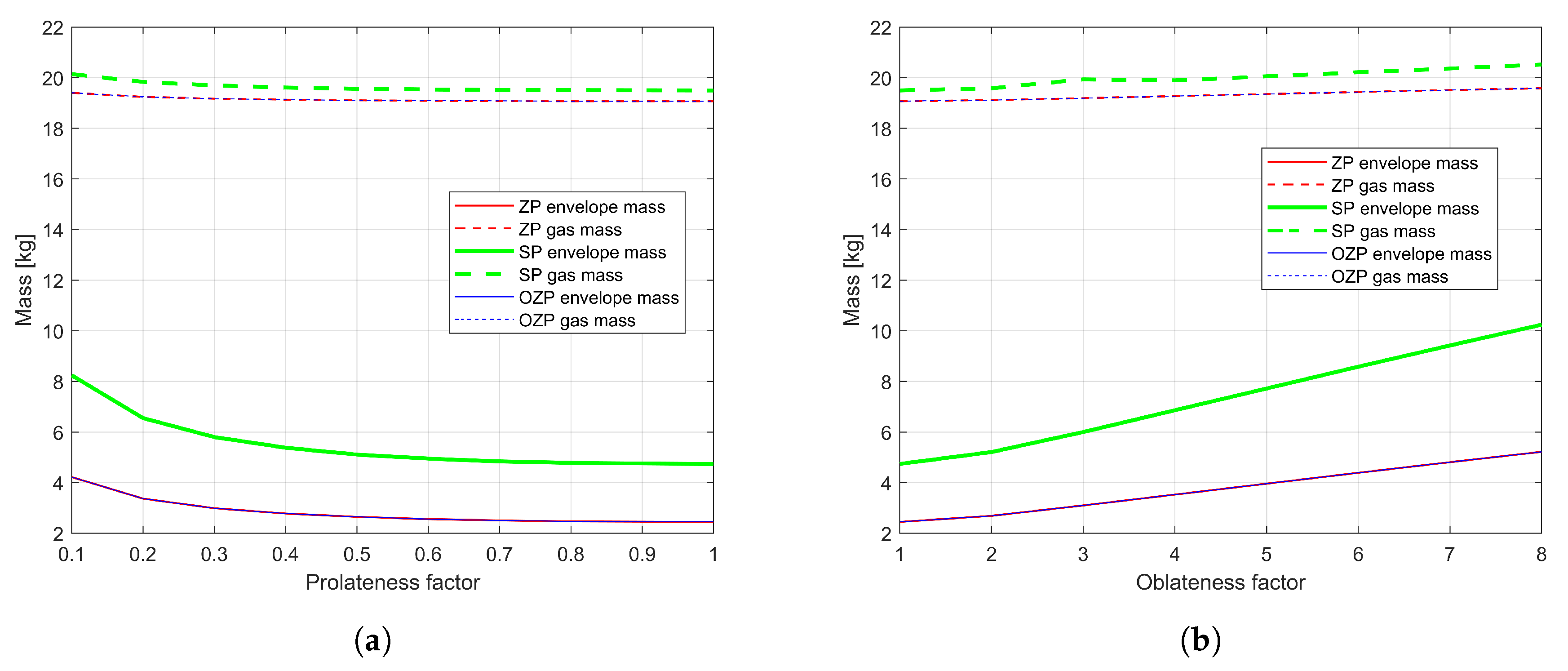
Figure 17 illustrates the envelope and gas mass variation for the ZP, SP, and OZP balloons at varying fineness ratio. The envelope and gass mass of the ZP and OZP balloons are similar and less than that of the SP ones at different fineness ratios. In the case of different shapes, and an increase in prolateness and oblateness, the envelope and gas mass increase. The oblate shape balloons are, in general, heavier than both prolate and airship in terms of both gas and envelope mass as can be seen in Figure 17b.
Next, the sphere-shape balloons are compared with the oblate, prolate and airship shapes for the ZP, SP, and OZP balloons. The fineness factor used for comparison is 3 for oblate, 0.4 for airship and 0.6 for a prolate shape. Figure 18 presents the ascent speed for all balloon types and shapes. The ascent speed of the ZP and OZP balloons is similar. The prolate-shape balloons for all three types of them have higher velocity, while the oblate shape has the least. The SP balloons for all shapes have velocity lower than the corresponding shapes of the ZP and OZP balloons.
To summarize, for the balloon mission on Titan, the OZP and ZP balloons seem to be more mass efficient than the SP balloons, which means that the latter balloons need almost twice the amount of gas. The envelope masses of ZP and OZP are similar, while the ZP balloons are slightly heavier. In the case of shape, it is preferred to use the prolate, airship, and oblate shapes with low prolateness, and oblateness factor. Balloons with high prolateness and high oblateness are heavier in comparison to a sphere. In terms of the ascent speed, if high ascent speed is desired, then the prolate shape could be a good choice; if low ascent speed is required then the oblate shape can be used.
5. Conclusions

This paper described the performance of various design options for balloons on Mars, Venus, and Titan. A simulation tool was designed, developed, verified, and validated for investigating various parameters of the exploratory balloons. The performance of the different balloon types and shapes was compared, and suitable options were identified for each mission. For the Venus mission, the shape configuration is important for the balloon to stay afloat, and the choice of shape is very much dependent on the mission requirements. In the case of Mars, the shape configuration does not matter for SP and OZP balloons in terms of stable altitude. For the balloon mission on Titan, the shape configuration does not matter as different shapes tend to stay afloat. In general, if the mission demands a fast ascent to the float altitude, then a prolate shape should be the preferred, and if slow ascent is the requirement, then an oblate shape should be preferred. For all three atmospheric bodies, the OZP balloons are preferred as they are more mass efficient than the SP ones and can stay afloat much longer in comparison to the ZP balloons.

Author Contributions

Following is the summary of contributions of authors. Conceptualization, K.G.; methodology, software, investigation, formal analysis, K.G. and T.K.; writing—original draft preparation, K.G.; writing—review and editing, K.G. and T.K.; supervision, project administration, T.K. All authors have read and agreed to the published version of the manuscript.

Funding

This research was funded by the Graduate School of Space Technology at Luleå University of Technology, Space for Innovation and Growth (RIT), Swedish National Space Agency (SNSA), and SSC.

Acknowledgments

The authors would like to thank Reza Emami for his technical feedback on the Introduction Section.

Conflicts of Interest

The authors declare no conflict of interest.

Nomenclature

Latin Letters
Asurface area of balloon/spheroid
aequatorial radius of a spheroid
A e effective area of balloon ( 0.5 ( A x y + A x z ) )
a s albedo
a x and a y acceleration of balloon in x and y directions
A x y top area of balloon (projected onto x y plane)
A x z area of balloon as projected onto x z plane
a z vertical acceleration of balloon
bone of the three radii of an ellipsoid, see Equation (3)
cdistance from centre to pole along the axis of symmetry of a spheroid
C D drag coefficient
c e specific heat capacity of balloon envelope
C mass virtual mass coefficient
c p g specific heat capacity of the balloon lifting gas
D b balloon diameter
D x and D y aerodynamic drag in x and y directions caused by horizontal winds
D z drag experienced by balloon
Ffree lift factor
ffineness ratio (ratio of a to c)
F bs shape factor from the balloon to the planet
gplanetary acceleration of gravity
G I gross inflation (net buoyant force)
h ae convective heat transfer coefficients between the envelope and atmosphere
h ge convective heat transfer coefficients between the lifting gas and envelope
I 0 solar constant (solar irradiance per unit area)
k a conductivity of atmospheric air
k g lifting gas conductivity
M a molar mass of air
m b ballast mass
m e mass of balloon envelope
M g molar mass of the lifting gas
m g mass of lifting gas
M gross gross mass ( M t m g )
m p payload mass
M t total mass of balloon
m v virtual mass (accounting for mass of air dragged along the balloon)
Nu a Nusselt number for the atmosphere
Nu g Nusselt number for the lifting gas
P a atmospheric pressure
P r g lifting gas Prandtl number
Q conv ext convective heat exchange with the external air
Q conv int convective heat exchange with the internal gas
Q e total heat flux exchanged with the balloon envelope
Q g heat exchanged with the balloon lifting gas
Q IR gas net infrared heat flux between the gas inside the balloon and the envelope
Q IR planet net infrared heat flux from the planet to the balloon
Q sun + albedo direct solar heat and solar albedo
R a specific gas constant of the atmospheric air
Re Reynolds number
r e solar reflectivity of the balloon envelope
r ei infrared reflectivity of the balloon envelope
S a Sutherland temperature of atmospheric air
S g Sutherland temperature of lifting gas
T 0 a reference air temperature in Sutherland’s law
T 0 g reference temperature of lifting gas in Sutherland’s law
T a atmospheric temperature
T e balloon envelope temperature
T g lifting gas temperature
T s effective temperature of the ground surface as seen by the balloon
Vballoon volume
V design maximum balloon volume
v rel z vertical speed of balloon
x , y , z Cartesian coordinates, see Equations (3) and  (4)
Greek Letters
α parameter used to calculate the area of a spheroid, see Table 2
α e solar absorptivity of the balloon envelope
α e ¯ effective solar absorptivity of the balloon envelope
α g solar absorptivity of the lifting gas
α g ¯ effective solar absorptivity of the lifting gas
ϵ e infrared emissivity of the balloon envelope
ϵ e ¯ effective infrared emissivity of the balloon envelope
ϵ g infrared emissivity of the lifting gas
ϵ g ¯ effective infrared emissivity of the lifting gas
μ 0 a reference dynamic viscosity of air at T 0 a
μ 0 g reference dynamic viscosity of lifting gas at T 0 g
μ a atmospheric dynamic viscosity
μ g lifting gas dynamic viscosity
ρ a atmospheric density
ρ g lifting gas density
σ Stefan-Boltzmann constant
τ e solar transmissivity of the balloon envelope
τ ei infrared transmissivity of the balloon envelope

References

  1. Elfes, A.; Hall, J.L.; Kulczycki, E.A.; Clouse, D.S.; Morfopoulos, A.C.; Montgomery, J.F.; Cameron, J.M.; Ansar, A.; Machuzak, R.J. Navigation and Perception for an Autonomous Titan Aerobot. In Proceedings of the AIAA SPACE 2007 Conference & Exposition, Long Beach, CA, USA, 18–20 September 2007; p. 6266. [Google Scholar]
  2. Jaroszewicz, A.; Sąsiadek, J.; Sibilski, K. Modeling and simulation of flapping wings entomopter in Martian atmosphere. In Aerospace Robotics; Sąsiadek, J., Ed.; Springer: Berlin/Heidelberg, Germany, 2013; pp. 143–162. [Google Scholar]
  3. Gonzales, A.A.; Corpus, C.J.; Hall, D.W.; Parks, R.W. Development of a useful mars airplane exploration concept at NASA/ames research center. In Proceedings of the 6th Mars Society Conference, League City, TX, USA, 14–17 August 2003. [Google Scholar]
  4. Lorenz, R. A Review of Balloon Concepts for Titan. J. Br. Interplanet. Soc. 2008, 61, 2–13. [Google Scholar]
  5. Landis, G.; Colozza, A.; LaMarre, C. Atmospheric flight on Venus. In Proceedings of the 40th AIAA Aerospace Sciences Meeting & Exhibit, Reno, NV, USA, 14–17 January 2002; p. 819. [Google Scholar]
  6. Kremnev, R.; Linkin, V.; Lipatov, A.; Pichkadze, K.; Shurupov, A.; Terterashvili, A.; Bakitko, R.; Blamont, J.; Malique, C.; Ragent, B.; et al. VEGA balloon system and instrumentation. Science 1986, 231, 1408–1411. [Google Scholar] [CrossRef] [PubMed]
  7. Bullock, M. Venus Flagship Mission Study; NASA: Greenbelt, MD, USA, 2009.
  8. Coustenis, A.; Atreya, S.; Balint, T.; Brown, R.; Dougherty, M.; Ferri, F.; Fulchignoni, M.; Gautier, D.; Gowen, R.; Griffith, C.; et al. TandEM: Titan and Enceladus mission. Exp. Astron. 2009, 23, 893–946. [Google Scholar] [CrossRef] [Green Version]
  9. Coustenis, A.; Lunine, J.; Matson, D.; Hansen, C.; Reh, K.; Beauchamp, P.; Lebreton, J.P.; Erd, C. The Joint NASA-ESA Titan Saturn System Mission (TSSM) Study. In Proceedings of the Lunar and Planetary Science Conference, The Woodlands, TX, USA, 23–27 March 2009; Volume 40, p. 1060. [Google Scholar]
  10. Cutts, J.; Hall, J.; Kolawa, G. Exploration of Mars, Venus and Titan with Planetary Aerobots: A pathway of Flight Readiness. In Proceedings of the 2000 IEEE Aerospace Conference proceedings, Big Sky, MT, USA, 18–25 March 2000. [Google Scholar]
  11. Chassefière, E.; Korablev, O.; Imamura, T.; Baines, K.; Wilson, C.; Titov, D.; Aplin, K.; Balint, T.; Blamont, J.; Cochrane, C.; et al. European Venus Explorer: An in-situ mission to Venus using a balloon platform. Adv. Space Res. 2009, 44, 106–115. [Google Scholar] [CrossRef]
  12. Zasova, L. Future Venus exploration: Mission Venera-D. In Proceedings of the 40th COSPAR Scientific Assembly, Moscow, Russia, 2–10 August 2014; Volume 40. [Google Scholar]
  13. Kremic, T. Venera-D: Technology Implications; NASA: Greenbelt, MD, USA, 2016.
  14. Lockwood, M.K.; Leary, J.C.; Lorenz, R.; Waite, H.; Reh, K.; Prince, J.; Powell, R. Titan Explorer Flagship Mission Study; Public Report by the Johns Hopkins University Applied Physics Laboratory: Baltimore, MD, USA, 2008. [Google Scholar]
  15. Fink, W.; Dohm, J.M.; Tarbell, M.A.; Hare, T.M.; Baker, V.R. Next-generation robotic planetary reconnaissance missions: A paradigm shift. Planet. Space Sci. 2005, 53, 1419–1426. [Google Scholar] [CrossRef]
  16. Fink, W.; Tarbell, M.A.; Furfaro, R.; Powers, L.; Kargel, J.S.; Baker, V.R.; Lunine, J. Robotic test bed for autonomous surface exploration of Titan, Mars, and other planetary bodies. In Proceedings of the 2011 IEEE Aerospace Conference, Big Sky, MT, USA, 5–12 March 2011; pp. 1–11. [Google Scholar]
  17. Schulze-Makuch, D.; Dohm, J.M.; Fairén, A.G.; Baker, V.R.; Fink, W.; Strom, R.G. Venus, Mars, and the ices on Mercury and the Moon: Astrobiological implications and proposed mission designs. Astrobiology 2005, 5, 778–795. [Google Scholar] [CrossRef] [Green Version]
  18. Simpson, J. Overpressurized zero pressure balloon system. In Proceedings of the International Balloon Technology Conference, Albuquerque, NM, USA, 8–10 October 1991; p. 3671. [Google Scholar]
  19. Grass, L. Superpressure Balloon for Constant Level Flight; Technical Report; Air Force Cambridge Research Labs: Hanscom AFB, MA, USA, 1962. [Google Scholar]
  20. Horn, W.; Carlson, L.A. Thermtraj: A Fortran Program to Compute the Trajectory and Gas Film Temperatures of Zero Pressure Balloons; NASA STI/Recon Tech. Rep. N; NASA: Greenbelt, MD, USA, 1983; Volume 83.
  21. Raque, S.; Robbins, E. Recent developments in the SINBAD balloon vertical performance model. In Proceedings of the 32nd Aerospace Sciences Meeting and Exhibit, Reno, NV, USA, 10–13 January 1994; p. 517. [Google Scholar]
  22. Farley, R.E. BalloonAscent: 3-D simulation tool for the ascent and float of high-altitude balloons. AIAA 2005, 7412, 2005. [Google Scholar]
  23. Palumbo, R.; Russo, M.; Filippone, E.; Corraro, F. ACHAB: Analysis code for high-altitude balloons. In Proceedings of the AIAA Atmospheric Flight Mechanics Conference and Exhibit, South California, CA, USA, 20–23 August 2007; p. 6642. [Google Scholar]
  24. Pankine, A.A.; Heun, M.K.; Nguyen, N.; Schlaifer, R.S. NAVAJO: Advanced software tool for balloon performance simulation. In Proceedings of the 17th ESA Symposium on European Rocket and Balloon Programmes and Related Research, Sandefjord, Norway, 30 May–2 June 2005; Volume 590, pp. 451–455. [Google Scholar]
  25. Pankine, A.A.; Heun, M.K.; Schlaifer, R.S. Advanced balloon performance simulation and analysis tool. In Proceedings of the AIAA’s 3rd Annual Aviation Technology, Integration Operations (ATIO) Tech, Denver, CO, USA, 17–19 November 2003; Volume 6741. [Google Scholar]
  26. Van Dosselaer, I. Buoyant Aerobot Design and Simulation Study: BADS, 2014; Technical University of Delft: Delft, The Netherlands, 2014. [Google Scholar]
  27. Cho, C.; Raque, S.M. Influence of the infrared radiation on a high altitude scientific balloon. In Proceedings of the AIAA Aerospace Sciences Meeting & Exhibit, Reno, NV, USA, 14 January 2002. [Google Scholar] [CrossRef]
  28. Alexander, P. A numerical study of open atmospheric balloon dynamics. Phys. Fluids 2003, 15, 3065–3078. [Google Scholar] [CrossRef] [Green Version]
  29. Xia, X.L.; Li, D.F.; Sun, C.; Ruan, L.M. Transient thermal behavior of stratospheric balloons at float conditions. Adv. Space Res. 2010, 46, 1184–1190. [Google Scholar] [CrossRef]
  30. Dai, Q.; Fang, X.; Li, X.; Tian, L. Performance simulation of high altitude scientific balloons. Adv. Space Res. 2012, 49, 1045–1052. [Google Scholar] [CrossRef]
  31. Yang, X.; Zhang, W.; Hou, Z. Improved Thermal and Vertical Trajectory Model for Performance Prediction of Stratospheric Balloons. J. Aerosp. Eng. 2013, 28, 04014075. [Google Scholar] [CrossRef]
  32. Lee, Y.; Yee, K. Numerical Prediction of Scientific Balloon Trajectories While Considering Various Uncertainties. J. Aircr. 2016. [Google Scholar] [CrossRef]
  33. Yao, W.; Lu, X.; Wang, C.; Ma, R. A heat transient model for the thermal behavior prediction of stratospheric airships. Appl. Therm. Eng. 2014, 70, 380–387. [Google Scholar] [CrossRef]
  34. Wu, J.; Fang, X.; Wang, Z.; Hou, Z.; Ma, Z.; Zhang, H.; Dai, Q.; Xu, Y. Thermal modeling of stratospheric airships. Prog. Aerosp. Sci. 2015, 75, 26–37. [Google Scholar] [CrossRef]
  35. Shi, H.; Song, B.; Yao, Q.; Cao, X. Thermal performance of stratospheric airships during ascent and descent. J. Thermophys. Heat Transf. 2009, 23, 816. [Google Scholar] [CrossRef]
  36. Carlson, L.A.; Horn, W. New thermal and trajectory model for high-altitude balloons. J. Aircr. 1983, 20, 500–507. [Google Scholar] [CrossRef]
  37. Yajima, N.; Imamura, T.; Izutsu, N.; Abe, T. Engineering Fundamentals of Balloons. In Scientific Ballooning; Springer: New York, NY, USA, 2009; pp. 15–75. [Google Scholar]
  38. Colozza, A.; Shahinpoor, M.; Jenkins, P.; Smith, C.; Isaac, K.; DalBello, T. Solid state aircraft concept overview. In Proceedings of the 2004 IEEE NASA/DoD Conference on Evolvable Hardware, Seattle, WA, USA, 26 June 2004; pp. 318–324. [Google Scholar]
  39. Yelle, R.; Strobel, D.; Lellouch, E.; Gautier, D. Engineering models for Titan’s atmosphere. In Huygens: Science, Payload and Mission; Springer: Dordrecht, The Netherlands, 1997; pp. 243–256. [Google Scholar]
  40. Ball, A.; Garry, J.; Lorenz, R.; Kerzhanovich, V. Planetary Landers and Entry Probes; Cambridge University Press: Cambridge, UK, 2007. [Google Scholar]
  41. Barati, R.; Neyshabouri, S.A.A.S.; Ahmadi, G. Development of empirical models with high accuracy for estimation of drag coefficient of flow around a smooth sphere: An evolutionary approach. Powder Technol. 2014, 257, 11–19. [Google Scholar] [CrossRef]
  42. Garg, K. Autonomous Navigation System for High Altitude Balloons. Ph.D. Thesis, Luleå Tekniska Universitet, Luleå, Sweden, 2019. [Google Scholar]
  43. Nishimura, J.; Hinada, M.; Yajima, N.; Fujii, M. Venus balloons at low altitudes. Adv. Space Res. 1994, 14, 61–71. [Google Scholar] [CrossRef]
  44. Sagdeev, R.; Linkin, V.; Blamont, J.; Preston, R. The VEGA Venus balloon experiment. Science 1986, 231, 1407–1409. [Google Scholar] [CrossRef] [PubMed]
  45. Gilmore, M.; Collins, G.; Crumpler, L.; Cutts, J.; Head, J., III; Nock, K.; Parry, M.; Yingst, R. Investigation of the application of aerobot technology at Venus. Acta Astronaut. 2005, 56, 477–494. [Google Scholar] [CrossRef] [Green Version]
  46. Hall, J.L.; Yavrouian, A. Pinhole effects on Venus superpressure balloon lifetime. AIAA Pap. 2013, 1292, 26–28. [Google Scholar]
  47. Hall, J.; Fairbrother, D.; Frederickson, T.; Kerzhanovich, V.; Said, M.; Sandy, C.; Ware, J.; Willey, C.; Yavrouian, A. Prototype design and testing of a Venus long duration, high altitude balloon. Adv. Space Res. 2008, 42, 1648–1655. [Google Scholar] [CrossRef]
  48. Kerzhanovich, V.; Balaram, J.; Campbell, B.; Cutts, J.; Gershman, R.; Greeley, R.; Hall, J.; Klaasen, K.; Zimmerman, W.; Hansen, D. Venus aerobot multisonde mission: Atmospheric relay for imaging the surface of venus. In Proceedings of the IEEE Aerospace Conference Proceedings, Big Sky, MT, USA, 25 March 2000; Volume 7, pp. 485–491. [Google Scholar]
  49. Yavrouian, A.; Plett, G.; Yen, S.; Cutts, J.; Baek, D. Evaluation of materials for Venus aerobot applications. In Proceedings of the International Balloon Technology Conference, Norfolk, VA, USA, 28 June–1 July 1999; p. 3859. [Google Scholar]
  50. Kerzhanovich, V.V.; Cutts, J.A.; Hall, J.L. Low-cost balloon missions to Mars and Venus. In Proceedings of the European Rocket and Balloon Programmes and Related Research, Sankt Gallen, Switzerland, 2–5 June 2003; Volume 530, pp. 285–291. [Google Scholar]
  51. Hall, J.L.; Pauken, M.; Kerzhanovich, V.V.; Walsh, G.J.; Fairbrother, D.; Shreves, C.; Lachenmeier, T. Flight test results for aerially deployed mars balloons. In Proceedings of the AIAA Balloon Systems Conference, Reston, VA, USA, 23 May 2007; pp. 21–24. [Google Scholar]
  52. Hall, J.L.; Pauken, M.T.; Kerzhanovich, V.V.; Walsh, G.J.; Kulczycki, E.A.; Fairbrother, D.; Shreves, C.; Lachenmeier, T. Mars Balloon Flight Test Results. In Proceedings of the AIAA Balloon Systems Conference, Seattle, WA, USA, 4–7 May 2009. [Google Scholar]
  53. Nock, K.T.; Balaram, J.; Heun, M.K.; Smith, I.; Gamber, T. Mars 2001 Aerobot/Balloon System Overview. In Proceedings of the International Balloon Technology Conference, San Francisco, CA, USA, 3–5 June 1997. [Google Scholar]
  54. Furfaro, R.; Lunine, J.I.; Elfes, A.; Reh, K. Wind-based navigation of a hot-air balloon on Titan: A feasibility study. In Proceedings of the Conference on Space Exploration Technologies, Orlando, FL, USA, 17–18 March 2008. [Google Scholar] [CrossRef]
  55. Elliott, J.O.; Lunine, J.; Spilker, T.; Loenz, R.; Reh, K. Titan Montrogiere mission study. In Proceedings of the Outer Planets Assesment Group Meeting, Pasadena, CA, USA, 4–5 May 2006. [Google Scholar]
  56. Hall, J. A Survey of Titan Balloon Concepts and Technology Status. In Proceedings of the 19th AIAA Lighter-Than-Air Systems Technology Conference, Norfolk, VA, USA, 20–22 September 2011. [Google Scholar]
  57. Strobel, D.F.; Atreya, S.K.; Bézard, B.; Ferri, F.; Flasar, F.M.; Fulchignoni, M.; Lellouch, E.; Müller-Wodarg, I. Atmospheric structure and composition. In Titan from Cassini-Huygens; Springer: New York, NY, USA, 2010; pp. 235–257. [Google Scholar]
  58. Garg, K.; Mooij, E. Autonomous Navigation of a Balloon over Saturn’s Moon Titan. In Proceedings of the AIAA Guidance, Navigation, and Control Conference, San Diego, CA, USA, 4–8 January 2016; p. 0887. [Google Scholar]
  59. Hall, J.L.; Jones, J.; Kerzhanovich, V.; Lachenmeier, T.; Mahr, P.; Pauken, M.; Plett, G.; Smith, L.; Van Luvender, M.; Yavrouian, A. Experimental results for Titan aerobot thermo-mechanical subsystem development. Adv. Space Res. 2008, 42, 1641–1647. [Google Scholar] [CrossRef]
Figure 1. Oblate, prolate, sphere, and airship shapes of balloons.
Applsci 10 03204 g001
Figure 2. Radiant heat fluxes affecting the balloon flight. This figure is inspired from [23,32,37].
Applsci 10 03204 g002
Figure 3. Simulation architecture for balloon ascent estimation. The modules which constitute the physical simulation are shown together with their interlinked data connections as well as the databases, inputs, and outputs.
Applsci 10 03204 g003
Figure 4. Altitude variation of real and simulated flights for three types of balloons which were launched from Esrange Space Centre: (a) 12,000 m 3 (FL-1); (b) 50,000 m 3 (FL-2); (c) 1,120,546 m 3 (FL-3).
Applsci 10 03204 g004
Figure 5. Altitude variation of the ZP balloons for different shapes with varying fineness ratio f in order to find the stable fineness ratio on Venus: (a) oblate (f: 2–8) (b) prolate (0.1–0.8) (c) airship (0.1–0.8).
Applsci 10 03204 g005
Figure 6. Altitude variation of the SP balloons for different shapes with varying fineness ratio f in order to find the stable fineness ratio on Venus (a) oblate (f: 2–8) (b) prolate (0.1–0.8) (c) airship (0.1–0.8).
Applsci 10 03204 g006
Figure 7. Altitude variation of the OZP balloons for different shapes with varying fineness ratios f in order to find the stable fineness ratio on Venus (a) oblate (f: 2–8) (b) prolate (0.1–0.8) (c) airship (0.1–0.8).
Applsci 10 03204 g007
Figure 8. Mass variation of different balloon types at varying fineness ratio on Venus (a) Airship and Prolate (b) Oblate. Note that the lines for ZP gas mass and OZP gas mass are superimposed, as well as the lines for ZP envelope mass and OZP envelope mass.
Applsci 10 03204 g008
Figure 9. Ascent speed variation of different balloon types at particular fineness ratio (a) Zero pressure (b) Super pressure (c) Over-pressurized zero pressure. A fineness ratio of 3 is chosen for oblate shape, 0.6 for prolate shape, and 0.4 for airship shape.
Applsci 10 03204 g009
Figure 10. Altitude variation of the SP balloons for different shapes with varying fineness ratios f in order to find the stable fineness ratio on Mars (a) oblate (f: 2–8) (b) prolate (0.1–0.8) (c) airship (0.1–0.8).
Applsci 10 03204 g010
Figure 11. Altitude variation of the OZP balloons for different shapes with varying fineness ratios f in order to find the stable fineness ratio on Mars (a) oblate (f: 2–8) (b) prolate (0.1–0.8) (c) airship (0.1–0.8).
Applsci 10 03204 g011
Figure 12. Mass variation of different balloon types at varying fineness ratio on Mars (a) airship and prolate (b) oblate.
Applsci 10 03204 g012
Figure 13. Ascent speed variation of different balloon types at a particular fineness ratio on Mars (a) SP (b) OZP. A fineness ratio of 0.4 for airship and 0.4 for prolate and airship, and 4 for oblate shape is used.
Applsci 10 03204 g013
Figure 14. Altitude variation of the ZP balloons for different shapes with varying fineness ratios f in order to find the stable fineness ratio on Titan oblate (a) (f: 2–8) (b) prolate (0.1–0.8) (c) airship (0.1–0.8).
Applsci 10 03204 g014
Figure 15. Altitude variation of the SP balloons for different shapes with varying fineness ratios f in order to find the stable fineness ratio on Titan (a) oblate (f: 2–8) (b) prolate (0.1–0.8) (c) airship (0.1–0.8).
Applsci 10 03204 g015
Figure 16. Altitude variation of the OZP balloons for different shapes with varying fineness ratios in order to find the stable fineness ratio on Titan (a) oblate (f: 2–8) (b) prolate (0.1–0.8) (c) airship (0.1–0.8).
Applsci 10 03204 g016
Figure 17. Mass variation of different balloon types at varying fineness ratios on Titan (a) airship and prolate (b) oblate. Note that the lines for ZP gas mass and OZP gas mass are superimposed, as well as the lines for ZP envelope mass and OZP envelope mass.
Applsci 10 03204 g017
Figure 18. Ascent speed variation of different balloon types at a particular fineness ratios (a) ZP (b) SP (c) OZP balloons. The fineness ratio used for comparison is 3 for oblate, 0.4 for airship and 0.6 for prolate shape.
Applsci 10 03204 g018
Table 1. Planetary atmospheric environment parameters for Earth, Venus, Mars, and Titan. Data from [40].
ParametersEarthMarsVenusTitan
Acceleration of gravity, g ( g Earth )10.370.90.14
Main atmospheric gasN 2 CO 2 CO 2 N 2
Surface temperature (K)29023073592
Surface pressure (atm)1.00.0067921.4
Surface air density (kg m 3 )1.20.015644.9
Solar flux at the upper atmosphere (W m 2 )1300700320013
Solar flux near the surface (W m 2 )6007005∼ 1
Diurnal temperature variations near the surface,<1030–50<0.3<1
δ T/T (%)
Winds in lower atmosphere (m s 1 )5–205–201–3∼1
Table 2. The area parameters of different shapes. The surface area A is a function of a, c, and  α , where  α is a function of f that depends on the shape.
ShapeSurface Area A α Cross-Sectional Areas
A xy A xz
Sphere 4 π a 2 - π a 2 π a 2
Prolate 2 π a 2 + c 2 α tan ( α ) arccos( 1 / f ) π a 2 π a c
Oblate 2 π a 2 + c 2 artanh ( sin α ) sin ( α ) arccos ( f ) π a 2 π a c
Airship 2 π a 2 + c 2 α tan ( α ) arccos ( f ) π a c π a 2
Table 3. Flight parameters.
ParameterFL-1FL-2FL-3
Payload (kg)159.22891189.6
Free lift (%)121012
Altitude (m)27,20033,60040,000
Day of Year289166196
Local launch time (24 h)8:1511:1501:00
Solar Absorptivity0.0240.0240.024
Solar Transmissivity0.9160.9160.916
Solar Emissivity0.1340.1340.134
Infrared Transmissivity0.8660.8660.866
Table 4. Venus aerobot parameters. Parameters are based on [43,47,50].
Film area density (g/m 2 ) = 176 (ZP & OZP)= 200 (SP)
Payload mass (kg) = 50Gas = Helium
Strength (kN/m) = 71Elongation (%) = 7.0
Solar absorptivity = 0.17Infrared emissivity = 0.56
Permeability = ∼ 0Deployment altitude (km) = 49
Float Altitude (km) = 55Thickness (mm) = 0.25
Over-pressure (Pa) = 7000 (SP), 500 (OZP)Drag coefficient = Variable
Diurnal cycle = YesTime step (s) = 1
Start day of mission =1 (224.68 days on Venus)
Venting & Ballast (kg) = NoFree lift (%) = 12
Table 5. Mars aerobot parameters. Parameters are based on [50,51,53].
Film area density g/m 2 = 12 (OZP) 16 (SP),Transmissivity = 0.885
Solar absorptivity = 0.07Material strength (kN/m) = 2.8
Permeability = ∼ 0Elongation = 4
Thickness = 0.132 × 10 4 Payload mass = 20 kg
Deployment altitude = 4 kmDesired float altitude = 9 km
Ballast & Venting = NoGas = Helium
Drag coefficient = VariableOver-pressure Pa = 48 (SP), 10 (OZP)
Diurnal cycle = NoFree lift = 16%
Start day of the mission = 1 (686.98 days on Mars)Time step = 1 s
Table 6. Titan aerobot parameters. Parameters are based on [56,59].
Film area density = 50 g/m 2 (ZP, OZP)= 94 g/m 2 (SP)
Thickness = 0.0012Permeability coefficient = 0.006
Tensile strength (N/m) = 9100Elongation = 10
Transmissivity = 0.85Absorptivity = 0.16
Payload weight = 100 kgDeployment altitude = 5 km
Float altitude = 9 kmBalloon type = SP, ZP, OZP
Over-pressure (Pa) = 8000 (SP), 200 (OZP)
Ballast & Venting = NoFree lift = 12 %
Drag coefficient = VariableDiurnal cycle = Yes
Start day of the mission = 1 ( 10759 days on Titan)Time step = 1 s