Featured Application
This study investigated a new method to generate a fault-tolerant gait of a hexapod robot. The adjustment measure is put forward to improve the stability margin. As a gait generation method, the research of the robot on complex terrain can be completed in the future.
Abstract
In some hazardous or inaccessible applications, such as earthquake rescue, as a substitute for mankind, robots are expected to perform missions reliably. Unfortunately, the failure of components is difficult to avoid due to the complexity of robot composition and the interference of the environment. Thus, improving the reliability of robots is a crucial problem. The hexapod robot has redundant degrees of freedom due to its multiple joints, making it possible to tolerate the failure of one leg. In this paper, the Fault-Tolerant Tripod (F-TT) gait dealing with the failure of one leg is researched. The Denavit–Hartenberg (D-H) method is exploited to establish a kinematic model for the hexapod robot, the Jacobian matrix is analyzed, and it is proved that the body can be controlled when three legs are supported. Then, an F-TT gait phase sequence planning method based on a stability margin is established, and a method to improve stability is proposed. The trajectory for the center of gravity (COG) and foot is studied. Finally, a simulation model and prototype robot experiments are developed, and the effectiveness of the proposed method is verified.
1. Introduction
With the rapid development of robot technology, autonomous mobile robots have been widely studied. Multi-legged robots have high stability and environment adaptability compared with wheeled or crawler robots since they do not require consecutive contacts between the foot and ground [1]. Although most of the inspiration for robot design and motion planning comes from insects [2], robots are not yet as flexible as insects. Legged robots are almost always applied in a structured environment while insects are faced with a more complex variable environment. Currently, significant achievements have been made in the research of robots in a normal state in terms of structure, gait, stability, and energy consumption [3]. Through phase coordination, tripod gait, tetrapod gait, wave gait, etc., have been realized. An adaptive gait that can be applied on irregular terrain also has come into reality through a central pattern generator (CPG) network [4,5]. Moreover, the Walknet Controller is a robust, decentralized controller that incorporates findings from the behavior of stick insects for gait coordination of multi-legged robots [6]. In recent years, it has been developed into different versions through expansions [7].
However, greater robustness and reliability are expected for robots to enhance environmental adaptability, such as fault-tolerance ability after failure. In the unstructured environment, it is highly likely for robots to suffer from component failure. Nevertheless, little attention has been devoted to machine malfunction, such as the failure or damage affecting actuators, sensors, or leg structures. Hexapod robots have excellent joint redundancy compared to a quadrupedal robot, so has superior fault tolerance potentiality. Some exceptional conditions, such as broken legs and overturned bodies, have captured scholars’ attention. The Walknet Controller mentioned above was expanded to tolerate amputation, for the loss of one or two legs, by implementing additional inter-leg connections [8]. In addition, finite state automata (FSA) were used by M. L. Liu to analyze the attitude transformation of the robot during normal operation and fault operation [9]. An organic computing method, specifically self-organization, was demonstrated to provide the hexapod with fault tolerance in unforeseen situations [10]. However, these studies relate to control. Regarding fault-tolerance gait analysis, J. Yang conducted a detailed motion analysis of the hexapod when joint locked failure occurred. First, he derived fault-tolerant quadruped periodic gaits with a fault stability margin over the perfectly even terrain of the hexapod [11], then extended it to a Follow-The-Leader (FTL) gait on uneven roads [12]. Furthermore, the FTL gait was applied in post-failure walking, having the advantages of both fault-tolerance and terrain adaptability [13]. X. L. Ding discussed the stability, fault tolerance, turning ability, and terrain adaptability of rectangular hexapod and symmetric hexapod robots; the static stability of different fault-tolerant gaits were also analyzed [14]. Based on behavior research of insects, he proposed the self- recovery method, Sidewise-Self-Recovery (SSR), of a hexagonal robot [15]. However, only overturning of the robot was taken into consideration. Further, F. Gao and his team undertook a significant amount of research in this field. They deduced a fault tolerant criterion of a single broken leg and all leg fault combination types were analyzed using this criterion [16]. Residual mobility was analyzed using the screw theory in the case of a partial actuator fault, and a motion planning method based on a fault tolerance Jacobian matrix was proposed [17,18]. Currently, with the development of artificial intelligence, some scholars have begun to use the method of machine learning or reinforcement learning to generate the walking gait of the six legged-robot with a leg injury. Antoine Cully created a new technology to create a detailed high-performance behavior space map using the Gauss process model of machine learning, and an intelligent trial-and-error algorithm was introduced that can allow the robot to adapt to the environment successfully, including with an injured, broken, or missing leg [19]. The Reset-free Trial-and-Error (RTE) algorithm was explored by K. Chatzilygeroudis, connecting with a probabilistic model to learn how to correct the outcome of each action of the damaged robot [20]. However, their research needs to train the robot in advance to create a detailed map of the space of high-performing behavior, which not only requires a large amount of calculation and storage space, but also has high requirements for hardware.
Until recently, there has been a lack of knowledge around generating the locomotion sequence of a hexapod with a broken leg. Fault-tolerance gait planning remains scarce, and particularly for the gait generation mechanism of the continuous tripod gait. Furthermore, it is also hard to find a method to improve stability based on kinematics. The purpose of this paper is to expand the method of Fault-Tolerant Tripod (F-TT) gait generation. We preliminarily focus on the gait sequence and improvement of the stability margin. Leg failure in this paper refers to a fault in which one leg loses its ability to translate and rotate, and has no capability to support the body of the hexapod robot. The advantage of this continuous tripod gait is that it has higher locomotion velocity, which helps to maintain the fast movement ability of the hexapod robot.
The structure of this paper is organized as follows. Definitions of robot gait are introduced, and the robot structure and kinematic model are established in Section 2. In Section 3, the F-TT gait sequence planning method and the method to improve the stability margin are studied, and their application under two different fault conditions are presented. In Section 4, the trajectory planning of the center of gravity (COG) and the foot is discussed. In Section 5, the simulations and experiments are developed. Some concluding remarks are provided in Section 6.
2. The Modeling of Hexapod Robot
2.1. General Definition of Robot Gait
Robot gait refers to the way that a robot moves its legs regularly in the process of motion. When a robot is walking, legs support the weight of the body and make it move in the walking direction. Different gaits can be distinguished by the order and phase of the transfer leg. Gait parameters [21] are defined as follows.
- Support phase and transfer phase: the state of legs supported on the ground is called the support phase, and the state of legs lifting in the air is called the transfer phase.
- Locomotion period : the duration required for legs to complete one transfer phase and one support phase, including transfer phase period and support phase period , .
- Duty factor : the ratio of the support phase period to the locomotion period; the value range is , .
- Leg phase : relative position of a leg in a locomotion period at the time of lifting.
- Stride : the distance that the center of gravity (COG) of the robot moves in a locomotion period.
- Stroke : the distance that the leg moves from the previous landing point to the next in the transfer phase.
Moreover, to provide an effective evaluation index for the locomotion of robot, a variety of stability evaluation indexes have been proposed, such as longitudinal stability margin (LSM) [22] and energy stability margin (ESM) [23]. However, the static stability margin (SSM) is versatile when the motion velocity is not high. The stability margin represents the margin from the current equilibrium state to the instability state of the robot, which is represented by the minimum vertical distance between the projection point of the COG on the foot support plane and the boundary of the support polygon [24], as shown in Figure 1.
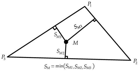
Figure 1.
The definition of static stability margin (SSM).
When the support polygon is a triangle, the projection point of the COG on the support plane is , and the stability margin can be calculated by the following equation:
2.2. Structure of the Hexapod Robot
The design of hexapod robot is based on the body structure and locomotion characteristics of insects. It is composed of six legs with the same structure connected to the body which is composed of two hexagonal plates. Legs are arranged symmetrically on the left side (numbered 1, 2, 3) and right side (numbered 4, 5, 6). Each leg has three revolving joints—coxa joint, femur joint and tibia joint—connecting three segments of the limb—coxa, femur and tibia.
In order to describe the robot quantitatively with a mathematical model, a series of coordinate systems need to be established. A world coordinate system is established to describe the locomotion route of the robot, denoted by the symbol . Then the body coordinate and reference coordinate systems of leg links are established, denoted by the symbols and (i=1,2,3,4,5,6), respectively. Coordinate systems attached to the coxa joint (), femur joint (), and tibia joint () of leg i are established for each joint. The simplified hexapod model and coordinate systems are shown in Figure 2.
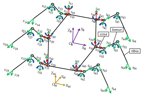
Figure 2.
The simplified prototype of hexapod and coordinate systems.
2.3. Kinematics Model
Kinematics analysis is the basis of gait planning and attitude control of a hexapod robot. Kinematics studies all geometric and time parameters related to motion. To complete the kinematic analysis of the robot, the first problem is to describe the robot parametrically. Based on standard Denavit–Hartenberg (D-H) notation [25,26], the hexapod leg link can be described as in Table 1.

Table 1.
Denavit–Hartenberg (D-H) parameters of a hexapod leg link.
In Table 1, is the link length, is link twist, is the offset, is the joint angle.
The homogeneous transformation matrix describes the relationship of a point in the different coordinate systems. The homogeneous transformation matrix from the foot end coordinate system to the reference coordinate system can be obtained by:
where .
The reference coordinate of leg i can be expressed in the body coordinate frame as given in the following equation:
where is the angle between and , , and is the position of origin in coordinate .
The position of the foot end of leg i in the body coordinate can be obtained by forward kinematics, as shown in Equation (4):
where , , are the expression of the foot end in .
The inverse kinematics maps the relationship between Cartesian coordinates and the joint angle. The joint angles of the hexapod robots are calculated using:
where .
As a parallel system, the complete configuration of hexapod robot can be determined by:
where represents the joint angle of the leg i, and is the under-actuated passive degrees of freedom of the hexapod body, which represents the displacement and angle of the body in three directions of the world coordinate system. and can be regarded as connected by a virtual manipulator with six degrees of freedom, while can be regarded as six under-actuated passive virtual degrees of freedom variables of the manipulator. It can be seen that the motion state of the hexapod robot in is actually determined by the 18 leg joints and the position and attitude of the body.
The velocity of leg i in the world coordinate system can also be connected with the velocity of the joint angle of the robot through the Jacobian matrix; the relationship is:
If the velocity of any foot end is given, the velocity in joint space can be obtained by:
The Jacobian matrix of the foot end of leg i can be expressed by:
where represents the part of Jacobian matrix related to leg i, and represents the part related to body posture.
The Jacobian matrix related to leg i can be obtained by the partial derivative of Equation (4). Give the result as follows:
where , , .
A transformation is needed for to transform to the world coordinate system:
The Jacobian matrix of the foot end is also affected by the passive degree of freedom of the body. In the passive degree of freedom, the influence of body displacement is linear, while the attitude is affected by the configuration of leg i, so it can be expressed as follows:
Although the body has no corresponding drive to achieve the movement, by imposing certain restrictions on the foot end, the movement of body can be represented by the leg joints.
represents the constrained degrees of freedom of the foot end, and the Jacobian matrix is . According to Equation (9), the Jacobian matrix of any foot end contains the parts corresponding to the joint and the part corresponding to the body. For a support foot of the robot, its displacement and velocity can be considered as 0, that is , so:
where .
Equation (14) can be derived from Equation (13).
where , is the pseudoinverse of .
When the movement of one foot is constrained, , the motion of passive degrees of freedom is not completely eliminated. Only when and the rank of matrix is 6, does Equation (14) have a unique solution, and the state of the body can be determined by the configuration leg joints. When a hexapod robot has three legs in contact with the ground, the displacement of the three supporting legs is constrained (i.e., ), and the is 6. The movement of the body can be completely determined by the joints of the supporting legs. Therefore, it is necessary to have at least three legs as support legs to realize control of the robot body.
3. Planning Method of F-TT Gait
3.1. Analysis of Support Polygon
In the practical application of a hexapod robot, leg failure could be caused by the failure of a driving device or power transmission equipment, or by impact. The relationship between the relative position of the fault leg and the fault tolerance of the hexapod robot is analyzed using the support triangle in the tripod gait, which is the design principle to determine the relative position of the support leg in the fault tolerance walking process of the hexapod robot. Figure 3 shows all six possible support triangles for a hexapod robot.

Figure 3.
Six kinds of support triangles. (a) The triangle formed by legs on one side, (b) The triangle formed by two front legs and a middle leg, (c) The triangle formed by the front and rear leg on one side and the middle leg on the other side, (d) The triangle formed by two rear legs and a front leg, (e) The triangle formed by two middle legs and a front leg, (f) The triangle formed by the front and middle leg on one side and the rear leg on the other side.
In the case of Figure 3a,b, the COG is outside the support triangle, the stability margin value is negative, and the hexapod cannot maintain stability; in Figure 3c, the support triangle is composed of three legs separated one by one, and the COG is at the center of the triangle with the best stability, which is expected for support as much as possible. In Figure 3d–f, the support triangles pass through the COG, which is a critical state. However, the stability margin can be increased by stability improvement measures, so these support triangles are reasonable.
3.2. Phase Sequence Planning of F-TT Gait
Based on the theory of the supporting triangle in Section 3.1, the gait phase sequence is planned in this section. As shown in Figure 4, because of the symmetry of the robot, the influence of a single leg fault on the leg distribution of a hexapod robot can be divided into two categories: one is that any one of the middle legs is damaged; the other is that any one of the front or rear legs is damaged. For these two kinds of faults, a unified gait description equation is established.
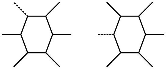
Figure 4.
Two forms of one leg failure of a hexapod robot.
Some new symbols are defined in Table 2.

Table 2.
Symbolic representation.
The F-TT gait equation is based on the tripod gait of the non-fault hexapod robot. Gait function for walking machines with n legs is defined as Equation (15):
The F-TT gait phase equation is given by:
where is the phase, is the duty factor, and the subscript is the symbol of the corresponding leg.
The process of F-TT gait motion is divided into three stages. Five legs in good conditions are divided into three groups. Each time, one group is used in the transfer phase and the rest in the support phase. However, since one leg is broken, another leg needs to swing twice in the motion. The application of the F-TT gait planning equation in two kinds of fault situations will be elucidated.
3.2.1. F-TT Gait in Leg 1 Fault State
During the locomotion process of a hexapod robot, the foot lifts from the ground and takes a step forward in the transfer phase, and contacts the ground to support the body in the support phase. Based on the F-TT gait phase sequence planning equation, the F-TT gait phase sequence diagram of the hexapod robot in the case of a leg 1 fault is obtained, as shown in Figure 5. The shadow parts represent the support phase, and the blank parts represent the transfer phase.
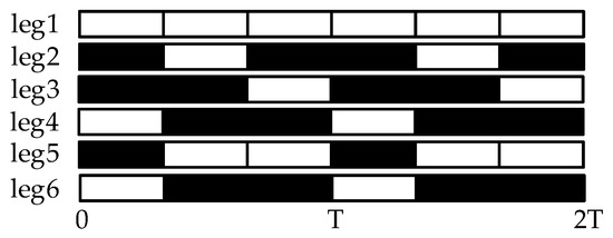
Figure 5.
Phase sequence table of F-TT gait in leg 1 fault state.
The movement process is divided into three steps, as shown in Figure 6. The dotted line in the figure indicates that the leg is in the transfer phase, the dot-dash line indicates a broken leg, the solid line indicates a normal leg in the support phase, the red point is the COG position of the robot, and the blue triangle indicates the stable area formed by the support legs. When the COG is in the support area, the hexapod can be regarded as stabile, otherwise it will tend to topple.
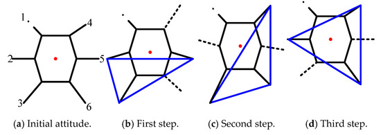
Figure 6.
Transfer order of legs in fault tolerant tripod gait in leg 1 fault state.
In the first process, legs 4 and 6 are lifted up to swing forward, legs 2, 3, and 5 are in the support state to push the body forward, and the robot posture is transformed from Figure 6a,b.
In the second step, legs 4 and 6 touch down, leg 2 is lifted up to swing forward, leg 5 is raised to swing forward at a slower speed, and legs 3, 4, and 6 support the body. Meanwhile, the robot is moved forward passively, and the attitude of hexapod changes from Figure 6b,c.
In the third process, leg 2 touches down, leg 5 continues to transfer forward while leg 3 is lifted to swing forward, legs 2, 4, and 6 are supporting legs, pushing the robot body to move forward, and the attitude of robot changes from Figure 6c,d.
After the above three processes, the robot completes a period of the F-TT gait movement under the fault condition of leg 1. In fact, the postures in Figure 6a,d are the same, because after a period of motion, the robot returns to the initial motion posture.
3.2.2. F-TT Gait in Leg 2 Fault State
Based on the phase and the duty factor of the F-TT gait equation, the gait phase sequence diagram of the hexapod in the case of a leg 2 fault is obtained, as shown in the Figure 7. The F-TT gait locomotion process of the hexapod robot in the leg 2 fault state is shown in Figure 8; the dotted line in the figure indicates a leg in the transfer phase, the dot-dash line indicates a broken leg, and the solid line indicates a normal leg in the support phase.
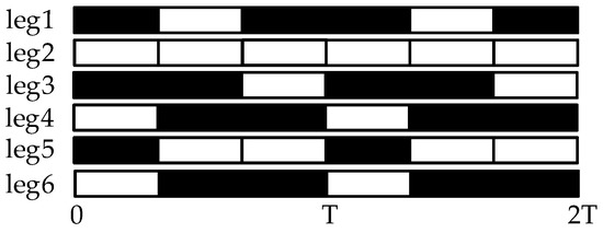
Figure 7.
Phase sequence table of fault tolerant tripod gait in leg 2 fault state.
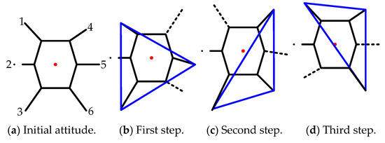
Figure 8.
Transfer order of legs in fault tolerant tripod gait in leg 2 fault state.
In the first process, legs 4 and 6 are lifted up to swing forward, legs 1, 3, and 5 are in the support state to push the body forward, and the robot posture is transformed from Figure 8a,b.
In the second step, legs 4 and 6 touch down, leg 1 is lifted up to step forward, leg 5 is raised to step forward at a slower velocity, legs 3, 4, and 6 provide support on the ground. Meanwhile, the body is moved passively, and the attitude changes from Figure 8b,c.
In the third process, leg 1 touches down, leg 5 continues to transfer forward while leg 3 is lifted to swing forward, legs 1, 4, and 6 support the body, which pushed the body to move forward, and the attitude changes from Figure 8c,d.
After the three processes, a whole walking cycle of the F-TT gait movement under the fault condition of leg 2 is completed, reverting to the initial attitude in Figure 8a and looping the cycle.
3.3. Measure to Improve the Stability of F-TT Gait
In Section 3.2, when a malfunctioning robot performs the F-TT gait, it has the two states of stability and instability. As the hexapod robot moves, the COG of the hexapod robot will move out of the stable region composed of the supporting legs, resulting in the hexapod robot toppling. Locomotion moment, as shown in Figure 6b,c and Figure 8c, due to the forward movement of the body, causes the COG to gradually move out of stability. Aiming at the instability state of the robot, a measure is proposed to solve the problem of the ineligible stability margin of the hexapod robot with one leg fault: coxa initialization angle adjustment. An initial value of coxa joint angle is preset to increase the support area. For the legs involved in the unstable support state, the support area can be increased by selecting the appropriate coxa initialization angle within the allowed space. Figure 9 and Figure 10 demonstrate the initial attitude with or without coxa initialization angle adjustment. The figure on the left shows the initial attitude without coxa initialization angle adjustment while the initial attitude with coxa initialization angle adjustment is shown on the right.
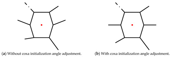
Figure 9.
Initial attitude of leg 1 fault.
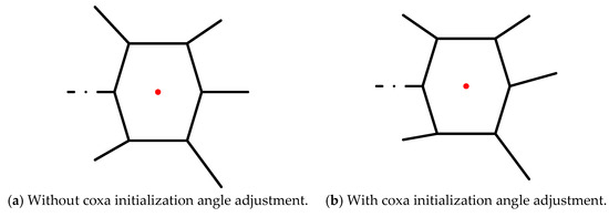
Figure 10.
Initial attitude of leg 2 fault.
The calculation of coxa initialization angle uses the Monte Carlo method to generate the random matrix of coxa initialization angle, restricting the adjustment range to [−20°, 30°]. Based on the planned gait parameters, the position of the foot ends of the next supporting phase is a known quantity. The stability margin is calculated using Equation (1). The solution with the stability margin greater than 0 is regarded as the feasible solution, and the evaluation index is defined as:
where is the coxa initialization angle of the leg i. The minimum value of the evaluation is regarded as the adjustment angle. Figure 11 shows the method to obtain the adjusted angle.
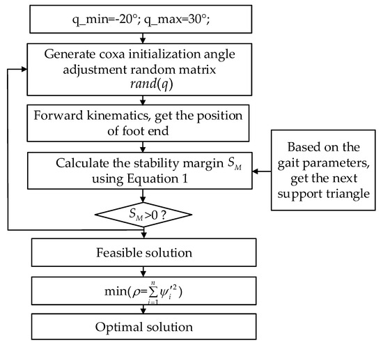
Figure 11.
The method to obtain the adjusted angle.
When a fault is detected, the robot resets to its original attitude and uses the coxa initialization angle adjustment method to calculate the angle of the initialization angle of the coxa joint. In a very short time, each leg is raised and swung to the initialization angle of the coxa joint to obtain a higher stability margin, and then begins to enter the fault-tolerant trip gait stage. By the measure of coxa initialization angle adjustment, the motion of Figure 6 and Figure 8 translates to that shown in Figure 12 and Figure 13, respectively. It can be seen that the stability margin is increased, and the COG is in the interior of the supporting triangle, which meets the static stability requirements.
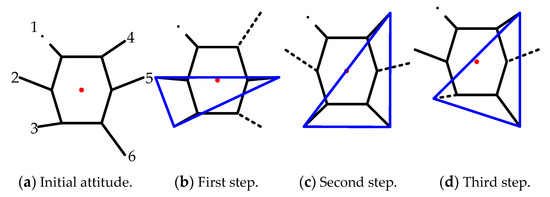
Figure 12.
F-TT gait locomotion with coxa initialization angle adjustment in leg 1 fault state.
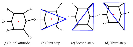
Figure 13.
F-TT gait locomotion with coxa initialization angle adjustment in leg 2 fault state.
4. Trajectory Planning of the F-TT Gait
The trajectory planning includes two parts: the motion trajectory of the COG, and the swing trajectory of the foot end. By controlling the joint of the legs supported on the ground, the control of the COG can be realized. The leg swinging in the air needs to meet certain constraints. The control of the attitude of the body is not involved, only the displacement and velocity in the X- and Y-axis is considered. In order to verify the feasibility of the F-TT gait, the linear uniform motion of the robot on an even road is planned.
For the transfer legs, to reduce the impact, two aspects should also be taken into consideration: one is that the velocity at the posterior extreme position (PEP) and anterior extreme position (AEP) is 0; the other is that there is no jump in the acceleration curve [27]. The motion of the transfer phase can be divided into two directions, namely, longitudinal and vertical motion. The longitudinal motion needs to meet the following conditions:
where is the current location of the legs in Y-axis.
The locomotion of the transfer leg in the vertical direction is lifted at the AEP, reaches the highest point at the middle position (MP) and is then put down at the PEP, so the vertical locomotion trajectory should satisfy the following conditions:
where is the stride height.
The velocity components of the foot end , and are assumed to be:
where and are constant. Through the initial conditions, the displacement of the foot end is obtained:
The COG moves forward at a uniform speed, so the velocity during walking is:
The displacement equation is as follows:
According to the foot trajectory planned in Equation (21) and Equation (23), the foot trajectory curve during a period is shown in Figure 14.
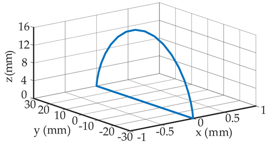
Figure 14.
Foot trajectory curve of the hexapod.
After obtaining the trajectory of the COG and the foot, the angular velocity of the leg joint can be solved.
From Equation (16), the F-TT gait we proposed applies a different duty factor to different legs. The duty factor of is 1/3, and that of the other legs is 2/3, which results in the period of the transfer phase of () being twice that of the other non-fault legs (). The relationship between , , and is:
Because of the identity of the leg motion cycle, the period of the support phase of () is half that of the other non-fault legs (). The relationship between , , and is:
5. Simulations and Experiments
The simulation analysis and walking experiments of the F-TT gait were carried out for the leg 1 fault and leg 2 fault states. Parameters of the physical prototype model used are shown in Table 3. The locomotion period is assumed to be 3 s. Each process is executed in 1 s.

Table 3.
Simulation parameters setting.
5.1. Simulation Results
The fault-tolerant tripod gait simulation of the hexapod robot was undertaken using the virtual prototype software ADAMS and MATLAB. The hexapod and ground were established in SolidWorks and imported to ADAMS. The constraints and driving and other parameters were established in ADAMS, and the control system was designed in Simulink.
5.1.1. Simulation Results with Leg 1 Fault
In a period, three processes are executed in sequence. Legs alternately transfer and support. Figure 15 and Figure 16 show some simulation sequences under the leg 1 fault state at different times from the lateral and the vertical view, respectively. The swing sequence of the legs can be observed in Figure 15, and accords with the planned sequence. Figure 16 displays the posture after each process in the F-TT gait; the gesture after coxa initialization angle adjustment has been demonstrated in Figure 16 when . To measure the locomotion of the hexapod robot, the displacement curves of the COG are shown in Figure 17. It can be concluded that the robot has a uniform speed along the Y-axis, and the fluctuation in the X and Z directions is slight. The main reason is that, due to the failure of leg 1, the symmetrical structure of the hexapod is damaged and the left side is only supported by one leg, resulting in about 10 mm displacement in the X-axis direction in three periods. In order to observe the stability margin intuitively, the support position is measured, and the stability margin is calculated using Equation (1). Figure 18 presents the detail at any time the stability margin is nonnegative.
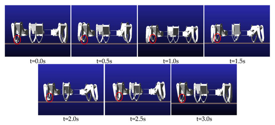
Figure 15.
Lateral view of one period simulation sequence with leg 1 fault.

Figure 16.
Vertical view of one period simulation sequence with leg 1 fault.
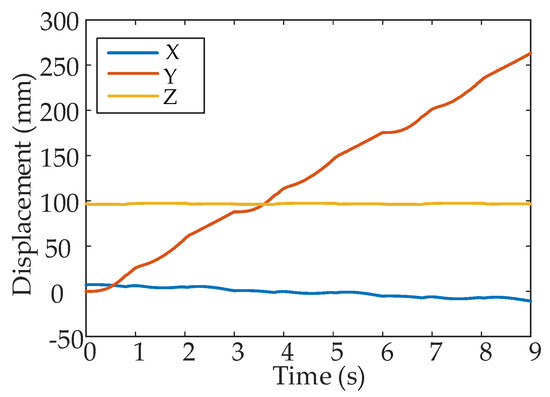
Figure 17.
The displacement of the hexapod body with leg 1 fault.
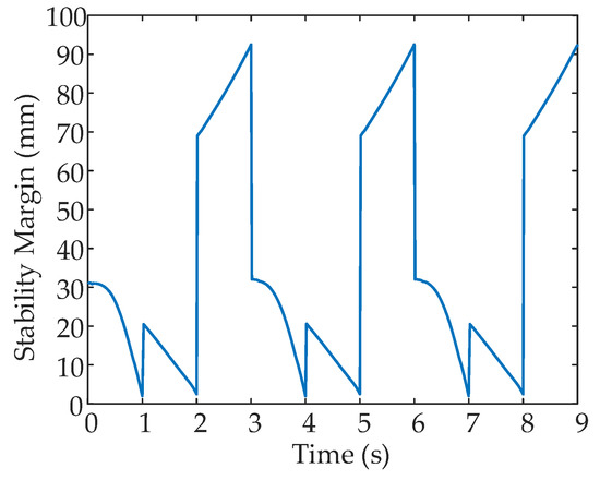
Figure 18.
Stability margin variation with leg 1 fault.
5.1.2. Simulation Results with Leg 2 Fault
The same items are measured when leg 2 is subject to a fault. According to the measure to improve the stability of the F-TT gait, the coxa initialization angle adjustment is made. Figure 19 shows a sequence of motion from the lateral view direction. The gesture and motion of each process are shown in Figure 20. It is obvious that the five non-faulty legs of the hexapod produce coordinated movement consistent with the planned sequence, and realize the smooth locomotion of the hexapod. The displacement of the COG is measured and shown in Figure 21. It can be seen that there is little or no deviation from the Y-axis, and the velocity along the Y-axis is steady. The stability margin value is shown in Figure 22. However, there are some critical values, since the transition between transfer phase and support phase occurs at specific moments.
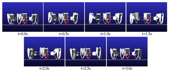
Figure 19.
Lateral view of one period simulation sequence with leg 2 fault.

Figure 20.
Vertical view of one period simulation sequence with leg 2 fault.
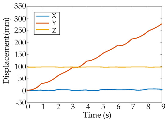
Figure 21.
The displacement of hexapod body with leg 2 fault.
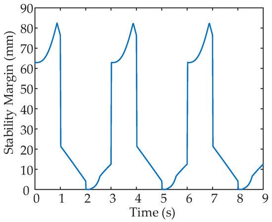
Figure 22.
Stability margin variation with leg 2 fault.
Combined with the above analysis, the F-TT gait of the hexapod allows one leg to fail, and the hexapod robot can walk smoothly due to the planned F-TT gait and the coxa initialization angle adjustment.
5.2. Experiment Results
To verify the effectiveness of the proposed fault-tolerant gait in practical robots, the experiments were implemented in an authentic hexapod robot. The experimental platform of the hexapod robot is illustrated in Figure 23. For the experiments, six force sensors were installed at the bottom of the foot end to collect the normal contact force between the foot and the ground, and a gyroscope, mounted on the body center, collected the attitude data of the hexapod body.
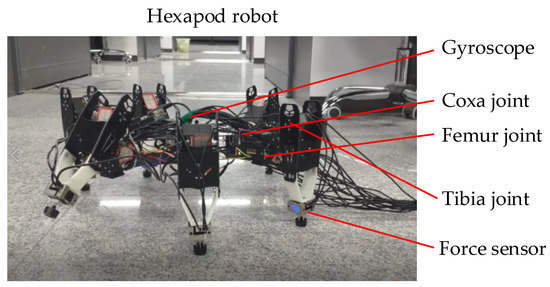
Figure 23.
The test platform of the hexapod robot.
5.2.1. Experiment Results with Leg 1 Fault
Figure 24 shows a set of snapshots of the walking experiment with leg 1 fault; clearly, the legs lift, transfer and support as planned. Figure 25 shows the curve of the normal contact force data collected at the foot end. The force can reflect the phase of each leg, because it exists only in the support phase. Leg 1 has no contact force with the ground, and the remaining five normal legs alternate to form a support triangle. At least three legs are in the support phase at each time. Figure 26 shows the attitude data of the COG. The pitch and roll angle change slightly, ranging from −1.0° to 1.0°, and the yaw angle ranged from −2.0° to 2.0°.
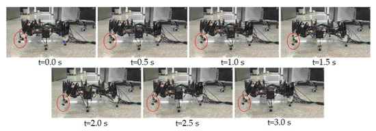
Figure 24.
A set of snapshots of the walking experiment with leg 1 fault.
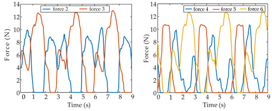
Figure 25.
Contact force in leg 1 failure experiment.
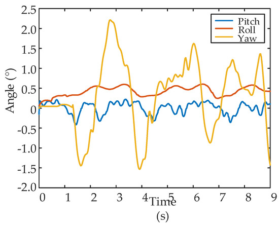
Figure 26.
The pitch, roll and yaw angle of the center of gravity (COG) in leg 1 failure experiment.
5.2.2. Experiment Results with Leg 2 Fault
The experiment of the F-TT gait with leg 2 fault was also carried out. Figure 27 shows a set of snapshots of the walking experiment in the leg 2 failure, which show the motion state of the robot at different times. Figure 28 shows the normal contact force data collected at the foot, with the data smoothed by Gauss filter. The force changes periodically. The weight of the body is not evenly distributed to each supporting foot end; for example, the contact force of leg 6 and the ground is relatively small, which may be because the model is rigid. However, there should be an elastic buffer device between the foot and the ground, such as a spring. Figure 29 shows the attitude data of the COG. The pitch and roll angle ranged from −1.0° to 1.0°, and the yaw angle ranged from −1.0° to 2.0°.
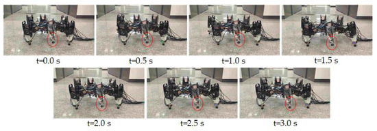
Figure 27.
A set of snapshots of the walking experiment with leg 2 fault.
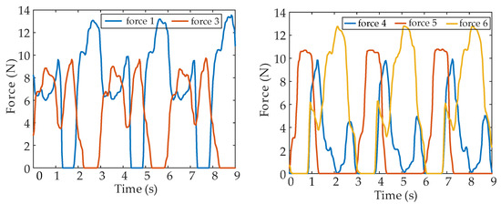
Figure 28.
Contact force in leg 2 failure experiment.
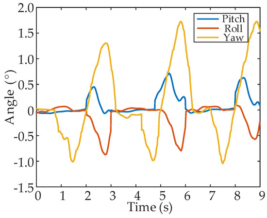
Figure 29.
The pitch, roll and yaw angle of the COG in leg 2 failure experiment.
The experiment results show that the locomotion of the hexapod robot is stable. It can be concluded through the experimental process that the movement of the robot is coordinated, and the hexapod robot can move smoothly and straight. The availability and rationality of the F-TT gait and the measures to improve stability are further proved.
6. Conclusions
In this paper, we focus on the fault-tolerant tripod gait of a hexapod robot with failure of one leg. A gait with different duty factors in different legs and a stability improvement method are proposed, which greatly improves the walking stability and the adaptability of the robot in complex environments. The specific research results are as follows.
Based on the prototype structure of the hexapod robot, the geometric relationship between the links on the legs of the robot is obtained. The D-H method is used to establish a kinematic model of the hexapod robot, which provides a theoretical basis for the subsequent F-TT gait research.
This research proposes a new gait generation mechanism of the tripod gait for a hexapod with a faulty leg, which results in a continuous gait. The advantage of the continuous tripod gait is that it has higher locomotion velocity, which helps to maintain the fast movement ability of the hexapod robot. An adjustment method based on pre-adjustment of the coxa joint is proposed to improve stability. This proposed method also provides an evaluation scheme to obtain the optimal adjustment. Through the coxa initialization angle adjustment method and the planned gait, the robot can move straight continuously without adding the adjustment phase during the movement.
The trajectories of the COG and swing legs are planned, and the joint angles of the straight walking gait are calculated with the combination of kinematic models and the planned trajectories. The simulations and experiments of the F-TT gait of the hexapod under the failure of leg 1 and leg 2 conditions are investigated separately. If the failure occurs in other legs, it can be resolved according to symmetry.
The F-TT gait effectively solves the forward motion problem of the hexapod under the condition of a single leg failure. However, this research was conducted only on even terrain. In the future, we will focus on the research of uneven terrain, and force control based on a dynamic model will also be considered. Furthermore, situations with locked legs that disturb the robot’s motion should be analyzed.
Author Contributions
Writing—original draft preparation, Y.L., X.F.; writing—review and editing, Y.L., X.F.; supervision, L.D., H.G., Y.L.; funding acquisition, Y.L., J.W.; grammar check and language polish, T.L. All authors have read and agreed to the published version of the manuscript.
Funding
This work was supported by National Natural Science Foundation of China (no. 51705097 and no. 91948202), Postdoctoral Science Foundation of China (no. 2017M621258), Self-Planned Task of State Key Laboratory of Robotics and System (HIT) (no. SKLRS201803C), the Fundamental Research Funds for the Central Universities (no. HIT.NSRIF.2020089), Scientific Research Foundation of Harbin Institute of Technology at Weihai (no. HIT(WH)201601), and Scientific Research Innovation Foundation of HIT(WH).
Conflicts of Interest
The authors declare no conflict of interest.
References
- Garcia, E.; Jimenez, M.; De Santos, P. The evolution of robotics research. IEEE Robot. Autom. Mag. 2007, 14, 90–103. [Google Scholar] [CrossRef]
- Holmes, P.; Full, R.; Koditschek, D. The dynamics of legged locomotion: Models, analyses, and challenges. Siam Rev. 2006, 48, 207–304. [Google Scholar] [CrossRef]
- Yang, K.; Rong, X.; Zhou, L.; Li, Y. Modeling and analysis on energy consumption of hydraulic quadruped robot for optimal trot motion control. Appl. Sci. 2019, 9, 1771. [Google Scholar] [CrossRef]
- Steingrube, S.; Timme, M.; Worgotter, F. Self-organized adaptation of a simple neural circuit enables complex robot behaviour. Nat. Phys. 2010, 6, 224–230. [Google Scholar] [CrossRef]
- Inagaki, K.; Kobayashi, H. Adaptive wave gait for hexapod synchronized walking. In Proceedings of the IEEE International Conference on Robotics & Automation, San Diego, CA, USA, 8–13 May 1994. [Google Scholar]
- Cruse, H.; Kindermann, T.; Schumm, M. Walknet—A biologically inspired network to control six-legged walking. Neural Netw. 1998, 11, 1435–1447. [Google Scholar] [CrossRef]
- Schilling, M.; Cruse, H.; Arena, P. Hexapod walking: An expansion to Walknet dealing with leg amputations and force oscillations. Biol. Cybern. 2007, 96, 323–340. [Google Scholar] [CrossRef]
- Goerner, M.; Hirzinger, G. Analysis and evaluation of the stability of a biologically inspired, leg loss tolerant gait for six- and eight-legged walking robots. In Proceedings of the IEEE International Conference on Robotics & Automation, Anchorage, AK, USA, 3–8 May 2010; pp. 4728–4735. [Google Scholar]
- Liu, M.; Li, M.; Pang, J. Fault-tolerant gait implementation of hexapod robot based on finite state automata. In Proceedings of the 2017 29th Chinese Control and Decision Conference (CCDC), Chongqing, China, 28–30 May 2017; pp. 6800–6805. [Google Scholar]
- Moesch, F.; Litza, M.; Auf, A. Organic fault-tolerant controller for the walking robot oscar. In Proceedings of the 20th International Conference on Architecture of Computing Systems 2007 (ARCS), Zurich, Switzerland, 15 March 2007; VDE VERLAG GmbH: Berlin, Germany. [Google Scholar]
- Yang, J.; Kim, J. Fault-tolerant locomotion of the hexapod robot. IEEE Trans. Syst. Man Cybern. Part B Cybern. 1998, 28, 109–116. [Google Scholar] [CrossRef]
- Yang, J.; Kim, J. A fault tolerant gait for a hexapod robot over uneven terrain. IEEE Trans. Cybern. 2000, 30, 172–180. [Google Scholar] [CrossRef]
- Yang, J. Fault-tolerant gait planning for a hexapod robot walking over rough terrain. J. Intell. Robot. Syst. 2009, 54, 613–627. [Google Scholar] [CrossRef]
- Wang, Z.; Ding, X.; Rovetta, A. Analysis of typical locomotion of a symmetric hexapod robot. Robotica 2010, 28, 893–907. [Google Scholar] [CrossRef]
- Peng, S.; Ding, X.; Yang, F. Motion planning and implementation for the self-recovery of an overturned multi-legged robot. Robotica 2017, 35, 1107–1120. [Google Scholar] [CrossRef]
- Pan, Y.; Gao, F.; Du, Hui. Fault tolerance criteria and walking capability analysis of a novel parallel-parallel hexapod break walking robot. Robotica 2016, 34, 619–633. [Google Scholar] [CrossRef]
- Chen, X.; Gao, F.; Qi, C. Gait planning for a quadruped robot with one faulty actuator. Chin. J. Mech. Eng. 2015, 28, 11–19. [Google Scholar] [CrossRef]
- Du, H.; Gao, F. Fault tolerance properties and motion planning of a six-legged robot with multiple faults. Robotica 2017, 35, 1397–1414. [Google Scholar] [CrossRef]
- Cully, A.; Clune, J.; Tarapore, D. Robots that can adapt like animals. Nature 2014, 521, 503. [Google Scholar] [CrossRef] [PubMed]
- Chatzilygeroudis, K.; Vassiliades, V.; Mouret, J. Reset-free trial-and-error learning for robot damage recovery. Robot. Auton. Syst. 2017, 100, 236–250. [Google Scholar] [CrossRef]
- Roy, S.; Pratihar, D. Dynamic modeling, stability and energy consumption analysis of a realistic six-legged walking robot. Robot. Comput. Integr. Manuf. 2013, 29, 400–416. [Google Scholar] [CrossRef]
- Mcghee, R.; Iswandhi, G. Adaptive locomotion of a multilegged robot over rough terrain. IEEE Trans. Syst. Man Cybern. 1979, 9, 176–182. [Google Scholar] [CrossRef]
- Messuri, D.; Klein, C. Automatic body regulation for maintaining stability of a legged vehicle during rough-terrain locomotion. IEEE J. Robot. Autom. 1985, 1, 132–141. [Google Scholar] [CrossRef]
- Estremera, J.; Cobano, J.; Santos, P. Continuous free-crab gaits for hexapod robots on a natural terrain with forbidden zones: An application to humanitarian demining. Robot. Auton. Syst. 2010, 58, 700–711. [Google Scholar] [CrossRef]
- Roy, S.; Singh, A.; Pratihar, D. Estimation of optimal feet forces and joint torques for on-line control of six-legged robot. Robot. Comput. Integr. Manuf. 2011, 27, 910–917. [Google Scholar] [CrossRef]
- Ren, D.; Shao, J.; Sun, G.; Shao, X. The complex dynamic locomotive control and experimental research of a quadruped-robot based on the robot trunk. Appl. Sci. 2019, 9, 3911. [Google Scholar] [CrossRef]
- Gao, H.; Liu, Y.; Ding, L. Low impact force and energy consumption motion planning for hexapod robot with passive compliant ankles. J. Intell. Robot. Syst. 2019, 94, 349–370. [Google Scholar] [CrossRef]
© 2020 by the authors. Licensee MDPI, Basel, Switzerland. This article is an open access article distributed under the terms and conditions of the Creative Commons Attribution (CC BY) license (http://creativecommons.org/licenses/by/4.0/).