Article

Visual Information Requirements for Remotely Supervised Autonomous Agricultural Machines

Department of Biosystems Engineering, University of Manitoba, Winnipeg, MB R3T 5V6, Canada
*
Author to whom correspondence should be addressed.
Appl. Sci. 2020, 10(8), 2794; https://doi.org/10.3390/app10082794
Submission received: 26 March 2020 / Revised: 13 April 2020 / Accepted: 14 April 2020 / Published: 17 April 2020
(This article belongs to the Special Issue Applied Agri-Technologies)

Abstract

:
A study to determine the visual requirements for a remote supervisor of an autonomous sprayer was conducted. Observation of a sprayer operator identified 9 distinct “look zones” that occupied his visual attention, with 39% of his time spent viewing the look zone ahead of the sprayer. While observation of the sprayer operator was being completed, additional GoPro cameras were used to record video of the sprayer in operation from 10 distinct perspectives (some look zones were visible from the operator’s seat, but other look zones were selected to display other regions of the sprayer that might be of interest to a sprayer operator). In a subsequent laboratory study, 29 experienced sprayer operators were recruited to view and comment on video clips selected from the video footage collected during the initial ride-along. Only the two views from the perspective of the operator’s seat were rated highly as providing important information even though participants were able to identify relevant information from all ten of the video clips. Generally, participants used the video clips to obtain information about the boom status, the location and movement of the sprayer within the field, the weather conditions (especially the wind), obstacles to be avoided, crop conditions, and field conditions. Sprayer operators with more than 15 years of experience provided more insightful descriptions of the video clips than their less experienced peers. Designers can influence which features the user will perceive by positioning the camera such that those specific features are prominent in the camera’s field of view. Overall, experienced sprayer operators preferred the concept of presenting visual information on an automation interface using live video rather than presenting that same information using some type of graphical display using icons or symbols.

1. Introduction

The era of autonomous agricultural machines (AAMs) seems to be just around the corner. Engineers and researchers are working diligently to design AAMs that will enable farmers to increase the productivity of their operations. When contemplating the incorporation of automation into an existing machine, [1] presented a model that can be used by design engineers to identify which functions should be automated. Their model is based on the four-stage model of human information processing and proposes that automation can be applied to four distinct types of functions: information acquisition, information analysis, decision and action selection, and action implementation. The engineer’s task is to assign the appropriate level of automation (ranging from manual to fully autonomous) for each of the four distinct types of functions. An AAM is likely to have a high level of automation for each of these independent types of functions. Despite the fact that an AAM is designed to automate information acquisition and analysis (using various sensors), to automate decision-making (through well-designed programming or machine learning approaches), and to automate action implementation (through various actuators linked to on-board sensors), it is imperative that design engineers do not forget to consider human interaction with the automation. Although it might be tempting to think of AAMs working in the field as independent of any human interaction, it is prudent to consider a larger system that is composed of the AAM working autonomously in the field and the human who will be monitoring its operation from a location that is remote from the field [2,3,4]. From this larger system perspective, the human supervisor, who is interested in both the status and progress of the AAM, will remotely supervise the AAM through some type of display, which can be aptly described as an “automation interface”.
It has been observed that humans face difficulty in maintaining a high level of awareness of system states when the system is under the control of either another human or of automation [5]. This decline in situation awareness is problematic for the human responsible for supervising the AAM; the authors of [6] advised that special attention must be given to the design of the automation interface to minimize such reduction in situation awareness. The ultimate productivity of such a human–machine system will depend on the type of information that is presented to the supervisor through an automation interface and the ability of the supervisor to efficiently and effectively glean the information from the interface. Therefore, great importance must be placed on the design of the automation interface so that the entire human automation system can be optimized.
Previous studies [7,8,9] have suggested that video footage is essential to supervisors when monitoring a machine remotely. The authors of [10] proposed a system architecture to enable control of an autonomous tractor that included a “coordinating process”, which was to be handled by a coordinator located remotely in a farm office. They proposed the phrase “tractor mimic display” for the computer interface that would be used by the coordinator to obtain tractor status information [10], also suggesting that the mimic display would incorporate a “real-time video link to steerable on-board cameras” to allow the coordinator to have “a better understanding of the tractor’s environment.” Several other research groups have described similar concepts, where a remote supervisor has some level of control over one or more AAMs [7,11,12]. The authors of [10] stated that the inclusion of video will enable the supervisor to better understand the tractor’s environment, while the authors of [13] reported that a large majority of participants identified the presence of live video as being important for understanding machine functions. Furthermore, participants were more secure in their interpretation of visual information if live video was present [13]. Thus, there is a growing body of evidence to suggest that real-time visual information in the form of live video is an essential element for an automation interface.
With these potential benefits, it is necessary to know which regions of the agricultural machine and its surrounding environment should be targeted by visual sensors. The authors of [14] recognized seven “look zones” (or areas the operator is expected to visually monitor during operation) for a seeding machine, labeled as: (i) forward, (ii) right side, (iii) planter, (vi) planter edge, (v) display X (located at the top right corner from the operator’s seated position), (vi) display Y (located close to the right arm rest), and (vii) other. When researching the workload associated with operating an agricultural sprayer, the authors of [15] identified four sectors: (i) field ahead, (ii) left boom, (iii) right boom, and (iv) the lightbar guidance aid. They noticed that the amount of time operators spent looking at these regions varied with (i) operator experience and (ii) the presence of navigation devices (i.e., lightbars, autosteer technology). Designers of autonomous systems have also suggested various regions of the agricultural machine that warrant observation. For example, an interface for driverless tractor seeding equipment showed the view ahead of the machine as well as the left and right sides of the seeding implement, respectively [16]. In the interface developed by [17] for monitoring multiple agricultural robots, an aerial (satellite) view of the robots in the field was included.
These examples reveal that the visual information that is used by the operator to make important decisions is gathered from three primary sources: (i) the displays located inside the machine’s cab (i.e., information gathered automatically by sensors and translated into visual information for the operator), (ii) external field cues, and (iii) the implement. However, these authors do not specify or explain the information that is being gleaned from looking at each of these regions or quantify the importance of the information to the operation of the machine. Considering the cost and technical challenges associated with wireless transmission of live video and the risk of overcrowding the interface with multiple video displays, it is essential to determine the visual information that is typically used by the machine operator and if the visual information could be replaced with a graphical display (consisting of icons or symbols) on the interface without impacting the perception of the information. Therefore, the primary objective of the study was to determine and evaluate the visual information that is gleaned from the machine and its surrounding environment that assists the operator with the control of an agricultural machine. A secondary objective was to assess whether visual information present in live video could be replaced with a graphical display consisting of icons or symbols to represent various machine parameters. Some examples of graphical displays in conventional agricultural machines can be found in [13,14]; two examples are shown in Figure 1 below. Recognizing that visual information requirements will be different for distinct agricultural machines, the self-propelled agricultural sprayer was selected for this study.

2. Materials and Methods

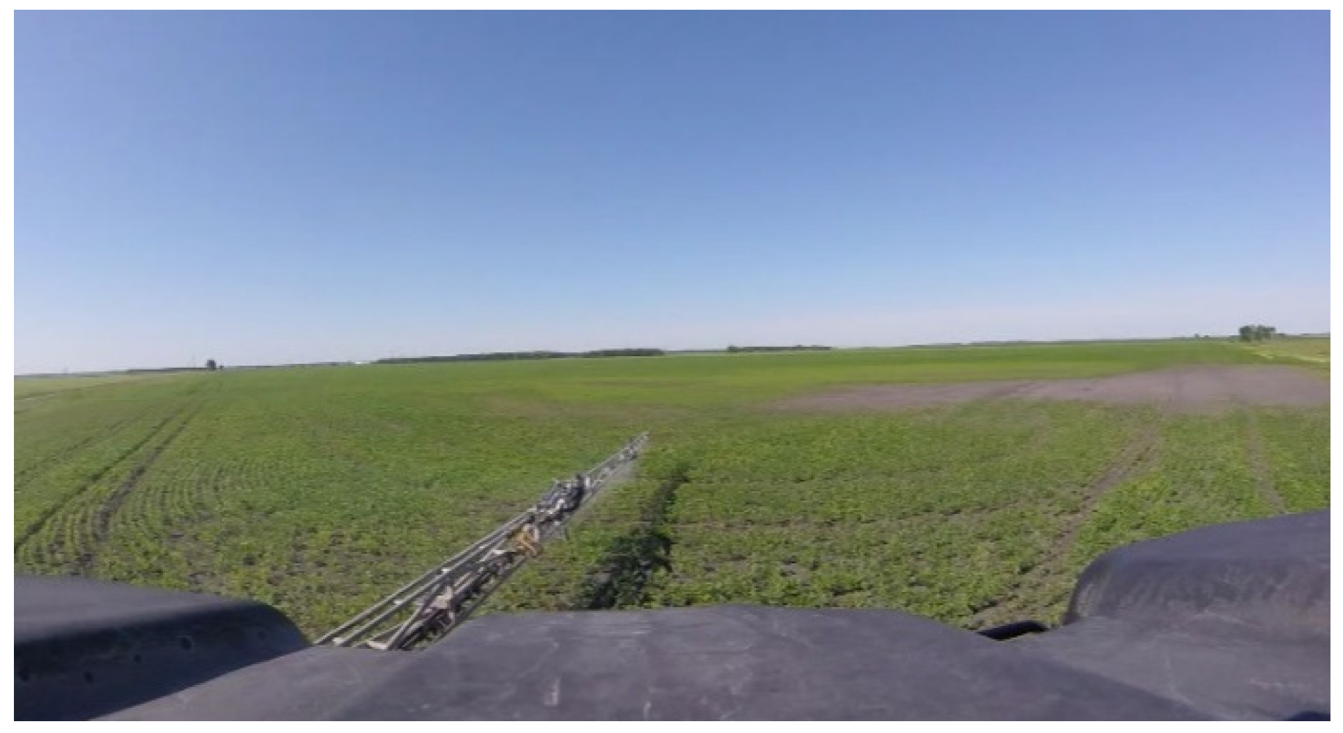
2.1. Identification of Look Zones during Manual Sprayer Operation

Arrangements were made to observe the operator of a high clearance, self-propelled agricultural sprayer (Rogator 1100 AGCO, Duluth, GA, USA) equipped with autosteer technology during the 2017 growing season. The participant who volunteered his sprayer and farmland for this phase of the study was a farm owner with 12 years of spraying experience who also performed custom spraying. One GoPro camera (GoPro, San Mateo, CA, USA), identified as camera M in Figure 2, was mounted on the windshield inside the sprayer’s cab to record the head and eye movement of the operator. The video was recorded on the morning of 6 July 2017 on a flat field in Rosser, MB (137 acres in size), for approximately 42 min of spraying time (this was the time taken to cover the entire field). During the spraying operation, the field boundaries were first sprayed in an anti-clockwise direction (to give room for the sprayer to turn easily without going outside the field), before straight parallel swaths were completed to traverse the remaining (unsprayed) area of the field. Subsequent analysis of the video footage from camera M was performed to identify the various look zones from the operator’s perspective as described by [14]. One of the co-authors rode along with the sprayer operator to ask questions (i) about the reasons for viewing the various look zones and (ii) the type of information being acquired when viewing the look zones. Although we asked questions during the actual spraying operation rather than interviewing the operator after data analysis had been completed as suggested by [14], this is an important complementary component of the experimental methodology.
To determine the amount of time the operator spent viewing each look zone, an algorithm for converting video recordings to images was developed using Python 2.7.16 (Python Software Corporation, Fredericksburg, VA, USA). The algorithm was used to convert the in-cab video recordings to images, each corresponding to 10 s of the recorded video footage. These images were then manually classified based on their look zones to measure the relative time the operator spent observing each zone.

2.2. Determination of Relevant Visual Information

Nine GoPro cameras (Hero Session, with horizontal field of view of 120° and a video resolution of 1920 × 1440) were mounted at different locations on a high clearance, self-propelled agricultural sprayer (Rogator 1100) to capture video footage of various regions of the sprayer and its environment while the sprayer was in operation (Figure 2). Various literature sources [14,15,17] were consulted to position the GoPro cameras on the sprayer. The rationale for the positioning of each camera is provided in Table 1. Some cameras were positioned to provide familiar views (i.e., look zones that a sprayer operator would typically see from the seated position), while other cameras were positioned to provide non-traditional views (i.e., look zones that are not visible from the seated position). Video recording was completed on the morning of 6 July 2017 on a flat field near Rosser, MB (137 acres in size). Video duration was approximately 42 min (which was the time required to spray the entire field). On a separate occasion (21 July 2017), video was recorded from a drone to provide an overhead view of the entire sprayer. A third party licensed drone operator assisted in capturing the overhead view on a field near Moosehorn, MB (120 acres in size); video was recorded for approximately 11 min and covered only a portion of the spraying operation.
Subsequent to collection of the video footage, clips of approximately 60 s in duration were selected from the full video, which showed a large variation in the spraying operation, the sprayer’s operational status, and the field or environmental conditions. Experienced sprayer operators (defined as having at least two years of experience operating a sprayer) were recruited from the prairie provinces (Manitoba, Saskatchewan, and Alberta) through industrial partners (Northstar Robotics), university, and farmers’ group contacts to participate in this phase of the research. Participants had the choice to either come in person to the Agricultural Ergonomics Lab at the University of Manitoba to complete the experiment or to complete the study online. All participants were required to give their consent prior to the commencement of the experiment. After answering demographic questions, participants were required to view a series of video clips and complete a questionnaire consisting of six questions. In total, eleven video clips were presented to each participant: one practice clip (clip P) and ten test clips (clips 1–10). The practice clip was included to allow participants to familiarize themselves with the experimental protocol and the questions that followed each video. Video clips showing familiar views of the sprayer and its environment (from the operator’s seated position) were presented before non-traditional views.
The video clip questionnaire comprised six questions. The first three questions were open-ended and required participants to describe: (i) what they saw in each video clip, (ii) the information gained from each video clip, and (iii) how they could use such information during operation of the sprayer. The fourth question asked if the video clip was something the operator typically viewed when operating a sprayer (yes/no response) and whether such a view is useful to the spraying operation (yes/no response). Question 5 required the participant to rank the importance of the visual information perceived using a 5-point Likert scale. In the final question, participants were asked to assess whether the information would be best presented via live video or whether the information could be encoded and incorporated into a graphical display for a sprayer. The video clip questionnaire was completed after viewing each video clip.

3. Results and Discussion

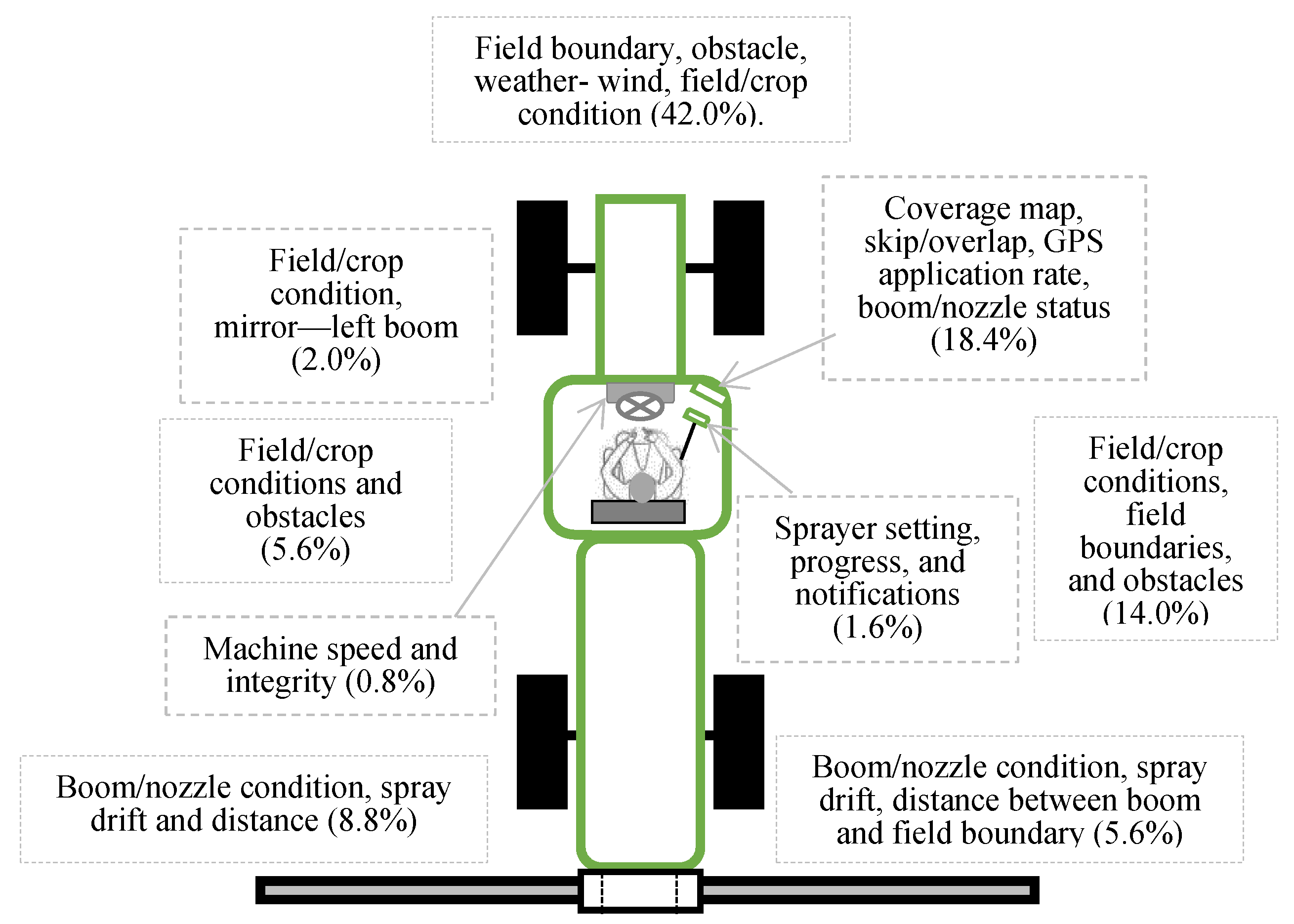
3.1. Identification of Look Zones during Manual Sprayer Operation

Analysis of the in-cab video footage (camera M) revealed nine look zones: (i) the view ahead of the operator from his seated position (i.e., front view); (ii) right side; (iii) right boom; (iv) left side; (v) left boom; (vi) upper display/mapping system (located at the top right corner from the operator’s seated position); (vii) a second display (located close to the right arm rest); (viii) sprayer’s dashboard/steering wheel; and (ix) left mirror/other (Figure 3). The participant was also seen making adjustments to the sprayer settings (through the displays) and checking his phone. Overall, he spent 39% of his time looking at the front view (Figure 3). This finding is consistent with the results of [15], who noted that sprayer operators spent the most time looking at the field ahead (i.e., front view), while the least attention was given to the dashboard information. When asked why he was looking at these regions, his reasons were (i) to determine how close the booms were to the field boundary, (ii) to assess if the nozzles were working properly, and (iii) to ensure that there were no obstacles close to the field boundaries and along the sprayer’s path that would require him to manually raise the boom. He also stated that the front view helped him to determine when to take over the steering wheel to initiate turning at the headland.
Another method for interpreting eye-tracking data is to represent the data as a function of time to give a sense of the cyclical nature of the task [14]. The data collected in this study are presented as a function of time in Figure 4. The data show that the operator was focused primarily on four look zones (front view, upper display, right side, and right boom) during the first 9 min of video footage—this corresponded to the time when he was spraying the field boundary. The front view enables the operator to assess where he is going and when to initiate turning, while the look zones to the right (i.e., right side and right boom) enable the operator to guide the sprayer along the field’s boundary. Therefore, when the operator was spraying along the field boundary, his attention was split between looking ahead and watching the right side of the sprayer. Once the field boundary was completed, the time spent viewing the right boom decreased noticeably.

3.2. Determination of Relevant Visual Information

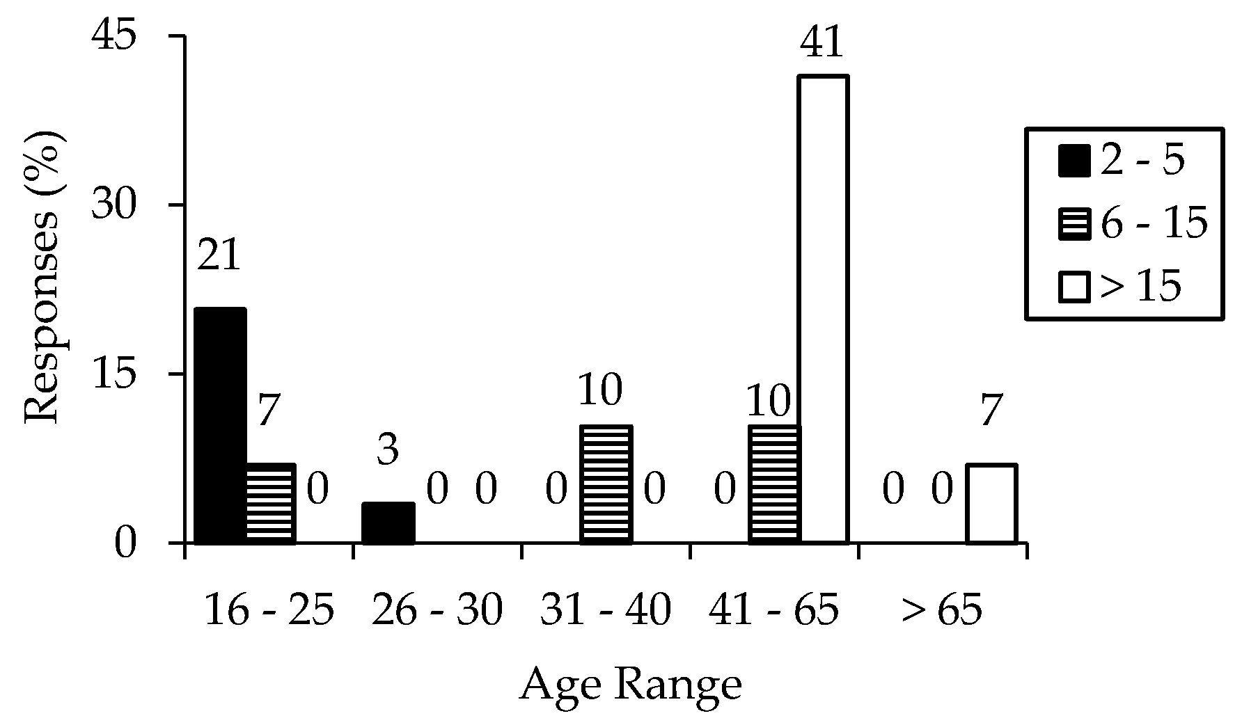
3.2.1. Participant Demographics

Twenty-nine experienced male sprayer operators participated in this phase of the research, 73% of which were from Manitoba, 17% from Saskatchewan, and 10% from Alberta. Among these 29 operators, 26 of them completed the study online, while the remaining operators completed the experiment in person. Approximately 50% of the respondents were within the age bracket of 41–65 and self-reported to have more than 6 years of experience operating a sprayer. Almost 30% of respondents were between the ages of 16 and 25, with two-thirds of these individuals having less than 2 years of experience operating a sprayer (Figure 5). Two of the participants reported that they had not operated a sprayer within the 12-month period prior to participating in this study. Only 10% of respondents were custom applicators, with the remaining respondents being farm owners (and therefore spraying only their own crops). Self-propelled sprayers were operated by 88% of respondents, with the remainder of the respondents using pull-type sprayers. All but one participant used auto-steer navigation technology when spraying.

3.2.2. Preliminary Observations from the Practice Clip

A screen shot from the practice video clip (clip P) is shown in Figure 6. Participants described the practice video clip as the left boom of a sprayer applying chemicals on the field (based on mist present in the video). Specific features that were seen included the spray pattern, properly functioning nozzles, stable but relatively low boom height, no visible obstacles in the field, and the presence of green crop (short in height). Participants also noticed that the field was level, had previously been sprayed (given the wheel tracks), and had several regions where no crop was growing. Most participants identified boom features (left boom height, nozzle, and spray pattern) and crop (or field) conditions as the information that was gained from watching the practice clip. A majority (86%) of the participants indicated that the information provided by the practice clip was something they typically viewed while spraying. Among the 14% of participants who did not indicate that such information was typically viewed during spraying, 50% of them felt that it would useful to see the areas provided by the practice clip. When asked how they would use the information gained from the practice clip, participants indicated that the information would help them to identify if nozzles were plugged, to set their guidance line to match the previous passes or tracks (since the field had previously been sprayed), to determine the type of spraying method that would be economical (i.e., adopting full application or spot spraying), and to make navigation decisions (e.g., deciding whether to go into low areas of the field, considering the risk of getting stuck). Two participants also noted that the information would give an operator the assurance that they were doing a good job. In response to the fifth question, 86% of the participants indicated that the information provided by the practice clip was “very important” or “extremely important”. Almost two-thirds of the participants (62%) indicated that it would be difficult to gain the same information if the live video was replaced with an encoded display. Overall, analysis of the data from the practice clip gave us confidence that participants accurately understood the purpose of the research and the questions in the questionnaire.

3.2.3. Information Gained from Test Clips

Screen shots from the ten clips used in this study are shown in Figure 7. Participant responses regarding the information gained from each video clip and how that information could be used (i.e., two of the open-ended questions from the questionnaire) are tabulated in the Appendix A. A summary of the responses to questions 4–6 is provided in Table 2, with full details provided in the Appendix A. Only two of the video clips (1 and 2) were typically viewed by a majority of the participants when operating their sprayers (Table 2). Not surprisingly, these were the only two video clips where a majority of participants identified the level of importance of the information provided to be “very important” or “extremely important”. Video clips 3 through 7 were not perceived to provide visual information that is relevant to the task of operating an agricultural sprayer.
The utility of the information provided in the video clips is more difficult to summarize. Generally, participants used the video clips to obtain information about the boom status, the location and movement of the sprayer within the field, the weather conditions (especially the wind), obstacles to be avoided, crop conditions, and field conditions. However, not all video clips were equally effective at providing information for these relevant parameters. Participants were able to gather information regarding the field conditions and travel speed of the sprayer from almost all of the clips. This outcome is not surprising given that the field was present in all the video clips and all clips featured some aspect of the sprayer against the stationary background of the field. It should be noted, however, that information about many of the other parameters was available in only a subset of the clips. Information about boom height, leaks, crop condition, wheel alignment with previous tracks, machine integrity, weather (wind), and obstacles could be determined from five to seven video clips. Information about the sprayer’s location, spray pattern, nozzle status (not plugged), spray drift, and how close the boom end was from the field boundary could be determined from only three or four video clips. Features such as sprayer clearance, section control, boom stability, turning at headland, size of the field, object behind the sprayer, field boundary, side of the sprayer, and knowing that the sprayer was in the right field could be determined from only one or two clips. Participants’ ability to identify any useful visual information from the sprayer and its surrounding environment was not dependent on how frequently such information was presented. As an example, 28% of participants considered “turning at headland” to be valuable, even though it was only presented in one of the clips (as perceived by participants), while fewer participants identified the “approximate travel speed” as visually important, even though it was perceived in all the video clips (see Appendix A).
Furthermore, environmental cues were considered important by participants when such cues were presented in relation to the spraying operation. For example, a higher number of participants perceived the field boundary to be valuable information when the end of the boom was visible with respect to the field boundary. However, fewer participants perceived the “field boundary” to be useful in clips that didn’t relate it to the spraying operation (boom), despite being visible. In other words, the field boundary is only important with respect to the position of the sprayer—the user does not care about the location of the field boundary unless it is presented in relation to the position of the boom. A summary of the information gained by operators based their look zones is presented in Figure 8.

3.2.4. Effect of Operators’ Experience on Information Gained

The years of operating experience of the participants did not influence their responses towards the level of importance of each video clip or with respect to replacing the clips with a graphical display; however, it did influence the responses to the open-ended questions in the questionnaire. Participants with intermediate or extensive experience operating a sprayer were able to articulate more useful or relevant information from the video clips than their peers with less operating experience (Table 3).

3.2.5. Influence of Camera Position

The experimental data were analyzed to determine the effect of the camera position on the visual information gained. When specific features of either the sprayer or its environment were prominently displayed within the frame of the camera, participants were more likely to comment on the information gained from that specific feature than information that could be gained from other less prominent features. For example, clip 2 focused mainly on the “right boom” and many participants identified features that were related to the boom as being valuable. Similarly, clip 9 emphasized the field and most participants focused on the relevant information that was gained from the field. This finding suggests that designers can influence which features the user will perceive by positioning the camera such that those specific features are prominent in the camera’s field of view.

3.2.6. Alternate Camera Placement

Other views that were suggested included a camera at the end of the boom facing forward (24%), a close-up view of the nozzle and its tip (24%), a view from under the sprayer facing backward to see the spray pattern behind the sprayer and wheels (10%), dashboards or displays (10%), and a camera that would focus on the wheel to show how well an operator was either following old tire tracks or steering within the rows of a corn crop (7%).

3.2.7. Live Video or Graphical Display of Information

A majority of participants indicated a preference for retaining important visual information in the format of live video on a hypothetical automation interface for remotely supervising an autonomous agricultural machine. For clips 1 and 2 (perceived to display the most important information), participants noted that it would be difficult to perceive the same information if they were replaced with graphical displays. However, they indicated that replacing clips 3, 5, 6, and 7 with a graphical display would not have any substantial impact on their ability to operate the sprayer. This divergent result may be due to the fact that most participants did not perceive any valuable information from the latter set of clips. Observed results from several of the other clips (i.e., clips 4, 8, 9, and 10) is more difficult to interpret. In-depth analysis revealed that the participant’s response to this question was related to the information perceived from the clip. For example, in clip 8, some participants identified relevant information such as spray drift, spray pattern, and backing up; these aspects of sprayer operation might be difficult to portray on a graphical display, perhaps leading these participants to prefer live video. For the same video clip, other participants reported no substantial impact when replacing live video with a graphical display. These participants identified features such as wheel alignment or following a previous wheel track—features that could perhaps be displayed more easily using a graphical display. Overall, experienced sprayer operators reported higher preference for presenting visual information on an automation interface using live video than presenting that same information using some type of graphical display.

4. Conclusions

Having video footage of the sprayer and its environment during spraying operation is important to the remote supervisor of an autonomous sprayer. Typically, experienced sprayer operators preferred: (i) the view ahead of the sprayer (from the operator’s seated position), (ii) a view of the boom and nozzles, and (iii) an aerial view of the sprayer in operation. The information that was perceived from these views included the right boom, nozzle status (plugged or not), spray pattern, obstacles in front or beside, poor areas in the field, wet spots, approximate travel speed, headlands, type of crop being sprayed, weather (windy and sunny), application rate, boom height, location of the sprayer, overall picture of the field (i.e., aerial view), and if the sprayer was moving and following the right path (moving straight). With this information, operators felt that they would be able to identify consistency in product application, changing elevation, and the upcoming field (e.g., headland). Experienced operators believed that this information could be used to determine if they needed to stop and clean a plugged nozzle, raise or lower a boom, continue spraying or stop spraying (in windy conditions), increase or reduce speed and droplet size, decide where to spray or where not to (if no automatic section control), when to adjust the wheel to stay on track or make turns, avoid spraying a neighbor’s field, avoid obstacles, avoid wet spots, and as tools for teaching and training a novice operator. The level of importance of the video clip increased with familiarity and how directly related the information is to the operation of a sprayer. Overall, visual information of highly important or preferred parts of the sprayer and its environment (as determined by experienced operators) should be retained in the format of live video rather than encoding the information as part of a graphical display.

Author Contributions

Conceptualization, U.E. and D.M.; methodology, U.E. and D.M.; formal analysis, U.E.; investigation, U.E.; writing—original draft preparation, U.E.; writing—review and editing, D.M.; visualization, U.E.; supervision, D.M.; project administration, D.M.; funding acquisition, D.M. All authors have read and agreed to the published version of the manuscript.

Funding

This research was funded by the Natural Sciences and Engineering Research Council of Canada, grant number RGPIN-2018-05350.

Acknowledgments

The authors would like to acknowledge technical assistance from three summer students (E. Hawley, G. Dyck, and F. Ogidi).

Conflicts of Interest

The authors declare no conflict of interest.

Appendix A

Table A1. A summary of participants’ responses to each video clip.
Video Clip Clip DescriptionInformation Gained (Multiple Responses Allowed; %)How Information Gained Can Be Used (Multiple Responses Allowed)Typically Viewed; %Usefulness to “No” Participants; %LoI Ranking; %Replacing Clip with Display
1Front view from sprayer cabin (operator’s sitting position).Too windy to be spraying—48
Staying on track—28
Turning at headland—28
Field condition—17
Approximate travel speed—10
Obstacle—10
Crop condition—3
No comment—10
- Increase droplet size.
- Lower the boom.
- Avoid obstacle.
- Control speed at headland.
- Prevent overlap/miss.
- Utilize old track.
Yes: 97
No: 3
Yes: 0
No: 100
n = 1
L1 = 7
L2 = 0
L3 = 14
L4 = 24
L5 = 55
a = 55
b = 21
c = 24
2Right boom spraying chemical.No plugged nozzle—38
Boom height—28
Section control—21
How close is the boom end to the field boundary—21
Spray pattern—17
Crop condition—10
Obstacle—10
Approximate travel speed—10
Boom stability—3
Sharp turning—3
No comment—3
- Clean plug nozzles.
- Set/control boom height.
- Turn off boom.
- Avoid obstacle.
- Avoid spraying another field.
Yes: 93
No: 7
Yes: 100
No: 0
n = 2
L1 = 3
L2 = 3
L3 = 10
L4 = 28
L5 = 55
a = 62
b = 17
c = 21
3 Left side of sprayer.No information gained—48
Machine integrity—10
Travel speed—10
Sprayer clearance—7
No leaks—7
Boom height—7
Sprayer response to field topography—7
Boom is still attached—3
Crop condition—3
Boom stability—3
Field condition—3
No comment—7
- Not useful
- Stop if a leak was identified.
- Changing travel speed.
Yes: 10
No: 90
Yes: 23
No: 65
Blank: 12
n = 26
L1 = 54
L2 = 14
L3 = 14
L4 = 14
L5 = 4
a = 21
b = 10
c = 69
4Underside of sprayer.No leaks—31
No information gained—24
Sprayer clearance—17
Machine integrity—17
Travel speed—10
Crop condition—10
Wheel alignment with previous path/track—10
Crop respond to tire—7
Field condition—3
Sprayer is still moving—3
- Keep straight
- Stop if there was a leak.
- Keep your wheels in the existing sprayer tracks
- Not useful
- Adjust travel speed.
- How high to set your center boom
Yes: 3
No: 97
Yes: 32
No: 64
Blank: 4
n = 28
L1 = 31
L2 = 34
L3 = 21
L4 = 7
L5 = 7
a = 41
b = 10
c = 48
5Distance sprayer working in a windy field.No information gained—34
Windy—31
Sprayer is in the right field—10
Path taken by sprayer—10
Sprayer is still moving—7
Spray drift—3
How close is the boom end from the field boundary—3
Boom height—3
Field condition—3
Size of the field—3
- Not useful
- Possibly stop spraying
- Confirm that proper crop is being sprayed and that machine is in the correct field.
Yes: 7
No: 93
Yes: 22
No: 74
Blank: 4
n = 27
L1 = 48
L2 = 31
L3 = 10
L4 = 3
L5 = 7
a = 28
b = 21
c = 48
6View of spray/rinse tank and field.No information—59
Leaks on rinse tank—17
Weather—7
Driving straight—7
Sprayer is still moving—3
Obstacles—3
Travel speed—3
Obstacle—3
Travel speed—3
Field condition—3
Machine integrity—3
Tank latch is secure—3
- Assist when passing low hanging wire or shed.
- Mange leaks/open lid.
Yes: 0
No: 100
Yes: 17
No: 79
Blank: 3
n = 29
L1 = 59
L2 = 21
L3 = 10
L4 = 10
L5 = 0
a = 28
b = 7
c = 66
7Left side of sprayer showing crop.No information—66
Obstacles—10
Sprayer is still moving—7
Field condition—7
Crop condition—3
Awareness of another vehicle when driving off field—3
Weather—3
Side of sprayer—3
Travel speed—3
Identify the field—3
Sprayer location—3
- Assist when turning unto a roadway.
- Plan for low spot/ditches.
- Avoid obstacles.
Yes: 28
No: 72
Yes: 14
No: 81
Blank: 5
n = 21
L1 = 62
L2 = 24
L3 = 10
L4 = 3
L5 = 0
a = 34
b = 0
c = 59
8Back of sprayer driving up a field.No information—31
Nozzle status—28
Boom height—17
Centre boom/nozzle—10
Spray pattern—10
Weather (wind)—7
Spray drift—7
Boom is fully open—7
Machine integrity—3
Obstacles—3
Leaks—3
Field condition—3
Travel speed—3
- Proper boom height adjustment.
- Adjust travel speed.
- Reduced time spent to check for plugged nozzle in the center section.
Yes: 10
No: 90
Yes: 50
No: 46
Blank: 4
n = 26
L1 = 34
L2 = 10
L3 = 14
L4 = 38
L5 = 3
a = 24
b = 31
c = 41
9Aerial (drone) view of sprayer operating in a canola field.How close is the boom end from the field boundary—31
Sprayer’s location—28
Field condition—28
Obstacle—14
Crop condition—14
Spray pattern—7
Path followed—7
Boom is fully open—7
No information gained—7
Machine integrity—3
Travel speed—3
Section control—3
Field boundary—3
Spray drift—3
Boom height—3
- Plan routes to avoid hidden obstacles
- Adjust to stay within field boundary
- Know how much work had been done
Yes: 3
No: 97
Yes: 82
No: 14
Blank: 4
n = 28
L1 = 7
L2 = 21
L3 = 41
L4 = 24
L5 = 7
a = 52
b = 14
c = 31
10Field behind the sprayer while it is moving.No information gained—31
Spray drift—31
Wheel alignment with old track/path—28
Travel speed—10
Front and rear wheel aligned properly—7
Leaks-7
Weather (wind)—7
Nozzle status based on tramlines—3
Spray pattern—3
Sprayer’s location—3
Object behind sprayer—3
Crop condition—3
Field condition—3
- When backing out.
- Align wheel properly.
- Select/change droplet size or spray pressure.
- Decide whether to continue spraying or not.
Yes: 14
No: 86
Yes: 48
No: 48
Blank: 4
n = 25
L1 = 21
L2 = 28
L3 = 21
L4 = 14
L5 = 17
a = 41
b = 3
c = 52
n = 29, unless otherwise stated. Blank means no response was made. LoI: level of importance. L1 = not at all important; L2 = of little importance; L3 = of average importance; L4 = very important; L5 = extremely important. a = believe it would be more difficult to gain the information required to operate the sprayer if the live video was replaced with a graphical display; b = I believe it would be easier to gain the information required to operate the sprayer if the live video was replaced with a graphical display; c = I do not believe there would be any substantial impact on my ability to operate the sprayer if the live video was replaced with a graphical display.

References

  1. Parasuraman, R.; Sheridan, T.B.; Wickens, C.D. A model for types and levels of human interaction with automation. IEEE Trans. Syst. Man Cybern. Part A Syst. Hum. 2000, 30, 286–297. [Google Scholar] [CrossRef] [PubMed] [Green Version]
  2. Alexander, R.; Herbert, N.; Kelly, T. The role of the human in an autonomous system. In Proceedings of the 4th IET System Safety Conference, London, UK, 26–28 October 2009. [Google Scholar] [CrossRef] [Green Version]
  3. Schreckenghost, D.; Fong, T.; Milam, T. Human supervision of robotic site surveys. In American Institute of Physics Conference Proceedings; American Institute of Physics: College Park, MD, USA, 2008; Volume 969, pp. 776–783. [Google Scholar] [CrossRef] [Green Version]
  4. Bechar, A.; Vigneault, C. Agricultural robots for field operations: Concepts and components. Biosyst. Eng. 2016, 149, 94–111. [Google Scholar] [CrossRef]
  5. Endsley, M. From here to autonomy: Lessons learned from human-automation research. Hum. Factors 2017, 59, 5–27. [Google Scholar] [CrossRef]
  6. Endsley, M.; Kiris, E.O. The out-of-the-loop performance problem and level of control in automation. Hum. Factors 1995, 37, 381–394. [Google Scholar] [CrossRef]
  7. Stentz, A.; Dima, C.; Wellington, C.; Herman, H.; Stager, D. A system for semi-autonomous tractor operations. Auton. Robot. 2002, 13, 87–104. [Google Scholar] [CrossRef]
  8. Berenstein, R.; Edan, Y.; Halevi, I.B. A remote interface for a human-robot cooperative vineyard sprayer. In Proceedings of the 11th International Conference on Precision Agriculture, Indianapolis, IN, USA, 15–8 July 2012. [Google Scholar]
  9. Edet, U.; Hawley, E.; Mann, D.D. Remote supervision of autonomous agricultural sprayers: The farmer’s perspective. Can. Biosyst. Eng. Génie Biosyst. Can. 60 2018, 2.19–2.31. [Google Scholar] [CrossRef]
  10. Blackmore, S.; Fountas, S.; Have, H. Proposed system architecture to enable behavioral control of an autonomous tractor. In Proceedings of the Automation Technology for Off-Road Equipment Proceedings of the 2002 Conference, Chicago, IL, USA, 26–27 July 2002; pp. 13–23. [Google Scholar] [CrossRef]
  11. Johnson, D.A.; Naffin, D.J.; Puhalla, J.S.; Sanchez, J.; Wellington, C.K. Development and implementation of a team of robotic tractors for autonomous peat moss harvesting. J. Field Robot. 2009, 26, 549–571. [Google Scholar] [CrossRef] [Green Version]
  12. Moorehead, S.; Ackerman, C.; Smith, D.; Hoffman, J.; Wellington, C. Supervisory control of multiple tractors in an orchard environment. In Proceedings of the 4th IFAC International Workshop on Bio-Robotics, Information Technology and Intelligent Control for Bioproduction Systems, Urbana, IL, USA, 10–11 September 2009. [Google Scholar]
  13. Panfilov, I.; Mann, D.D. The Importance of Real-Time Visual Information for the Remote Supervision of an Autonomous Agricultural Machine. Can. Biosyst. Eng. 2018, 60. [Google Scholar] [CrossRef] [Green Version]
  14. Sanchez, J.; Duncan, J.R. Operator-automation interaction in agricultural vehicles. Ergon. Des. 2009, 17, 14–19. [Google Scholar] [CrossRef]
  15. Dey, A.K.; Mann, D.D. A complete task analysis to measure the workload associated with operating an agricultural sprayer equipped with a navigation device. Appl. Ergon. 2010, 41, 146–149. [Google Scholar] [CrossRef] [PubMed]
  16. CNH Industrial: The CNH Industrial Autonomous Tractor Concept (Full Version). Available online: https://www.youtube.com/watch?v=T7Os5Okf3OQ (accessed on 20 May 2018).
  17. Ishibashi, M.; Iida, M.; Suguri, M.; Masuda, R. Remote monitoring of agricultural robot using web application. In Proceedings of the IFAC Conference on Modelling and Control in Agriculture, Horticulture and Post Harvest Industry, Espoo, Finland, 27–30 August 2013; Volume 46, pp. 138–142. [Google Scholar] [CrossRef]
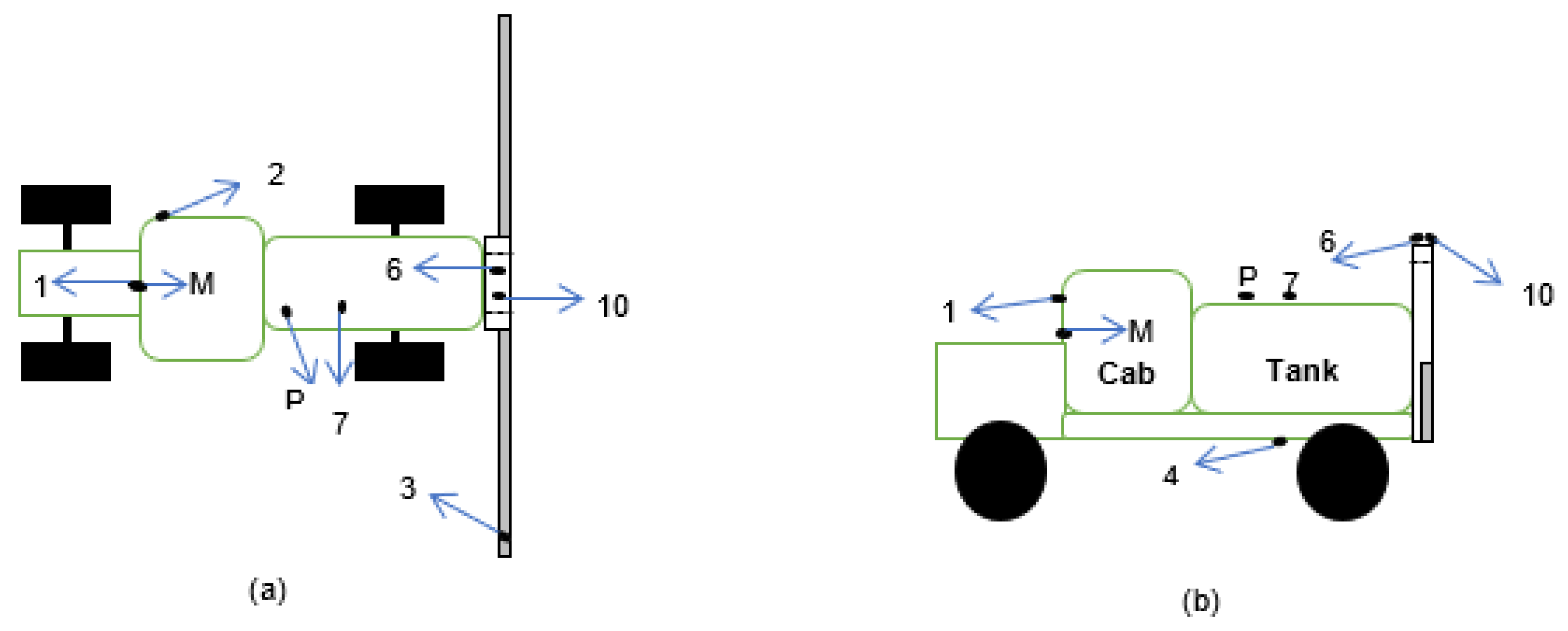
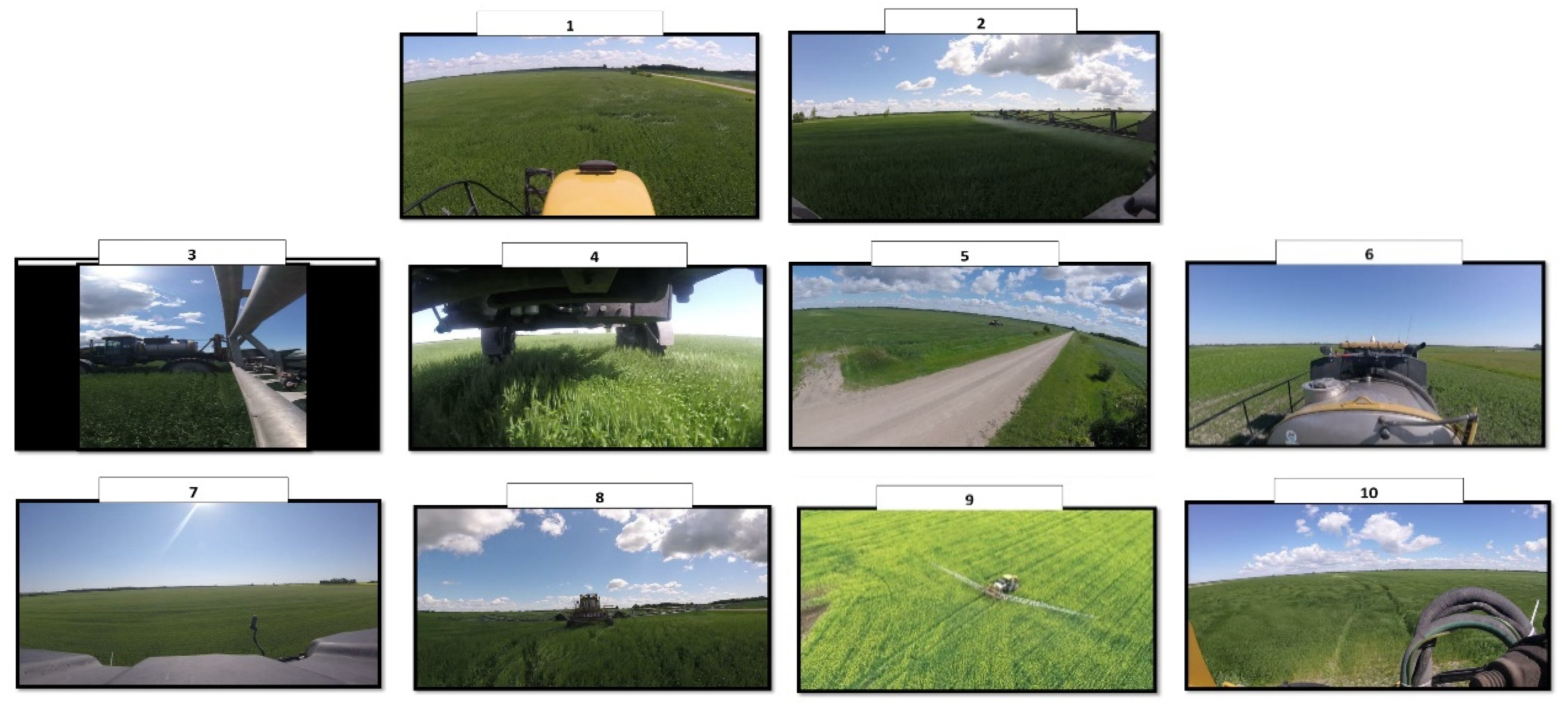
Figure 1. An example of a graphical display for a sprayer (adapted from [13]).
Applsci 10 02794 g001
Figure 2. A schematic drawing showing the various camera positions on the sprayer during the first phase of the project: (a) plan view; (b) side view. Cameras were placed on each dot, while arrows indicate the direction of the camera. Note: camera P = clip P; camera 1 = clip 1; camera 2 = clip 2. Camera 5 was mounted on a drone, while cameras 8 and 9 were third party hand-held cameras that were focused on the back of the sprayer and the field, respectively. Camera M was placed inside the sprayer’s cab to record the head and eye movement of the operator.
Applsci 10 02794 g002
Figure 3. Look zones from the operator’s perspective during spraying operation.
Applsci 10 02794 g003
Figure 4. Video data represented as a function of time to demonstrate the monitoring behavior of the operator during spraying operation. Each dot represents 10 s of the recorded video. Additionally, the gap at the beginning of the graph indicates the time interval between when the GoPro camera was turned on and when the spraying operation began.
Applsci 10 02794 g004
Figure 5. Grouping of participants by age and with respect to their years of experience in spraying.
Applsci 10 02794 g005
Figure 6. A screen shot of the practice video clip (clip P).
Applsci 10 02794 g006
Figure 7. Screen shots from clips 1–10.
Applsci 10 02794 g007
Figure 8. Information gained based on from the operator’s look zone during spraying operation.
Applsci 10 02794 g008
Table 1. Rationale for choosing each camera position.
CameraRationale
MAbility to observe the operator’s head and eye movement (from his seated position) during the spraying operation.
1To capture the field ahead of the sprayer and other environmental cues.
P and 2To capture the view of the right and left boom, respectively, as perceived from the typical seated position of an operator in the cab of a self-propelled sprayer.
3, 4, 6, 7, 8, and 10To capture regions around the sprayer that are currently not visible to operators (from their seated position).
5 and 9To capture off-field (third party) views and assess their usefulness to the remote supervisor of the autonomous sprayer(s).
Table 2. Summary of responses from experienced sprayer operators (n = 29) who completed the video clip questionnaire.
Video ClipTypically Viewed (%)High Level of Importance * (%)Participant Preference for Visual Information
Live Video (%)Graphical Display (%)No Substantial Impact (%)
19779552124
29383621721
31018211069
4314411048
5710282148
601028766
728334059
81041243141
9331521431
10143141352
* Proportion of participants who rated the level of importance as either “very important” or “extremely important” to the operation of the sprayer.
Table 3. Information gained as a function of a participant’s experience.
ClipGeneral Description< 5 Years Experience5–15 Years Experience>15 Years Experience
1Front view from sprayer cabin.Turning, speed, track pathTurning, track path, windy.Turning, windy, obstacle.
2Right boom spraying chemical.Nozzle status, boom height.Nozzle status, boom height, distance from field boundary, spray pattern.Sprayer is operating, crop condition, boom height, obstacles, travel speed, distance from field edge.
3Left side of sprayer.Leak, how deep you can sink, very little.Topography, leaks, teaching moment, machine integrity, not much.Boom is still attached, travel speed, boom stability, not much.
4Underneath of sprayer.Leaks, crop respond, crop height.Field condition, leaks, machine integrity, not much.Crop conditions, leaks, crop height, crop damage, travel speed, clearance, nothing much.
5Distance sprayer working in a windy field.Field variability, size of field, boom height, not much.Wind condition, amount of drift, sprayer location, not much.Weather, sprayer is in the desired field, windy, sprayer is still moving, not much.
6View of spray/rinse tank and field.Tank is full, sprayer is driving straight, nothing much.Machine integrity, weather, nothing.Leaks, field conditions, sprayer is operating, making turns, obstacles, nothing.
7Left side of sprayer showing crop.Side view of sprayer, nothing.Beneficial for off-field operation, nothing.Travel speed, crop condition, weather, field conditions, obstacles, nothing.
8Back of sprayer driving up a field.Nozzle status, nothing.Nozzle status, spray pattern, boom height, spray drift, leaks, nothing.Sprayer is operating, field and weather conditions, nozzle status, wind, travel speed, spray drift.
9Aerial (drone) view of sprayer operating in a canola field.Field conditions, sprayer’s location, sprayer is applying chemical within boundary.Distance of boom from field boundary, field condition, sprayer’s location, obstacles.Sprayer is operating, following field edge, obstacles, field conditions, location of sprayer, boom is fully open, travel speed.
10Field behind the sprayer while it is moving.Spray drift, crop damage due to tire.Spray drift, travel speed, field condition, crop condition, staying on track, wheel alignment, not much.Spray drift, weather, spray pattern, travel speed, track alignment with previous path, front and rear wheel alignment.

