Article

Performance of a Solar Absorption Cooling System Using Nanofluids and a Membrane-Based Microchannel Desorber

by
María Venegas
1,*,
Néstor García-Hernando
2,
Alejandro Zacarías
3 and
Mercedes de Vega
2
1
ISE and GTADS Research Groups, Department of Thermal & Fluids Engineering, UC3M, 28911 Madrid, Spain
2
ISE Research Group, Department of Thermal & Fluids Engineering, UC3M, 28911 Madrid, Spain
3
Instituto Politécnico Nacional, ESIME Azcapotzalco, Ciudad de México C.P. 02250, Mexico
*
Author to whom correspondence should be addressed.
Appl. Sci. 2020, 10(8), 2761; https://doi.org/10.3390/app10082761
Submission received: 24 March 2020 / Revised: 12 April 2020 / Accepted: 14 April 2020 / Published: 16 April 2020
(This article belongs to the Special Issue Solar Cooling Systems)

Abstract

:

Featured Application

Absorption cooling systems fed by solar thermal energy.

Abstract

In this work, the performance of a single effect absorption cooling system fed by solar thermal energy is evaluated. The absorption chiller includes a membrane-based microchannel desorber using three types of nanoparticles: Al2O3, CuO, or carbon nanotubes (CNT). Correlations available in the open literature to calculate the thermal conductivity of nanofluids are reviewed. Using experimental data for the water-lithium bromide solution (H2O-LiBr) with Al2O3 and CNT nanoparticles, the most appropriate correlation for thermal conductivity is selected. Nanofluid properties are evaluated using a concentration of nanoparticles of up to 5% in volume. The largest increase in the desorption rate (7.9%), with respect to using pure H2O-LiBr solution, is obtained using CNT nanoparticles and the maximum concentration of nanoparticles simulated. The performance of the chiller is evaluated and the daily solar coefficient of performance (SCOP) for the solar cooling facility is obtained. The best improvement with respect to the conventional system (without nanoparticles) represents an increase in the cooling effect of up to 6%. The maximum number of desorber modules recommended, always lower than 50, has been identified.

1. Introduction

Absorption cooling chillers can be fed by any heat source, including renewable or waste heat, for example, from solar thermal collectors. Any solar thermal facility, used to obtain domestic hot water and/or heating, can be used to provide air-conditioning in the summer season, obtaining the best use for the solar facility. In this way, the electricity consumed during summer can be reduced, decreasing possible peaks in the electrical grid.
In a single effect absorption chiller, there are four key components: absorber, desorber, evaporator, and condenser, as shown in Figure 1. In the desorber, an amount qd of heat is supplied to the solution flowing inside the device to separate a portion of the more volatile component (the refrigerant). In the case of the H2O-LiBr pair, the solution concentrated as a fraction of water in the superheated vapour state is separated. This vapour flows to the following component, the condenser, where the amount qc of heat is released to a recooling fluid (typically water coming from a cooling tower or ambient air). The superheated vapor is then cooled and condensed, ideally obtaining water in a saturated liquid state. These two components, desorber and condenser, work at the highest pressure inside the absorption chiller. For this reason, expansion devices are located at their outlets to reduce the pressure down to the values in the following devices (absorber and evaporator). In the condenser, liquid water expands in the throttling device to obtain a saturated two-phase flow that enters the evaporator. There, the remaining liquid water evaporates, thanks to the heat qe extracted from the external cold fluid, producing the desired cooling effect. Vapour generated enters into the absorber, where it comes into contact with the concentrated solution flowing from the desorber. Here, the solution absorbs the vapour and the absorption and dilution heats produced qa are transferred to an external recooling fluid. The diluted solution is then pumped again to the desorber to close the cycle. An additional component, a recovery heat exchanger, is added in real absorption chillers to improve the cycle efficiency. It is located between the desorber and the absorber and allows heat transfer from the hot concentrated mixture to the cold diluted one.
Figure 1 shows the typical configuration used for desorber and absorber in conventional absorption chillers, corresponding to shell and tubes exchangers. In the case of the desorber, the heating fluid circulates through the tubes, while solution boils inside the shell. In the absorber, the concentrated solution is dispersed in drops at the top of the tube bank, entering into contact with the vapour flowing from the evaporator. The heat released during absorption is extracted by the recooling fluid circulating through the tubes. Both components are very large, heavy, and very sensitive to vibrations. For this reason, absorption systems are not competitive with mechanical compression chillers, and many studies are being performed to improve their design.
In the last years, the use of microporous membranes located at the boundary between solution and vapour in desorbers of absorption chillers has been evaluated. In the case of components using microporous flat membranes, one possible configuration is that represented in Figure 2. There, the solution is confined in very small channels and the contact area between vapour and solution is increased because the channel thickness is tiny. In addition to this, higher mass and heat transfer coefficients are obtained owing to the flow type generated inside these small channels.
Up to now, reduced, but increased number of investigations, are being developed because this technology is an alternative to reduce the size of these components. Most of the research developed on this subject has been developed in the last decade, including a review performed by [1]. Previous research using the NH3-H2O solution has concluded that the use of membrane contactors contributes to cost and size savings [2,3,4,5,6]. The present research focuses on the use of membrane-based devices operating with the H2O-LiBr solution. This working pair is mainly used for air-conditioning systems and its use avoids the need for a rectification column and attaining higher energy performance.
Some research has been performed related to membrane-based desorbers using the H2O-LiBr solution. The authors of [7] tested water vapour permeation and analysed the effects of the temperature difference and stirring rate on the desorption flux. A similar study was conducted by [8] to evaluate water separation from an ultra-thin film of solution. Using a fixed inlet concentration and flow rate, the vapour generation rate was measured, obtaining a linear relation with the heat flux. When the heat flux was fixed, if the inlet mass flow rate lessened, then the concentration increased. Employing the same mixture, [9] showed an enlargement in the desorption rate when the pressure difference across the membrane was increased, and the channel thickness and concentration at the desorber inlet were reduced.
A hollow fibre membrane module was used by [10], obtaining experimentally high desorption ratios. The authors arrived to the conclusion that this technology can be used to improve the coefficient of performance (COP) of the chiller or as a novel or secondary desorber capable of using heat at a low temperature. The authors of [11] used a desorber with rectangular microchannels and concluded that pore diameters smaller than 1 micron are valid. In a different work [12], when a comparison to the results of [9] was performed, desorption rates obtained were one order of magnitude higher.
More recently, the authors of [13,14] developed experiments in a desorber-condenser using the air gap membrane distillation technology and the water-Carrol and H2O-LiBr working pairs. In this case, the use of this technology provides promising results. The authors of [15] evaluated an intermittent absorption arrangement employing a porous membrane in a desorber-condenser fed with solar thermal energy. In this study, the quantity of refrigerant desorbed was experimentally measured at different operating temperatures. In a recent work, the authors of [16] tested and analysed the effect of the cooling water and solution temperatures on the desorber performance. Using these experimental data, a theoretical heat load was computed and the solar system was sized. In other recent work, the authors of [17] tested a micro-desorber using membrane technology and fed by low temperature heat. Two operating parameters were varied, the hot water inlet temperature (62 and 66 °C) and the mass flow rate of the inlet solution. The results obtained include the desorption rate, desorption ratio, cooling power, and solution and hot water heat transfer coefficients.
With respect to numerical simulation of desorption processes using membranes, the authors of [18] presented a miniature desorber using microchannels. The results obtained using this technology were evaluated for electronics cooling, demonstrating its feasibility. In [19], a combination of numerical and experimental research was employed to evaluate the vapour separation from a solution flowing through microchannels. A numerical model was employed to evaluate the effect of surface microstructures. A different numerical study was developed by [20], using in this case a micro-porous hollow fibre. A cooling capacity of around 2.88 kW was predicted by the simulation and a COP of 0.63 when solution recirculation was used. More recently, a simple model of a membrane desorber using microchannels was developed and validated by [21], while a parametric study evaluating the effect of operating and design variables can be found in [22].
Another way to reduce the volume of absorption chillers is increasing the mass and heat transfer rates by adding nanoparticles to the solution. Some researchers have experimentally studied the enhancement of mass and heat transfer using nanoparticles, but most of them in the absorber, and very few using the H2O-LiBr solution [23,24,25]. Related to desorption processes and the H2O-LiBr solution, the authors of [25] measured the heat transfer coefficient during boiling and the critical heat flux obtained when Al2O3 nanoparticles were added. They obtained a reduction in the heat transfer coefficient and a growth in the critical heat flux of the nanofluid with respect to the base fluid when the concentration of nanoparticles was increased. The authors of [26] added iron oxide nanoparticles to the H2O-LiBr solution. The experiments showed that sensible and latent heats transferred to the solution from a solar simulator were enhanced in the nanofluid. In addition to this, the increasing rate of sensible heat was lower than that of latent heat when the nanoparticles content was increased. The most recent work about desorption was developed by [27], using multiwall carbon nanotubes and carbon black (CB). The solar desorption experiment showed that the nanosolution containing up to 0.01% of CB nanoparticles increases the steam generation rate with respect to the pure H2O-LiBr solution, indicating its potential for use in direct solar absorption refrigeration systems.
The previous literature review shows the increased interest in improving the performance of desorbers used in absorption cooling chiller in two ways: using membrane-based components and adding nanoparticles to the base solution. The review also shows that a limited number of works have been developed up to now on membrane-based desorbers and only three related to desorption processes using nanoparticles and the H2O-LiBr solution. The present research focuses on the use of a membrane desorber of rectangular microchannels and nanoparticles added to the H2O-LiBr solution. Al2O3, CuO, and carbon nanotubes (CNTs) nanoparticles are employed to enhance the desorption rates in the desorber. Nanofluids effect is assessed using concentration of nanoparticles up to 5% in volume. The performance of a single effect solar absorption cooling system incorporating the membrane-based desorber, H2O-LiBr nanoparticles in the absorption chiller, and a flat plate thermal collector is evaluated.

2. Materials and Methods

2.1. Membrane-Based Desorber

The desorber uses the configuration presented in Figure 2. The microporous flat membrane separates the vapour from the H2O-LiBr nanoparticles flowing through rectangular microchannels. Hot water circulates through a similar set of microchannels, transferring heat to the nanofluid. A metallic wall separates the hot water from the nanofluid. Geometrical and operating data employed in the simulation appear in Table 1.
Thermal power transmitted from the heating fluid to the nanofluid channel is equal to the sum of the power required for vapour desorption and that stored in the nanofluid:
q h w = m ˙ v i l v + q n f
Energy losses to the surroundings have been neglected because the simulated system is surrounded by adiabatic walls. In a real desorber, energy losses can be reduced to a negligible amount if the isolating system is correctly dimensioned.
The heat transferred and stored in a differential element j is, respectively, as follows:
q h w j = m ˙ h w ( i h w j i h w j + 1 ) = m ˙ h w C p h w j ( T h w j T h w j + 1 )
q n f j = ( m ˙ · i ) n f j + 1 ( m ˙ · i ) n f j
The heat transferred across the metallic wall from the hot water to the nanofluid is as follows:
q h w j = U n f _ h w j l n f · d z ( T h w j T n f j )
The global coefficient, U, is estimated considering conduction heat transfer through the metallic wall and convection in the hot water and nanofluid channels.
Two possible desorption modes in the nanofluid channels are considered: direct diffusion (single-phase) and boiling (two-phase). The first type occurs if TnfTsat < 0 and the second one when TnfTsat > 0. Single-phase region includes the thermal entrance zone and the fully developed region and correlations of [28,29] are employed to predict heat transfer. During boiling, the correlation of [30] is employed to estimate the heat transfer. To account for the influence on heat transfer of mass transfer, the nanofluid heat transfer coefficient is multiplied by the Ackermann factor [31]. In the hot water channels, the same equations used to estimate the nanofluid heat transfer in the single-phase region are used.
To predict mass transfer, nanofluid and vapour mass balances are employed. Salt mass fraction is calculated as follows:
x j + 1 = x j m ˙ n f j m ˙ n f j + 1
The rate of vapour separation is a function of the desorption rate J:
m ˙ v j = J j · l n f · d z
J depends on the difference between the vapour partial pressure, calculated at the bulk nanofluid temperature and concentration, and the pressure in the vapour channel:
J j = K j ( P n f j P v )
To predict the global mass transfer coefficient (K), a model using resistances in series is used. It contains the mass transfer coefficients of the nanofluid boundary layer and the membrane active layer. The first one is calculated as in [32] and the mass transfer coefficient required, between the bulk nanofluid and the nanofluid–vapour boundary, is estimated bearing in mind the two regions defined for desorption. During direct diffusion, the correlation of Lévêque [33] is used, while in the boiling mode, that of [34] is employed. The required diffusion coefficient is calculated using the equations of [35]. The coefficient characterizing the mass transfer across the microporous membrane is predicted as in [36], employing the dusty-gas model. The tortuosity of the membrane is estimated as in [37].
All the equations obtained are solved using Engineering Equation Solver, EES™, of F-Chart Software (Madison, USA) [38]. Properties of the H2O-LiBr solution and water are obtained using correlations included in EES™, except the surface tension of the H2O-LiBr solution, which is obtained using the correlation presented by [21] from data tabulated by [39].
A complete description of the model developed for the membrane-based desorber employing the H2O-LiBr pair, and the results obtained of a parametric study evaluating the effect of operating and design variables, can be found in [21,22], respectively.

2.2. Nanofluids

Nanoparticles selected for the study are Al2O3, CuO, and CNT. Their properties are given in Table 2. Correlations evaluated to predict the thermophysical properties of the nanofluids are summarized in Table 3.
Nanoparticles fraction considered in the present study ranges from 0% to 5% in volume. Table 4 contains information about typical nanoparticles’ dimensions, purity, and cost.

2.3. Solar Thermal Facility

Solar thermal collectors selected for this study correspond to the model auroTHERM VKF 135 D of Vaillant (Vitoria, Spain) [50], with an active area A = 2.352 m2, characterized by the following performance curve:
η = 0.801 3.761 T m T a I 0.012 ( T m T a ) 2 I
where η is the efficiency, Tm is the average temperature in the collector, Ta is the ambient temperature, and I is the solar irradiation on the tilted surface.
Efficiency is also defined as follows:
η = q u I A = m ˙ C p ( T o T i ) I A
The recommended flow rate for this collector is 45 L/m2 h. From previous equations, it is possible to obtain the temperature at the solar collector outlet To throughout a day. A temperature difference of 3 °C is considered between the collector outlet and the desorber inlet, while a difference of 2 °C is simulated between the desorber outlet and the collector inlet. Ambient data for the representative day selected (Madrid, August 5) are shown in Figure 3.

3. Results and Discussion

Figure 4 presents a comparison of the thermal conductivity values of the H2O-LiBr-Al2O3 nanofluid predicted using correlations shown in Table 3. The same experimental conditions used by [51] are considered (a salt mass fraction of 50% and a temperature of 22.3 °C), because this is the unique experimental work available in the open literature about thermal conductivity of this nanofluid. The results obtained using the correlation of [44] are not shown as these are identical to those of [45]. From the comparison, it is concluded that the correlation of [43] is the one that best fits the experimental data of [51].
Regarding the H2O-LiBr-CNT nanofluid, Figure 5 includes a comparison of the values obtained using the different correlations. In this case, the correlation of [44] is not used because it is only valid for spherical particles. Now, the only experimental data available for this nanofluid [27] are used (a salt mass fraction of 60% and a temperature of 25 °C). Comparison between experimental and predicted data shows that, in spite of closer data being obtained using the correlation of [46], a more similar trend is provided by the correlation of [43]. Taking into account that much larger volume fractions of nanoparticles will be simulated in this work than those shown in Figure 5, a smaller error is expected to occur using the correlation of [43].
The correlation of [43] is presented in Equation (10) and allows predicting the ratio between the nanofluid thermal conductivity and that of the base fluid (H2O-LiBr).
r k = 1 + 8.733 α d
Regarding the density, the equation provided by [47] is considered adequate. It is based on the conventional mixing theory:
ρ n f = ( 1 α d ) ρ b f + α d ρ d
To predict the viscosity, the correlation of [48] was selected. This equation was broadly used in absorption-related processes and gives the ratio between the viscosity of the nanofluid and that of the base fluid.
r μ = 1 ( 1 α d ) 2.5
Finally, the nanofluid specific heat is obtained using the mixture model presented by [47]:
C p n f = ( 1 α d ) C p b f + α d C p d
Previous selected correlations were included in the model of the membrane-based desorber to predict properties of the H2O-LiBr-nanoparticles working fluid. Simulations results, indicating the increase in the average desorption rate along the channels with respect to the case when only H2O-LiBr is used, are presented in Figure 6. Data obtained for the three different nanoparticles and volume fractions up to 5% are shown.
It can be observed that the highest increment in the desorption rate is obtained using CNT and the maximum simulated concentration of nanoparticles. The maximum desorption rate increase, with respect to the case without nanoparticles, reaches 7.9%. Additionally, Al2O3 provides a better performance than CuO nanoparticles.
Once the best type and concentration of nanoparticles are identified, the combined system is simulated, including the solar thermal collectors connected to the desorber of the absorption chiller. In this case, only one solar collector is considered, and it is able to provide, throughout the day, the cooling power shown in Figure 7. In this analysis, six hot water mass flow rates through the channels are simulated and the number of desorber modules varies accordingly (Table 5), in order to meet the recommended flow rate through the solar collector. Maximum cooling power throughout the day corresponds to 645 W, and is reached using the highest number of desorber modules (with the dimensions specified in Table 1) and a mass flow rate through each channel of 4 mg/s.
Daily solar coefficient of performance (SCOP) of the whole solar cooling facility, defined as the ratio between total cooling power and total incident solar radiation on the tilted surface, is represented in Figure 8. SCOP reaches a maximum of 14% using the maximum number of desorber modules, which corresponds to the minimum flow rate considered through the channels, as shown in Table 4. In the same figure, the total cooling effect produced over the day is shown, reaching a maximum of 2.3 kWh for the same number of modules.
Figure 9 shows the relative increase in the cooling effect produced when CNT nanoparticles are added to the mixture. The increase is calculated with respect to the case of only using the H2O-LiBr solution. The best improvement represents a relative increase in the cooling effect of 6%. Benefits from adding nanoparticles decrease as the number of modules increases, owing to the better performance obtained in the membrane-based desorber when the mass flow rate decreases, irrespective of using nanoparticles. In addition to this, a higher number of modules increases the total cost of the absorption chiller. For this reason, a thermo-economic analysis should be performed to identify the optimum number of desorber modules.
An exact economic analysis currently cannot be performed because the proposed system is under development and its real cost is unknown. As reference data, the sell price to our research group of a first experimental prototype manufactured ad hoc by a Spanish company was 7893.75 euros. This prototype had 50 hot water channels. A second prototype, including a few changes in the design, was sold for 2631.25 euros. This implies that huge reductions in the sell price can be obtained when large amounts of membrane-based desorbers are manufactured.
In the following, an optimization process of the hot water channels number is performed. First, the chiller is supposed to sell the cold produced at the same cost of using a mechanical compression system. The electricity price for domestic use is 0.1349 €/kWh [52]. The system is supposed to operate during the summer season (90 days) and for 25 years with an average COP of 2.5. The cost of a reversible compression chiller of 800 W cooling capacity is 559 euros [53]. It is considered that it is used for heating in the winter season, so only one half of its cost is taken into account. The cost of the solar collector is 383.57 euros [54], and it is supposed that it is used for hot water supply or heating for the rest of the year, so only one fourth of its cost is computed. The cost of the condenser, evaporator, and auxiliary components of the absorption chiller is supposed to be 100 euros. Finally, the cost of the desorber and absorber modules is supposed to be similar, and four hypothetical values are considered for the first module produced: 5, 15, 25, and 35 euros. Subsequent modules are supposed to be manufactured at a lower cost, using the following rule:
C T = N T C 1 6 + 1.5 C 1
In the previous equation, CT is the total cost of the desorber, NT is the total number of modules, and C1 is the cost of the first module. The function shown in the previous equation for the total cost is approximately similar to the cost variation used by manufacturers of other products [49].
Figure 10 shows a comparison between the price of the cold produced by the vapour compression system and that of the different absorption chillers, depending on the price of the first desorber module. Analysing the absorption chillers that are competitive with respect to the mechanical compression system (those with a lower cost), as expected, when the price of the first module increases, the number of modules to be used reduces. In addition to this, a limiting value of 35 euros for the first module is obtained for the absorption chiller to be economically competitive.
In Figure 11, the benefit obtained from using the different absorption chillers with respect to the vapour compression system is depicted. It can be observed that the optimum number of modules (maximum benefit) varies with the price of the first module. The tendency is a reduction in the benefit and in the optimum number of channels when the price of the first module increases. In all of the cases, the optimum number is lower than 50 modules.

4. Conclusions

Correlations available in the open literature to predict nanofluid thermal conductivity were reviewed. Using experimental data for the H2O-LiBr solution with Al2O3 and CNT nanoparticles, the most appropriate correlation was selected. Values of the nanofluid properties were calculated using the concentration of Al2O3, CuO, and CNT nanoparticles up to 5% in volume.
The performance of a membrane microchannel desorber was studied using a previous validated model and the three types of nanoparticles. The largest increase in the desorption rate (7.9%), with respect to using the pure H2O-LiBr solution, was obtained using CNT nanoparticles and the maximum volume fraction simulated.
Regarding the combination of the absorption chiller simulated with one solar thermal collector, the best performance for the cases simulated is obtained using the minimum mass flow rate through the channels (maximum number of desorber modules) and the H2O-LiBr-CNT nanofluid. In these conditions, the maximum cooling power is 645 W, obtained at 13:00 local time, the daily SCOP reaches 14%, and the total cooling effect is 2.3 kWh.
However, the relative increase in the cooling effect owing to the use of nanoparticles reduces as the number of desorber modules grows. In addition to this, a higher number of modules increases the total cost of the absorption chiller. For this reason, a thermo-economic analysis was performed to identify the optimum number of hot water channels in the desorber.
When the price of the first module increases, the number of modules to be competitively used reduces. For the absorption chiller to be economically competitive with respect to the mechanical compression system, a maximum value of 35 euros for the first module is obtained. The optimum number of desorber modules varies with the price of the first module. When this price raises, a decrease in the benefit and in the optimum number of modules is obtained. The optimum number of modules is always lower than 50.

Author Contributions

Conceptualization, M.V. and M.d.V.; investigation, M.V., M.d.V., N.G.-H., and A.Z.; resources, M.V., M.d.V., and N.G.-H.; writing—original draft preparation, M.V.; writing—review and editing, M.V., M.d.V., N.G.-H., and A.Z.; funding acquisition, M.V., M.d.V., N.G.-H., and A.Z. All authors have read and agreed to the published version of the manuscript.

Funding

This research was funded by FEDER/Ministerio de Ciencia, Innovación y Universidades—Agencia Estatal de Investigación/_Proyecto (DPI2017-83123-R), and science research grant SIP20190076, by the National Polytechnic Institute of Mexico (IPN). A.Z. thanks CONACYT for the 740638 scholarship granted.

Conflicts of Interest

The authors declare no conflict of interest. The funders had no role in the design of the study; in the collection, analyses, or interpretation of data; in the writing of the manuscript; or in the decision to publish the results.

Nomenclature

C1cost of the first module (€)
Cpspecific heat (J/kg·K)
CTtotal cost of the desorber (€)
eheight or thickness (m)
ispecific enthalpy (kJ/kg)
Isolar irradiation (W/m2)
IDinside diameter (m)
Jdesorption rate (kg/m2·s)
kthermal conductivity (W/m·K)
lwidth (m)
Ltotal length of channels (m)
m ˙ mass flow rate (kg/s)
NTtotal number of modules
ODoutside diameter (m)
Ppressure (Pa)
qthermal power (W)
rratio between property of nanofluid and base fluid
xlithium bromide mass fraction (kgLiBr/kgnf)
Greek Symbols
αdvolume fraction of nanoparticles
εporosity
µdynamic viscosity (Pa·s)
ρdensity (kg/m3)
Subscripts
aambient, absorber
bfbase fluid
ccondenser
dnanoparticle, desorber
eevaporator
hwhot water
iinlet
kthermal conductivity
lliquid
mmembrane, average
nfnanofluid
ooutlet
satsaturation
Ttotal
uuseful
vvapour
wwall

References

  1. Asfand, F.; Bourouis, M. A review of membrane contactors applied in absorption refrigeration systems. Renew. Sust. Energ. Rev. 2015, 45, 173–191. [Google Scholar] [CrossRef]
  2. Berdasco, M.; Coronas, A.; Vallès, M. Theoretical and experimental study of the ammonia/water absorption process using a flat sheet membrane module. Appl. Therm. Eng. 2017, 124, 477–485. [Google Scholar] [CrossRef]
  3. Jakob, U.; Kohlenbach, P. Recent Developments of Sorption Chillers in Europe. IIR Bull. 2010, 5, 34–40. [Google Scholar]
  4. Ghiasi, C.; Martí-Calatayud, M.; Weimer, T.; Ziegler, F. Ammonia-water absorption heat pumps with membrane absorber. In Proceedings of the IIR Conference Ammonia Refrigeration Technology, Ohrid, Macedonia, 7–9 May 2009. [Google Scholar]
  5. Schaal, F.; Hasse, H.; Weimer, T.; Mattes, H. Experimental investigation of cooled membrane absorbers in an absorption refrigerator. In Proceedings of the German Refrigeration and Air Conditioning Meeting, Hannover, Germany, 21–23 November 2007; pp. 245–263. [Google Scholar]
  6. Chen, J.; Chang, H.; Chen, S.R. Simulation study of a hybrid absorber–heat exchanger using hollow fiber membrane module for the ammonia–water absorption cycle. Int. J. Refrig. 2006, 29, 1043–1052. [Google Scholar] [CrossRef]
  7. Sudoh, M.; Takuwa, K.; Iizuka, H.; Nagamatsuy, K. Effects of thermal and concentration boundary layers on vapour permeation in membrane distillation of aqueous lithium bromide solution. J. Membr. Sci. 1997, 131, 1–7. [Google Scholar] [CrossRef]
  8. Drost, K.; Liburdy, J.; Paul, B.; Peterson, R. Enhancement of Heat and Mass Transfer in Mechanically Constrained Ultra Thin Films. DOE Final Report FC36-01GO11049; Oregon State Univ.: Corvallis, OR, USA, 2005. [Google Scholar]
  9. Thorud, J.D.; Liburdy, J.A.; Pence, D.V. Microchannel membrane separation applied to confined thin film desorption. Exp. Therm. Fluid. Sci. 2006, 30, 713–723. [Google Scholar] [CrossRef]
  10. Wang, Z.; Gu, Z.; Feng, S.; Li, Y. Application of vacuum membrane distillation to lithium bromide absorption refrigeration system. Int. J. Refrig. 2009, 32, 1587–1596. [Google Scholar] [CrossRef]
  11. Isfahani, R.N.; Sampath, K.; Moghaddam, S. Nanofibrous membrane-based absorption refrigeration system. Int. J. Refrig. 2013, 36, 2297–2307. [Google Scholar] [CrossRef]
  12. Isfahani, R.N.; Fazeli, A.; Bigham, S.; Moghaddam, S. Physics of lithium bromide (LiBr) solution dewatering through vapour venting membranes. Int. J. Multiph. Flow 2014, 58, 27–38. [Google Scholar] [CrossRef]
  13. Ibarra-Bahena, J.; Dehesa-Carrasco, U.; Montiel-González, M.; Romero, R.J.; Basurto-Pensado, M.A.; Hernández-Cristóbal, O. Experimental evaluation of a membrane contactor unit used as a desorber/condenser with water/Carrol mixture for absorption heat transformer cycles. Exp. Therm. Fluid. Sci. 2016, 76, 193–204. [Google Scholar] [CrossRef]
  14. Ibarra-Bahena, J.; Dehesa-Carrasco, U.; Romero, R.J.; Rivas-Herrera, B.; Rivera, W. Experimental assessment of a hydrophobic membrane-based desorber/condenser with H2O/LiBr mixture for absorption systems. Exp. Therm. Fluid. Sci. 2017, 88, 145–159. [Google Scholar] [CrossRef]
  15. Ibarra-Bahena, J.; Rivera, W.; Romero, R.J.; Montiel-González, M.; Dehesa-Carrasco, U. Novel intermittent absorption cooling system based on membrane separation process. Appl. Therm. Eng. 2018, 136, 718–729. [Google Scholar] [CrossRef]
  16. Ibarra-Bahena, J.; Venegas-Reyes, E.; Galindo-Luna, Y.R.; Rivera, W.; Romero, R.J.; Rodríguez-Martínez, A.; Dehesa-Carrasco, U. Feasibility analysis of a membrane desorber powered by thermal solar energy for absorption cooling systems. Appl. Sci. 2020, 10, 1110. [Google Scholar] [CrossRef] [Green Version]
  17. Venegas, M.; García-Hernando, N.; de Vega, M. Experimental evaluation of a membrane-based microchannel desorber operating at low desorption temperatures. Appl. Therm. Eng. 2020, 167, 114781. [Google Scholar] [CrossRef]
  18. Kim, Y.J.; Joshi, Y.K.; Fedorov, A.G. An absorption based miniature heat pump system for electronics cooling. Int. J. Refrig. 2008, 31, 23–33. [Google Scholar] [CrossRef]
  19. Bigham, S.; Isfahani, R.N.; Moghaddam, S. Direct molecular diffusion and micro-mixing for rapid dewatering of LiBr solution. Appl. Therm. Eng. 2014, 64, 371–375. [Google Scholar] [CrossRef]
  20. Hong, S.J.; Hihara, E.; Dang, C. Novel absorption refrigeration system with a hollow fiber membrane-based generator. Int. J. Refrig. 2016, 67, 418–432. [Google Scholar] [CrossRef]
  21. Venegas, M.; De Vega, M.; García-Hernando, N.; Ruiz-Rivas, U. Simplified model of a membrane-based rectangular micro-desorber for absorption chillers. Int. J. Refrig. 2016, 71, 108–123. [Google Scholar] [CrossRef]
  22. Venegas, M.; García-Hernando, N.; De Vega, M. A parametric analysis on the effect of design and operating variables in a membrane-based desorber. Int. J. Refrig. 2019, 99, 47–58. [Google Scholar] [CrossRef]
  23. Kang, Y.T.; Kim, H.J.; Lee, K.I. Heat and mass transfer enhancement of binary nanofluids for H2O/LiBr falling film absorption process. Int. J. Refrig. 2008, 31, 850–856. [Google Scholar] [CrossRef]
  24. Kim, H.; Jeong, J.; Kang, Y.T. Heat and mass transfer enhancement for falling film absorption process by SiO2 binary nanofluids. Int. J. Refrig. 2012, 35, 645–651. [Google Scholar] [CrossRef]
  25. Jung, J.Y.; Kim, E.S.; Nam, Y.; Kang, Y.T. The study on the critical heat flux and pool boiling heat transfer coefficient of binary nanofluids (H2O/LiBr + Al2O3). Int. J. Refrig. 2013, 36, 1056–1061. [Google Scholar] [CrossRef]
  26. Nourafkan, E.; Asachi, M.; Jin, H.; Wen, D.; Ahmed, W. Stability and photo-thermal conversion performance of binary nanofluids for solar absorption refrigeration systems. Renew. Energy 2019, 140, 264–273. [Google Scholar] [CrossRef]
  27. Zeiny, A.; Haruna, M.A.; Wen, D. Aqueous lithium bromide nanosolution for solar absorption refrigeration systems. AIP Conf. Proc. 2019, 2123, 020083. [Google Scholar]
  28. Lee, P.-S.; Garimella, S.V. Thermally developing flow and heat transfer in rectangular microchannels of different aspect ratios. Int. J. Heat Mass Transf. 2006, 49, 3060–3067. [Google Scholar] [CrossRef] [Green Version]
  29. Shah, R.K.; London, A.L. Laminar Flow Forced Convection in Ducts: A Source Book for Compact Heat Exchanger Analytical Data, Advances in Heat Transfer; Academic Press: NewYork, NY, USA, 1978. [Google Scholar]
  30. Bertsch, S.S.; Groll, E.A.; Garimella, S.V. A composite heat transfer correlation for saturated flow boiling in small channels. Int. J. Heat Mass Transf. 2009, 52, 2110–2118. [Google Scholar] [CrossRef] [Green Version]
  31. Taylor, R.; Krishna, R. Multicomponent Mass Transfer; John Wiley & Sons: New York, NY, USA, 1993. [Google Scholar]
  32. Ali, A.H.H.; Schwerdt, P. Characteristics of the membrane utilized in a compact absorber for lithium bromide-water absorption chillers. Int. J. Refrig. 2009, 32, 1886–1896. [Google Scholar] [CrossRef]
  33. Norris, R.H.; Schenectady, M.Y.; Streid, D.D. Laminar-flow heat-transfer coefficients for ducts. Trans. ASME 1940, 62, 525–533. [Google Scholar]
  34. Ganapathy, H.; Shooshtari, A.; Dessiatoun, S.; Ohadi, M.M.; Alshehhi, M. Hydrodynamics and mass transfer performance of a microreactor for enhanced gas separation processes. Chem. Eng. J. 2015, 266, 258–270. [Google Scholar] [CrossRef]
  35. Mittermaier, M.; Schulze, P.; Ziegler, F. A numerical model for combined heat and mass transfer in a laminar liquid falling film with simplified hydrodynamics. Int. J. Heat Mass Transf. 2014, 70, 990–1002. [Google Scholar] [CrossRef]
  36. Mason, E.A.; Malinauskas, A.P. Gas Transport in Porous Media: The Dusty-Gas Model; Elsevier: New York, NY, USA, 1983. [Google Scholar]
  37. Iversen, S.B.; Bhatia, V.K.; Dam-Johansen, K.; Jonsson, G. Characterization of microporous membranes for use in membrane contactors. J. Membr. Sci. 1997, 130, 205–217. [Google Scholar] [CrossRef]
  38. Klein, S.A. EES—Engineering Equation Solver, Professional Version V10.612-3D, F-Chart Software. Available online: http://fchart.com (accessed on 6 March 2019).
  39. Herold, K.E.; Radermacher, R.; Klein, S.A. Absorption Chillers and Heat Pumps; CRC Press: Boca Raton, FL, USA, 1996; p. 246. [Google Scholar]
  40. Alawi, O.A.; Sidik, N.A.C.; Xian, H.W.; Kean, T.H.; Kazi, S.N. Thermal conductivity and viscosity models of metallic oxides nanofluids. Int. J. Heat Mass Transf. 2018, 116, 1314–1325. [Google Scholar] [CrossRef]
  41. Kamyar, A.; Saidur, R.; Hasanuzzaman, M. Application of Computational Fluid Dynamics (CFD) for nanofluids. Int. J. Heat Mass Transf. 2012, 55, 4104–4115. [Google Scholar] [CrossRef]
  42. Pradhan, N.R.; Duan, H.; Liang, J.; Iannacchione, G.S. The specific heat and effective thermal conductivity of composites containing single-wall and multi-wall carbon nanotubes. Nanotechnology 2009, 20, 245705. [Google Scholar] [CrossRef]
  43. Heyhat, M.M.; Kowsary, F.; Rashidi, A.M.; Alem Varzane Esfehani, S.; Amrollahi, A. Experimental investigation of turbulent flow and convective heat transfer characteristics of alumina water nanofluids in fully developed flow regime. Int. Commun. Heat Mass Transf. 2012, 39, 1272–1278. [Google Scholar] [CrossRef]
  44. Koo, J.; Kleinstreuer, C. A new thermal conductivity model for nanofluids. J. Nanopart. Res. 2004, 6, 577–588. [Google Scholar] [CrossRef]
  45. Yu, W.; Choi, S.U.S. The role of interfacial layers in the enhanced thermal conductivity of nanofluids: A renovated Maxwell model. J. Nanopart. Res. 2003, 5, 167–171. [Google Scholar] [CrossRef]
  46. Hamilton, R.L.; Crosser, O.K. Thermal conductivity of heterogeneous two component systems. Ind. Eng. Chem. Fundam. 1962, 1, 182–191. [Google Scholar] [CrossRef]
  47. Pak, B.C.; Cho, Y.I. Hydrodynamic and heat transfer study of dispersed fluids with submicron metallic oxide particles. Exp. Heat Transf. 1998, 11, 151–170. [Google Scholar] [CrossRef]
  48. Brinkman, H. The viscosity of concentrated suspensions and solutions. J. Chem. Phys. 1952, 20, 571. [Google Scholar] [CrossRef]
  49. PlasmaChem Nanomaterials and related products. In Catalogue & Price-List, 3rd ed.; Schulte Elektrotechnik GmbH & Co. KG: Lüdenscheid, Germany, 2018; ISBN 978-3-00-034019-2.
  50. Vaillant. Available online: https://www.vaillant.es/downloads/nuevos/solar-201012-cc-248220.pdf (accessed on 7 April 2020).
  51. Jung, J.Y.; Cho, C.; Lee, W.H.; Kang, Y.T. Thermal conductivity measurement and characterization of binary nanofluids. Int. J. Heat Mass Transf. 2011, 54, 1728–1733. [Google Scholar] [CrossRef]
  52. Companiadeluz. Available online: https://companiadeluz.es/info/tarifas (accessed on 7 April 2020).
  53. MediaMarkt. Available online: https://www.mediamarkt.es/es/product/_aire-acondicionado-lg-32pluswf09-19-db-dual-inverter-blanco-1474702.html (accessed on 7 April 2020).
  54. Gasfriocalor. Available online: https://www.gasfriocalor.com/captador-solar-vaillant-aurotherm-vfk-135-vd (accessed on 7 April 2020).
Figure 1. Scheme of a single effect absorption chiller, including conventional shell and tubes exchangers in the desorber and absorber.
Applsci 10 02761 g001
Figure 2. Scheme of a microchannel desorber using microporous flat membranes.
Applsci 10 02761 g002
Figure 3. Solar radiation, ambient temperature, and relative humidity.
Applsci 10 02761 g003
Figure 4. Comparison between correlations to predict the nanofluid thermal conductivity using Al2O3.
Applsci 10 02761 g004
Figure 5. Comparison between correlations to predict the nanofluid thermal conductivity using carbon nanotubes (CNTs).
Applsci 10 02761 g005
Figure 6. Desorption rate increase with respect to only using the base fluid.
Applsci 10 02761 g006
Figure 7. Cooling power throughout the day using different mass flow rates through the channels.
Applsci 10 02761 g007
Figure 8. Relation between the number of desorber modules and the daily SCOP and cooling effect produced using H2O-LiBr-CNT nanofluid.
Applsci 10 02761 g008
Figure 9. Relative increase in the cooling effect using H2O-LiBr-CNT with respect to using H2O-LiBr.
Applsci 10 02761 g009
Figure 10. Variation of the cold price as a function of the number of modules and the price of the first module.
Applsci 10 02761 g010
Figure 11. Benefit obtained from using the absorption chiller as a function of the number of modules and the price of the first module.
Applsci 10 02761 g011
Table 1. Geometrical and operational data, corresponding to the scheme shown in Figure 2.
ParameterValue
Inlet temperature of the hot water, Thw (°C)75
Inlet temperature of the nanofluid, Tnf (°C)65
Pore diameter of the membrane, dp (µm)1
Nanofluid pressure, Pnf (kPa)5.5
Vapour pressure, Pv (kPa)5.5
Porosity of the membrane, ε0.8
Height of the hot water channel, ehw (mm)0.15
Wall thickness, ew (mm)2.7
Height of the nanofluid channel, enf (mm)0.15
Thickness of the membrane, em (µm)60
Height of the vapour channel, ev (mm)5
Centre-to-centre distance between nanofluid channels (mm)1.6
Centre-to-centre distance between hot water channels (mm)1.6
Width of hot water channel, lhw (mm)1.5
Width of nanofluid channel, lnf (mm)1.5
Width of vapour channel, lv (mm)20
Channel length, L (mm)50
Length of discretized element, dz (mm)0.27
Total inlet flow rate of nanofluid, mnf,T (g/s)0.5
Total flow rate of hot water, mhw,T (g/s)0.5
Inlet vapour flow rate, mv (g/s)0
Inlet LiBr concentration, x0.55
Table 2. Thermophysical properties of nanoparticles. CNT, carbon nanotube.
PropertyAl2O3CuOCNT
ValueSourceValueSourceValueSource
k (W/m·K)40[40]20[40]3000[41]
ρ (kg/m3)3970[40]6500[40]1350[41]
Cp (J/kg·K)765[40]535.6[40]800[42]
Table 3. Correlations evaluated to predict the thermophysical properties of the nanofluids.
PropertySources
k[43,44,45,46]
ρ, Cp[47]
µ[48]
Table 4. Data of nanoparticles [49]. ID, inside diameter; OD, outside diameter.
ParameterAl2O3CuOCNT
Diameter (nm)4040-
ID (nm)--2–6
OD (nm)--5–20
Length (µm)--1–10
Specific surface (m2/g)>10>10240
Purity (%)>99.8>99min. 95
Cost (€/kg)1042.82153.83839
Table 5. Characteristics of the desorber modules.
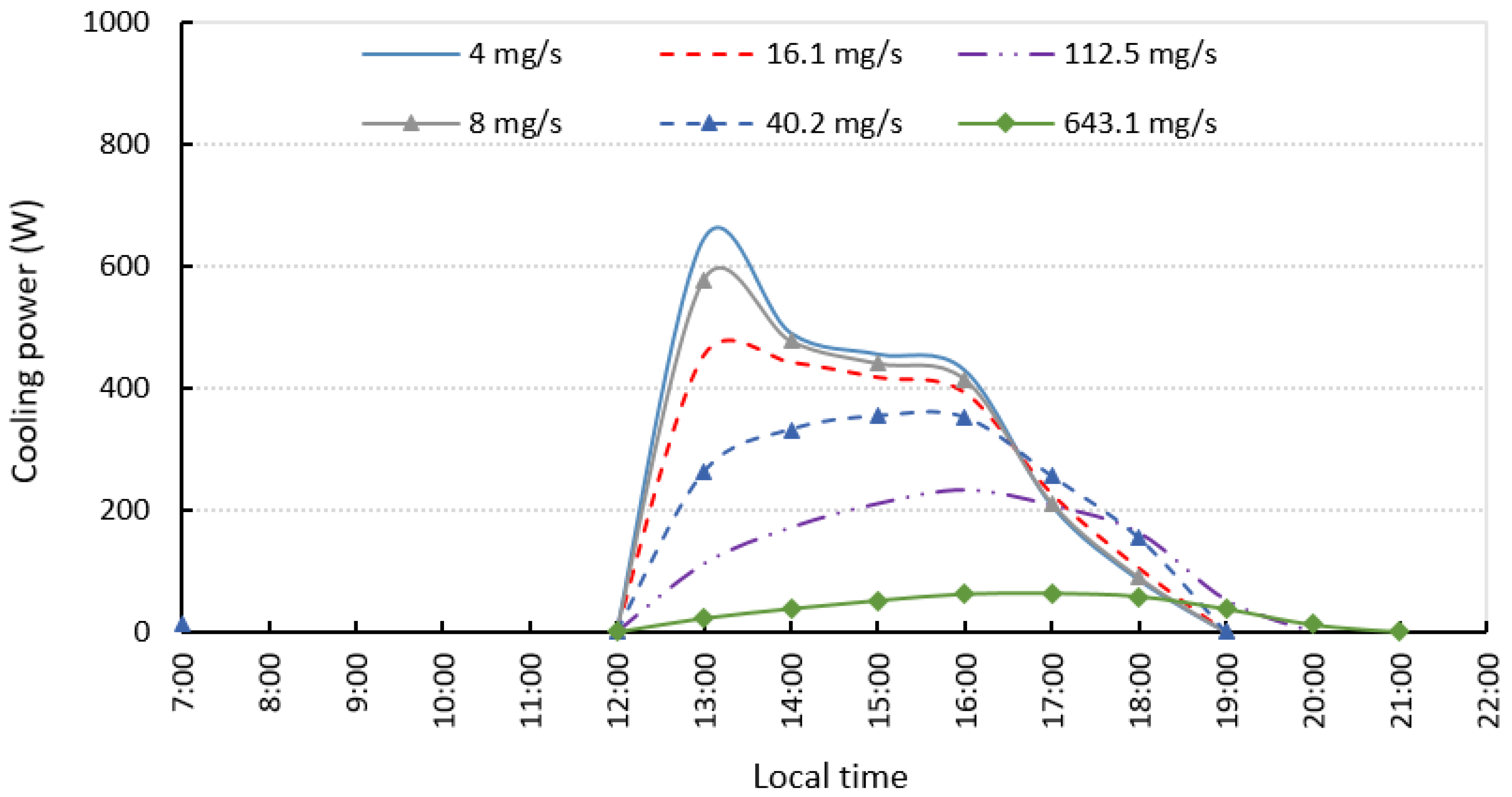
Mass Flow Rate through the Channels (mg/s)Number of Desorber Modules (with Data of Table 1)
4588
8294
16.1147
40.258.8
112.521
643.1 3.7

