Article

Real-Time FPGA-Based Balance Control Method for a Humanoid Robot Pushed by External Forces

Department of Electrical and Computer Engineering, Tamkang University, New Taipei City 25137, Taiwan
*
Author to whom correspondence should be addressed.
Appl. Sci. 2020, 10(8), 2699; https://doi.org/10.3390/app10082699
Submission received: 28 February 2020 / Revised: 2 April 2020 / Accepted: 9 April 2020 / Published: 14 April 2020
(This article belongs to the Special Issue Bio-Inspired Robotics II)

Abstract

:
In this paper, a real-time balance control method is designed and implemented on a field-programmable gate array (FPGA) chip for a small-sized humanoid robot. In the proposed balance control structure, there are four modules: (1) external force detection, (2) push recovery balance control, (3) trajectory planning, and (4) inverse kinematics. The proposed method is implemented on the FPGA chip so that it can quickly respond to keep the small-sized humanoid robot balanced when it is pushed by external forces. A gyroscope and an accelerometer are used to detect the inclination angle of the robot. When the robot is under the action of an external force, an excessively large inclination angle may be produced, causing it to lose its balance. A linear inverted pendulum with a flywheel model is employed to estimate a capture point where the robot should step to maintain its balance. In addition, the central pattern generators (CPGs) with a sinusoidal function are adopted to plan the stepping trajectories. Some experimental results are presented to illustrate that the proposed real-time balance control method can effectively enable the robot to keep its balance to avoid falling down.

1. Introduction

Compared with wheeled robots, a biped structure and excellent athletic ability are given to humanoid robots. Many biped robot algorithms have been developed, such as balance control and inverse kinematics [1,2,3]. The zero moment point (ZMP) and walking dynamics analysis can be adopted to enable a robot to walk steadily [4,5,6,7]. However, these methods require copious calculations; researchers must develop an approximate or simple dynamic model. However, because to an oversimplified dynamic model would result in estimation errors, an appropriate approximation model is needed to guarantee steady walking gaits. A linear inverted pendulum model [8,9] was proposed, and developed a preview control which is integrated ZMP to modify for errors caused by the simplified model [10,11]. However, the aforementioned methods cannot be applied to many small-sized humanoid robots that have limited computing capacities. Therefore, some biologically-inspired controls based on neural systems were proposed. The central pattern generators (CPGs) have been utilized to affect the movement of biological rhythms. Motor neurons produce spontaneous and steady oscillation signals through mutual inhibition networks and constant activation. The regular rhythmic motion is produced by the steady walking gaits so that the characteristics of the oscillator are suitable for presenting CPGs in the workspace [12]. Through the status of the self or feedback from the environment, motion models can be adjusted. Several kinds of research have employed ZMP or attitude estimation to examine whether the robot motion followed the walking model created by CPGs [13], and the motion was adjusted to maintain balance [14]. Additionally, some kinds of research have proposed to control dynamic changes of the robot by utilizing the center of mass (COM) and center of pressure (COP) [15,16]. The walking method is also a kind of swinging behavior [17], which can be generated by an oscillator model, and can be composed by the left and right foot stepping [18]. Hence, the stepping gait can be described by the oscillator parameters. These studies have enabled robots to achieve ideal dynamic models. Similarly, CPGs have created ideal walking models and sensor compensations to enable robots to walk steadily.
When an external force is strong enough to let the robot lose its balance and fall, the proposed balance control method will be enabled to compute against this unstable state. This proposed method is derived from the linear inverted pendulum model by incorporating a flywheel [19,20] to avoid falling down, especially in the sagittal direction, which can swing greatly. When the robot is affected by a reasonable external force, a position on the ground, called the capture point, can be found to keep its balance. If the robot stretches out a foot and steps on that capture point, then balance can be regained. The proposed balance control method was completely tested on a real small-sized humanoid robot, and only one impact on the robot was adopted to illustrate its performance. There were also some simulations of humanoid robots [21,22], and simulations of push recovery balance control [23,24], but the verification data of real operation is scarce. The balance control system of the real robot is further implemented in this paper.
The rest of this paper is organized as follows. In Section 2, a small-sized humanoid robot, which is used as an experimental platform for the proposed control method, and its specifications, are described. In Section 3, the main system architecture of this robot and the module structure of the proposed balance control method implemented on an FPGA (field-programmable gate array) chip are described. In Section 3.1, a gyroscope and an accelerometer are attached on the waist of the robot to measure its inclination angle. The Kalman filter is used to reduce the influence caused by the noise and detect the external force. In Section 3.2, a linear inverted pendulum with a flywheel model is presented, and a capture point is calculated according to the measured inclination angle. When the humanoid robot is under an external force, a capture point can be determined based on the impact force and its direction. In Section 3.3, the CPGs are adopted for the stepping gait of the humanoid robot. The obtained capture point is used to be an input to generate stepping trajectories through a sinusoidal function. In Section 3.4, joint angles of each motor are calculated based on the inverse kinematics. In Section 4, some experimental results are presented. Finally, the paper is summarized in Section 5.

2. Small-Sized Humanoid Robot

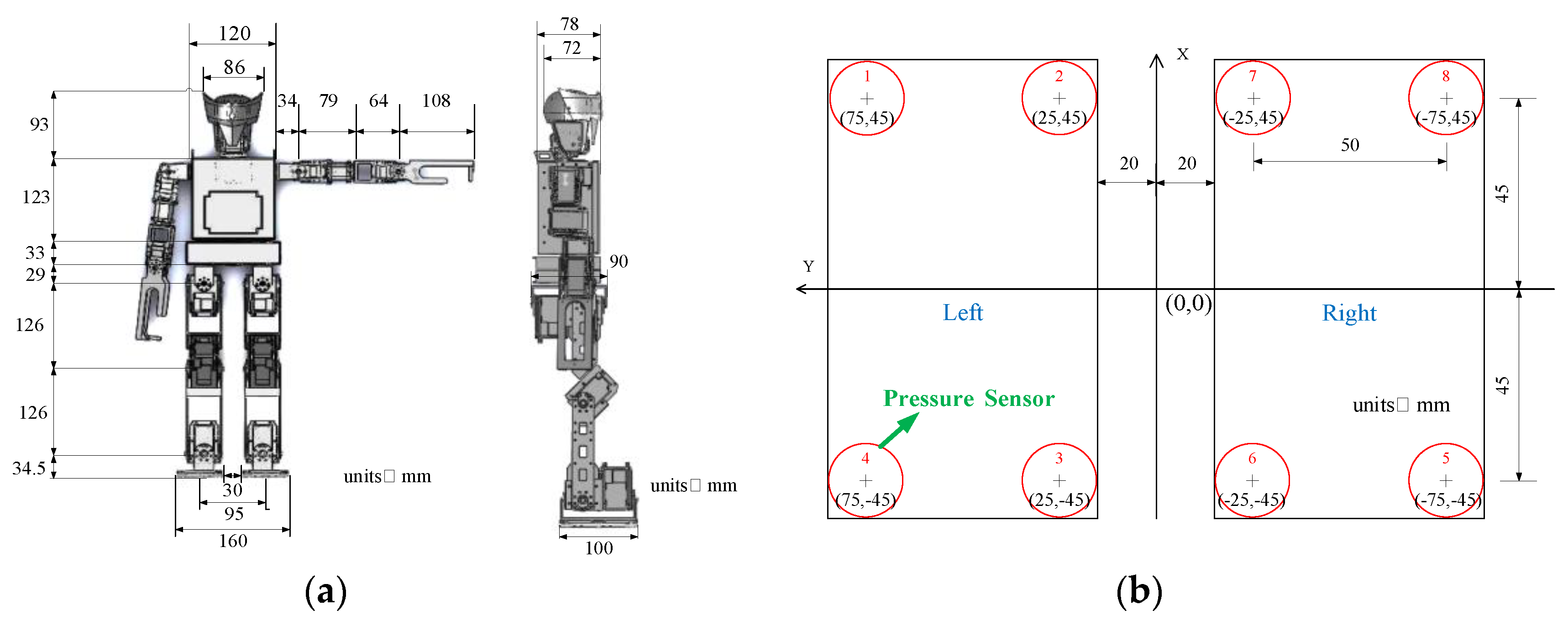
A small-sized humanoid robot named “TKU-X” was developed by our laboratory and used to perform the proposed balance control method. As shown in Figure 1, it has 23 degrees of freedom (DOFs). A CMOS sensor is installed on the head so that it can be a vision-based autonomous robot. The planning of 2 DOFs for the head is to enable the CMOS sensor to move up-and-down and left-and-right to capture information about the surrounding environment of the robot in a wide range. The planning of 1 DOF for the waist is to enable the robot to do more movements to enhance its view. Moreover, the planning of 4 DOFs for one arm and 6 DOFs for one leg is to enable the robot to grasp objects and walk flexibly. The mechanism’s size and the overall specifications of the TKU-X are respectively shown in Figure 2 and Table 1. Its height and weight are 564.5 mm and 4.5 kg, respectively. The main hardware includes 23 servo motors, 1 CMOS (complementary metal–oxide–semiconductor) sensor, 1 gyroscope, 1 accelerometer, 8 pressure sensors, 1 FPGA board, and 1 integrated circuit board. A gyroscope and an accelerometer are attached on the waist of the robot to measure its inclination angle, and four pressure sensors are installed per sole of foot, in the corners [1,4], to measure the ZMP. Through the designed integrated circuit board, this FPGA board can be connected to all device components (such as servo motors, gyroscope, accelerometer, and pressure sensors) by using GPIO (general-purpose input/output) pins. FPGA chips have the advantages of parallel processing and low power consumption. Therefore, compared to the Darwin-OP robot with an Arduino board [9,13], TKU-X with this FPGA board has more significant computing and real-time processing capabilities.
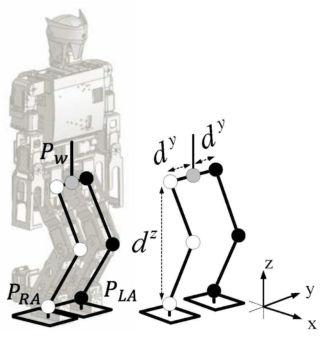
The diagram of the legs of TKU-X and its coordinate system are shown in Figure 3, where P W = ( P W x , P W y , P W z ) is the position of the waist. P R A = ( P R A x , P R A y , P R A z ) and P L A = ( P L A x , P L A y , P L A z ) are the ankle positions of the right foot and the left foot, respectively. The humanoid robot exchanges the right foot for the left foot as the supporting foot, and vice versa, to gain the ability to walk. d y is the distance between the waist P W and the hip joint. d z is the distance between the hip joint and the ankle joint.

3. FPGA-Based Balance Control Method

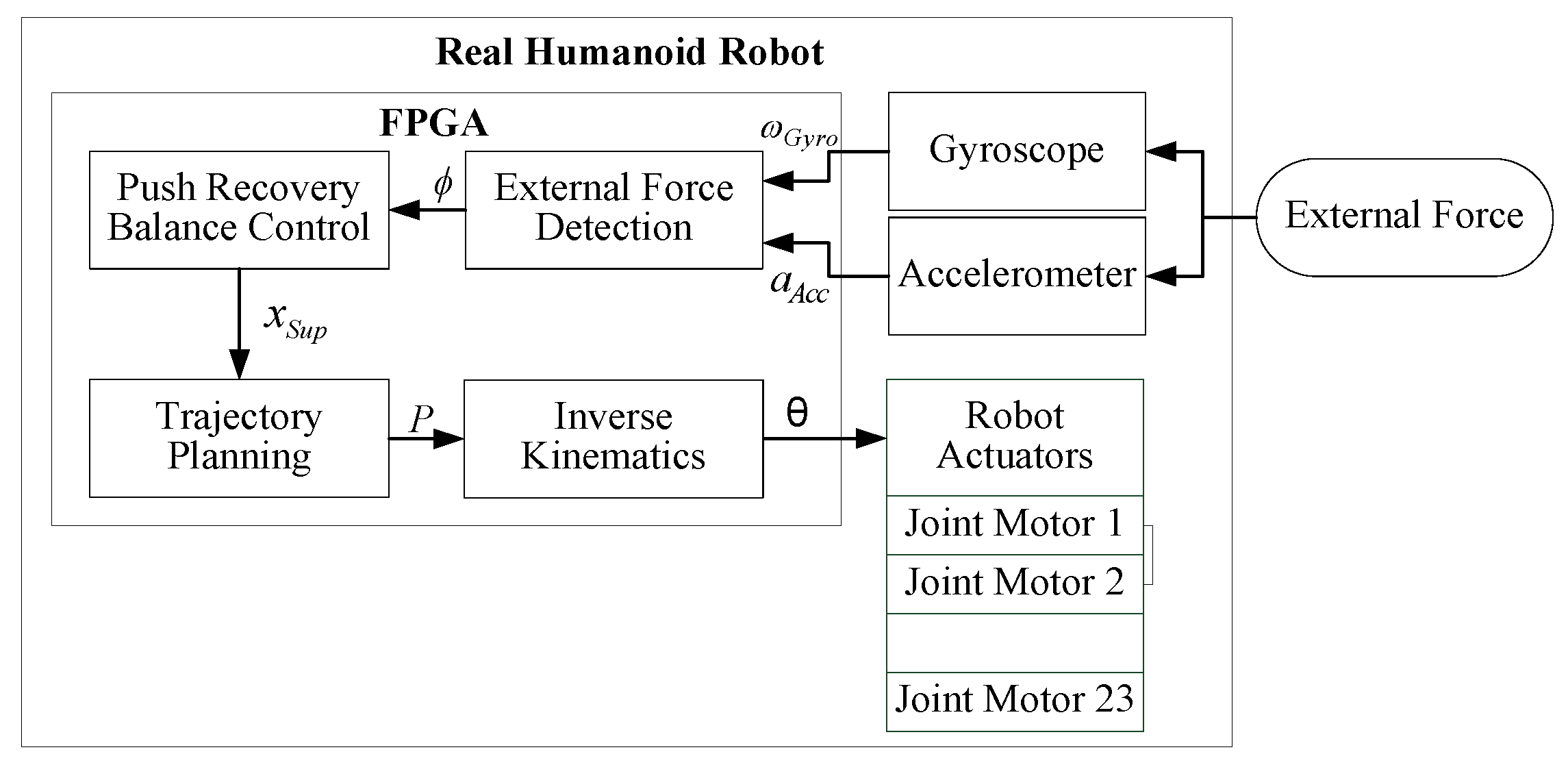
A real-time FPGA-based balance control method is proposed for small-sized humanoid robots so that it can quickly respond to keep the robot in balance when it is pushed by external forces. The descriptions of the input/output of the executing process from sensors to actuators and the four modules of the proposed balance control method implemented on the FPGA chip are described in Figure 4. The procedure of these four modules for one-time at the moment of impact can be described as follows: (1) External force detection module: a gyroscope and an accelerometer are used to detect the moment of impact and an inclination angle ϕ of the robot, which represent the strength of the external force; they are obtained from the external force detection module based on the measured sensor information ( ω G y r o , a A c c ) . (2) Push recovery balance control module: When a large enough external force is measured, a capture point x S u p is calculated from the push recovery balance control module based on the received inclination angle ϕ . The capture point x S u p is defined as a position on the ground at which the robot can step to regain its balance when the humanoid robot is under the external force. (3) Trajectory planning module: the stepping trajectories P = ( P R A , P L A ) are determined from the trajectory planning module based on the obtained capture point x S u p to let the robot can stretch out its foot. (4) Inverse kinematics module: The joint angles θ are determined form the inverse kinematics module based on the planned stepping trajectories P until the robot steps on the capture point x S u p . The details of these four modules are described as follows.

3.1. External Force Detection

The external force detection module is proposed and implemented to estimate an inclination angle ϕ of the robot based on the sensor information ( ω G y r o , a A c c ) obtained from the gyroscope and accelerometer mounted on TKU-X robot. The information obtain from these two sensors is employed to infer the stepping strategy with which the humanoid robot could step to regain its balance. Because the value ω G y r o measured by the gyroscope will gradually diverge with time and the value a A c c measured by the accelerometer will also change significantly when the robot swings, the Kalman filter [25,26] shown in Figure 5 is used to integrate the sensor information ( ω G y r o , a A c c ) obtained from the gyroscope and accelerometer to calculate a more accurate inclination angle ϕ . The main formulas are described by
ϕ ( t ) = A ϕ ( t 1 ) + B ω G y r o ( t ) + w ( t )
a A c c ( t ) = H ϕ ( t ) + v ( t )
where A, B, and H are the state transition matrix, the control input matrix, and the transformation matrix, respectively. ϕ ( t ) is the state at time t is evolved from the state ϕ ( t 1 ) at time t 1 . ω G y r o ( t ) is the control input which is measured by the gyroscope and a A c c ( t ) is the measurement which is measured by the accelerometer. w ( t ) and v ( t ) are, respectively, the process noise and the measurement noise.
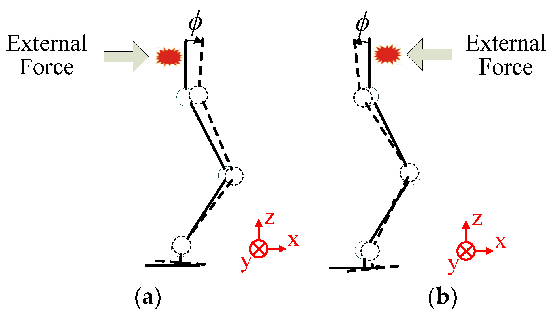
As shown in Figure 6, when the humanoid robot is subjected to an external force from the back or the front, an inclination angle ϕ of the robot with respect to the vertical ground is generated. This inclination angle ϕ is used to reflect the strength of this external force. A small value ϕ means this external force does not have a significant impact on the robot, and a large value ϕ indicates this external force may cause the robot to fall down and no longer be balanced. Therefore, if the external force comes from the back, a forward balance strategy is proposed so that the robot will take a step forward to maintain balance. Conversely, if the external force comes from the front, a backward balance strategy is proposed so that the robot will take a step backward to maintain balance.

3.2. Push Recovery Balance Control

The push recovery balance control module is proposed and implemented to determine the capture point x S u p based on the inclination angle ϕ obtained by the external force detection module to let the humanoid robot maintain balance under an external force. When a human is suddenly hit by a large external force, it is natural for this human to immediately swing the leg to maintain balance. Therefore, a linear inverted pendulum with a flywheel model, as shown in Figure 7, is used to calculate the capture point x S u p . The motion equations are defined as follows:
x ¨ C O M = g h x C O M 1 m h τ
θ ¨ b = 1 J τ
where m is the center of mass (COM), h is the height of mass, g is the gravitational acceleration constant, l is the length of the leg, f is the force at the support point, τ is the motor torque on the flywheel, and J is the rotational inertia of the flywheel. x C O M is the COM of the robot and θ b is the flywheel angle with respect to the vertical direction.
When a humanoid robot is under an external force, suppose the upper body of the robot does not rotate. Therefore, the motor torque on the flywheel τ is set as 0 to maintain the original pose of the upper body and find the capture point. An orbital energy E L I P is defined to represent the torque τ [19,20] and it can be expressed by
E L I P = 1 2 x ˙ C O M 2 g 2 h ( x C O M x S u p ) 2
when E L I P = 0, the robot will keep its balance. Thus, the capture point x S u p can be computed by
x S u p = x C O M + x ˙ C O M h g
A linear inverted pendulum model is also applied to require the COM state of the robot which would be generated based on the obtained inclination angle ϕ . Therefore, x C O M and x ˙ C O M can be described by
x C O M = l sin ( ϕ )
and
x ˙ C O M = l cos ( ϕ ) ϕ ˙
According to the energy conservation law, the kinetic energy can be represented by
1 2 m l 2 ϕ ˙ 2 = m g l ( 1 cos ( ϕ ) )
The velocity of the inclination angle ϕ ˙ of the robot can be required as follows:
ϕ ˙ = 2 g l ( 1 cos ( ϕ ) )
Thus, the capture point x S u p can be determined by substituting x C O M and x ˙ C O M into Equation (6). The capture point x S u p is used to calculate the step length based on the strength of the external force which is presented by the inclination angle ϕ . The safety thresholds, ε 1 and ε 2 , are set to compare with the external force which is detected from the COM of the humanoid robot through a gyroscope and an accelerometer. If the detected external force is more than ε 1 or less than − ε 2 , the positive or negative value of x S u p will be obtained to execute the forward or backward balance strategies, and then the robot will take a step to resist the external force. In contrast, if the detected external force is between ε 1 and − ε 2 , the robot will just maintain its standing posture. The pseudo code of the proposed push recovery balance control is shown in Algorithm 1.
Algorithm 1 Pseudo code of the proposed push recovery balance control.
Method: Push Recovery Balance Control.
Initialize the safety thresholds ε 1 and ε 2
ϕ ← Update from a gyroscope and an accelerometer
if ( ϕ > ε 1 ) or ( ϕ < − ε 2 ) then
ϕ ˙ = 2 g ( 1 cos ( ϕ ) ) / l
x C O M = l sin ( ϕ )
x ˙ C O M = l cos ( ϕ ) ϕ ˙
x S u p = x C O M + x ˙ C O M h / g
else
x S u p = 0
end

3.3. Trajectory Planning

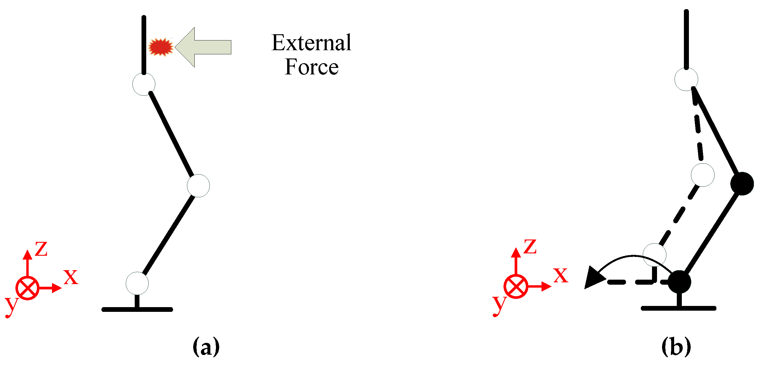
The trajectory planning module is proposed and implemented to determine the stepping trajectories P = ( P R A , P L A ) based on the obtained capture point x S u p by the push recovery balance control module. When a humanoid robot is subjected to a sufficiently strong external force to make it impossible to balance in a standing posture, like a human, the robot will take a step to maintain its balance and prevent it from falling. As shown in Figure 8a, when the robot receives an external force from its back in the standing posture, the forward balance strategy is executed. The robot’s right foot is on the floor but its left foot lifts and swings forward one step, as shown in Figure 8b. Similarly, as shown in Figure 9a, when the robot receives an external force from its front in the standing posture, the backward balance strategy is executed. The robot’s right foot is on the floor but its left foot lifts and swings backward one step, as shown in Figure 9b.
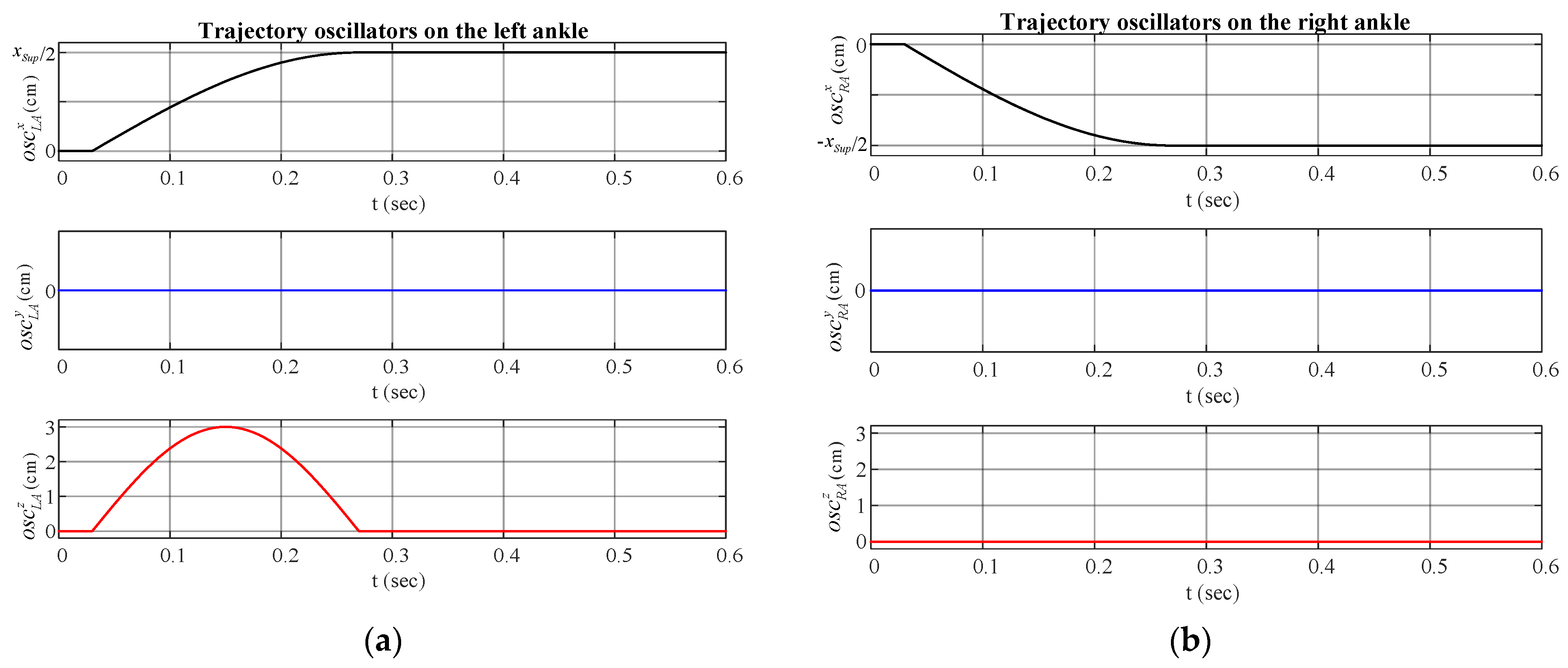
The central pattern generators (CPGs) based on a simplified coupled linear oscillator model are adopted for producing the stepping gait to design the desired stepping trajectories P = ( P R A , P L A ) through the simplified sinusoidal function. All sets of coordinates represent the relative positions of different oscillators to the position of the waist P W , which is denoted as the origin. P R A and P L A are respectively the positions of the right foot and the left foot in the space and described by
P R A = o s c R A + p R A 0 = ( o s c R A x , o s c R A y , o s c R A z ) + ( 0 , d y , d z )
and
P L A = o s c L A + p L A 0 = ( o s c L A x , o s c L A y , o s c L A z ) + ( 0 , d y , d z )
where o s c R A and o s c L A are the trajectory oscillators on the right and left ankle, respectively. p R A 0 and p L A 0 are the starting points of the right and left ankles, respectively. d y is the distance between the position of the waist P W and the hip joint. d z is the distance between the hip joint and the ankle joint. Moreover, these two trajectory oscillators o s c R A = ( o s c R A x , o s c R A y , o s c R A z ) and o s c L A = ( o s c L A x , o s c L A y , o s c L A z ) , are represented by
o s c R A x = { 0 , i f   t [ 0 , γ T 2 ) ρ R A x sin ( ω R A x ( t T 2 γ ) + φ R A x ) , i f   t [ γ T 2 , T γ T 2 ) ρ R A x , i f   t [ T γ T 2 , T )
and
o s c R A y = { 0 , i f   t [ 0 , γ T 2 ) ρ R A y sin ( ω R A y ( t T 2 γ ) + φ R A y ) , i f   t [ γ T 2 , T γ T 2 ) 0 , i f   t [ T γ T 2 , T )
o s c R A z = { 0 , i f   t [ 0 , γ T 2 ) ρ R A z sin ( ω R A z ( t T 2 γ ) + φ R A z ) , i f   t [ γ T 2 , T γ T 2 ) 0 , i f   t [ T γ T 2 , T )
o s c L A x = { 0 , i f   t [ 0 , γ T 2 ) ρ L A x sin ( ω L A x ( t T 2 γ ) + φ L A x ) , i f   t [ γ T 2 , T γ T 2 ) ρ L A x , i f   t [ T γ T 2 , T )
o s c L A y = { 0 , i f   t [ 0 , γ T 2 ) ρ L A y sin ( ω L A y ( t T 2 γ ) + φ L A y ) , i f   t [ γ T 2 , T γ T 2 ) 0 , i f   t [ T γ T 2 , T )
o s c L A z = { 0 , i f   t [ 0 , γ T 2 ) ρ L A z sin ( ω L A z ( t T 2 γ ) + φ L A z ) , i f   t [ γ T 2 , T γ T 2 ) 0 , i f   t [ T γ T 2 , T )
where t is the time and T is a period of time. γ , ρ , ω , and φ are the double support phase ratio, the amplitude, the frequency, and the starting phase of oscillator parameters, respectively.
As shown in Table 2, the oscillator parameters of the stepping gait are taken to execute the forward and backward balance strategies. ρ R A x ( ρ L A x ), ρ R A y ( ρ L A y ), and ρ R A z ( ρ L A z ) are the step length, step width, and lifting height of the right (left) foot, respectively. ω R A x ( ω L A x ), ω R A y ( ω L A y ), and ω R A z ( ω L A z ) are the frequencies of the right (left) foot. φ R A x ( φ L A x ), φ R A y ( φ L A y ), and φ R A z ( φ L A z ) are the phase differences of the right (left) foot. In this paper, the oscillator parameters T and γ are set as 0.3 s and 0.2, respectively. Moreover, the lifting height H S u p of the foot is set as 3 cm when the robot takes this stepping gait. For example, in the stepping trajectories of the forward balance strategy for the robot taking a step, two trajectory oscillators on the right and left ankle are shown in Figure 10 based on the results described in Equations (13)–(18).

3.4. Inverse Kinematics

The inverse kinematics module is proposed and implemented to determine the joint angles θ based on the obtained stepping trajectories P = ( P R A , P L A ) by the trajectory planning module so that the robot can step out its foot to maintain balance. A humanoid robot has an ability to move with its feet to the next location. The stepping trajectories P = ( P R A , P L A ) are particular points of the right and left foot in the space. Therefore, the inverse kinematics are used to calculate the angle at which each joint should be rotated. The joint angles θ can be solved through the relationship between links and joints of the robot to reach those particular points in the space.
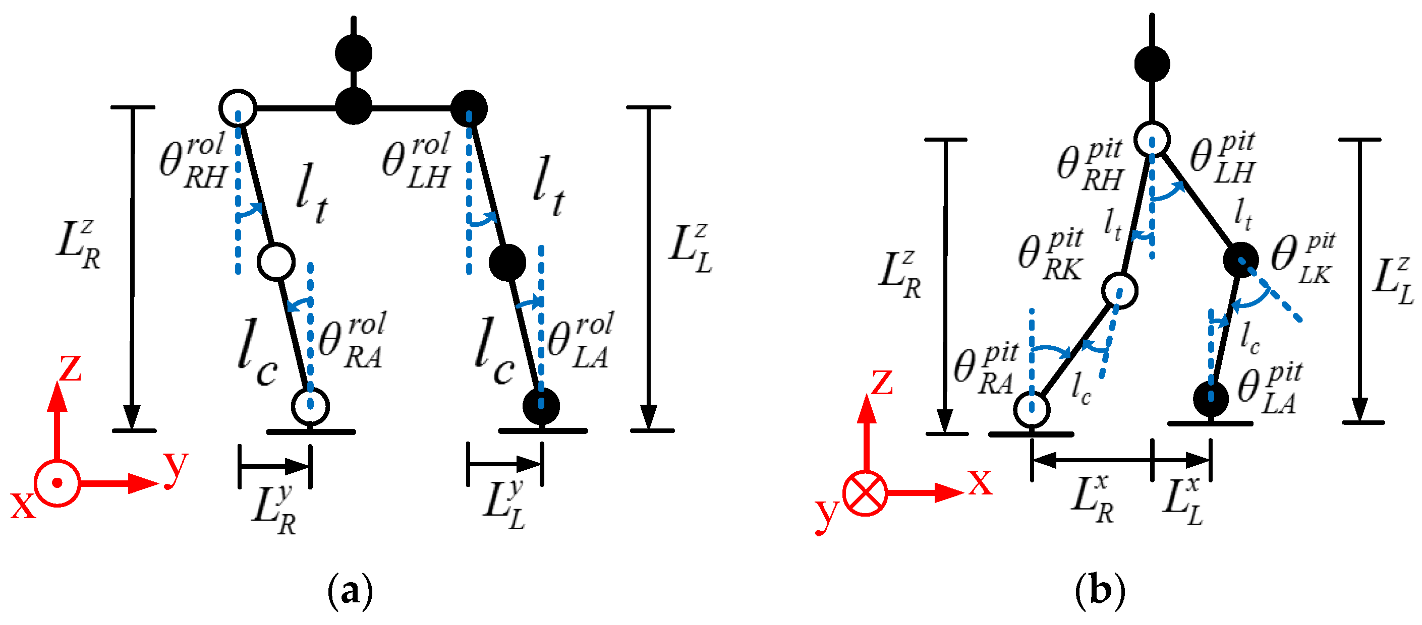
The link coordinate system of the humanoid robot is shown in Figure 11, where l t and l c are respectively the lengths of the robot’s thigh link and calf link, and L R x ( L L x ), L R y ( L L y ), and L R z ( L L z ) are respectively the step length, step width, and lift height of the right (left) foot. Observed from the front of the robot, θ R H r o l ( θ L H r o l ) and θ R A r o l ( θ L A r o l ) are the angles of the hip joint and ankle joint of the right (left) foot, respectively. Observed from the right side of the robot, θ R H p i t ( θ L H p i t ), θ R K p i t ( θ L K p i t ), and θ R A p i t ( θ L A p i t ) are the angles of the hip joint, knee joint, and ankle joint of the right (left) foot, respectively.
Based on the link coordinate system in Figure 11a and the inverse kinematics, θ R H r o l , θ R A r o l , θ L H r o l , and θ L A r o l can be respectively obtained from L R y , L R z , L L y , and L L z . They are described as follows:
θ R H r o l = tan 1 ( L R y L R z )
θ R A r o l = θ R H r o l
θ L H r o l = tan 1 ( L L y L L z )
and
θ L A r o l = θ L H r o l
Similarly, based on the link coordinate system in Figure 11b and the inverse kinematics, θ R H p i t , θ R K p i t , θ R A p i t , θ L H p i t , θ L K p i t , and θ L A p i t can be respectively obtained from L R x , L R z , L L x , and L L z . They are described as follows:
θ R H p i t = cos 1 ( L R x 2 + L R z 2 + l t 2 l c 2 2 l t L R x 2 + L R z 2 ) + tan 1 ( L R x L R z )
θ R K p i t = π tan 1 ( l t cos ( θ R H p i t ) l t sin ( θ R H p i t ) ) tan 1 ( L R z l t cos ( θ R H p i t ) l t sin ( θ R H p i t ) L R x )
θ R A p i t = tan 1 ( l t sin ( θ R H p i t ) L R x L R z l t cos ( θ R H p i t ) )
θ L H p i t = cos 1 ( L L x 2 + L L z 2 + l t 2 l c 2 2 l t L L x 2 + L L z 2 ) + tan 1 ( L L x L L z )
θ L K p i t = π tan 1 ( l t cos ( θ L H p i t ) l t sin ( θ L H p i t ) ) tan 1 ( L L z l t cos ( θ L H p i t ) l t sin ( θ L H p i t ) L L x )
and
θ L A p i t = tan 1 ( l t sin ( θ L H p i t ) L L x L L z l t cos ( θ L H p i t ) )
Thus, the joint angles described by Equations (19)–(28) are required for the humanoid robot to achieve stability through the proposed balance control method.

4. Experimental Results

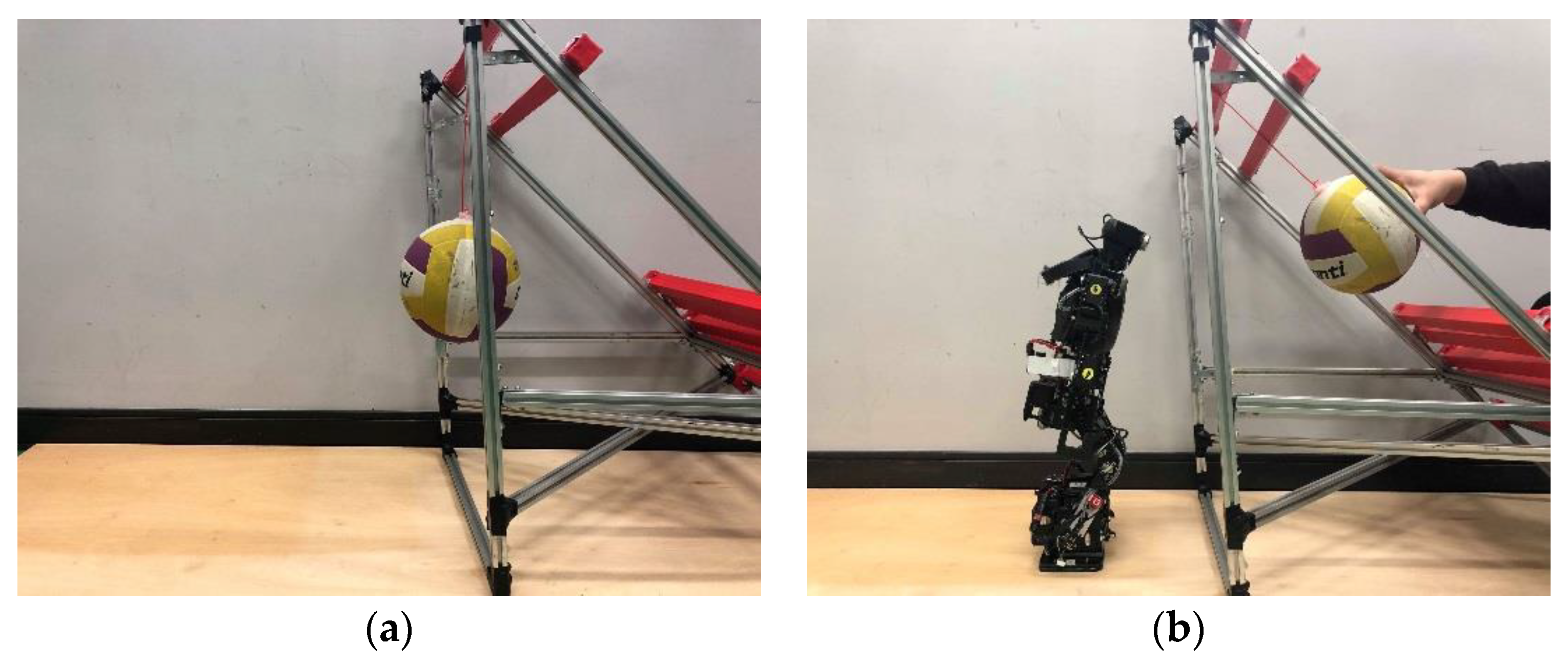
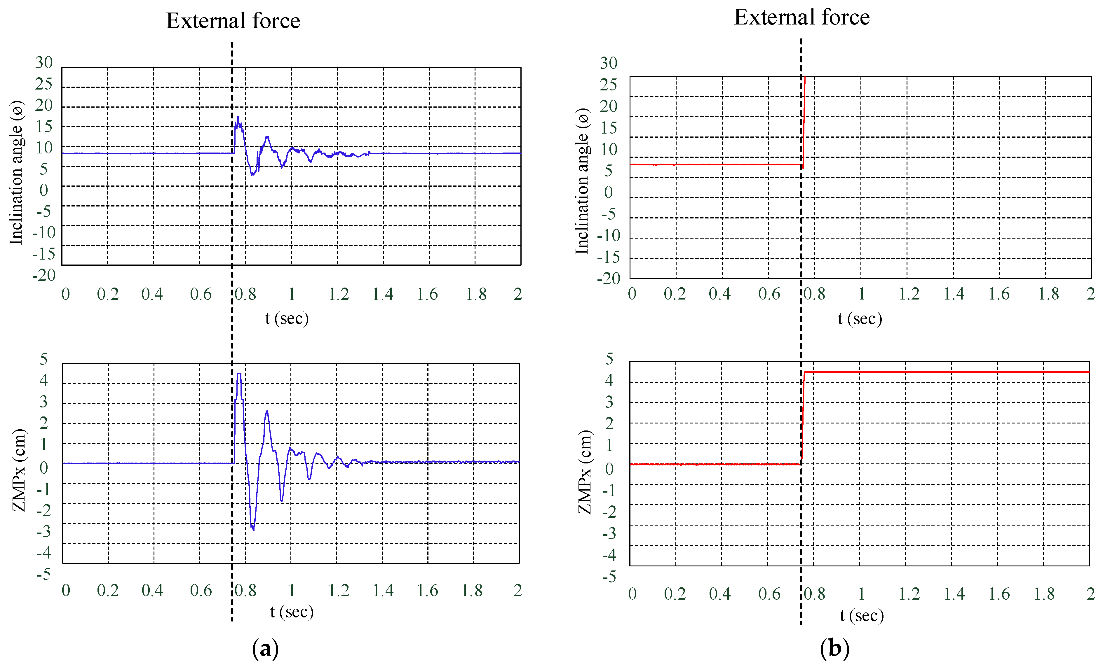
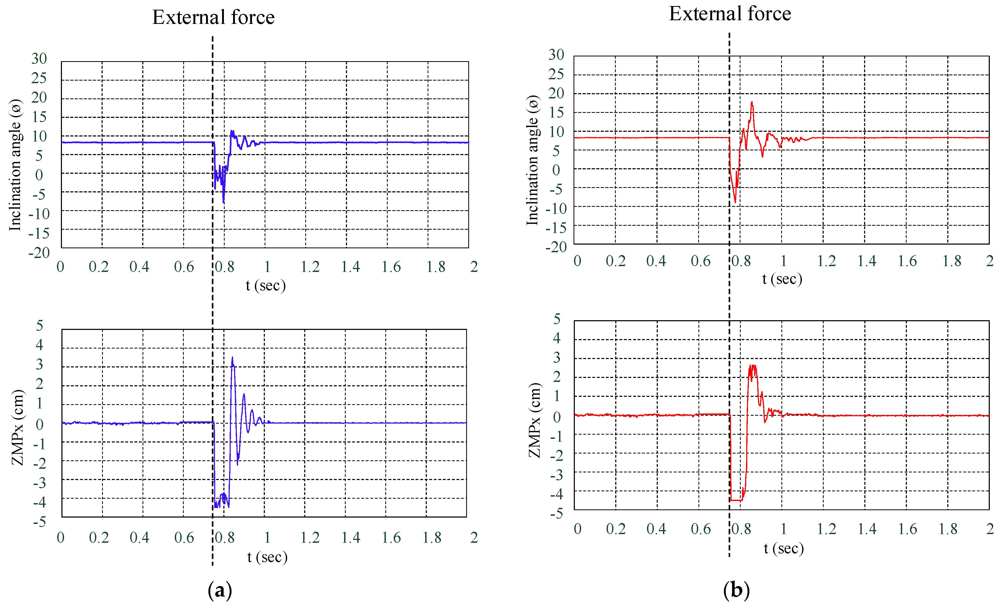
The performance of the proposed balance control method is illustrated in this section. The sampling time used in the experiment is 30 ms. Owing to the TKU-X robot failing to remain standing and balanced by itself when it is hit by an impact force of 0.93 N, that force is viewed as the maximum external force for the robot in this experiment. An experimental platform is constructed and shown in Figure 12, wherein a baseball or a volleyball is respectively raised to 45° and released to hit the TKU-X robot. As listed in Table 3, two different impact forces of 0.47 N and 0.93 N on the robot are respectively produced by the baseball and volleyball. When the TKU-X robot is in its standing posture, its upper body leans forward about 7°. When the inclination angle of the TKU-X robot is within (−2, 12), it can stably walk. Hence, the safety thresholds ε 1 and − ε 2 are set to be ε 1 = 12 and − ε 2 = −2 in this experiment. The results of the inclination angle ϕ (pitch-axis) and ZMP (x-axis) are shown form Figure 13, Figure 14, Figure 15 and Figure 16 when the balance control method is disabled and enabled. There are two kinds of experiments: (1) Balance control with stepping forward, and (2) balance control with stepping backward. They are described as follows:

4.1. Balance Control with Stepping Forward

In this experiment, the TKU-X robot is hit from the back by a baseball or a volleyball at 0.75 s. When the balance control method is disabled and enabled, the experimental results are respectively shown in Figure 13 and Figure 14. The initial values of the inclination angle ϕ (pitch-axis) and ZMP (x-axis) are 7° and 0, respectively. When the balance control method is disabled, the experimental results of the TKU-X robot hit from the back by a baseball and a volleyball are shown in Figure 13a,b, respectively. As shown in Figure 13a, the data reveal that the robot wavers back and forth substantially and needs about 0.6 s to converge to its stable state. As shown in Figure 13b, because the impact force produced by the volleyball is 0.93 N, the data reveal that the robot instantly falls down to the ground and fails to remain standing and balance. When the balance control method is enabled, the experimental results of the TKU-X robot hit from the back by a baseball and a volleyball are shown in Figure 14a,b, respectively. As shown in Figure 14a, because the external force is from the back of the robot, the values of the inclination angle ϕ (pitch-axis) and ZMP (x-axis) increase from 7° and 0, respectively. When the safety threshold ε is exceeded by the inclination angle ϕ , a capture point x S u p is calculated. During the period when the robot stretches out its foot to the capture point and steps on the capture point, the values of the inclination angle ϕ (pitch-axis) and ZMP (x-axis) decrease and return to 7° and 0, respectively. Because the impact force produced by the baseball is 0.47 N, the TKU-X robot takes a step forward about 1.36 cm to maintain balance. In this experiment of the TKU-X robot is hit by a baseball from the back; the recovery time of the enabled control method takes about 0.25 s, which is 2.4 times faster than the disabled control method to return to a stable state. Similarly, as shown in Figure 14b, because the impact force produced by the volleyball is 0.93 N, the TKU-X robot takes a step forward 4.15 cm to maintain balance. In this experiment of the TKU-X robot being hit by a volleyball from the back, the recovery time of the enabled control method is about 0.25 s (for a successful return to a stable state), which is not realized when the control method is disabled. Some experimental results are shown in Table 4 when the proposed balance control method with the stepping forward is enabled or disabled for the TKU-X robot. The video can be viewed on the website: https://youtu.be/h2psoR5T3eo.

4.2. Balance Control with Stepping Backward

The experimental results of the TKU-X robot being hit from the front by a baseball or a volleyball at 0.75 s when the balance control method is disabled and enabled are respectively shown in Figure 15 and Figure 16. When the balance control method is disabled, the experimental results of the TKU-X robot hit from the front by a baseball and a volleyball are respectively shown in Figure 15a,b. Similarly, the data reveal that the robot wavers back and forth substantially and needs about 0.65 s to converge to the stable state in Figure 15a. To compare Figure 13b with Figure 15b, the TKU-X robot falling down is shown in Figure 13b, but the TKU-X robot taking about 0.97 s to recover the stable state is shown in Figure 15b. The difference between falling and standing is that the upper body of TKU-X robot leans forward about 7°. When the balance control method is enabled, the experimental results of the TKU-X robot hit from the front by a baseball and a volleyball are respectively shown in Figure 16a,b. As shown in Figure 16, because the external force is from the front of the robot, the values of the inclination angle ϕ (pitch-axis) and ZMP (x-axis) decrease from 7° and 0, respectively. Similarly, when the safety threshold ε is exceeded by the inclination angle ϕ , a capture point x S u p is calculated. During the period when the robot stretches out its foot to the capture point, the values of the inclination angle ϕ (pitch-axis) and ZMP (x-axis) increase. Finally, when the robot steps on the capture point, the stable state can be regained; the values of the inclination angle ϕ (pitch-axis) and ZMP (x-axis) return to 7° and 0, respectively. Because the impact forces produced by the baseball and the volleyball are 0.47 and 0.93 N, the TKU-X robot respectively takes steps backward of about 1.09 cm and 3.88 cm to maintain balance. In this experiment of the TKU-X robot is hit by a baseball and volleyball from the front, the recovery times of the enabled control method are about 0.20 and 0.37 s—3.25 times and 2.62 times, respectively, faster than the disabled control method to return to a stable state. Some experimental results are shown in Table 5 when the proposed balance control method with the stepping backward is enabled or disabled for the TKU-X robot. The video can be viewed on the website: https://youtu.be/86lTwziQA2I.

5. Conclusions

In this paper, a lightweight balance control method is proposed and embedded in an FPGA chip for the fastest possible response, and a complete implementation of the push recovery on a real robot is presented. There are four main contributions of this research. Firstly, an external force detection method is realized and used to estimate an inclination angle of the robot by the sensor information. According to the inclination angle, not only can the strength of an external force be obtained, but the stepping strategy can be determined also. Secondly, a push recovery balance control method is proposed and implemented based on a linear inverted pendulum with a flywheel model to enable the humanoid robot to regain its balance when a strong enough external force is measured by the proposed external force detection method. Thirdly, a trajectory planning method is designed and combined with the proposed push recovery balance control method so that the capture point can be directly related to the oscillator parameters of the stepping gait, and it can be used simultaneously to execute the stepping trajectories of the forward or backward balance strategies. Then an inverse kinematics method is applied to obtain the joint angles from the proposed trajectory planning method to enable the humanoid robot to stretch out its foot to the capture point. Lastly, a system architecture of the proposed balance control method is implemented on an FPGA chip, which can respond immediately to allow the robot to continue to balance without falling. The proposed balance control method is completely tested on a real small-sized humanoid robot, TKU-X. Several experiments under different forces and directions are presented to verify the performance of the proposed method. A baseball and a volleyball are respectively used to hit TKU-X to produce two difference forces of 0.47 and 0.93 N. Two different kinds of balls not only hit from the front but also from the back. From the experimental results of successful balance, the real-time feasibility of the proposed balance control method is demonstrated. Hence, a stable state can be effectively recovered for the humanoid robot which is pushed by an external force. In future work, the proposed real-time FPGA-based balance control method could be applied during walking and for multiple impacts. Moreover, it could also be employed to overcome varying terrain, such as when climbing uphill, going downhill, or walking on uneven surfaces.

Author Contributions

Conceptualization, T.-T.L., C.-C.W., and C.-C.L.; formal analysis, C.-C.W.; investigation, S.-R.X. and Y.-Y.L.; methodology, S.-R.X., Y.-Y.L., and Y.-C.L.; software, S.-R.X., Y.-Y.L., and Y.-C.L.; writing—original draft, C.-C.L. and S.-R.X.; writing—review and editing, T.-T.L. and C.-C.W. All authors have read and agreed to the published version of the manuscript.

Funding

This paper was partly supported by the Ministry of Science and Technology (MOST) of the Republic of China under contract MOST 107-2221-E-032-048 and MOST 108-2221-E-032-044.

Conflicts of Interest

The authors declare no conflict of interest.

References

  1. Li, T.H.S.; Su, Y.T.; Liu, S.H.; Hu, J.J.; Chen, C.C. Dynamic balance control for biped robot walking using sensor fusion, Kalman filter, and fuzzy logic. IEEE Trans. Ind. Electron. 2012, 59, 4394–4408. [Google Scholar] [CrossRef]
  2. Wong, C.C.; Liu, C.C. FPGA realisation of inverse kinematics for biped robot based on CORDIC. Electron. Lett. 2013, 49, 332–334. [Google Scholar] [CrossRef]
  3. Lai, W.Z.; Huang, H.P.; Chen, J.H. Real-time control of a humanoid robot. In Proceedings of the International Conference on Advanced Robotics and Intelligent Systems, Taipei, Taiwan, 6–8 September 2017; pp. 17–23. [Google Scholar]
  4. Vukobratovi’c, V.; Borovac, B. Zero-moment point-thirty five years of its life. Int. J. Humanoid Robot. 2004, 1, 157–173. [Google Scholar] [CrossRef]
  5. Chang, Y.H.; Oh, Y.; Kim, D.; Hong, S. Balance control in whole body coordination framework for biped humanoid robot MAHRU-R. In Proceedings of the IEEE International Symposium on Robot and Human Interactive Communication, Munich, Germany, 1–3 August 2008; pp. 401–406. [Google Scholar]
  6. Tu, K.Y.; Liu, M.S. Planning of sagittal gait of biped robots based on minimum motion energy. Int. J. Hum. Robot. 2010, 7, 635–667. [Google Scholar] [CrossRef]
  7. Hu, Y.; Mombaur, K. Bio-inspired optimal control framework to generate walking motions for the humanoid robot iCub using whole body models. Appl. Sci. 2018, 8, 278. [Google Scholar] [CrossRef] [Green Version]
  8. Kajita, S.; Morisawa, M.; Miura, K.; Nakaoka, S.; Harada, K.; Kaneko, K.; Kanehiro, F.; Yokoi, K. Biped walking stabilization based on linear inverted pendulum tracking. In Proceedings of the IEEE/RSJ International Conference Intelligent Robots and Systems, Taipei, Taiwan, 18–22 October 2010; pp. 4489–4496. [Google Scholar]
  9. Kim, S.H.; Lee, B.; Hong, Y.D. Stability control and turning algorithm of an alpine skiing robot. Sensors 2019, 19, 3664. [Google Scholar] [CrossRef] [PubMed] [Green Version]
  10. Kajita, S.; Kanehiro, F.; Kaneko, K.; Fujiwara, K.; Harada, K.; Yokoi, K.; Hirukawa, H. Biped walking pattern generation by using preview control of zero-moment point. In Proceedings of the IEEE International Conference on Robotics and Automation, Taipei, Taiwan, 14–19 September 2003; pp. 1620–1626. [Google Scholar]
  11. Joe, H.M.; Oh, J.H. A robust balance-control framework for the terrain-blind bipedal walking of a humanoid robot on unknown and uneven terrain. Sensors 2019, 19, 4194. [Google Scholar] [CrossRef] [PubMed] [Green Version]
  12. Liu, C.; Wang, D.; Chen, Q. Central pattern generator inspired control for adaptive walking of biped robots. IEEE Trans. Syst. Man Cybern. Syst. 2013, 43, 1206–1215. [Google Scholar]
  13. Ha, I.; Tamura, Y.; Asama, H. Gait pattern generation and stabilization for humanoid robot based on coupled oscillators. In Proceedings of the IEEE/RSJ International Conference Intelligent Robots and Systems, San Francisco, CA, USA, 25–30 September 2011; pp. 3207–3212. [Google Scholar]
  14. Yang, W.; Kim, H.; You, B.J. Biologically inspired self-stabilizing control for bipedal robots. Int. J. Adv. Robot. Syst. 2013, 10, 1–12. [Google Scholar] [CrossRef] [Green Version]
  15. Kajita, S.; Kanehiro, F.; Kaneko, K.; Fujiwara, K.; Yokoi, K.; Hirukawa, H. Biped walking pattern generation by a simple three dimensional inverted pendulum model. Adv. Robot. 2003, 17, 131–147. [Google Scholar] [CrossRef]
  16. Seyde, T.; Shrivastava, A.; Englsberger, J.; Bertrand, S.; Pratt, J.; Griffin, R.J. Inclusion of angular momentum during planning for capture point based walking. In Proceedings of the IEEE International Conference on Robotics and Automation, Brisbane, Australia, 21–25 May 2018; pp. 1791–1798. [Google Scholar]
  17. Tran, D.H.; Hamker, F.; Nassour, J. A humanoid robot learns to recover perturbation during swinging motion. IEEE Trans. Syst. Man Cybern. Syst. 2018, 1–12. [Google Scholar] [CrossRef]
  18. Wong, C.C.; Liu, C.C.; Xiao, S.R.; Yang, H.Y.; Lau, M.C. Q-Learning of straightforward gait pattern for humanoid robot based on automatic training platform. Electronics 2019, 8, 615. [Google Scholar] [CrossRef] [Green Version]
  19. Pratt, J.; Carff, J.; Drakunov, S.; Goswami, A. Capture point: A step toward humanoid push recovery. In Proceedings of the IEEE-RAS International Conference on Humanoid Robots, Genova, Italy, 4–6 December 2006; pp. 200–207. [Google Scholar]
  20. Koolen, T.; Boer, T.D.; Rebula, J.; Goswami, A.; Pratt, J. Capturability based analysis and control of legged locomotion, Part 1: Theory and application to three simple gait models. Int. J. Robot. Res. Res. 2012, 31, 1094–1113. [Google Scholar] [CrossRef]
  21. Kasaei, M.; Lau, N.; Pereira, A. An optimal closed-loop framework to develop stable walking for humanoid robot. In Proceedings of the IEEE International Conference on Autonomous Robot Systems and Competitions, Torres Vedras, Portugal, 25–27 April 2018; pp. 30–35. [Google Scholar]
  22. Zhao, F.; Gao, J. Anti-slip gait planning for a humanoid robot in fast walking. Appl. Sci. 2019, 9, 2657. [Google Scholar] [CrossRef] [Green Version]
  23. Adiwahono, A.H.; Chew, C.M.; Liu, B. Push recovery through walking phase modification for bipedal locomotion. Int. J. Hum. Robot. 2013, 10, 1350022. [Google Scholar] [CrossRef]
  24. Yu, W.; Zhuang, R.; Shao, Z. Balance recovery analysis with constraints of feet-ground for biped robot. In Proceedings of the IEEE International Conference on Mechatronics and Automation, Takamatsu, Japan, 6–9 August 2017; pp. 1597–1601. [Google Scholar]
  25. Welch, G.; Bishop, G. An Introduction to the Kalman Filter; TR 95-041; Department of Computer Science, Univ. North Carolina: Chapel Hill, NC, USA, 2001. [Google Scholar]
  26. Faragher, R. Understanding the basis of the Kalman filter via a simple and intuitive derivation. IEEE Signal Process. Mag. 2012, 29, 128–132. [Google Scholar] [CrossRef]
Figure 1. (a) Photograph of TKU-X. (b) Twenty-three degrees of freedom (DOFs) of TKU-X.
Applsci 10 02699 g001
Figure 2. Dimensions of the TKU-X robot. (a) Whole body. (b) Soles of the feet.
Applsci 10 02699 g002
Figure 3. Diagram of the legs of TKU-X and its coordinate system.
Applsci 10 02699 g003
Figure 4. Description of the input/output of the executing process from sensors to actuators and the four modules of the proposed balance control method implemented on the field-programmable gate array (FPGA) chip.
Applsci 10 02699 g004
Figure 5. Block diagram of Kalman filter used for TKU-X.
Applsci 10 02699 g005
Figure 6. Two types of the external force for the humanoid robot. (a) From the back. (b) From the front.
Applsci 10 02699 g006
Figure 7. Graphical description of a linear inverted pendulum with a flywheel model.
Applsci 10 02699 g007
Figure 8. Two situations of the forward balance strategy. (a) The robot receives an external force from its back. (b) The left foot lifts and swings forward one step.
Applsci 10 02699 g008
Figure 9. Two situations of the backward balance strategy. (a) The robot receives an external force from its front. (b) The left foot lifts and swings backward one step.
Applsci 10 02699 g009
Figure 10. The stepping trajectories of the forward balance strategy. (a) Trajectory oscillators on the left ankle. (b) Trajectory oscillators on the right ankle.
Applsci 10 02699 g010
Figure 11. Link coordinate system of the humanoid robot. (a) Front view. (b) Right side view.
Applsci 10 02699 g011
Figure 12. Two experimental states: (a) Ball is released, and (b) ball is raised to 45°.
Applsci 10 02699 g012
Figure 13. Experimental results of the TKU-X robot hit from the back by a baseball or a volleyball at 0.75 s when the balance control method is disabled. (a) Baseball. (b) Volleyball.
Applsci 10 02699 g013
Figure 14. Experimental results of the TKU-X robot hit from the back by a baseball or a volleyball at 0.75 s when the balance control method is enabled. (a) Baseball. (b) Volleyball.
Applsci 10 02699 g014
Figure 15. Experimental results of the TKU-X robot hit from the front by a baseball or a volleyball at 0.75 s when the balance control method is disabled. (a) Baseball. (b) Volleyball.
Applsci 10 02699 g015
Figure 16. Experimental results of the TKU-X robot hit from the front by a baseball or a volleyball at 0.75 s when the balance control method is enabled. (a) Baseball. (b) Volleyball.
Applsci 10 02699 g016
Table 1. Overall specifications of TKU-X.
CategoryDescriptionData
DimensionHeight564.5 mm
Weight4.5 kg
DOFsHead2 DOFs
Arm2 × 4 DOFs
Waist1 DOF
Leg2 × 6 DOFs
Main Controller (FPGA board)CPUAltera Cyclone III EP3C120F780C8
RAMDDRII SDRAM 64 M × 2
Logic Gates119088
Power Requirement1 DC Power Jack with 5 V Power Input
Size112 × 67 × 19 mm
Actuator MX-28 (arm)PID ControllerSTM32F103C8 (CORTEX-M3)
Holding Torque2.5 N·m @ 12 V
Speed55 PRM @ No Load
Resolution0.088°
Position SensorMagnetic Rotary Encoder AS5045
Actuator MX-64 (leg)PID ControllerSTM32F103C8 (CORTEX-M3)
Holding Torque6.0 N·m @ 12 V
Speed63 PRM @ No Load
Resolution0.088°
Position SensorMagnetic Rotary Encoder AS5045
SensorsGyroscope3-Axis
Accelerometer3-Axis
Pressure-meter4 per foot
Table 2. The oscillator parameters of the stepping gait in the forward and backward balance strategies.
Oscillator ParametersValue
( ρ R A x , ρ R A y , ρ R A z ) ( x S u p 2 , 0, 0)
( ω R A x , ω R A y , ω R A z ) ( π 2 T ( 1 γ ) , 2 π T ( 1 γ ) , π T ( 1 γ ) )
( φ R A x , φ R A y , φ R A z ) (0, 0, 0)
( ρ L A x , ρ L A y , ρ L A z ) ( x S u p 2 , 0, H S u p )
( ω L A x , ω L A y , ω L A z ) ( π 2 T ( 1 γ ) , 2 π T ( 1 γ ) , π T ( 1 γ ) )
( φ L A x , φ L A y , φ L A z ) (0, 0, 0)
Table 3. Descriptions of the two balls.
TypeBaseballVolleyball
Picture Applsci 10 02699 i001 Applsci 10 02699 i002
Weight160 g320 g
Volume179 cm32799 cm3
Falling time0.34 s
Force0.47 N0.93 N
Table 4. Experimental result of the proposed method with the stepping forward is enabled and disabled.
External ForceEnable/DisableRecovery TimeStep Length
0.47 NDisable0.60 sX
0.47 NEnable0.25 s1.36 cm
0.93 NDisableFalling DownX
0.93 NEnable0.25 s4.15 cm
Table 5. Experimental results of the proposed method with the stepping backward enabled and disabled.
External ForceEnable/DisableRecovery TimeStep Length
0.47 NDisable0.65 sX
0.47 NEnable0.20 s1.09 cm
0.93 NDisable0.97 sX
0.93 NEnable0.37 s3.88 cm