Article

Design, Construction, and Modeling of a BAUV with Propulsion System Based on a Parallel Mechanism for the Caudal Fin

by
Cristina Tehaní Aparicio-García
1,
Edisson A. Naula Duchi
1,
Luis E. Garza-Castañón
1,*,
Adriana Vargas-Martínez
1,
J. Israel Martínez-López
1 and
Luis I. Minchala-Ávila
2
1
School of Engineering and Sciences, Tecnologico de Monterrey, Eugenio Garza Sada 2501, Monterrey 64849, Mexico
2
School of Engineering and Sciences, Tecnologico de Monterrey-Guadalajara, Gral. Ramón Corona 2514, Guadalajara 45138, Mexico
*
Author to whom correspondence should be addressed.
Appl. Sci. 2020, 10(7), 2426; https://doi.org/10.3390/app10072426
Submission received: 24 February 2020 / Revised: 23 March 2020 / Accepted: 25 March 2020 / Published: 2 April 2020
(This article belongs to the Special Issue Bio-Inspired Robotics II)

Abstract

:
Traditional propulsion systems for autonomous underwater vehicles (AUVs) have several deficiencies, such as the invasion of the aquatic environment through the generation of noise and damage to the ecosystem, higher energy consumption, and a unidirectional thruster vector. The last characteristic constrains the maneuverability of the vehicle. This paper proposes a 3-DOF spherical 3 universal–cylindrical–universal and 1 spherical joint (3UCU-1S) parallel mechanism coupled to an artificial caudal fin to produce a vectored thruster for a biomimetic AUV (BAUV). First, the design and construction of the prototype are described. Then, the kinematics and dynamics analysis of the parallel mechanism is presented. Finally, a motion study shows the types of movements that can be achieved with the mechanism to perform flapping of the caudal fin in different directions.

Graphical Abstract

1. Introduction

A significant part of the Earth is made of water provenience of lakes, rivers, and oceans, most of them still unexplored [1,2,3,4]. Underwater robots have begun to revolutionize seabed exploration, generally providing better information at a lower cost. The propulsion system of an underwater robot ultimately defines the types of movements and maneuvers it can perform. In the design of propulsion systems, aspects such as energy consumption, robot hardware, and the effects on the marine environment should be considered [3]. Autonomous underwater vehicles (AUVs) are robots that navigate based on algorithms and surrounding information. They are equipped with multiple advanced sensors to carry out exploration, operations of intelligence, and reconnaissance, as well as maritime research and development [1,2]. AUVs are important for oceanography for exploration and collecting data. There are a variety of vehicles with different sizes, shapes, working depth limits, energy sources, and methods of propulsion; about 155 unique configurations exist which are in different stages of development and are being used for scientific, commercial, oceanographic, and military applications [3,4].
The main components of underwater vehicles [1,4] are the cabin or hull, sensor systems, energy source, and the propulsion system. Communications systems are challenging for AUVs due to constraints not found in other environments; autonomous systems are based on acoustic sensors. González et al. [5] described a review of different technologies used for underwater localization, communications, and navigation for these types of vehicles. The propulsion system allows movement in the aquatic environment. The more conventional propulsion systems mentioned in recent work are propellers, water gliders, injections, magnetohydrodynamic impellers, traction with the seabed, and bio-inspired systems.
According to Moreno et al. [3], submarine robots can be classified by their level of autonomy, the type of mission to be performed, and their propulsion system. The mission for which a submarine robot is designed will define the type of sensors, actuators, and structure that it must possess. In underwater robotics, bio-inspired design is expected to improve energy efficiency, maneuverability, and stability [6]. Researchers have found propellers to be significant sources of pollution of underwater environments, increasing the mortality of marine creatures and ecosystem disturbances. On the other side, biomimetic robots harmonize with the environment and are expected to be quieter, more maneuverable, and provoke fewer accidents [7].
Natural selection ensures that the biological systems in fish evolve in their habitat and with their way of life. Their skills can inspire innovative designs to improve how man-made systems operate and interact with the aquatic environment [8]. Underwater living species have improved the ability to swim over millions of years of evolution to adapt to the environment [9]. Biomimetic AUVs (BAUVs) are based on fish physiology, having fins with a degree of freedom placed vertically or horizontally on the back of the underwater vehicle. In all designs published so far, the thrust is applied in only one direction.
There are previous studies on BAUVs mimicking diverse types of fishes and locomotion systems. Shriyam et al. [10] implemented a 3R-link mechanism to imitate the undulatory tail motion of a fish. An undulatory robot proposed by Kruusmaa et al. [6] at project Fish Locomotion and Sensing (FILOSE), mimics a rainbow trout that adapts to the current flow due to its flexible body. Chowdhury et al. [11] developed a 2-link structure which presents an adaptive swimming behavior through the control of the tail beat frequency (TBF) and caudal amplitude (CA). A 4-bar mechanism was proposed by Hu et al. [12], consisting of four links and two actuators, provoking the caudal fin movement. Katzschmann et al. [13] developed a soft robotic fish (SoFi) at MIT, which undulates its flexible body by fluid-driven actuation; it has been proved up to an 18 m depth in the ocean and observed a natural mimic with the rest of the fishes.
Parallel mechanisms have been implemented in the development of AUVs to orient the thrust vector of the propeller propulsion. Cavallo et al. [14] used a spherical parallel mechanism modified to perform the orientation of a propeller. Pazmiño et al. [15] proposed a Stewart–Gough (S–G) platform be used to orient the vectored thruster. An RS+2PRS parallel mechanism was used for vector propulsion by Wang et al. [16], which allows for adjusting the thruster position, reducing the volume of the device, and avoiding waste of energy.
According to the authors’ knowledge, there are no parallel mechanisms used to control biomimetic propulsion as a caudal fin that have been reported previously. In this work, we introduce a novel design of a BAUV with a bio-inspired propulsion system based on a 3UCU-1S (3 universal–cylindrical–universal and 1 spherical joint) parallel mechanism that allows vectored thrust. The authors consider that the concepts introduced in this paper are a step forward for improved maneuverability and energy efficiency.

2. Materials and Methods

2.1. Conceptual Design of the BAUV

Fishes have many types of swimming locomotion classified into two types of movement: body caudal fin (BCF) and median or paired fin (MPF). With BCFs, the waves generated from the body move towards the caudal fin, producing the propulsion. In addition, BCFs are classified into two types of motion: undulatory and oscillatory. With oscillatory motion, the fish swings the body and caudal fin to propel the body. This paper is focused on thunniform locomotion, which is an oscillatory motion of the BCF type since it is the most efficient. Around 90% of the thrust is generated by oscillatory lateral movements only at the posterior 10% of the body (caudal peduncle and caudal fin, Figure 1). These movements come from the peduncle, the muscle that attaches the caudal fin with the rest of the fish’s body. This locomotion allows high cruising velocity during a long period; more details about fish locomotion can be found in [8,17,18].
The trajectory of the BAUV is defined using the standard SNAME notation (The Society of Naval Architects and Marine Engineers) established in 1950 for underwater vehicles [19]. The parameters are listed in Table 1 and represented in Figure 1.
The caudal fin performs a combination of movements causing yaw and sway trajectory of the fish; the thrust and propulsive efficiency are dependent on the caudal fin aspect ratio (AR), where a higher AR leads to higher efficiency, and caudal fin shape (beneficiated by a curved leading edge, which reduces suction of the leading edge, avoiding boundary layer separation at high thrust). The AR is defined as the fin span squared, divided by the projected fin area. High aspect ratio fins lead to improved efficiency because they induce less drag per unit of lift or thrust produced. In thunniform swimmers, AR values range from 4.5 to about 7.2 [8]. The caudal fin shape defines the direction of the thrust [18]. Figure 2 shows the model of the caudal fin for the prototype of this research, where AR = 6.1.

2.2. Computer Design

With the help of computer-aided design (CAD) tools such as Solidworks® (2019, Dassault Systems, Vélizy-Villacoublay, France) and Autodesk® Fusion 360™ (2019, Autodesk Inc., San Rafael, CA, USA), the BAUV was developed to analyze geometry, motion, and fabrication. These design tools were used to estimate the centers of mass and buoyancy of the vehicle. The proposed vehicle can be divided, as shown in Figure 3, into three parts:
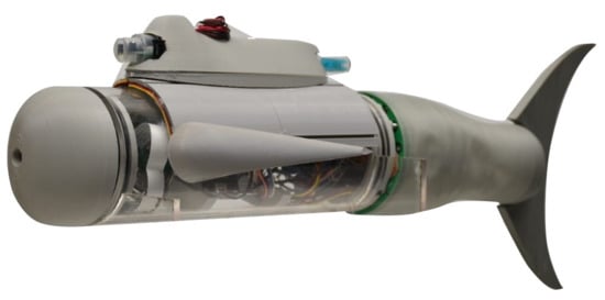
  • Nose: frontal part of the vehicle, which includes a camera to examine what is in front of the vehicle.
  • Body: contains the main electronic components, supports for electronic boards, the pectoral fins, and a structure for the dorsal fin that carries the sensors system.
  • Peduncle: consists of the biomimetic propulsion system carrying the caudal fin.

2.3. Prototyping

The prototype was manufactured and assembled with the following components:
  • Energy Source: Li-Polymer battery of 5000 mAh.
  • Onboard computer: A card size Raspberry 3B+ was selected due to the versatility in communications, programming, and greater ease of connection to other types of plug and play devices.
  • Actuators: For the propulsion system, there were three linear motion Actuonix L16-50-35-12-Ps with feedback of the position; they worked with an input voltage up to 15 VDC. The steering/tilting movements were achieved through the control of servomotors HS-5086WP for the pectoral fins.
  • Sensors and signal acquisition: The sensors of the BAUV depend on the activities to be carried out. For this research, the BAUV was equipped with:
    Inertial measurement unit: Integrates an accelerometer, gyroscope, and magnetometer. The BNO055 is a system in package (SiP), integrating the previously mentioned devices.
    Humidity sensor: Relative humidity is the ratio of the partial pressure of water vapor to the equilibrium vapor pressure of water at a given temperature. The AM2320 sensor provides measurements of temperature and relative humidity. This sensor aims to detect water leaks in the area of the circuits to take appropriate measures and avoid damage to the vehicle.
    PH meter: SEN0161 is an analog pH sensor with a voltage regulator and a filter at the output.
    Turbidity sensor: the TDS-10 module measures the number of suspended particles in water.
    Current sensor: This is used to determine the time of operation for a limited power source. A sensor AllegroTM ACS712 provides a way to sense the current for AC or DC circuits.
    Camera: Raspberry Pi 7757731, with 5 MP resolution.
  • Signal converters: ADS1115 is a precision ADC with 16 bits of resolution and 4 channels.
  • Drivers: A driver controls the operation of different devices from a control signal provided by the main CPU. This device can handle different scales of current according to the requirement of the actuator.
  • Communications: The type of communication used varies according to the development phase of the vehicle. First, for the testing phase, communication through WiFi and a serial interface was used for dry and water tests, respectively. The communication interfaces define the communication protocol, either TCP/IP for WiFi or asynchronous communication for serial. Later, more autonomous communications will be implemented, such as those mentioned by González et al. in [5]. Another type of communication in the vehicle was between the main CPU and the components; here, an I2C interface was implemented.
  • Printed circuit boards: To integrate the different actuators and sensors, a circuit board was designed to provide connectivity and power distribution. The schematic of Figure 4 shows the interconnection between boards.
An essential part of the novel design is the flexible peduncle required to cover the parallel mechanism and hold the caudal fin; this material represents the part of the flexible peduncle. The material proposed is polydimethyl-siloxane (PDMS) silicone Sylgard 184, which is durable, tensile, and resistant against water and most solvents [20]. All other parts of the parallel mechanism, as well as the dorsal and pectoral fins and the nose, were printed on polylactic acid filament (PLA). The caudal fin was made of flexible filament thermoplastic polyurethane (TPU). Figure 5 shows the final prototype and the respective components of it.

2.3.1. Instrumentation

The electrical system provides energy from the vehicle’s battery to the propulsion system, the sensors, the control system, and other actuators. A diagram of the hardware architecture is shown in Figure 6.

2.3.2. Software

The software was developed using Python language, given that the mainboard is Raspberry Pi 3B+. Python is an open-source programming language of a high-level. This language is defined as multi-paradigm; this means it is suited to different programming styles. A server-client architecture (Figure 7) was selected, with the BAUV’s onboard computer acting as the server and a laptop computer (station) being the client. This architecture was used during the testing period, but in the future, it will change to allow the BAUV to be more autonomous. In the testing period, a computer was used to monitor the data from the different sensors that allow knowing the BAUV’s status. The communication between the BAUV and the computer was performed using WiFi and serial communication for some of the tests.
The software of the system included a script that ran in the Raspberry Pi as a server onboard the BAUV and another PC client. The main processing was done in the Raspberry Pi; the client allowed us to monitor and change the values of the main actuators.
A graphical user interface was implemented on the client; Figure 8 shows its initialization. This interface showed the values of the sensors in real-time, and also allowed us to change the values of the actuators. Later, this interface will change depending on the type of control and communications system that will be implemented in the BAUV. The measurements of most sensors, except those of pH and turbidity, were used for control tasks.

2.4. Propulsion System Modeling

Parallel mechanisms perform a specific kinematics configuration that has advantages over serial configuration, such as mechanical simplicity and high rigidity [15]. AUVs with a parallel mechanism on the propulsion system can change orientation along arbitrary space trajectories; propeller position is adjusted producing a vectored thruster and resulting in smaller working space [16]. This work proposes a parallel mechanism with spherical 3-DOF motion using a 3UCU-1S architecture adapted to control the motion of the propulsion system with a caudal fin. The mechanism is composed on one base attached to the middle body, a moving platform carrying the caudal fin, three actuated limbs consisting of universal–cylindrical–universal joints from the base to the moving platform, and one passive limb fixed to the base and attached to the moving platform through a spherical joint. The cylindrical joint is formed by a rotational joint that has collinear axes with the prismatic joint of the servomotor; the underlined letter denotes the actuated joint [21].

2.4.1. Inverse Kinematics Analysis

The kinematics model is the mathematical representation of the position, velocity, and acceleration defined by the links and joints that conformed the robot with respect to the reference frame [1]. For this robot, a coordinate reference frame { A } was attached to the fixed base of the 3UCU-1S mechanism, and another coordinate frame { B } was attached to the moving platform. For convention, further analyses denote vectors and matrices as bold letters. The vector d i   ( i = 1 , 2 , 3 ) is from points A i to B i . For convenience, the origin of frame { B } was situated at the center of mass of the moving platform. The axes and frames were placed as shown in Figure 9.
The orientation of the moving platform is described by a rotation matrix ARB defined by roll, pitch, and yaw angles (   X Y Z Euler angle convention): that is, a rotation of Φ about the fixed x axis , a rotation of Θ about the fixed y axis , and a rotation of Ψ about the fixed z axis . Thus, the rotation matrix from the moving platform of frame { B } to the new global frame { A } is as follows:
A R B = [ C Θ C Φ S Ψ S Θ C Φ C Ψ S Φ C Ψ S Θ C Φ + S Ψ S Φ C Θ S Φ S Ψ S Θ S Φ + C Ψ C Φ C Ψ S Θ S Φ S Ψ C Φ S Θ S Ψ C Θ C Ψ C Θ ] .
The length of the limb l i and its unit vector s i are:
d i = l i s ^ i = P + A R B A b i a i ,
l i = d i = d i · d i ,
s ^ i = d i l i ,
then, the linear and angular velocity of the center of the ball joint v b i and ω i , linear and angular acceleration of the center of the ball joint v ˙ b i and ω ˙ i , and accelerations of the mass center of the cylinder and piston v ˙ 1 i and v ˙ 2 i are obtained from their corresponding derivatives. Considering that s ^ ˙ i = ω × s ^ i and, A R ˙ B = ω × A R B , then the closed kinematics are given by:
d ˙ i = v b i = ω × b i .
Universal joints of the linear actuators with the moving platform constrain the limbs to spin over the longitudinal axis, and therefore ω i · s ^ i = ω i ˙ · s ^ i = 0 and s ^ i × ( ω i × s ^ i ) = ω i . Then, the derivative of l i s ^ i gives the angular velocity:
ω i = 1 l i ( s ^ i × v b i ) .
For linear and angular acceleration, ( ω i × ( ω i × s ^ i ) ) · s ^ i = ω i · ω i is considered.
d ¨ i = v ˙ b i = ω ˙ × b i + ω × ( ω × b i ) ,
ω ˙ i = 1 l i ( s ^ i × v ˙ b i 2 l ˙ i ω i ) .
where b i is the distance from the center of the platform to the ball joint of the i t h limb and a i is the distance of the center of the base to the universal joint of the i t h limb. Each linear actuator is decomposed into two parts, as shown in the body diagram of Figure 10, with masses m 1 i and m 2 i . The position of each center of mass are r 1 i and r 2 i . Then, their corresponding linear velocities and accelerations are:
r 1 i = a i + c 1 i s ^ i ,
r 2 i = a i + ( l i c 2 i ) s ^ i ,
v 1 i = c 1 i ( ω i × s ^ i ) ,
v 2 i = l ˙ i s ^ i + ( l i c 2 i ) ( ω i × s ^ i ) ,
v ˙ 1 i = c 1 i ( ω ˙ i × s ^ i + ω i × ( ω i × s ^ i ) ) = c 1 i ( ω ˙ i × s ^ i ) + ω i × v 1 i ,
v ˙ 2 i = l ¨ i s ^ i + 2 l ˙ i ( ω i × s ^ i ) + ( l i c 2 i ) ( ω ˙ i × s ^ i ( ω i · ω i ) s ^ i ) .

2.4.2. Inverse Dynamics Analysis

While the kinematics of parallel manipulators have been extensively studied, just a few papers have analyzed the dynamics in these systems. The dynamical model can be used for the simulation of the robotic system and the implementation of control strategies. The dynamic analysis determines the reaction forces and moments due to the position and velocity of the robot. A dynamical model of parallel manipulators is complicated because of the multiple closed-loop chains [1,22].
The inverse dynamics formulate the system equation of motion (EOM) and execute the histories of the controlling actuated joint forces and moments [23]. This is important for generating high performance of control algorithms, while the forward dynamical model is used for simulation [24]. The principle of virtual work [25] δ W = 0 is a compact form of the EOM since it eliminates constraint forces and is considered at static equilibrium. Virtual displacements are small displacements that do not break any constraints and are non-time dependent.
Applied and inertia forces exerted at the center of mass of the moving platform F p , and applied and inertia forces exerted at the centers of mass of the cylinder F i 1 and piston F i 2 , are defined with the simplified equations proposed by [26].
F k = [ f e + m k g + m k v ˙ k n e I k ω ˙ k ω k × ( I k ω k ) ] ,
where I k and m k are the inertia matrix and mass of the moving platform, cylinder, and piston, respectively.
To solve the dynamical EOM for the actuator forces τ , the external forces applied to the moving platform are supported by the force acting on the passive limb, assuming there are no external forces applied to the passive limb, only actuator forces; therefore, the passive force does not contribute in the moments applied to the moving platform’s center of mass.
τ = J p T ( F p + i j J i j T F i j ) .
The Jacobian matrix J p T describes the relation of angular and linear velocities of the moving platform with the joints, while J i j is the Jacobian matrix of the j t h body’s (for the cylinder and piston) i t h limb, being X = [ p x p y p z Φ Θ Ψ ] and L = [ d 1 d 2 d 3 ] :
L ˙ = J p X ˙ X ˙ i j = J i j X ˙ p .

2.4.3. Forward Dynamics Analysis

In forward dynamics, the actuator forces and external disturbance wrench applied to the manipulator are known, and the trajectory of the platform is calculated. The explicit dynamic equation is:
J p T   τ a = M T X ¨ + C T X ˙ + G T τ d ,
for τ a is the vector of actuator forces and τ d is disturbance forces. M T , C T , and G T correspond to the inertia matrix, Coriolis and centrifugal forces matrix, and gravity vector defined by [26]:
M T = M p + i j J i j T M i j J i j ,
C T = C p + i j J i j T C i j J i j + J i j T M i j J ˙ i j ,
M T = G p + i j J i j T G i j ;
Each matrix has the following structure:
M k = [ m k 1 3 x 3 0 3 x 3 0 3 x 3 I k ] ,
C T = [ 0 3 x 3 0 3 x 3 0 3 x 3 ( ω k ) × I k ] ,
G T = [ m k g 0 3 x 1 ] ,
where ( ω k ) × is the skew-symmetric matrix of the angular velocity of the k t h element, and the Jacobian time derivative matrices are defined as:
x ¨ i j = J ˙ i j X ˙ p + J i j X ¨ p .

3. Simulations and Experiments

The analysis of the mechanism simulated on Solidworks® is divided into three types of motion; Figure 11 shows first the caudal fin in the vertical position, then the caudal fin is turned 90° to hold a horizontal position.
The simulation followed the parameters listed in Table 2. Each experiment shows the displacement graph of the three limbs and the projection angle of the platform corresponding to the case of movement.
  • Experiment 1: The caudal fin starts in a neutral position for a vertical fluttering to swim like a tuna. Then, the caudal fin starts to flap from −30° to +30° for a total caudal amplitude of 60° (Figure 12).
  • Experiment 2: The caudal fin starts in a neutral position for a vertical fluttering and then turns 90° along the body axis, positioning it for a horizontal fluttering to swim like a dolphin. Then, the caudal fin starts to flap from −30° to +30° for a total caudal amplitude of 60° (Figure 13).
To verify the correctness of the forward dynamics model, a closed-loop proportional-derivative (PD) controller was implemented, as shown in the block diagram of Figure 14. It had the desired trajectory for the motion of the moving platform in three distinct scenarios: for a motion of 30° in roll only, then 30° in pitch only, and finally 30° in yaw only; the results are shown in Figure 15. The trajectory of the moving platform X ( t ) was measured and compared to the desired trajectory X d ( t ) . Furthermore, the tracking error e ( t ) = X d ( t ) X ( t ) was fed to a controller to determine the required wrench needed. The platform orientation is described by the roll–pitch–yaw angles ( Φ Θ Ψ ) trying to reach the desired trajectory ( Φ d Θ d Ψ d ).
The gravity compensation block was applied to attenuate the effect of gravity on the tracking performance, then a gravity compensation term was added to this wrench. This term is indeed the term G ( x ) of Equation (24), derived from the dynamic formulation. The desired and real closed-loop motions were similar. The PD controller with gravity compensation was able to reduce tracking errors. Note that the controller used in this simulation was in its simplest form. However, the gravity compensation feedback is the key point to reach such a performance with a simple PD structure in control [25]. For this simulation, no disturbances of the hydrodynamical lateral forces were added.

4. Conclusions and Future Work

In this work, a novel BAUV design that employs a parallel mechanism to manipulate the position of a caudal fin was developed. The proposed propulsion system allows for the use of different types of swimming, e.g., vertical like a tuna and horizontal like a dolphin. Moreover, it is possible to use intermediate orientations of the fin and have a thrusted vector. These features will increase the maneuverability of the vehicle.
The architecture of the vehicle was designed considering the necessary systems to implement in the near future for a fully autonomous vehicle. The main components included an onboard computer, sensors, actuators, and power and communication protocols. In addition, to perform the testing of the subsystems, a simple graphical interface was designed.
A motion analysis study was performed in order to know the sequence of movements and extensions of the limbs to follow a flapping motion previously established, simulating a vertical fluttering with a caudal amplitude of 30°, then turning to a horizontal position of the caudal fin and repeating the same fluttering at the new position. These results provide design information for future research on advanced control strategies for the planning trajectory of the BAUV to increment the efficiency and autonomy of the vehicle.
The PD controller implemented for simulation showed good performance for the direct dynamics model; however, it worked correctly with no disturbance forces, so more advanced controllers will be implemented to deal with the hydrodynamical lateral forces applied to the caudal fin.
Future work will also include underwater dynamics simulations, advanced control strategies for the desired path planning, as well as physical tests with the prototype. To give more autonomy to the vehicle, a reliable communication system needs to be designed and implemented. The graphical user interface will be evolving along with the improvements and implementation of the prototype.

Author Contributions

Conceptualization, C.T.A.-G., E.A.N.D., and L.E.G.-C.; methodology, C.T.A.-G. and L.E.G.-C.; software, C.T.A.-G. and E.A.N.D.; validation, A.V.-M., J.I.M.-L., and L.I.M.-Á.; formal analysis, C.T.A.-G. and L.E.G.-C.; investigation, A.V.-M., J.I.M.-L., and L.I.M.-Á.; resources, L.E.G.-C.; data curation, C.T.A.-G. and E.A.N.D.; writing—original draft preparation, C.T.A.-G. and L.E.G.-C.; writing—review and editing, A.V.-M., J.I.M.-L., and L.I.M.-Á.; visualization, C.T.A.-G. and E.A.N.D.; supervision, L.E.G.-C.; project administration, L.E.G.-C.; funding acquisition, L.E.G.-C. All authors have read and agreed to the published version of the manuscript.

Funding

This research was funded partially by Tecnologico de Monterrey and Aixware Technologies, Monterrey, NL, México.

Conflicts of Interest

The authors declare no conflicts of interest.

References

  1. Sahoo, A.; Dwivedy, S.K.; Robi, P.S. Advancements in the field of autonomous underwater vehicle. Ocean Eng. 2019, 181, 145–160. [Google Scholar] [CrossRef]
  2. Shukla, A.; Karki, H. Application of robotics in offshore oil and gas industry—A review Part II. Robot. Auton. Syst. 2016, 75, 508–524. [Google Scholar] [CrossRef]
  3. Moreno, H.A.; Saltarén, R.; Puglisi, L.; Carrera, I.; Cárdenas, P.; Álvarez, C. Robótica submarina: Conceptos, elementos, modelado y control. RIAI-Rev. Iberoam. Automática e Inf. Ind. 2014, 11, 3–19. [Google Scholar] [CrossRef] [Green Version]
  4. Alam, K.; Ray, T.; Anavatti, S.G. A brief taxonomy of autonomous underwater vehicle design literature. Ocean Eng. 2014, 88, 627–630. [Google Scholar] [CrossRef]
  5. González-García, J.; Gómez-Espinosa, A.; Cuan-Urquizo, E.; García-Valdovinos, L.G.; Salgado-Jiménez, T.; Cabello, J.A.E. Autonomous Underwater Vehicles: Localization, Navigation, and Communication for Collaborative Missions. Appl. Sci. 2020, 10, 1256. [Google Scholar] [CrossRef] [Green Version]
  6. Kruusmaa, M.; Fiorini, P.; Megill, W.; de Vittorio, M.; Akanyeti, O.; Visentin, F.; Chambers, L.; El Daou, H.; Fiazza, M.C.; Ježov, J.; et al. FILOSE for Svenning: A Flow Sensing Bioinspired Robot. IEEE Robot. Autom. Mag. 2014, 21, 51–62. [Google Scholar] [CrossRef]
  7. Chowdhury, A.R.; Panda, S.K. Brain-map based carangiform swimming behaviour modeling and control in a robotic fish underwater vehicle. Int. J. Adv. Robot. Syst. 2015, 12, 52. [Google Scholar] [CrossRef] [Green Version]
  8. Sfakiotakis, M.; Lane, D.M.; Davies, J.B.C. Review of fish swimming modes for aquatic locomotion. IEEE J. Ocean. Eng. 1999, 24, 237–252. [Google Scholar] [CrossRef] [Green Version]
  9. Zhou, K.; Liu, J.; Chen, W. Numerical Study on Hydrodynamic Performance of Bionic Caudal Fin. Appl. Sci. 2016, 6, 15. [Google Scholar] [CrossRef]
  10. Shriyam, S.; Agrawal, A.; Behera, L.; Saxena, A. Robotic Fish Design and Control Based on Biomechanics. In Proceedings of the Third International Conference on Advances in Control and Optimization of Dynamical Systems, Kanpur, India, 13–15 March 2014; Volume 47. [Google Scholar]
  11. Chowdhury, A.R.; Prasad, B.; Vishwanathan, V.; Kumar, R.; Panda, S.K. Bio-Harmonized Dynamic Model of a Biology Inspired Carangiform Robotic Fish Underwater Vehicle. IFAC Proc. Vol. 2014, 47, 7258–7265. [Google Scholar] [CrossRef] [Green Version]
  12. Hu, Y.; Zhang, S.; Liang, J.; Wang, T. Development and CPG-Based Control of a Biomimetic Robotic Fish with Advanced Underwater Mobility. In Proceedings of the IEEE International Conference on Robotics and Automation (ICRA), Hong Kong, China, 31 May–7 June 2014; pp. 813–818. [Google Scholar]
  13. Katzschmann, R.K.; DelPreto, J.; MacCurdy, R.; Rus, D. Exploration of underwater life with an acoustically controlled soft robotic fish. Sci. Robot. 2018, 3, eaar3449. [Google Scholar] [CrossRef] [Green Version]
  14. Cavallo, E.; Michelini, R.C.; Filaretov, V.F. Conceptual design of an AUV equipped with a three degrees of freedom vectored thruster. J. Intell. Robot. Syst. Theory Appl. 2004, 39, 365–391. [Google Scholar] [CrossRef]
  15. Pazmiño, R.S.; Cena, C.E.G.; Arocha, C.A.; Santonja, R.A. Experiences and results from designing and developing a 6 DoF underwater parallel robot. Robot. Auton. Syst. 2011, 59, 101–112. [Google Scholar] [CrossRef]
  16. Wang, R.; Guo, X.; Zhong, S. An underwater vector propulsion device based on the RS+2PRS parallel mechanism and its attitude control algorithm. Appl. Sci. 2019, 9, 5210. [Google Scholar] [CrossRef] [Green Version]
  17. Raj, A.; Thakur, A. Fish-inspired robots: Design, sensing, actuation, and autonomy—A review of research. Bioinspir. Biomim. 2016, 11, 031001. [Google Scholar] [CrossRef] [PubMed]
  18. Yu, J.Z.; Wen, L.; Ren, Z.Y. A survey on fabrication, control, and hydrodynamic function of biomimetic robotic fish. Sci. China Technol. Sci. 2017, 60, 1365–1380. [Google Scholar] [CrossRef]
  19. Fossen, T.I. Handbook of Marine Craft Hydrodynamics and Motion Control, 1st ed.; John Wiley & Sons Ltd.: Trondheim, Norway, 2011. [Google Scholar]
  20. Masoomi, S.F.; Haunholter, A.; Merz, D.; Gutschmidt, S.; Chen, X.; Sellier, M. Design, fabrication, and swimming performance of a free-swimming tuna-mimetic robot. J. Robot. 2014, 1–7. [Google Scholar] [CrossRef] [Green Version]
  21. Leal Merlo, S.A. Design, Construction and Control of the 3-UCU, 1-S Parallel Mechanism with Spherical Motion for Forearm and Wrist Prosthetics; Instituto Tecnológico y de Estudios Superiores de Monterrey: Monterrey, NL, Mexico, 2014. [Google Scholar]
  22. Tsai, L.-W. Solving the Inverse Dynamics of a Stewart-Gough Manipulator by the Principle of VirtualWork. J. Mech. Des. 2000, 122, 3–9. [Google Scholar] [CrossRef]
  23. Khan, W.A.; Krovi, V.N.; Saha, S.K.; Angeles, J. Modular and recursive kinematics and dynamics for parallel manipulators. J. Dyn. Syst. Meas. Control 2005, 127, 529. [Google Scholar] [CrossRef]
  24. Khalil, W.; Guegan, S. A Novel Solution for the Dynamic Modeling of Gough-Stewart Manipulators. In Proceedings of the 2002 IEEE International Conference on Robotics and Automation (Cat. No.02CH37292), Washington, DC, USA, 11–15 May 2002; Volume 1, pp. 817–822. [Google Scholar]
  25. Taghirad, H.D. Parallel Robots Mechanics and Control; CRC Press: Boca Raton, FL, USA, 2013. [Google Scholar]
  26. Lemus, D.; Rodriguez, C.F.; Yime, E. Inverse Dynamic Explicit Formulation of a Stewart—Gough Manipulator Based on the Virtual Work Approach. In Proceedings of the 7th European Nonlinear Dynamics Conference (ENOC 2011), Rome, Italy, 24–29 July 2011. [Google Scholar]
Figure 1. Fins and movements performed by a fish.
Applsci 10 02426 g001
Figure 2. Caudal fin design in Autodesk® Fusion 360™.
Applsci 10 02426 g002
Figure 3. Biomimetic autonomous underwater vehicle (BAUV) computer-aided design (CAD) developed by Autodesk® Fusion 360™. 1, nose; 2, body; and 3, propulsion.
Applsci 10 02426 g003
Figure 4. Schematic design of electronic systems in the BAUV. Vcc, V1, and V2 are voltage signals; SDA are serial data; SCL are serial clock signals; and Analog refers to analog signals.
Applsci 10 02426 g004
Figure 5. The prototype developed and its components.
Applsci 10 02426 g005
Figure 6. Architecture diagram of the BAUV hardware.
Applsci 10 02426 g006
Figure 7. Architecture diagram of the BAUV software.
Applsci 10 02426 g007
Figure 8. Graphical interface on the client script.
Applsci 10 02426 g008
Figure 9. Closed-loop kinematics for the 3 universal–cylindrical–universal and 1 spherical joint (3UCU-1S) mechanism.
Applsci 10 02426 g009
Figure 10. Free body diagram of the (a) platform, (b) limbs, and (c) center of mass of the cylinder and piston.
Applsci 10 02426 g010
Figure 11. Simulation of the caudal fin (a) in a vertical position and (b) horizontal position.
Applsci 10 02426 g011
Figure 12. Motion study for Experiment 1: (a) neutral position, (b) fin position vertical at −30°, (c) limbs displacement at −30°, (d) fin position vertical at +30°, and (e) limbs displacement at +30°.
Applsci 10 02426 g012
Figure 13. Motion study for Experiment 2: (a) neutral vertical position, (b) fin position is horizontal, (c) limbs displacement for a 90° turn, (d) fin position is horizontal at −30°, (e) limbs displacement at −30°, (f) fin position is horizontal at +30°, and (g) limbs displacement at +30°.
Applsci 10 02426 g013
Figure 14. Block diagram of the forward dynamic in a closed-loop.
Applsci 10 02426 g014
Figure 15. The desired and output trajectories in a closed-loop for a platform orientation of 30° at (a) roll ( Φ ), (b) pitch ( Θ ), and (c) yaw ( Ψ ) angles.
Applsci 10 02426 g015
Table 1. The Society of Naval Architects and Marine Engineers (SNAME) notation for DOF and forces acting on a submersible body.
AxisMotionSNAMEPositionVelocityForce
xtranslationsurgexuX
ytranslationswayyvY
ztranslationheavezwZ
xrotationrollϕpK
yrotationpitchθqM
zrotationyawψrN
Table 2. Structure parameters for motion simulation.
ParameterSymbolValueUnit
Static arm longitude p z 178mm
Distance from { B } to B i a47mm
Distance from { A } to A i b25mm
Euler angles for motionα,
β,
γ
−30 to +30,
0,
0 to +90
deg
B i distributionψi0, 120, 240deg
A i distributionχi0, 90, 270deg

