1. Introduction
Recently, with the progress of Internet of things technology, smart home, intelligent driving, unmanned monitoring and other terminal and network fusion technology is changing our lives. It is hoped that the functions that can be implemented by terminals will become more and more complex, which means that limited capacity and capability terminals will be unable to solve computation-intensive and latency-critical tasks.
Mobile edge computing (MEC) network is a new type of network architecture technology [
1]. The MEC server with powerful computing storage capabilities is close to the edge of the network and can effectively reduce the energy consumption and delay caused by the data transmission distance and bandwidth limitations [
2,
3]. In environments far from cities (such as emergency rescue, crop condition monitoring, and power line inspection) [
4], practical problems occur, including rapid networking, low-cost network coverage, and short-term business requirements. In emergency rescue, when the unfavorable environment causes the ground communication network to be unavailable or unreliable, rapid networking is needed to ensure timely communication of detection and rescue information collected by terminal equipment [
5]. The amount of data from monitoring points in agricultural areas is large, and the monitoring points are far away from wireless access points and edge cloud facilities. Monitoring points need to analyze and process crop information for a period of time to get the next stage of cultivation direction. The monitoring points have limited storage and computing capacity and need to establish temporary communication with the edge cloud [
6]. The inspection environment of electric power lines is similar to that of agriculture. The location of power lines is remote, and the inspection lines are not fixed, so flexible communication networks are also needed. Evidently, the construction of a fixed MEC service site requires a certain construction period, and the investment cost is extremely low. As a new type of increasingly mature equipment, an unmanned aerial vehicle (UAV) is characterized by its deployment and flexibility [
7,
8]. Combined with the MEC network and the UAV which performs MEC server functions in complex environments, the MEC can realize the rapid deployment and flexible offloading of computing tasks [
9,
10,
11], with a broad application prospect.
The UAV mainly performs two functions in the process of MEC network fusion. One function is to monitor and measure as a terminal device. When the UAV’s own data processing ability is weak, offloading its own task to the surrounding MEC server is necessary for calculation [
12,
13]. Another function of the UAV is to act as a MEC server by using computing resources on the UAV to process computing tasks sent from the terminal equipment in a timely manner. Route planning is required when the UAV is serving in a highly mobile region. The UAV is a dynamic MEC node, whereas the access point (AP) is a static counterpart, and both provide joint computing services. Asheralieva et al. [
14] proposed a second-order random hierarchical game ground MEC (G-MEC) operation mode to coordinate the resources between the UAV and AP and serve users effectively. Hu, Q. et al. [
15] involved a UAV-assisted edge computing system in which the UAV serves as the ground terminal. The UAV trajectory, offloading task ratio, and user scheduling variables are jointly optimized with the maximum delay and minimum as objectives. The UAV in [
16] is used to assist nodes for computing-intensive task execution by providing air and ground offloading and realizing resource scheduling between the terminal and the MEC server. The model has the characteristics of energy perception and delay perception. In [
17], considering UAVs with microwave power transfer (MPT), an on-board deep Q-network is developed to minimize the overall data packet loss of the sensing devices by optimizing the device charging and interrogating for data collection and the instantaneous patrol velocity of the UAV through a Markov decision process (MDP). The MDP algorithm can be regarded as an extension of the Lyapunov optimization algorithm, has an excellent performance in solving optimal decision problems, and is also widely used in solving machine learning optimization algorithms.
The above two kinds of UAV functions have some limitations. The first kind of UAV as a terminal only undertakes the data acquisition function. Given its own hardware constraints, the UAV can neither process nor store (promptly and for an extended time) numerous video and sensor data. Such a UAV is a burden on the network, can only collect data flexibly, and fails to realize flexible network connectivity. Another kind of UAV functions as a server or auxiliary server in the MEC network to enable computation and provide storage for the terminal, but the limitation of the UAV itself cannot be ignored. Limited energy, computing resources, and substantial hovering mechanical energy consumption render the UAV unable to handle large data processing or can only assume the auxiliary computing function. Accordingly, the edge network still has limitations and is unable to deploy the network flexibly and quickly. The problem of the power supply is always the key to solving issues when the UAV acts as the MEC server. Given that the UAV’s own energy is insufficient, its MEC function must be weakened to allow the UAV to relay data.
The UAV acts as a relay to assist information transmission in wireless networks and generates new ideas for the integration of UAV and MEC networks. On the basis of considering propagation loss, shadow, and multipath fading, a UAV-based multi-hop relay channel model is established in [
18]. In addition, the cascade propagation loss and cascade probability density function of the channel fading of the relay link are derived. Considering the limited energy characteristics of the UAV, UAV, Ji, B. et al. [
19] studied the energy collection problem of multiple UAV relay networks in the Internet of things system to overcome the large-scale fading between the source and receiver, thereby realizing green collaborative communication. In [
20], a framework for MEC-enabled cognitive radio (CR) networks is proposed, which integrates three technologies: MEC, CR, and wireless power transfer (WPT), in which the UAV performs collaborative relay during communication. WPT technology can use solar or wind energy to charge the UAV and provide a controllable and stable energy supply, which can significantly improve the performance of access to the MEC network. This study considers WPT technology to realize UAV green energy charging. On the one hand, with the UAV as the relay node, the energy consumption and the task burden of the UAV is limited, and the network coverage and the long-distance communication ability are increased. On the other hand, the task is transmitted to the remote MEC server through the relay, and the task runs on the resource-rich fixed server, thereby reducing the task processing delay and energy consumption. However, considering the increase of one-hop forwarding, the network reliability of the edge network, including relay, may be reduced. In addition, the bit–error rate (BER) and interrupt probability problems cannot be ignored, and the transmission distance of the relay communication is relatively large. Such factors will cause a certain transmission delay. How to balance the demand for reliability and delay is an important research direction. In addition, how the UAV relay function and the MEC service function of the UAV are used in coordination to improve the overall system performance is also of practical significance.
In the current strategy, the case where the UAV simultaneously performs data relaying and edge computing may be considered, and this approach enhances the function of the UAV in the MEC fusion network. Such a flexible network layout can maximize the advantages of the fusion network, which can not only undertake considerable data processing but also increase the network reliability. Zhang, T. et al. [
21] aimed at minimum energy consumption and studied the edge offloading of UAV-assisted relaying and computation by applying the iterative algorithm through the Lagrangian duality method and successive convex approximation (SCA) technique. Hu, X. et al. [
22] studied the architecture of a UAV-assisted MEC. During multiple constraints where the UAV simultaneously relayed data and computing tasks, the study used alternating iterations to identify the optimal computational resource scheduling, bandwidth allocation, and UAV trajectory with the minimum weighted energy consumption as the goal. In the above study, the UAV performs relay and computing tasks in the same time slot, but the two functions are not really distinguished among different sizes of tasks. Moreover, the burden of both functions on the already energy-limited UAV load and consumption is remarkably large, and an extremely complex task undertaken by the UAV will greatly reduce the UAV working time. Furthermore, the delay limitation problem is not considered. Unlike [
21] and [
22], the present study perceives that the UAV assumes only one function of relay or MEC when the task is offloaded, and this method establishes a multilevel edge network resource optimization model (MENROM) to optimize the function selection of the UAV in the MEC network. The above resource allocation algorithm does not consider the current actual energy state of the UAV.
Green energy (e.g., solar energy) will provide the UAV with a longer and stronger battery life in the network. The cost of the UAV processing task will be affected by its own energy surplus factors and will then affect the overall network utility. In heterogeneous networks, low-cost networks (e.g., Wi-Fi networks) can reduce transmission costs and cause the task offloading process to take full advantage of resources [
23]. In view of the energy and network situation and considering the UAV relay function, this study proposes a MENROM based on the MDP algorithm. In summary, the main contributions of this work are presented as follows:
A multilevel offloading network structure model with terminal devices, UAV, and remote G-MEC server is constructed for scenarios with long-range and low-cost coverage, such as emergency communication, in which the UAV with a green energy charging function assumes two functions: the relay node and MEC server.
The UAV energy case is divided into four energy levels to determine its energy status. Considering the current energy level state of the UAV, this study proposes an optimal resource allocation and task offloading strategy according to the energy level and comprehensive performance evaluation. The model selects optimal resource allocation and makes task offloading decisions on the basis of UAV energy levels and system resources. The MDP is applied to solve the model’s offloading problem. In addition the optimal resource optimization and offloading decision are obtained using the iterative method.
Considering the network performance evaluation, BER in the network and interrupt probability, the reliability indexes is set. The reliability indexes indicates the probability of successfully offloading the computing task to the computing node to complete the calculation and return of the result. The normalized delay, energy consumption, and other parameters increase the reliability of the system. According to the above setting, this study conducts a simulation analysis of the network and realizes multilevel edge network resource optimization and the intelligent offloading decision.
2. Multilevel Edge Network Task Offloading Model
This study focuses on emergency communication in disaster areas, agricultural data collection in remote residential areas, power network monitoring, and other scenarios where terminals are far away from network servers and cannot directly obtain computing services. This work proposes a multilevel edge network task offloading strategy on the basis of the MDP algorithm. When the terminal has actual computing requirements, the UAV, which undertakes two functions of MEC server computing or relay forwarding, follows a fixed algorithm to approach the terminal and hover flights with position adjustment [
16]. The UAV will choose specific functions according to its own energy status and task size. That is, the UAV will determine whether the task is executed on the UAV as a MEC server or on a remote ground-fixed MEC server with a UAV relay.
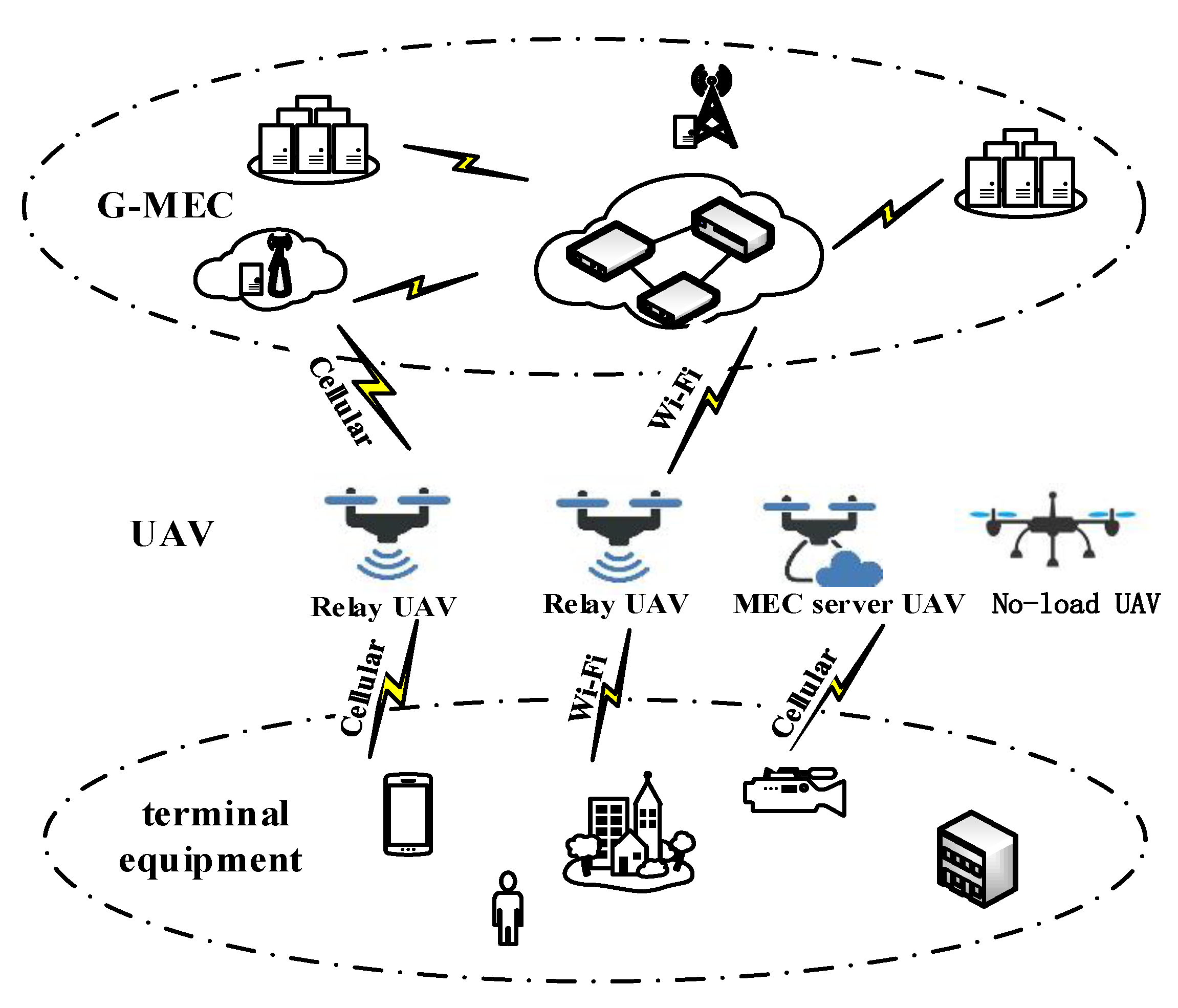
Figure 1 shows the task offloading model.
As shown in
Figure 1, this study constructs a three-level network offloading model, including the terminal equipment, the UAV layer, and the distal G-MEC layer. The UAV can consider offloading the task to terminals, the UAV, or the G-MEC according to the actual situation, such as the task size and UAV energy level. The UAV acts as a relay node for the offloading of the task by the G-MEC and connects the terminal device to the remote G-MEC.
This study considers a multilevel offloading model of UAV relay to achieve rapid deployment, reduce the deployment cost, extend the network service range, and facilitate improved flexibility of the edge computing network layout. The UAV can provide the edge cloud service for many regions and realize the efficient utilization of network resources. During resource optimization, the UAV WPT technology, which is considered in the model to realize solar energy charging and solve its own energy level problems, ensures the reliability and Quality of Service (QOS)of the system and increases the working hours and system stability of the UAV.
2.1. Multilevel Network Structure
This study considers an edge cloud containing heterogeneous networks with different wireless access technologies (e.g., Wi-Fi and cellular networks) deployed in the network.
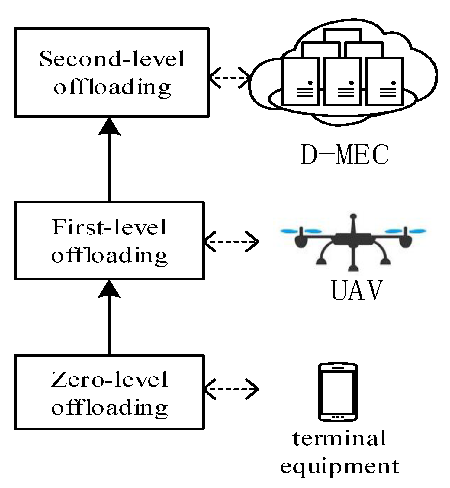
The proposed system includes a three-level offloading model of the user, UAV, and G-MEC levels, as shown in
Figure 2. The user level includes the monitoring equipment, mobile users, and other terminal equipment. The UAV level contains the UAV with the MEC server and relay functions. The UAV has certain computing resources and the relay ability to transfer the computing task to the G-MEC level. The G-MEC level contains a ground-fixed MEC server close to the user. Moreover, the G-MEC has substantial computing resources and energy, which can provide a powerful computing offloading service.
Zero-level offloading (Level 0): If the user’s available resources can process the computation task within the required QOS wait time, then the user performs local processing. Zero-level offloading applies to tasks that require simple low computing and energy resources.
First-level offloading (Level 1): The terminal device unloads the task to the nearby UAV, which acts as the MEC server for computing task processing. The first-level offloading is applicable to the local resources that cannot undertake the computation task completion, and the user offloads the problem task to a suitable nearby UAV with the MEC server function.
Second-level offloading (Level 2): After the terminal device offloads the task to the UAV, the UAV serves as a relay to re-forward the task to a resource-sufficient G-MEC server. The secondary offloading is applicable when the problem task is so complex that neither the mobile terminal nor the UAV can undertake the processing of the computing task. Alternately, when the UAV energy is insufficient, the UAV acts as a relay node to offload the problem task to the G-MEC. The G-MEC processes the task and returns the result.
If the task cannot be offloaded to any edge server and cannot be computed locally, then the task will be delayed.
Processing computing tasks at different offloading levels generates different transport and energy costs. As the G-MEC is generally located far from the mobile device and requires relay transmission, the high transmission delay and transmission energy consumption of the computation offloaded to the G-MEC may lead to higher transmission costs. The reliability of the system may be reduced by increasing the BER and interrupt probability due to the relay and distance. However, the task offloaded to the G-MEC has a low computational cost, sufficient computing and energy resources, low computational delay, and the capability to undertake complex tasks. When the computing task is offloaded in the UAV, the delay and transmission costs are small, and the reliability is high because of the close transmission distance. However, given the limited energy of the UAV, the cost of running and calculating the energy consumption is high, and its own energy resource condition affects the reliability of task completion. Transport costs are not required to handle tasks in mobile devices, but local computing delays and energy costs cannot be supported because of hardware constraints.
The equipment at each terminal deploys a decision engine to implement the offload selection algorithm proposed in this study. The required decision engine determines whether the current task can be performed locally or whether it needs to be unloaded to the appropriate offloading level. Considering the heterogeneous network and UAV mobility and energy finiteness problems, this study chooses to optimize with MDP to obtain the best resource optimization scheme.
2.2. Offloading Node Resources
In the multilevel edge network constructed in this study, the utility functions of the terminal, the UAV, and the G-MEC sides relayed by the UAV are calculated. The UAV can be charged by solar panels, so the UAV energy storage situation can be divided into the high energy level of charging completion and the low energy level of unfilled energy. Moreover, the UAV utility function is related to its energy level. The comprehensive utility function identifies the optimal resource optimization strategy using the MDP algorithm, thereby ensuring system reliability and QOS.
The utility function is divided into three offloading modes: local, UAV, and G-MEC offloading. That is, the task performs computation on the terminal device side, the task offloads to the UAV side, which acts as the MEC server, and the task offloads through the UAV relay to the distal G-MEC side for computation. The task has a random size of Z bit, and running 1 bit requires k CPU (Central Processing Unit) cycles. The total number of CPU cycles, Nz, is required to process the Z bit task. f(a) is the reward function for the task to complete the calculation within the maximum task processing time and the equipment within the minimum equipment remaining charge. The decision action set is A, which includes Ou, OA, and OM, where OA and OM indicate that the terminal equipment offloads the task to the UAV and G-MEC. Meanwhile, Ou denotes the action in which the task is processed at the mobile device. A can be described by A = {Ou,OA,OM}. Rou, Rouav, and RoGMEC are reward values for corresponding terminal computation, UAV offloading, and G-MEC offloading, respectively.
2.2.1. Terminal Computation
When the task data is small and the terminal computing and energy resources can undertake the task processing, the task performs the calculation locally, consumes local energy and computing resources, and causes an operation delay. Local energy consumption (
Eu) and running delay (
Tu) are given as follows:
where
δu represents the energy consumed by the task to perform 1 cycle with the local terminal equipment, and Ru represents the terminal equipment operation rate. When the operation delay of the task is less than the delay deadline (
Tdeadline) and the remaining energy (
Eu-r) of the equipment is greater than the energy deadline (
Edeadline), the system can obtain the reward value expressed as follows:
where
Eu-c denotes the initial power of the terminal equipment prior to task processing. When the delay and energy deadline are not satisfied, the system will not obtain the reward function.
2.2.2. UAV Offloading
When the terminal equipment cannot support task computing, the terminal equipment can offload the task to the edge computing server. The UAV in this model can be used as a MEC server or as a relay node to relay the task data to the G-MEC for calculation. This section discusses the UAV serving as a MEC server to provide computing offloading services for terminal equipment. The UAV offloading utility function is also divided into the delay and energy parts.
The delay partial utility function considers the transmission (
Tuav-c), propagation (
Tuav-b), and computational (
Tuavx) delays as follows:
where
Ruav-b is the transmission speed,
B is the channel bandwidth,
h0 is the channel gain, and
σ is the noise power.
q is the path decay index. Meanwhile,
du denotes the transfer distance from the terminal to the UAV,
Pu denotes the terminal transmit power, and
Ruav denotes the task running rate on the UAV. Additionally,
v is the propagation rate (approximately the speed of light). Total delay function (
Tuav-z) is obtained by combining the transmission, propagation, and computational delays as follows:
The return result data are small, and the data return time is ignored here. The energy utility function considers the energy consumed by the UAV calculation (
Euav), by the UAV operation (
Euav-w), and by the signal emitted by the terminal (
Euav-u). Thus,
Euav,
Euav-w, and
Euav-u are given by as follows:
where
δuav is the energy consumed by the task of performing a cycle at the UAV and
Puav-w is the UAV operating mechanical power.
Green energy charging, such as solar panels, can increase the working time of the UAV, enhance the reliability of UAV processing tasks, provide more unloading services for terminal devices, and make the offloading system more flexible and easy to implement. This model considers using WPT technology to recharge the UAV with solar or wind energy. The tasks are assumed to be independent of one another, and the energy is in a dynamic process. The model differentiates the energy stored in the UAV from high to low into four levels,
Elevel = {1, 2, 3, 4}. Energy level 4 is the state of abundant electricity between 100% and 75%. Energy level 3 is the power of the UAV after a period of operation, with electricity between 75% and 50%. Energy level 2 is the amount of electricity that the UAV runs for an extended time between 50% and 25%. Finally, energy level 1 is the state in which the UAV energy will run out, with electricity between 25% and 0%.
Figure 3 shows the UAV energy level relationship.
In general, the UAV energy level is a decreasing process with the task processing from the high energy to low energy level. However, considering the UAV function for green energy supply, a certain probability distribution of the UAV energy level is present when the next task is completed, depending on the size of the task and the access ratio. In this study, we assume that the tasks are independent of one another. That is, when the current task arrives, the energy level of the UAV is a random distribution of a certain probability; the probability of energy levels 2 and 3 is higher, and the probability of energy levels 1 and 4 is lower.
The different energy levels of the UAV will affect the ability of the UAV operation and processing tasks, namely, the performance coefficient of the energy consumption part of the UAV in the energy utility function. Furthermore, different energy levels correspond to different performance coefficients. The initial energy level coefficient is
ω1. By combining the energy consumption of the terminal and the UAV,
Euav-z is the total utility function of the system energy consumed by the terminal to offload the task to the UAV for calculation.
When the operation delay of the task is less than the delayed deadline and the remaining energy (
Euav-r) of the UAV is greater than the energy deadline, the system can obtain the reward value, as follows:
where
Euav-c is the UAV initial energy. When the delay and energy duration are not satisfied, the system will not access the reward function.
2.2.3. G-MEC Offloading
The above part of the offloading model uses the UAV as the MEC server to provide the offloading service for the terminal. However, the computational and energy resources of the UAV are limited, and the cost of resources is large. In the face of mega data tasks, the UAV will be unsuitable for task processing. With the UAV as the relay, offloading the computation task to the farther ground edge server (G-MEC) is a satisfactory solution. This model considers the Rayleigh channel and adopts the AF(amplify and forward) relay mode for relay offloading. The offloading utility function also includes the delay and energy parts. The delay in partial utility function is first analyzed.
The delay function is divided into the calculation (
Tgmec-x), the task transmission (
Tgmec-c), and the task propagation (
Tgmec-b) delays on the G-MEC. The formulas are as follows:
where
RGMEC denotes the task running rate on the G-MEC, and
RGMEC-b denotes transmission speed.
Pu and
Puav are the transmitting power of the terminal equipment and UAV, respectively. Meanwhile,
du and
duav are the distance from the terminal device to the UAV and from the UAV to the G-MEC, respectively. Lastly,
h1 is the channel gain. The G-MEC offloading total delay function
TGMEC-Z of the UAV relay is obtained by synthesizing the above delay function.
The energy utility function considers the energy consumed by the task calculation on the G-MEC (
EGMEC), by the UAV operation (
Euav-w), by the signal transmitted by the terminal (
EGMEC-u), and by the UAV relay signal (
EGMEC-uav).
EGMEC,
Euav-w,
EGMEC-u, and
EGMEC-uav are given as follows:
where
δGMEC is the energy consumed by the task of performing a cycle at the G-MEC. The energy consumed by the UAV as a relay is shown as follows:
With the UAV as a relay node, its energy level will affect system reliability and persistence. That is, such a UAV will influence the system utility function. Combined with the above energy function, the total energy consumption function of the task offloaded to the G-MEC is as follows.
where
ω2 is the initial energy level coefficient of the G-MEC offload. When the operation delay of the task is less than the delayed deadline, the system can obtain the reward value, as follows:
2.2.4. Integrated Offloading Function
As shown above, the model focuses on time and energy consumption costs. The integrated cost function of time delay
T and energy
E is defined as follows:
This model seeks to consider the energy and time delay problem synthetically. However, the unit and order of energy and time are different and cannot be compared. In this study, the energy and time functions are normalized [
24]. The normalization function is as follows:
where
x is the variable value and
xmin,
xmax, and
xmid are the minimum, maximum, and median values of a variable, respectively.
α determines the slope of the utility function for the shape parameter. As the value of
α increases, the slope becomes steeper.
Using the above functions, (25) and (26) are normalized respectively, as follows:
where
E0 and
T0 represent the utility functions of the normalized energy and delay, respectively.
e and
t represent the energy and delay function values before normalization, respectively. Meanwhile,
emin and
tmin are the minimum values of energy and delay, respectively.
emax and
tmax are the maximum energy and delay, respectively.
αe and
αt are the shape parameters of the energy and delay, respectively. Finally, the integrated cost function is identified:
where
Eu,0,
Euav-z,0, and
EGMEC-Z,0 are normalized into
Eu,
Euav-z, and
EGMEC-Z, respectively.
Tu,0,
Tuav,0, and
TGMEC,0 are normalized into
Tu,
Tuav, and
TGMEC, respectively.
3. System Resource Optimization Algorithm
In this study, the MDP algorithm is applied to optimize the resources of the above models. The algorithm is analyzed by state space, decision action, transfer probability, utility function, and optimal equation.
3.1. State Space
We define the state space S as S = M × L × C, where M is the task phase, L is the location of the UAV, and C is the network of the terminal connected to the UAV.
Task phase
M is defined as follows:
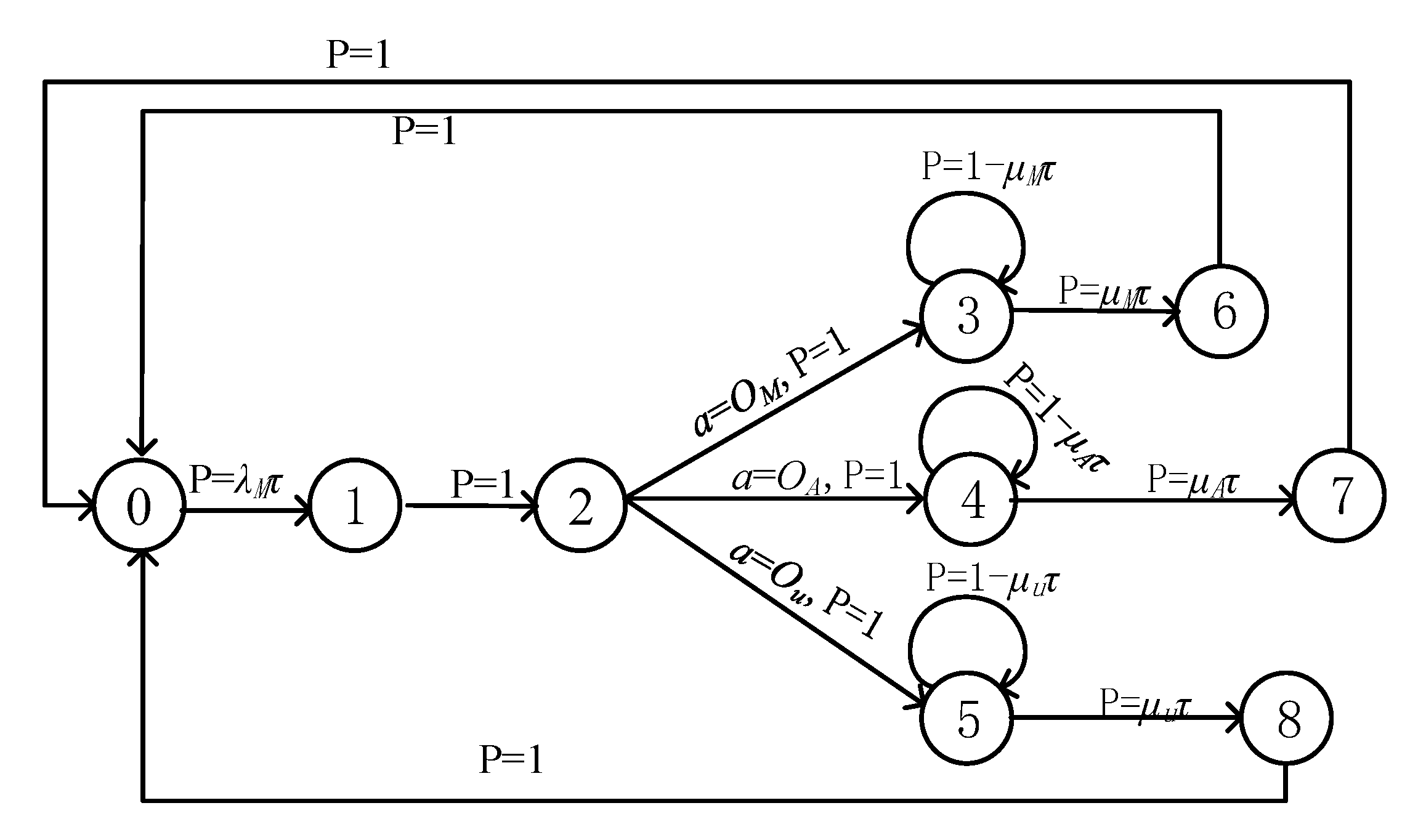
where m (M) denotes the phase of the task. If no task exists, then m = 0. m = 1 and m = 2 refer to the situation immediately after the task occurs and when the task is in the buffer (i.e., when task processing is not in progress), respectively. Meanwhile, m = 3, m = 4, and m = 5 represent the situations wherein the task is processed in the terminal equipment, the UAV, and the G-MEC, respectively. Additionally, m = 6, m = 7, and m = 8 represent situations immediately after the task processing is completed at the central cloud, the UAV, and G-MEC, respectively.
L can be constructed using a map segmentation technique [
25]. The UAV moves randomly within the area of the segmented position.
L is described as follows:
where
NL represents the total number of locations the UAV can locate.
Li represents a vector of adjacent cases, which is given as following:
If position i is adjacent to position j, then lji is 1; otherwise, lji is 0.
Meanwhile, network connection vector C is described as follows:
where
NC represents the total number of
k heterogeneous network connections and
NC = 2
k.
Cχ represents the
χth possible network connection given by
Cχ = [
c1,
c2,
c3, …,
ck]. A connection is indicated by
cζ = 1, whereas
cζ = 0 indicates a lack of connections.
3.2. Decision Action
When the task state is a buffer period (
m = 2), the algorithm determines the processing mode of the task or the decision action. The algorithm determines that tasks are local computing, UAV computing offloading, G-MEC computing offloading, or task delay processing. Action set
A is given as follows:
where
OM is the G-MEC computing offloading,
OA is the UAV computing offloading,
Ou is the local computing, and
D is task delay processing.
3.3. Transfer Probability
The task phase can be changed by the selected decision action, that is, T is affected by decision action A. At the same time, when a mobile device location is given, the available network at that location is also obtained. Therefore, the
T and
C states are interdependent. Thus, for the chosen action
a, the transition probability from the current state
s = [
m,
Li,
Cχ] to the next state
s′ = [
m’,
Lj,
Cχ’] can be described as follows:
Next, the transfer probability of different task stages M is analyzed, and τ indicates the duration of each decision period. We assume that the inter-arrival rate of the task follows an exponential distribution with mean 1/λM. Meanwhile, when m = 1, m′ will always be 2, so the transfer probability from m = 1 to m = 2 is 1.
When m = 2, the decisive action will affect the transfer probability and the next state. When the task decides to conduct delay processing (a = D), the task state will not change. When the task decides to conduct G-MEC offloading (a = OM), the task state will be converted to m = 3. When the task decides to conduct UAV offloading (a = OA), the task state will be converted to m = 4. When the task decides to conduct terminal processing (a = Ou), the task state will be converted to m = 5. When the processing task policy is determined, the transfer probability to the next state is 1.
During the offloading computing tasks, the BER and interruption problems caused by relay forwarding and long-distance communication will reduce the probability of the successful transmission of computing tasks. Calculating the state of the UAV after offloading and the resource situation of the G-MEC will also affect the probability of task computation completion. After the task is offloaded, the state of the UAV and the resource situation of the G-MEC will also affect the probability of task computation completion.
The probability that the task successfully completes the offloading calculation, which is affected by the communication transmission and computing resources, is not always 1. In other words, the transition probability of selecting the offload node state that transfers to the state that successfully completes the task calculation is not 1. In this study, the transfer probability of selecting the offload node state to the next state, that is, the transfer probability of the state
m = 3, 4, and 5 transferring to the state
m = 6, 7, and 8, is defined as the reliability index of the system accomplishing the task. The reliability index
μ is given by
μ = {
μM,
μA,
μu}, where
μM,
μA, and
μu are the indexes of the G-MEC offloading, UAV offloading, and terminal processing, respectively. The reliability index indicates the possibility of successful computation after the task decision is offloaded. The transition probability of task completion is shown as follows:
The definition of the reliability index endows the transfer probability with the physical meaning of the model. The definition means the size of the cost function and reward function affects the terminal decision of the offloading node, and the reliability index will influence the choice of the offload node. Thus, the application of the MDP algorithm is practical for the model. After the task completion phase,
m′ will always be 0, and the transfer probability is 1.
Figure 4 depicts the transfer probability distribution.
When the network topology and the residence time at each location are given,
P[
Lj,
Cχ’|
Li,
Cχ] can be obtained. We assume that the residence time in
Li follows an exponential distribution with mean 1/
ηi [
23]. The transfer probability can be obtained as follows:
where
Pij is the probability that the UAV moves from location
i to another location
j [
26].
3.4. Utility Function
After determining the transfer probability, the integrated cost function considering the energy consumption and delay in the model is introduced into the MDP algorithm. First, the total utility function is defined as follows:
where
f(
s,
a) and
g(
s,
a) are the reward functions for task completion within the deadline and the integrated cost function of the tasks, respectively.
φ1 represents the weight factor of the reward function and the cost function in the utility function. The cost function consists of energy consumption cost and delay cost, which is given as follows:
where
φ2 is the weight factor in the cost function for the delay and energy consumption costs. The transmission delay and energy consumption cost functions are determined by the offloading decision. The total utility function is related to the cost and reward functions, and the total utility function can be obtained by Algorithm 1.
| Algorithm 1 Reward function algorithm |
1: Set B, h0, σ, v, Tdeadline, Edeadline, δu, Pu, δuav, Puav, δGMEC
2: Initialize Z, d, Eu-c, Elevel
3: Step 1: Calculate Nz, Eu, Tu, Tuav, Euav-z, TGMEC, EGMEC-Z, Eu-r, Euav-z
4: Step 2: Calculate the award function
5: If (Eu-r < Edeadline & Tu < Tdeadline)
6: then, f(s, Ou) = Rou
7: else
8: f(s, Ou) = 0
9: end if
10: If (Euav-z, < Edeadline & Tuav-z < Tdeadline)
11: then, f(s, OA) = Rouav
12: else
13: f(s, OA) = 0
14: end if
15: If (TGMEC-Z < Tdeadline)
16: then, f(s, OM) = RoG-MEC
17: else
18: f(s, OM) = 0
19: end if
20: Step 3: Normalized utility function
21: E0 = {Eu,0, Euav-z,0, EGMEC-Z,0},
T0 = {Tu,0, Tuav-z,0, TGMEC-Z,0}
22: Step 4: Total utility function
23: q(s,a) = φ1 f (s,a) − (1 − φ1) [φ2 T0(s,a) + (1 − φ2) E0(s,a)] |
3.5. Optimal Equation
We choose the expected total discount reward optimality criterion as our objective function to maximize the expected total reward and obtain the optimal policy. Then, v(s) can be expressed as follows:
where
is the expected total reward when the policy π with an initial state
s is given.
Notably, when the terminal equipment takes the most beneficial action
a, the expected total reward can be maximized, and such an optimal action
a can be obtained in each state by solving the objective function. The optimality equation is given as follows:
where
λ is a discount factor in the MDP model, and
λ closer to 1 gives greater weight to future rewards. The algorithm aims to identify the best resource optimization strategy in the proposed multilevel offloading model, that is, the UAV relay. To solve the optimization problem and identify the best decision mentioned above, this study applies Algorithm 2.
| Algorithm 2 Resource optimization algorithm |
1: Set v0(s) = 0 for each state s. Specify ε > 0. χ = 0
2: Input: q(s,a), P[s’|s, a]
3: Step 1: For each state s, Calculate vχ+1(s)
4:
5: Step 2: If
6: then, Go to Step 3
7: else
8: χ = χ + 1
9: Go to Step 1
10: end if
11: Step 3: For each state s, compute the stationary optimal policy
12:
13: Stop. |
Given the complexity of the algorithm, the decision-making time cannot be ignored. Supposing the channel is quasistatic, the terminal equipment can use a table to store the best offloading strategy for the tasks computed by the MDP algorithm. This table includes the best decision for each state of the computing task, which can be obtained by pre-calculation. Hence, the decision time of this algorithm is short and will not affect the task calculation [
27].
4. Discussion
This section evaluates the performance of the proposed MENROM based on the MDP algorithm. The simulation results are presented, and the key parameters are analyzed. In the network environment, the UAV as a MEC server or relay node is arranged between the terminal equipment and the G-MEC at a distance of
H from the ground. In the terminal equipment, the calculation tasks of different sizes are selected for simulation analysis to verify the offloading mode and performance of the system. The simulation settings are based on the work of [
16], [
21], and [
22].
Table 1 shows the detailed simulation parameters unless otherwise specified.
With regard to the network environment in the model, heterogeneous networks include Wi-Fi networks and cellular networks (4G/5G), where the service coverage of the cellular networks is larger than that of the Wi-Fi counterparts [
28]. That is,
Cχ = [
c1,
c2] and and
Pij = 1 in the model, where
c1 and
c2 represent Wi-Fi and cellular networks, respectively. The average residence time of the Wi-Fi and cellular networks can be obtained according to the network performance evaluation [
29], and 1/
η1 and 1/
η2 are set to 10/6 and 10/4, respectively. The time slot length
τ is set to 1. The probabilities of the random occurrence of energy levels 1, 2, 3, 4 (that is
Elevel = 1,
Elevel = 2,
Elevel =3, and
Elevel = 4) are 0.15, 0.35, 0.3, and 0.2, and the corresponding energy level weights ω
1 = ω
2 are 0.8, 0.7, 0.6, and 0.5, respectively. The path decay index
q is 4.
For the comprehensive consideration of multiple situations, the effects of the key parameters were analyzed, including the system utility function, reliability index (μ), UAV initial energy level state (Elevel), delay and energy weight factor (φ2), and the UAV relay transmit power (Puav).
4.1. Performance Comparison of Different Scenarios
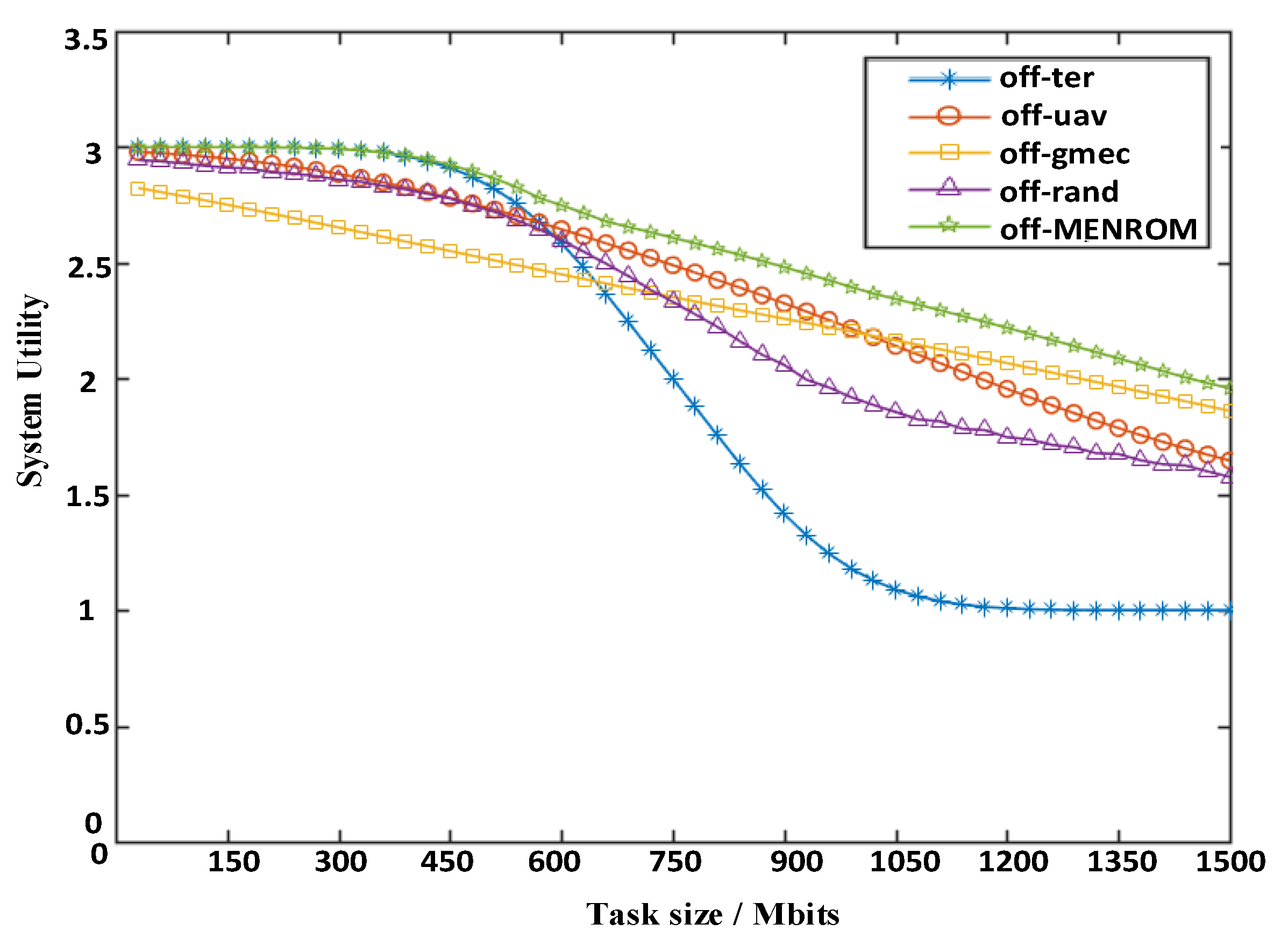
To illustrate the effectiveness of the model design, this model is compared to several other scenarios designed as follows: (1) terminal computing task off-ter, where the terminal only calculates tasks locally; (2) the UAV computing task off-uav, where the terminal only offloads tasks to the UAV for computation; (3) the G-MEC computing task off-GMEC, where the terminal only offloads tasks to the G-MEC for computation; (4) the random offloading off-rand, where the terminal randomly selects any uninstall node for the computing task; (5) the multilevel offloading on the basis of MDP off-MENROM.
Figure 5 shows the simulation results.
As shown in
Figure 5, the utility function decreases with the increase of the task size when the model considers the energy level and delay parameters. The utility of the off-MENROM is always the largest. When the task is small, the off-ter utility is close to the off-MENROM utility. Conversely, when the task is large, the off-MEC utility is close to the off-MENROM utility. When the task increases, the system utility function decreases gradually because of the increase in computational cost. The multilevel offloading model can obtain a better utility value compared with other offloading methods, thereby indicating that the multilevel offloading model can save system costs, ensure user QOS, and optimize system resource allocation. When the task is small, the utility value of the terminal local computation is closer to the utility value of the best offloading mode. Meanwhile, when the computing task is large, the utility value of the task offloaded to the G-MEC after the UAV relay is closer to the utility value of the best offloading mode, that is, a larger task is suitable for off-GMEC offloading.
4.2. Terminal Offload Selection
Task size affects network utility, terminal decision, and resource optimization results. The model offloading reliability index represents the probability that the task is successfully offloaded, and the completion is calculated. This index will affect the terminal device offloading decision. Three types of reliability indexes are designed for simulation analysis as shown in
Table 2.
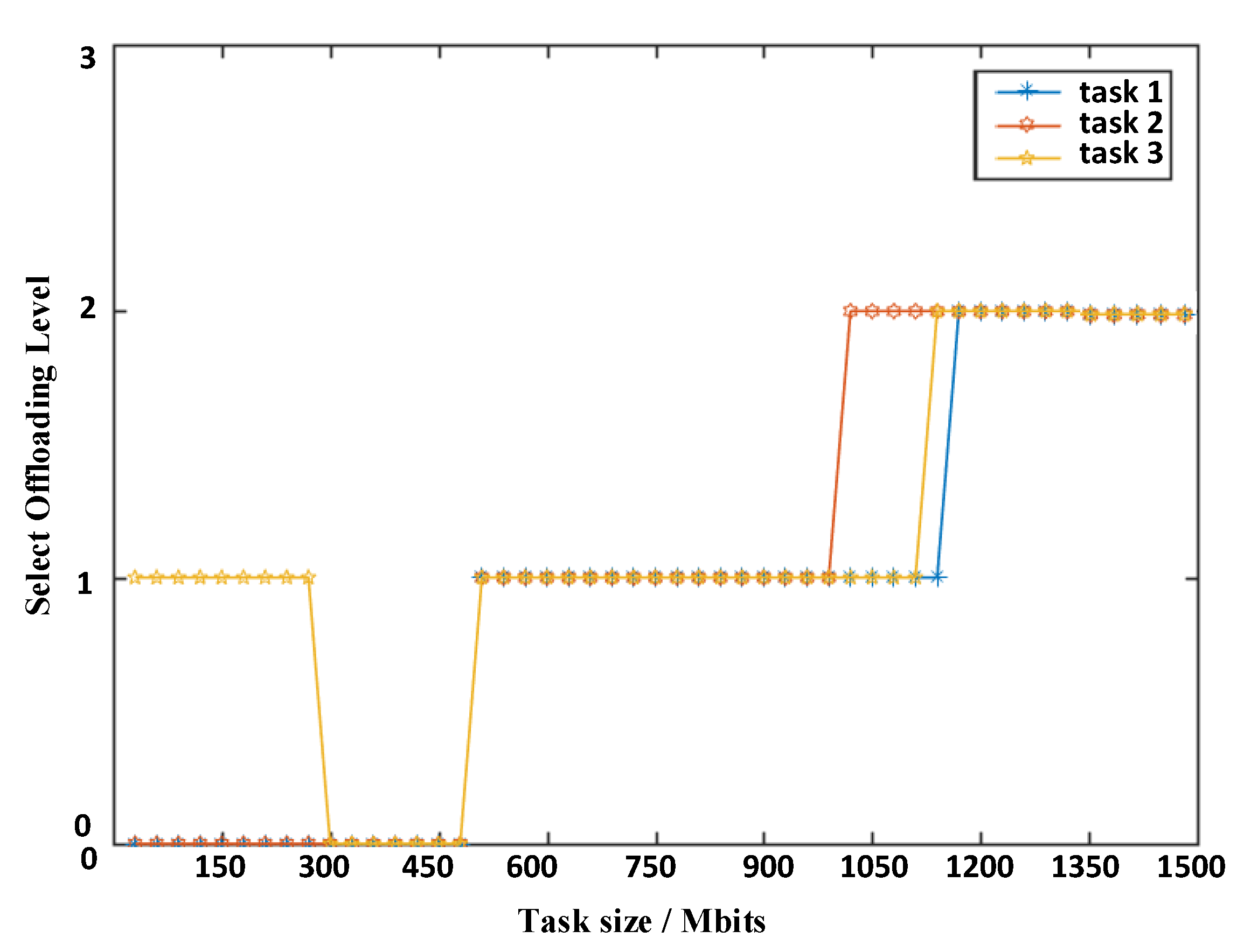
Arranged from largest to lowest, the above indexes are listed in the order of the terminal computing reliability index, the UAV offloading reliability index, and the G-MEC offloading reliability index in Task 1. For Task 2, the three types of offloading have the same reliability. For Task 3, the reliability index of UAV offloading is slightly higher.
Figure 6 shows the simulation results.
In
Figure 6, as the task increases, the decision of the terminal for the offloading node differs. “0” represents zero-level offloading (Level 0), in which the terminal performs the task computation processing. “1” represents the first-level offloading (Level 1), in which the UAV performs the task offloading. Finally, “2” represents the second-level offloading (Level 2), in which the G-MEC performs task offloading. As the task grows, tasks 1 and 2 begin to select Level 0 offloading, then Level 1 offloading, and finally, Level 2 offloading. Task 3 involves tasks in the following order: Levels 1, 0, 1, and 2 offloading. According to the above phenomenon, when the task is small, the terminal computing resource cost is the lowest, and the model will select the terminal for local calculation. When the task increases, a better system utility and resource allocation can be achieved by task offloading at the UAV. When the task is particularly large, the UAV and the terminal will be unable to undertake the task calculation, task offloading to the G-MEC is more reasonable, and the system benefits more.
As the reliability index of the UAV offloading is slightly higher than that of the terminal, Task 3 is a special case. When the task is small, the reliability index of the calculation is more important than the cost factor. Later, tasks increase, and the impact of the cost resource factor is greater than the reliability index. Therefore, the offloading level selection shown in
Figure 6 will be generated.
As the task increases, Task 2 initially offloads to the G-MEC, then Task 3 offloads to the G-MEC, and finally, Task 1 offloads to the G-MEC. The reliability index will affect the integrated offloading decision when the reliability index is high, and the task will choose to offload ahead of time (that is, the system utility is less when the offloading mode is selected).
4.3. Energy Level Analysis of the UAV
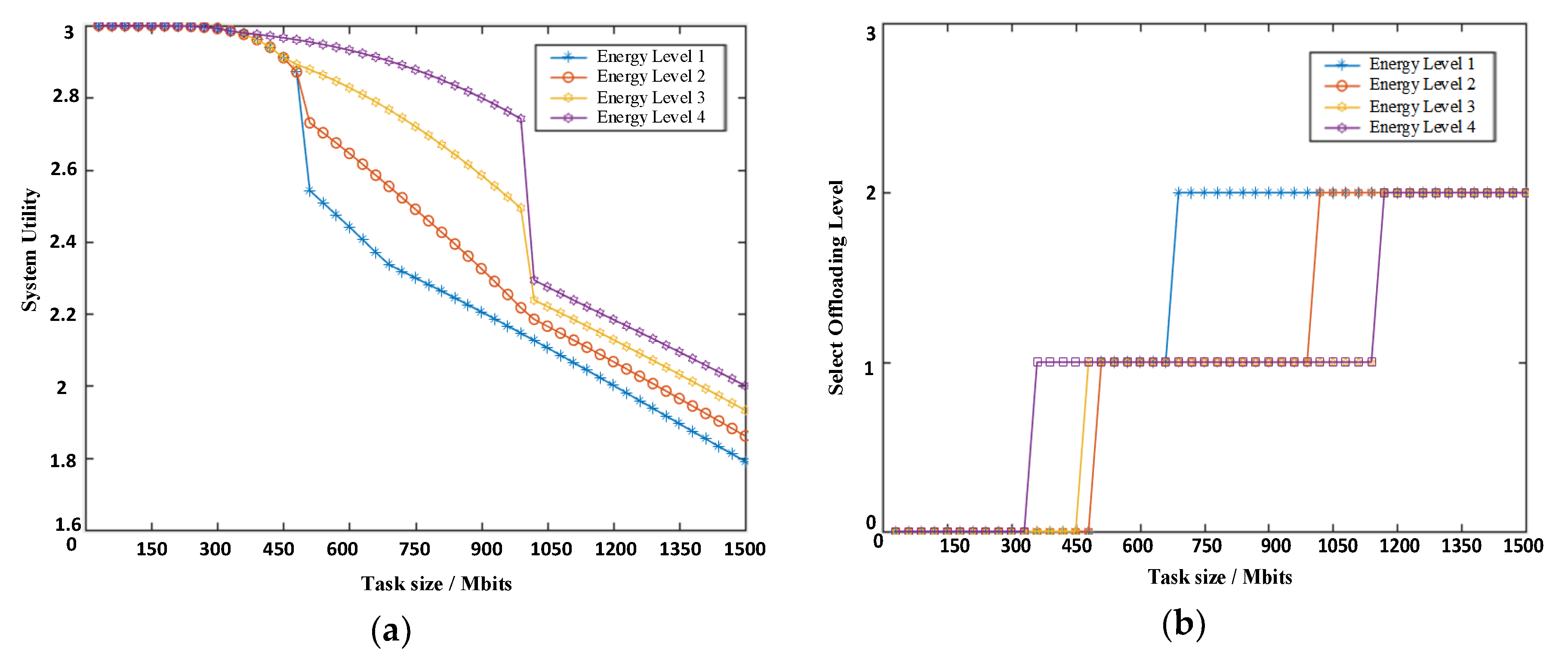
According to the model, the UAV as edge computing server and relay node assumes important functions. The UAV is at four energy levels due to the green energy charging and fixed battery energy storage. This section analyzes the effects of the four energy levels on system utility and offloading decisions. The reliability index is the same as the Task 2 parameter, and the energy level weight is initialized as above.
Figure 7 depicts the simulation analysis.
In
Figure 7a, when the task is small, that is, the computing task is processed at the terminal, and no UAV intervention is present, almost no gap exists in the system utility function. As the computing task increases, if the energy level is efficient, then the function is also efficient. Thus, the high energy level UAV has low energy costs and can provide better resource optimization. The effect of energy level on the utility function when the UAV acts as a relay node is less than such an effect when the UAV acts as an edge server. The UAV as a relay node can reduce the burden of energy and optimize system resource allocation.
In
Figure 7b, when the UAV is at a high energy level, more tasks will be offloaded on the UAV. When the UAV is at a low energy level, the task will abandon the UAV offloading when it is smaller and select second-level offloading. The UAV energy level will affect the decision-making of the terminal. The tasks are more willing to offload on the UAV at high energy levels. Conversely, offloading the task on the UAV at low energy levels will result in small gains.
4.4. Effect of φ2
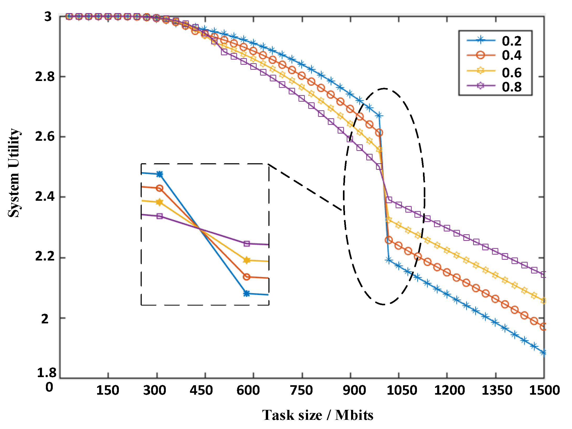
The weight factor φ2 determines the relationship between the delay and energy costs and the total utility function, thereby affecting the system resource optimization decision. The UAV is at energy level 3, and the reliability index is fixed.
In
Figure 8, the weight factor
φ2 is 0.2, 0.4, 0.6, and 0.8. The changing trend of the system utility function is shown as the task increases (
Figure 8). The task is medium-sized, and the smaller weight factor corresponds to a higher system utility. Moreover, when the task is large, the larger weight factor corresponds to a higher system utility. This situation arises because when the UAV is at energy level 3, the UAV has more available energy, and the higher weight of the delay cost will lead to a larger total cost and a lower utility function. Second-level offloading increases the system’s multiple energy consumptions compared with first-level offloading, and the high delay cost weight will reduce the system cost caused by high energy consumption. When switching offloading methods, the switching slope also varies because the weight factor has different effects on the system utility.
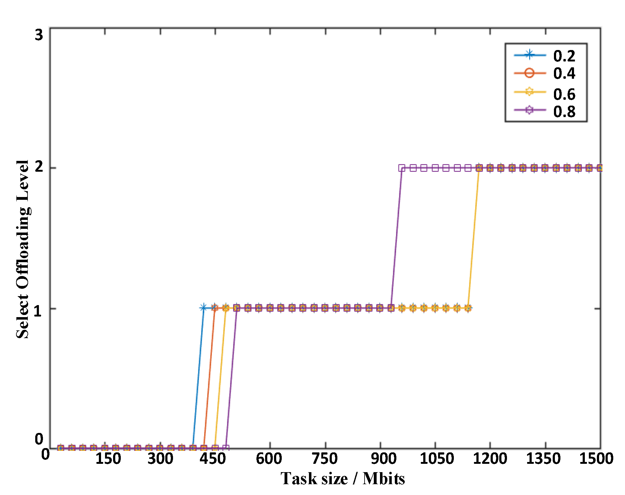
Figure 9 illustrates the choice of the task offloading policy in relation to weight and task size. As shown in
Figure 8, the system pays different attention to the delay and energy consumption under different weight values, so the utility of the system varies, thereby resulting in a selection strategy calculated according to the MDP, which also varies. When
φ2 has the intermediate values of 0.4 and 0.6, the systems are more likely to select first-level offloading.
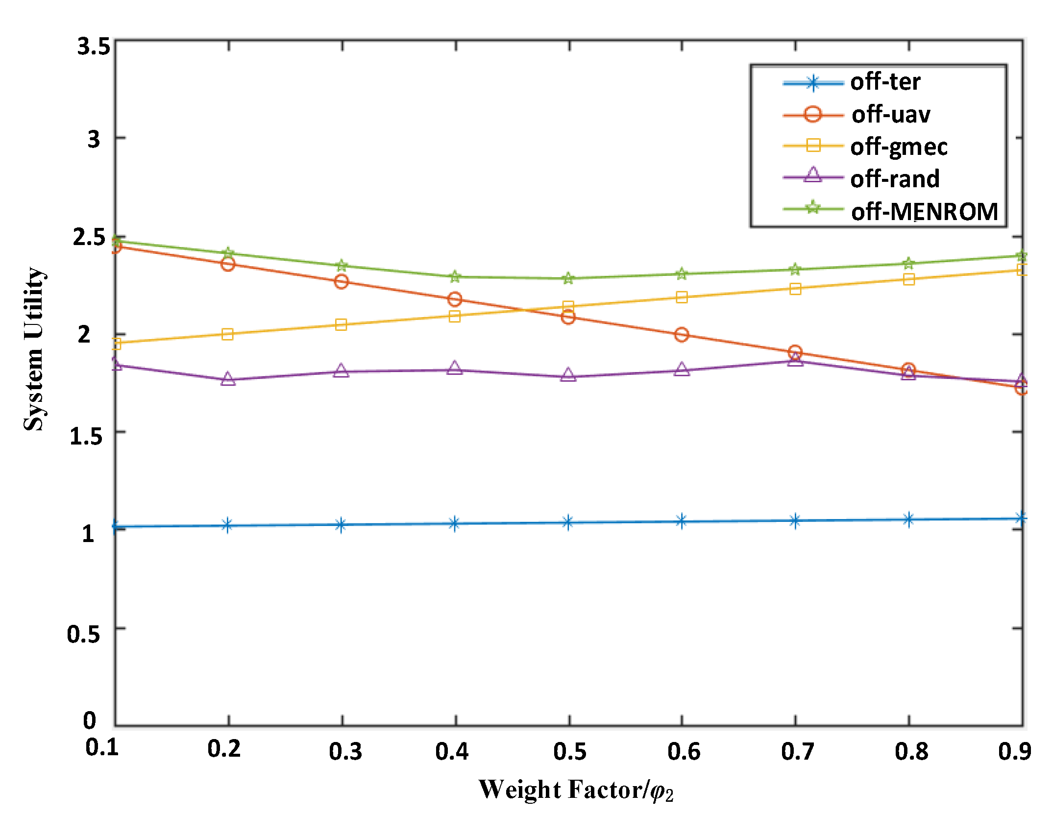
Figure 10 shows the effect of the weight factor
φ2 on the five scenarios with average utility functions in the case of a fixed task size with random UAV levels. In the UAV offloading scenario, the utility function decreases as the weight factor
φ2 increases. In off-uav, the utility function increases with the increase of the weight factor
φ2. The utility function of off-MENROM is superior to the utility function of the rest of the scenarios and is less affected by
φ2. The off-MENROM is less influenced by weight factor
φ2, and the utility function is more stable. Whether the system has a tendency to delay or energy, off-MENROM can identify a suitable offloading strategy and ensure system performance and reliability.
4.5. Optimization of the Relay UAV Transmit Power
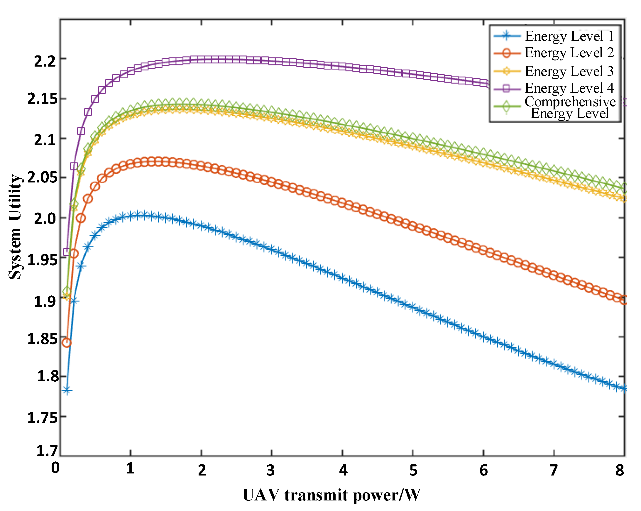
The relay UAV transmit power will affect the data transmission rate and energy consumption of the UAV. According to Equations (7) and (18), the transmission power is inversely proportional to the transmission rate, inversely proportional to the delay, and proportional to the energy consumption. Therefore, the system should have the best transmission power to achieve the lowest cost and the highest utility.
Figure 11 shows the relationship between the UAV transmission power and the system utility function at different energy levels. As the UAV transmit power increases, the system utility function initially increases and then decreases, so the network must have the best UAV transmit power to maximize the utility function. The optimal transmission power is approximately 1W, but the specific value cannot be obtained (
Figure 11). Optimizing the UAV transmission power and using resources efficiently are noteworthy directions for future research.
