Review

Leakage Current Reduction in Single-Phase Grid-Connected Inverters—A Review

by
Adyr A. Estévez-Bén
1,†,
Alfredo Alvarez-Diazcomas
2,†,
Gonzalo Macias-Bobadilla
2,† and
Juvenal Rodríguez-Reséndiz
2,*,†
1
Facultad de Química, Universidad Autónoma de Querétaro, Cerro de las Campanas, S/N, Col. Las Campanas, C.P. 76010 Querétaro, Mexico
2
Facultad de Ingeniería, Universidad Autónoma de Querétaro, Cerro de las Campanas, S/N, Col. Las Campanas, C.P. 76010 Querétaro, Mexico
*
Author to whom correspondence should be addressed.
These authors contributed equally to this work.
Appl. Sci. 2020, 10(7), 2384; https://doi.org/10.3390/app10072384
Submission received: 28 February 2020 / Revised: 26 March 2020 / Accepted: 27 March 2020 / Published: 31 March 2020
(This article belongs to the Special Issue Advancing Grid-Connected Renewable Generation Systems 2019)

Abstract

:
The rise in renewable energy has increased the use of DC/AC converters, which transform the direct current to alternating current. These devices, generally called inverters, are mainly used as an interface between clean energy and the grid. It is estimated that 21% of the global electricity generation capacity from renewable sources is supplied by photovoltaic systems. In these systems, a transformer to ensure grid isolation is used. Nevertheless, the transformer makes the system expensive, heavy, bulky and reduces its efficiency. Therefore, transformerless schemes are used to eliminate the mentioned disadvantages. One of the main drawbacks of transformerless topologies is the presence of a leakage current between the physical earth of the grid and the parasitic capacitances of the photovoltaic module terminals. The leakage current depends on the value of the parasitic capacitances of the panel and the common-mode voltage. At the same time, the common-mode voltage depends on the modulation strategy used. Therefore, by the manipulation of the modulation technique, is accomplished a decrease in the leakage current. However, the connection standards for photovoltaic inverters establish a maximum total harmonic distortion of 5%. In this paper an analysis of the common-mode voltage and its influence on the value of the leakage current is described. The main topologies and strategies used to reduce the leakage current in transformerless schemes are summarized, highlighting advantages and disadvantages and establishing points of comparison with similar topologies. A comparative table with the most important aspects of each converter is shown based on number of components, modes of operation, type of modulation strategy used, and the leakage current value obtained. It is important to mention that analyzed topologies present a variation of the leakage current between 0 to 180 mA. Finally, the trends, problems, and researches on transformerless grid-connected PV systems are discussed.

1. Introduction

Nowadays, the increase in the world population, environmental pollution resulting from the burning of fossil fuels, and the need to deliver electricity to remote areas are factors that drive the use of renewable energy (RE). It is expected that these fundamental tasks and the fulfillment of international agreements related to the protection of the environment will be solved with the greater use of clean energy [1]. Solar, hydroelectric, and wind power are the primary sources that are being used by the new technologies [2].
Advances in electronic devices have led to an increase in power generation capacity from RE [
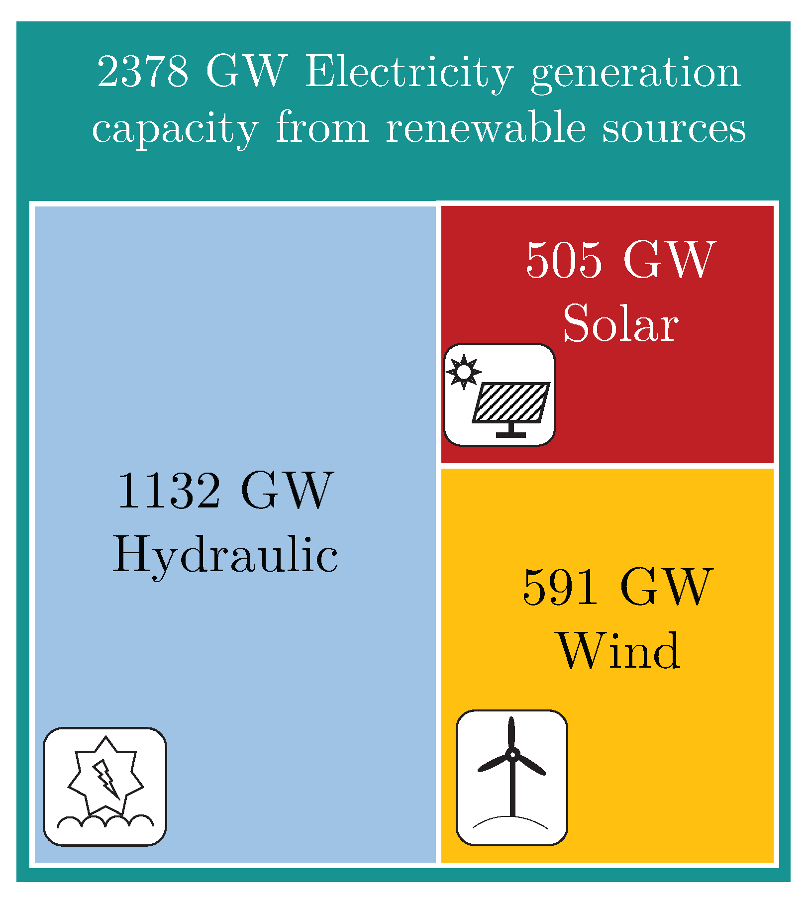
3]. In 2016, the main contributions came from the European Union with 106 GW (Germany 41.3 GW), followed by China with 77.4 GW, Japan with 42.8 GW, and the United States with 40.9 GW for a total of 303 GW [4]. The power generation capacity from solar energy, in 2018, exceeded 505 GW [5]. The fast development of photovoltaic (PV) cell technologies, the continuous reduction of module costs, as well as advances in power electronics, are factors that drive the use of solar energy over other renewable energies [6]. Figure 1 shows the power generation capacity from the main sources of RE.
The DC/AC converters are used in a wide variety of applications, from power supplies [7,8,9], to high-power industrial applications [10,11,12]. At present, they are also used as an interface for the control of motors for electric vehicles [13]. However, one of the most important uses is the transformation of the direct current generated by the photovoltaic panels, accumulators or batteries, into alternating current [14]. There are many points of view from which inverters are classified, one of the essential classifications is made according to their power supply. In this way, three types of inverters are established—Voltage Source Inverter (VSI) [15], Current Source Inverter (CSI) [16] and Z-Source Inverter (ZSI) [17]. As a summary, the main classifications of these power converters are presented in Figure 2.
It is important to note that the average lifetime of DC/AC converters is over five years [19]. Research focuses on developing more durable topologies, reducing the installation and maintenance costs of PV systems. In this sense, Reference [20] presents a method for the accurate sizing of stand-alone photovoltaic (SAPV) residential generation systems for a pre-established reliability level.
Grid-connected photovoltaic systems are typically categorized in two ways, with transformer and transformerless. For low-power applications, single-phase converters with a high or low-frequency transformer are generally used. It is possible to remove the transformer to reduce the weight, size, cost, and losses of the system. In this way, the efficiency of the inverter is increased by 1 or 2%. Therefore, the transformerless PV inverters are promising and attractive in industrial and academic fields [21]. However, due to the lack of galvanic isolation, high-frequency common-mode voltage (CMV) cause undesirable leakage current resulting in output-current distortion and safety trouble [22]. The leakage current depends mainly on the topology and the modulation strategy used. The main problems are—an increase in losses, current harmonics, safety issues, and interference problems of electromagnetic effect [23]. These problems have been reported in different papers [24,25,26,27].
At this point, it is established that the leakage current depends on the value of CMV, the modulation strategy and the value of the parasitic capacitance [28]. At the same time, parasitic capacitance depends on [29]:
  • PV panel and frame structure.
  • The surface of the cells.
  • The distance between cells.
  • Weather conditions.
  • Type of electromagnetic compatibility filter.
Three methods in general have been used to mitigate the effects of the leakage current [30]:
  • Disconnect the AC side and the PV during free wheeling times.
  • Connect the midpoint of the DC-link capacitors to the neutral line of the utility grid.
  • Connect the PV negative terminal to the neutral line of the utility grid directly, referred here as CM converters.
Transformerless inverters must eliminate, or at least, reduce the leakage current, for example, by including passive damping components or by modifying the modulation strategy [31]. In order to improve efficiency, transformerless topologies have been developed [28,32,33,34,35]. Generally, the inverters used in RE applications employ the VSI topology due to their low cost, easy control, and mature technology. The leakage current circulates through the physical earth of the grid and parasitic capacitances of each pole of the panel, as illustrated in Figure 3. This current impairs the functioning of the system, injecting harmonics into the grid and produces risks to human health.
The paper is structured as follows. In Section 2, the main standards and requirements of panels and inverters are presented. The VDE-AR-N 4105 and VDE 0126-1-1 standards establish the rules for grid-connected systems. An analysis of the common-mode and how it influences in the leakage current is performed in Section 3. Current research also seeks to reduce components number, control complexity and increase the inverters efficiency. Section 4 presents certain topologies that allow comparisons with similar schemes. This section also shows a general comparison of the different converters and their main features; in this way, the reader can differentiate each topology based on the most important elements of each scheme. Also, the discussion of current problems, solutions, and trends in this field of research are described.

2. Standards, PV Module and Inverter Requirements

The grid power supplied corresponds with the available energy sources account and the systems efficiency. However, a grid-connected generation system must meet specific standards, thus seeking to ensure a secure connection for both sides of the grid [36]. Each country or region sets its connection standards. In this section, two of the most used are addressed. In addition, certain requirements of the PV modules and inverter to be used are presented. By the way, the authors of Reference [37] show an analysis of the issues and impact of photovoltaic energy in the grid. The authors provides useful information, serves as a reference for researchers and utility engineers on issues to be considered with regards to PV penetration.

2.1. VDE-AR-N 4105 and VDE 0126-1-1 Standards

At present, specific standards regulate the generation systems connected to the grid. The code VDE-AR-N 4105 governs the implementation of the European Network Code Requirements for generators for the low-voltage (LV) grid in Germany. In general, the code describes the grid connection requirements for generators at all voltage levels [38]. The regulations include capabilities for frequency stabilization, provision of reactive power to the point of black start capacity of large installations.
According to VDE 0126-1-1 [39], an independent switching system is required capable of controlling the contribution to the 230/400 V grid from the photovoltaic installations. It must be possible to disconnect small power generators from the grid within 200 ms when the consumer or the protection device wishes to interrupt the connection. The voltage, frequency, and recognition controls of the service operations are the most demanded requirements at the automatic switching points. For this, a control and frequency relay is used that complies with the standard above at the automatic switching points between the power generators and the national low-voltage grid. Table 1 summarizes the main characteristics of both regulations and highlights the differences between them.
Figure 4 shows a general connection scheme for grid-connected PV systems. In this scheme, two crucial issues are raised, the minimum voltage control and the frequency at the grid connection point. Generally, there are protections systems that disconnect the system if its voltage supply is reduced by 35% of its nominal value.

2.2. PV Module Requirements

PV modules must meet a range of regulations and standards before they are considered suitable for sale and for renewable energy funding programs. PVs get their success due to long-term reliability and safety. On average, current PVs have a guarantee of use of around 25 years, with a degradation rate of 0.8%, based on international standards. An interesting study is presented in Reference [41] that analyzes the energy requirements for the production of PV and the generation throughout the useful life of the finished product. The research results showed that this technology is self-sustaining because it can generate several years of clean energy. In Reference [42], the standards for PV modules and components are summarized. In general, panels must comply with a range of international standards including IEC 61215, IEC 61646, IEC 61730-1/2, ISO 9000, ISO 14001. There are three types of main classifications for these PVs, which do an excellent job of identifying design, materials, and process flaws that could lead to premature field failures:
  • IEC 61215 for Crystalline Silicon Modules.
  • IEC 61646 for Thin Film Modules.
  • IEC 62108 for CPV Modules.
From the electronic point of view, in Reference [43] it is specified that ...The PV cell, and module, is hypersensitive to ripple in the output current and voltage. The ripple does not damage the PV cell, but it reduces the available power dramatically... According to [44], the maximum voltage ripple allowed for a PV is defined as:
Δ v = 2 ( K P V 1 ) P M P P 3 α V M P P + β = 2 2 ( K P V 1 ) P M P P d P P V 2 d V P V 2 ,
where Δ v is the voltage ripple, P M P P and V M P P are the power and voltage at maximum power point (MPP), P P V and V P V are the power and nominal voltage of the panel, α and β are the coefficients which describe the second–order Taylor approximation of the current and K P V is the utilization ratio which is given from the rate of average generated power to the theoretical MPP power. The coefficients are calculated as follows [43]:
i P V = α V P V 2 + β V P V + γ
V P V V M P P + Δ v s i n ( w t )
α = 1 2 d 2 I M P P d V M P P 2
β = d I M P P d V M P P 2 α V M P P
γ = α V M P P 2 d I M P P d V M P P V M P P + I M P P .
For example, for FS55 CdTe PV module, 55 W, the parameters are calculated according to the Equations (1)–(6) as: α = −0.0161, β = 1.0276, and γ = −11.7038. By setting K P V = 0.98, it is obtained that the system have a maximum ripple voltage of 7.96 V. This value represents a permissible voltage ripple of 13.05% of V M P P . The second-order ripple power must be taken into account, and this is inherent in single-phase systems. The power that is injected into the grid varies in time to twice the frequency of the grid; however, the energy extracted from the PV must be constant to maximize energy extraction [45], although a variation of 13.05% of the nominal voltage is permissible.

2.3. Inverter Requirements

Existing standards applicable to PV inverters mainly cover the objectives of ensuring wave quality, performance, electrical safety and compatibility with the grid and system operator requirements. Table 2 shows the standards and a brief description of their content.
The voltage value is one essential characteristic from which it is possible to identify if the system works correctly. Table A1 presents the international standards for normal operation in LV grid [46]. On the other hand, Table A2 summarizes acceptable voltage ranges according to EN 50438 by countries [47]. In countries with increased PV penetration (Germany, Spain and France), in normal conditions, the voltage limits specified by the LV grid codes should not exceed the limits expresses in Table A3 [48,49]. Frequency stability represents another crucial element in determining the correct operation of the system, in this regard, Table A4 specifies the frequency ranges in which the system can operate; also, the disconnection times are specified [50]. Other important aspects such as: limits of under/over frequency, the clearance periods and reconnection requirements are shown in Table A5, Table A6, Table A7 and Table A8. A survey of existing standards for inverters in certain IEA countries is given in Table 3.

3. Common-Mode Voltage Analysis

The use of transformers in the PV grid-connected systems guarantees isolation and eliminates the leakage current. These systems are expensive, heavy, bulky and low efficiency [51]. The current trend is focused on removing this device (transformer), in order to eliminate the aforementioned disadvantages [52]. However, removing the transformer is a new challenge, as the leakage current arises in the system. The leakage current is mainly affected by the variation of the voltage in common mode over time [53]. Taking as an example an inverter without transformer with complete bridge topology for a residential PV system connected to the single-phase grid, the equivalent CM circuit of Figure 5 is considered.
The analysis presented in [54], assumes that the negative (N) terminal of PV is the reference point and the midpoints of the bridge leg (1) and (2) as output terminals. From the definitions of differentiation mode, V C M and V D M is related as follows:
V C M = V 1 N V 2 N 2
V D M = V 1 N V 2 N
where: V C M is the common voltage, V D M is the differential voltage, V 1 N is the voltage between (1) and (N) and V 2 N is the voltage between (2) and (N).
Taking into account Equations (7) and (8), V 1 N and V 2 N are expressed as:
V 1 N = V C M + V D M 2
V 2 N = V C M V D M 2
The scheme in the Figure 6 illustrates the diagram of a current full-scale leakage analytical model considering the parasitic branch.
where: V C M D M indicates the influence of the differential mode voltage to the common-mode voltage.
At this point, it is seen that the common-mode voltage has a marked influence on the leakage current. Also, there is an additional common-mode voltage ( V d t o c ) that is defined as:
V d t o c = V D M L 2 L 1 2 ( L 2 + L 1 )
Taking into account Equation (11), the differential voltage with the unbalanced L 1 and L 2 inductors contributes to the common-mode voltage, increasing the leakage current.
V T C M = V C M + V d t o c = V 1 N + V 2 N 2 + V 1 N + V 2 N 2 L 2 L 1 ( L 2 + L 1 )
where: V T C M is the total high-frequency common-mode voltage.
By considering only one of the inductors ( L 1 or L 2 ), Equation (12) is reduced, for example, by considering only L 1 :
V T C M = V 1 N + V 2 N 2 V 1 N V 2 N 2 = V 2 N
Therefore, it is concluded that if L 1 = L 2 , then the common mode voltage is expressed as:
V T C M = V 1 N + V 2 N 2 = V C M
From the model presented in Figure 6, two rules are established to eliminate or reduce the leakage current in PV systems [54]:
  • For symmetrical power topologies with zero V C M M D , designing a sinusoidal pulse width modulation (SPWM) strategy to constantv CM.
  • Matching circuit parameters to make the sum of V C M M D and V C M be a constant.

4. Grid-Connected PV Inverter Topologies

In this section, different topology of latest generation photovoltaic inverters are presented. Essential aspects such as: modulation strategy, modes of operation, advantages and disadvantages are discussed. In addition, a summary table is presented that allows the comparison of each topology.

4.1. Common-Grounded Inverter

In transformerless systems, the use of common-grounded inverters is one of the most used topologies to prevent the leakage current. In these converters, the negative terminal of the PV is directly connected to the neutral point of the grid; therefore, the general CMV is removed correctly [55]. Today, other common-grounded schemes have tried to reduce the number of DC voltage sources by using capacitors [56]. Switched-Capacitor based inverters use the virtual dc-link concept to obtain two times boost factor within a single-stage operation without using any auxiliary inductors. For example, in Reference [57], a novel topology for the single-phase transformerless grid-connected inverters family is presented. This converter is shown in Figure 7.
This type of converter boosts the input voltage to double by using the one-stage SC, eliminating the disadvantages of two stages [58,59]. The presented design employs a unipolar PWM method and only has two energy levels at its output. Using unipolar PWM, the THD and the size of the inductor is be reduced [60], but V C M varies in the switching frequency of the inverter and its multiples [61]. The low impedance offered by the parasitic capacitance ( C P V ) between ground and PV at these frequencies, causes a higher common current than bipolar PWM [62]. Particularly in this paper, the topology eliminates the leakage current up to a value close to 0 mA.
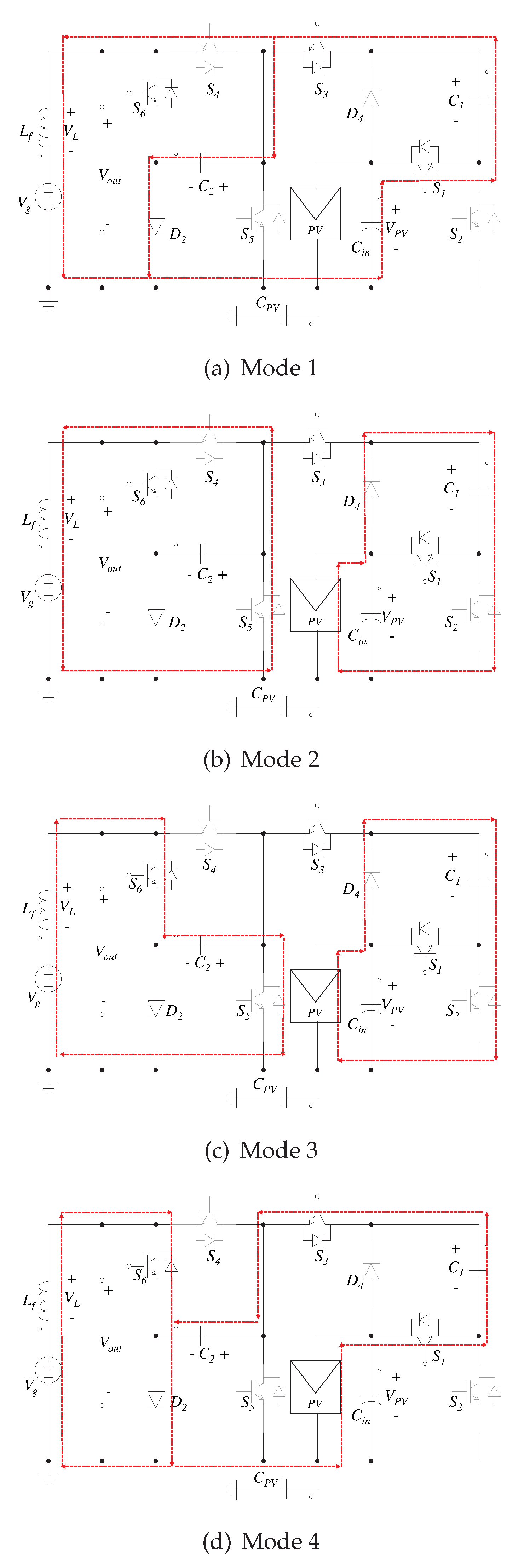
The four modes of operation of the proposed inverter are shown in Figure 8. The topology always maintains a connection between the negative terminal of the panel and the neutral of the grid. The switches use a switching frequency of 25 kHz. The capacitors will be charged both in the positive and the negative half-cycle; this feature allows the use of metalized polyester film capacitors or MKT capacitors instead of electrolyte capacitors.
The previous design has certain disadvantages; for example, the use of capacitors decreases the useful inverter life. Besides, it only has two levels of energy at the output (positive and negative), which increases the THD compared to inverters with more than two levels. On the other hand, the switching frequency can be considered high, causing the elements to wear and sometimes noise to the system. Compared to MLI, the topology must be used for low powers. SC-based multilevel inverters (SCMLI) are being addressed to increase the number of levels, decrease THD and increase the total power that this type of device can handle. New configurations of SCMLIs were suggested in the literature [63,64,65].
Another type of common-ground based inverter is the one that uses floating capacitors. In Reference [66], a Type-I inverter with two switches in series during the positive cycle is proposed. The authors of Reference [67] analyze Type-II and Type-III inverters. In the Type-I topology, only one switch carries the load current during the positive cycle. For its part, Type-III topology no requirement of an extra diode as in the previous two topologies to form a topology similar to a conventional H-bridge. The three topologies use unipolar SPWM as a modulation technique to reduce system losses, THD and output filter size. In all three cases, only four active switches are used to realize the basic inverter circuit and reduce the leakage current until practically eliminate it. The reduction in common-mode frequency has also been achieved using transformerless topologies with multilevel neutral point clamp [68] or its variant, using split inductors [69].

4.2. H5, H6 and HERIC Inverters

Current source inverters are used in high-power applications due to its high reliability, inherent short-circuit protection, and regenerative capability [70]. The VSIs are dominant due to low cost, simple control, and mature technology. Usually, in residential renewable power generation systems such as PV systems, VSIs are of most employed [71]. The difference between VSI and CSI lies in the type of DC source from which they take their energy. The basic concepts and operations are different for each inverter. Some CSI topologies have been shown in recent research [72,73,74]. Nowadays, CSI topologies try to reduce the leakage current, such as H5 [75], H6 [76] and HERIC [77].
In Reference [78], three similar topologies of transformerless current source inverters (full-bridge, H5 and H6 topologies) are compared to highlight their differences. The analysis makes a comparison considering the efficiency, the leakage current and the quality of the output current. In the paper the most important conclusion could be: ...among the topologies examined, inverter H5 seems the best compromise in terms of efficiency, reduction in the leakage current, number of components, and current quality...
In Reference [79] a novel transformerless dual-buck full-bridge grid-connected inverter (GCI) with H5-type (TDFGI-H5) topology for PV systems is presented. The topology shows that TDFGI-H5 has the advantages of the three-level output, no shoot-through problem, high reliability, and can completely meet the condition of eliminating common-mode leakage current. Figure 9 shown the proposed inverter.
The modes of operation presented in Figure 10 depend on the direction of the grid current ( i g ) . Acting on the switches ( S 1 S 5 ) , TDFGI-H5 can be divided into four operating modes. In this case, according to the authors in [80,81], the leakage current is defined as in Equation (15). However, during the operating modes u e c m = u G N and u G N remains constant. Therefore, the leakage current is eliminated.
i t c m = C G d u e c m d t = C G Δ u e c m Δ t .
In the paper, unipolar SPWM is used, which, in combination with the topology and control strategy, keep the common-mode voltage constant. It is important to point out several features of this design. This topology has a more significant conduction loss than its BDFGI counterpart. The inductors used have a longer useful life than the capacitors. Current research is working to reduce the size of the storage elements since it makes the system more expensive, bulky and bright than VSI.
Despite the advantages mentioned in the previous topology, the H6 topology is the only one that has bidirectional capability [82]. In Reference [76], an unusual topology is shown whose challenge is to find an efficient solution to the bidirectionality of this type. As a result, the research uses a hybrid modulation strategy, both for the rectifier and the inverter. Among the most relevant results is the possibility of extrapolating the modulation strategy proposed for similar topologies.
The highly efficient and reliable inverter concept (HERIC) inverter is a cost-effective topology, which has low leakage currents and relatively high efficiency. Among various transformerless topologies, the HERIC is a promising candidate due to the simple structure and high efficiency. In Reference [77], a unipolar modulation strategy for a HERIC inverter is presented. The proposed method takes the advantages of the conventional UP-PWM, the UP-PWM with dead time, and the modulation strategy of reactive power capability. To further improve power quality, the effects of the dead time and minimum pulse width limitation were compensated through the hybrid UP-PWM scheme.

4.3. Single-Stage Buck-Boost Inverters

Generally, topologies can only offer the same input voltage at the output, for example, traditional buck inverter-based topologies. However, many applications require to boost the input voltage for proper operation. The main differences between the buck-boost inverter topology with traditional full-bridge buck inverter and boost inverter are summarized in Reference [83]. The conventional full-bridge inverter is a converter that does not produce a larger output at the input but is easily controlled. For its part, the boost inverter, like the buck-boost inverter, generates an AC output higher than the input, controls the duty cycle.
Recent research focuses on designing a single-stage buck-boost inverter topology [84,85,86], basically to reduce the number of components such as switches; also, the two-stage power conversion results in the complex circuit structure and control algorithm [87]. Generally, single-stage buck-boost inverters consist of distinct circuits operating individually in buck/boost or positive/negative modes, the latter leading to crossover distortion in the output current [88]. Usually, in a single stage, an output peak ac voltage higher than the input dc voltage is obtained by using a full-bridge inverter followed by a low-frequency step-up transformer. However, the bulky transformer increases the volume, loss, and system cost [89].
This type of converter compensates for variations in renewable energy sources, such as: shading, irradiance, cloudiness and temperature. Other typologies may offer similar results to these natural variations, for example, the traditional full-and-bridge inverters followed by a boost-type DC/DC converter. However, it requires multiple inductors and capacitors for the same result. The differential boost inverter presented in Reference [90] provides buck-boost operation in a single-stage from two identical DC/DC boost converters. This topology employs two inductors; all its switches operate at high frequency, and it has no common ground.
In Reference [91], a single-stage bidirectional buck-boost transformerless inverters using a single inductor and eliminating the common-mode leakage current is proposed. The scheme is shown in Figure 11 has two input supplies, these supplies can have the same or different voltage value, so the topology allows to obtain the energy from several types of clean sources. The authors highlight that due to its buck-boost ability, one of the advantages of the proposed inverter is its capability of generating a sinusoidal output voltage even if V i n 1 V i n 2 . Another variant is also described in the same work, an inverter from a single input source. This scheme is similar to the traditional half-bridge inverters [92], noting that it does not require a higher input voltage, with the use of two capacitors C 1 and C 2 .
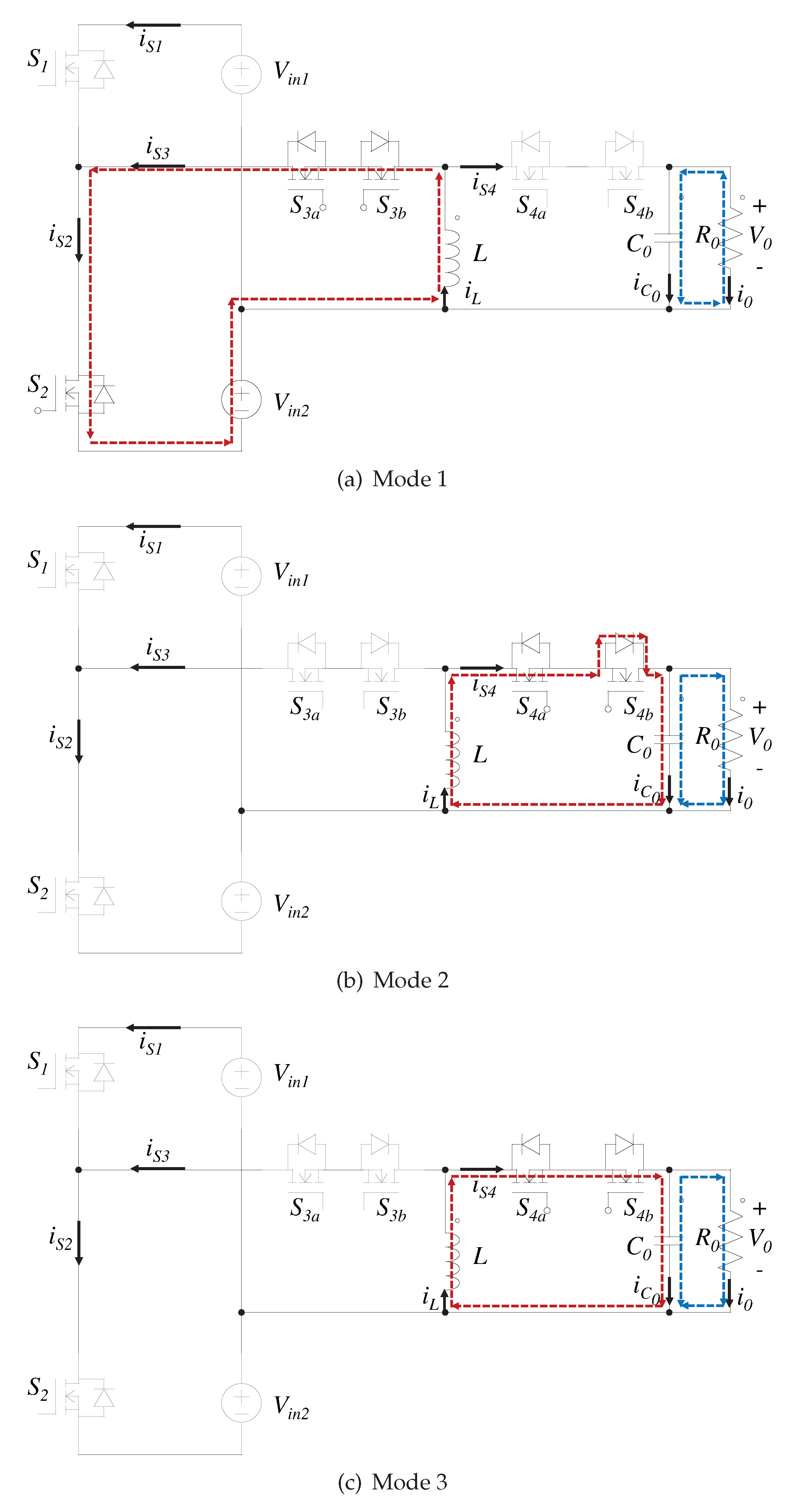
The modes of operation are presented in Figure 12. The inverter has 3 modes of operation, which make it bidirectional and can provide reactive power. The paper points out that the leakage current is reduced since the output voltage ( V 0 ) is low frequency sinusoidal ac voltage, V i n 1 and V i n 2 are dc constant voltages and the values of the parasitic capacitances are extremely small.
The scheme presented requires a higher number of devices compared to the other topologies presented up to this point. Besides, it is valid to specify that, although two of its switches operate at a low-switching frequency S 1 and S 2 and conduction losses are negligible in this case, two other switches S 3 and S 4 operate at one high-switching frequency. In the latter case, the losses are due to the discharge of the junction capacitor C o s s . The work shows an important comparison of the buck-boost inverters. The comparison summarizes some of the essential features of this type of converter: common-mode leakage current, bidirectional operation, components amount, operated as grid-connected or stand-alone.
At present, several investigations have been developed that address the topology in question. A combination of a front-end boost stage, a half-bridge inverter stage, and a buck-boost power decoupling stag is proposed in Reference [93]. It requires two capacitors that function as independent sources, and only one of them is used at a time. In Reference [94] a novel single-stage full-bridge series-resonant buck-boost inverter (FB-SRBBI) is proposed. In this case, a greater number of devices conduct at the same time, thus increasing conduction losses. A new transformerless single-phase single-stage buck-boost grid-connected VSI topology is proposed in [95]. Each mentioned topology has advantages and disadvantages. The scheme to use depends on the application.

4.4. Comparative Study

The section presents a comparative Table 4 of the inverter topologies connected to the grid currently used. Some works show a significant reduction in leakage current. This reduction is achieved by combining the design with the control strategy. The type of converter, the number of components, modes of operation, the output filter, the input voltage, the modulation strategy, and finally, the leakage current reported are summarized, according to the experimental results.
In Reference [57] a comparative table is presented, which also highlights the maximum average current of the switches and the overall efficiency of the system. The research [108] also shows a comparative study with structures similar to transformerless single-phase single-stage grid-tied flying inductor inverters.

5. Conclusions

The rise in renewable energy has caused an increase in the use of inverters. These devices are used as an interface between the power source and the grid. Moreover, it is common the use of transformers to have electrical isolation between the input and output. However, these elements are expensive, bulky, heavy, and have magnetic losses. Transformerless inverters have been developed to avoid the aforementioned limitations. One of the main drawback in this type of topologies is the presence of a leakage current between the terminals of the photovoltaic cell and the physical ground of the grid.
The paper presents a general review of the state-of-the-art of grid-connected inverters with leakage current reduction. Moreover, the main standards of the PV modules and inverters are presented. The behavior of the CMV, its origin and effect in transformerless grid-connected inverters are analyzed. Also, a comparative analysis of the most common topologies is performed. Finally, the main challenges and research trends within this topic are highlighted. Hopefully, this review will lead to increased efforts in the research and investigation of leakage current reduction in transformerless inverters.
In this paper, it is concluded that grid-connected systems have to comply with specific standards for each region or country. A THD less than 5% and a leakage current less than 300 mA are some of the most important standards to consider. Moreover, the output of the PV requires particular attention, since it presents a voltage ripple that do not damage the PV cell, but it reduces the available power. Furthermore, the unbalance in the inductors of the output filter increases the leakage current. The unbalance in the inductors is due to a dispersion in the capacity, aging rate and temperature behavior of the output inductors. These factors must be considered in the design of the controller to mitigate the effects of this undesirable phenomenon.
Within the analyzed topologies, it should be noted that the H5 topology provides a good compromise in terms of reduction in the leakage current, number of components, and current quality. This topology and other schemes, connect the negative terminal of the PV to the neutral point of the grid using passive components and switches. Furthermore, another commonly used strategy is the disconnection of the AC side and the PV during free wheeling times of inductors in current-source inverters.
Finally, it was highlighted that the modulation strategy is a critical factor in reducing the leakage current. Bipolar modulations offer the greatest reduction of this current in PV applications. However, its high complexity makes it difficult to use. Otherwise, the unipolar modulation strategy is widely used for its simplicity. In the works reviewed in this paper, only one of seventeen articles presented the bipolar modulation.

Author Contributions

Conceptualization, A.A.E.-B. and A.A.-D.; Methodology, A.A.E.-B. and A.A.-D; Writing—original draft preparation, A.A.E.-B.; Writing—review and editing, A.A.E.-B., A.A.-D, G.M.-B and J.R.-R.; Supervision, J.R.-R. and G.M.-B. All authors have read and agreed to the published version of the manuscript.

Funding

This research received funding from PRODEP and CONACYT.

Conflicts of Interest

The authors declare no conflict of interest.

Abbreviations

The following abbreviations are used in this manuscript:
RERenewable Eneregy
PVPhotovoltaic
CSICurrent Source Inverter
VSIVoltage Source Inverter
ZSIImpedance Source Inverter
DCDirect Current
ACAlternating Current
SAPVStand-Alone Photovoltaic
CMVCommon Mode Voltage
RMSRoot Mean Squared
CMCommon Mode
DCDirect Current
ACAlternating Current
CPVConcentrator Photovoltaics
MPPMaximum Power Point
LVLow Voltage
IEAInternational Energy Agency
SPWMSine Pulse Width Modulation
PWMPulse Width Modulation
SCSwitched Capacitor
SCMLISwitched Capacitor based Multilevel Inverters
THDTotal Harmonic Distortion
PLLLocked Phase Loop
P&OPerturb and Observation
MLIMultilevel Inverters
GCIGrid-Connected Inverter

Appendix A

Table A1. Comparison of voltage requirements standards for LV PV systems.
IEEE 1574IEC 61727VDE-AR-N4105
Voltage range (%)Disc. (sec)Voltage range (%)Disc. (sec)Voltage range (%)Dis. (sec)
V < 50 0.16 V < 50 0.10 V < 80 0.1
50 V < 88 2.00 50 V < 85 2.00 V 110 0.1
110 < V < 120 1.00 110 < V < 135 2.00
V 120 0.16 V 135 0.05
Table A2. Voltage requirements in EU countries [109].
Max. Clearance Time (sec)Voltage Trip Setting (V)
Over voltage Satge 1Default0.2230V+15%
CZ0.2230V + 15%
DE0.2230V + 10%
DK40230V + 10%
ES-230V + 10%
FR0.2230V + 15%
GB1.5264
IT0.1230V + 20%
Under voltageDefault1.5230V-15%
CZ0.2230V − 15%
DE0.2230V − 15%
DK10230V − 10%
ES-230V − 15%
FR0.2230V − 15%
GB1.5207
IT0.2230V − 20%
Table A3. Voltage range.
Supply Voltage Variation
VDE-AR-N- 4015 GermanyRD 661/2007 SpainArrêté 2011 France
0.8Vn < V < 1.1Vn0.85Vn < V < 1.1Vn0.9Vn < V < 1.1Vn
Table A4. Frequency deviations and disconnection time.
IEEE 1574IEC 61727VDE-AR-N 4105
Frequency range (Hz)Disc. (sec)Frequency range (Hz)Disc. (sec)Frequency range (Hz)Disc. (sec)
59.3 < f < 60.50.1649 < f < 510.247.5 < f < 51.50.10
Table A5. Normal operation range MV grids.
BDEW 2011 GermanyRD 661-2007 SpainArrêté 2011 France
LV requirements
47.5 Hz < f < 51.5 Hz48 Hz < f < 51 Hz49.5 Hz < f < 50.5 Hz
MV requirements
47.5 Hz < f < 51.5 Hz48 Hz < f < 51 Hz47.5 Hz < f < 52 Hz
Table A6. Clearance time for frequency deviations.
Max. Clearance Time (sec)Trip Setting
Over FrequencyDefault0.551 Hz
CZ0.250.5 Hz
DE0.251.5 Hz
DK0.253 Hz
ESND50 Hz + 2%
FR0.250.5 Hz
GB0.550.5 Hz
IT0.151 Hz
Under frequencyDefault0.547 Hz
CZ0.249.5 Hz
DE0.247.5 Hz
DK0.247 Hz
ESND50 Hz-2%
FR0.249.5 Hz
GB0.547 Hz
IT0.149 Hz
Table A7. Reconnection requirements.
IEEE 1574IEC 61727VDE-AR-N 4105
88 < V < 110 [%]85 < V < 110 [%]80 < V < 110 [%]
59.3 < f < 60.5 [Hz] f n 1 < f < f n + 1 [Hz]47.5 < f < 51.5 [Hz]
Delay of 5 minutesDelay of 3 minutesDelay of 5 seconds
Table A8. DC current monitoring.
IEEE 1574IEC 61727VDE 0126-1-1
I D C < 0.5 [ % ] I D C < 1 [ % ] I D C < 1 A M a x T r i p T i m e 0.2 s

References

  1. Tsagarakis, K.P.; Mavragani, A.; Jurelionis, A.; Prodan, I.; Andrian, T.; Bajare, D.; Korjakins, A.; Magelinskaite-Legkauskiene, S.; Razvan, V.; Stasiuliene, L. Clean vs. green: Redefining renewable energy. Evidence from Latvia, Lithuania, and Romania. Renew. Energy 2018, 121, 412–419. [Google Scholar] [CrossRef]
  2. Al Shami, E.; Zhang, R.; Wang, X. Point absorber wave energy harvesters: A review of recent developments. Energies 2019, 12, 47. [Google Scholar] [CrossRef] [Green Version]
  3. Vadi, S.; Padmanaban, S.; Bayindir, R.; Blaabjerg, F.; Mihet-Popa, L. A review on optimization and control methods used to provide transient stability in microgrids. Energies 2019, 12, 3582. [Google Scholar] [CrossRef] [Green Version]
  4. Hussain Nengroo, S.; Umair Ali, M.; Zafar, A.; Hussain, S.; Murtaza, T.; Junaid Alvi, M.; Raghavendra, K.V.G.; Jee Kim, H. An optimized methodology for a hybrid photo-voltaic and energy storage system connected to a low-voltage grid. Electronics 2019, 8, 176. [Google Scholar] [CrossRef] [Green Version]
  5. Murdock, H.E.; Gibb, D.; Andre, T.; Appavou, F.; Brown, A.; Epp, B.; Kondev, B.; McCrone, A.; Musolino, E.; Ranalder, L.; et al. Renewables 2019 Global Status Report; Technical Report; National Technical University of Athens: Athens, Greece, 2019. [Google Scholar]
  6. Zhang, F.; Xie, Y.; Hu, Y.; Chen, G.; Wang, X. A hybrid boost–flyback/flyback microinverter for photovoltaic applications. IEEE Trans. Ind. Electron. 2019, 67, 308–318. [Google Scholar] [CrossRef]
  7. Fang, X.P.; Wang, X.G.; Chen, Z.Q. A single-phase AC power supply based on modified Quasi-Z-Source Inverter. IEEE Trans. Appl. Supercond. 2014, 24, 1–5. [Google Scholar] [CrossRef]
  8. Zhou, Z.J.; Zhang, X.; Xu, P.; Shen, W.X. Single-phase uninterruptible power supply based on Z-source inverter. IEEE Trans. Ind. Electron. 2014, 55, 2997–3004. [Google Scholar] [CrossRef]
  9. Diong, B.; Corzine, K.; Basireddy, S.; Lu, S. Multilevel inverter-based dual-frequency power supply. IEEE Power Electron. Lett. 2003, 1, 115–119. [Google Scholar] [CrossRef]
  10. Nawawi, A.; Tong, C.F.; Yin, S.; Sakanova, A.; Liu, Y.; Liu, Y.; Kai, M.; See, K.Y.; Tseng, K.J.; Simanjorang, R.; et al. Design and demonstration of high power density inverter for aircraft applications. IEEE Trans. Ind. Appl. 2016, 53, 1168–1176. [Google Scholar] [CrossRef]
  11. Murakami, Y.; Tajima, Y.; Tanimoto, S. Air-cooled full-SiC high power density inverter unit. In Proceedings of the IEEE 2013 World Electric Vehicle Symposium and Exhibition (EVS27), Barcelona, Spain, 17–20 November 2013; pp. 1–4. [Google Scholar]
  12. Schonknecht, A.; De Doncker, R.W.A.A. Novel topology for parallel connection of soft-switching high-power high-frequency inverters. IEEE Trans. Ind. Appl. 2003, 39, 550–555. [Google Scholar] [CrossRef]
  13. Alvarez-Diazcomas, A.; López, H.; Carrillo-Serrano, R.V.; Rodríguez-Reséndiz, J.; Vázquez, N.; Herrera-Ruiz, G. A Novel Integrated Topology to Interface Electric Vehicles and Renewable Energies with the Grid. Energies 2019, 12, 4091. [Google Scholar] [CrossRef] [Green Version]
  14. Hannan, M.A.; Ghani, Z.A.; Hoque, M.M.; Ker, P.J.; Hussain, A.; Mohamed, A. Fuzzy logic inverter controller in photovoltaic applications: Issues and recommendations. IEEE Access 2019, 7, 24934–24955. [Google Scholar] [CrossRef]
  15. Bahrami, A.; Narimani, M.; Norambuena, M.; Rodriguez, J. Current control of a seven-level voltage source inverter. IEEE Trans. Power Electron. 2019, 35, 2308–2316. [Google Scholar] [CrossRef]
  16. Zakzouk, N.E.; Abdelsalam, A.K.; Helal, A.A.; Williams, B.W. High performance single-phase single-stage grid-tied PV current source inverter using cascaded harmonic compensators. Energies 2020, 13, 380. [Google Scholar] [CrossRef] [Green Version]
  17. Subhani, N.; Kannan, R.; Mahmud, M.; Roy, T.K.; Romlie, M.F. Analysis of steady-state characteristics for a newly designed high voltage gain switched Inductor Z-Source Inverter. Electronics 2019, 8, 940. [Google Scholar] [CrossRef] [Green Version]
  18. Estevez-Ben, A.A.; Lopez Tapia, H.J.C.; Carrillo-Serrano, R.V.; Rodriguez-Resendiz, J.; Vazquez Nava, N. A new predictive control strategy for multilevel current-source inverter grid-connected. Electronics 2019, 8, 902. [Google Scholar] [CrossRef] [Green Version]
  19. Song, Y.; Wang, B. Survey on reliability of power electronic systems. IEEE Trans. Power Electron. 2012, 28, 591–604. [Google Scholar] [CrossRef]
  20. Quiles, E.; Roldan-Blay, C.; Escriva-Escriva, G.; Roldan-Porta, C. Accurate sizing of residential stand-alone photovoltaic systems considering system reliability. Sustainability 2020, 12, 1274. [Google Scholar] [CrossRef] [Green Version]
  21. Li, X.; Wang, N.; San, G.; Guo, X. Current source AC-Side clamped inverter for leakage current reduction in grid-connected PV system. Electronics 2019, 8, 1296. [Google Scholar] [CrossRef] [Green Version]
  22. Xu, J.; Han, J.; Wang, Y.; Habib, S.; Tang, H. A novel scalar PWM method to reduce leakage current in three-phase two-level transformerless grid-connected VSIs. IEEE Trans. Ind. Electron. 2019, 67, 3788–3797. [Google Scholar] [CrossRef]
  23. Sabry, A.H.; Mohammed, Z.M.; Nordin, F.H.; Ali, N.H.N.; Al-Ogaili, A.S. Single-phase grid-tied transformerless inverter of zero leakage current for PV system. IEEE Access 2019, 8, 4361–4371. [Google Scholar] [CrossRef]
  24. Gonzalez, R.; Gubia, E.; Lopez, J.; Marroyo, L. Transformerless single-phase multilevel-based photovoltaic inverter. IEEE Trans. Ind. Electron. 2008, 55, 2694–2702. [Google Scholar] [CrossRef]
  25. Yue, X.; Wang, H.; Zhu, X.; Wei, X.; Liu, Y.F. A topology synthetization method for single-phase, full-bridge, transformerless inverter with leakage current suppression part I. Energies 2020, 13, 434. [Google Scholar] [CrossRef] [Green Version]
  26. Yue, X.; Wang, H.; Zhu, X.; Wei, X.; Liu, Y.F. A topology synthetization method for single-phase, full-bridge, transformerless inverter with leakage current suppression part II. Energies 2020, 13, 446. [Google Scholar] [CrossRef] [Green Version]
  27. Yang, T.; Hao, X.; He, R.; Wei, Z.; Huang, T.; Zhang, Y. Hybrid modulation strategy to eliminate current distortion for PV grid-tied H6 inverter. Appl. Sci. 2018, 8, 2578. [Google Scholar] [CrossRef] [Green Version]
  28. Kerekes, T.; Teodorescu, R.; Rodriguez, P.; Vazquez, G.; Aldabas, E. A new high-efficiency single-phase transformerless PV inverter topology. IEEE Trans. Ind. Electron. 2009, 58, 184–191. [Google Scholar] [CrossRef] [Green Version]
  29. Lopez, H.; Rodriguez-Resendiz, J.; Guo, X.; Vazquez, N.; Carrillo-Serrano, R.V. Transformerless common-mode current-source inverter grid-connected for PV applications. IEEE Access 2018, 6, 62944–62953. [Google Scholar] [CrossRef]
  30. Vazquez, N.; Vazquez, J.; Vaquero, J.; Hernandez, C.; Vazquez, E.; Osorio, R. Integrating two stages as a common-mode transformerless photovoltaic converter. IEEE Trans. Ind. Electron. 2017, 64, 7498–7507. [Google Scholar] [CrossRef]
  31. González, R.; Lopez, J.; Sanchis, P.; Marroyo, L. Transformerless inverter for single-phase photovoltaic systems. IEEE Trans. Power Electron. 2007, 22, 693–697. [Google Scholar] [CrossRef]
  32. Teodorescu, R.; Liserre, M.; Rodriguez, P. Grid Converters for Photovoltaic and Wind Power Systems; John Wiley & Sons: Hoboken, NJ, USA, 2011; Volume 29. [Google Scholar]
  33. Araújo, S.V.; Zacharias, P.; Mallwitz, R. Highly efficient single-phase transformerless inverters for grid-connected photovoltaic systems. IEEE Trans. Ind. Electron. 2009, 57, 3118–3128. [Google Scholar] [CrossRef]
  34. Gonzalez, R.; Coloma, J.; Marroyo, L.; Lopez, J.; Sanchis, P. Single-Phase Inverter Circuit for Conditioning and Converting DC Electrical Energy into AC Electrical Energy. U.S. Patent Application No. 12/375,644, 24 December 2009. [Google Scholar]
  35. Schmidt, H.; Christoph, S.; Ketterer, J. Current inverter for direct/alternating currents, has direct and alternating connections with an intermediate power store, a bridge circuit, rectifier diodes and a inductive choke. Ger. Pat. DE10 221.592 2003, 221, A1. [Google Scholar]
  36. Wu, Y.K.; Lin, J.H.; Lin, H.J. Standards and guidelines for grid-connected photovoltaic generation systems: A review and comparison. IEEE Trans. Ind. Appl. 2017, 53, 3205–3216. [Google Scholar] [CrossRef]
  37. Karimi, M.; Mokhlis, H.; Naidu, K.; Uddin, S.; Bakar, A.H.A. Photovoltaic penetration issues and impacts in distribution network–A review. Renew. Sustain. Energy Rev. 2016, 53, 594–605. [Google Scholar] [CrossRef]
  38. Islam, M.; Mekhilef, S. A new high efficient transformerless inverter for single phase grid-tied photovoltaic system with reactive power control. In Proceedings of the 2015 IEEE Applied Power Electronics Conference and Exposition (APEC), Charlotte, NC, USA, 15–19 March 2015; pp. 1666–1671. [Google Scholar]
  39. DIN VDE V 0126-1-1—Automatic Disconnection Device between a Generator and the Public Low-Voltage Grid. 2006. Available online: https://www.vde-verlag.de/standards/0100178/din-vde-v-0126-1-1-vde-v-0126-1-1-2013-08.html (accessed on 30 March 2020).
  40. Li, W.; Gu, Y.; Luo, H.; Cui, W.; He, X.; Xia, C. Topology review and derivation methodology of single-phase transformerless photovoltaic inverters for leakage current suppression. IEEE Trans. Ind. Electron. 2015, 62, 4537–4551. [Google Scholar] [CrossRef]
  41. Dai Pra, L.B.; Dias, J.B.; Kieling, A.G. Comparison between the energy required for production of PV module and the output energy througout the product life time. J. Energy Power Eng. 2015, 9, 592–597. [Google Scholar]
  42. Wohlgemuth, J.H. Standards for PV Modules and Components—Recent Developments and Challenges; Technical Report; National Renewable Energy Lab. (NREL): Golden, CO, USA, 2012. [Google Scholar]
  43. Kjaer, S.B. Design and Control of an Inverter for Photovoltaic Applications; Institute of Energy Technology, Aalborg University: Aalborg, Denmark, 2005. [Google Scholar]
  44. Islam, M.; Mekhilef, S.; Hasan, M. Single phase transformerless inverter topologies for grid-tied photovoltaic system: A review. Renew. Sustain. Energy Rev. 2015, 45, 69–86. [Google Scholar] [CrossRef] [Green Version]
  45. Li, X.; Su, M.; Liu, Y.; Tang, Z.; Zhu, Q.; Sun, Y. Leakage current suppression and ripple power reduction for transformer-less single-phase photovoltaic inverters. In Proceedings of the 2017 IEEE Energy Conversion Congress and Exposition (ECCE), Cincinnati, OH, USA, 1–5 October 2017; pp. 1753–1756. [Google Scholar]
  46. Photovoltaics, D.G.; Storage, E. IEEE Application Guide for IEEE Std 1547, IEEE Standard for Interconnecting Distributed Resources with Electric Power Systems; IEEE: Piscataway, NJ, USA, 2009. [Google Scholar]
  47. Cruaciun, B.I.; Kerekes, T.; Sera, D.; Teodorescu, R. Overview of recent grid codes for PV power integration. In Proceedings of the IEEE 2012 13th International Conference on Optimization of Electrical and Electronic Equipment (OPTIM), Brasov, Romania, 24–26 May 2012; pp. 959–965. [Google Scholar]
  48. del Estado, B.O. Real Decreto 661/2007, de 25 de Mayo, por el que se Regula la Actividad de Produccion de Energia Electrica en Regimen Especial. Boletin Oficial del Estado. 2007. Available online: https://www.boe.es/eli/es/rd/2007/05/25/661/con (accessed on 30 March 2020).
  49. ESPS Le Raccordement des Installations Photovoltaiques au Reseau Public de Distribution Electrique a Basse Tension 2010. Available online: https://www.photovoltaique.info/media/filer_public/c8/ed/c8ed323f-85b4-491b-8823-e39d4466484d/esprit_raccordement_des_centrales_pv_au_rpd_bt_en_france.pdf (accessed on 30 March 2020).
  50. Elektrotechniker, V.D. Technical Minimum Requirements for the Connection to and Parallel Operation with Low-Voltage Distribution Networks. 2011. Available online: https://shop.vde.com/en/ (accessed on 30 March 2020).
  51. Kuncham, S.K.; Kirubakaran, A.; Nallamothu, S. A two-stage t-type hybrid five-level transformerless inverter for PV applications. IEEE Trans. Power Electron. 2020. [Google Scholar] [CrossRef]
  52. Fernandes, L.G.; Badin, A.A.; Cortez, D.; Gules, R.; Romaneli, E.F.R.; Assef, A.A. Transformerless UPS system based on the half-bridge hybrid switched-capacitor operating as AC-DC and DC-DC converter. IEEE Trans. Ind. Electron. 2020. [Google Scholar] [CrossRef]
  53. Lee, S.S.; Siwakoti, Y.P.; Lim, C.S.; Lee, K. An improved PWM technique to achieve continuous input current in common-ground transformerless boost inverter. IEEE Trans. Circuits Syst. II Express Briefs 2020. [Google Scholar] [CrossRef]
  54. Xiao, H.; Xie, S. Leakage current analytical model and application in single-phase transformerless photovoltaic grid-connected inverter. IEEE Trans. Electromagn. Compat. 2010, 52, 902–913. [Google Scholar] [CrossRef]
  55. Gu, Y.; Li, W.; Zhao, Y.; Yang, B.; Li, C.; He, X. Transformerless inverter with virtual DC bus concept for cost-effective grid-connected PV power systems. IEEE Trans. Power Electron. 2012, 28, 793–805. [Google Scholar] [CrossRef]
  56. Taheri, A.; Rasulkhani, A.; Ren, H.P. An asymmetric switched capacitor multilevel inverter with component reduction. IEEE Access 2019, 7, 127166–127176. [Google Scholar] [CrossRef]
  57. Vosoughi, N.; Hosseini, S.H.; Sabahi, M. Single-phase common-grounded transformer-less grid-tied inverter for PV application. IET Power Electron. 2020, 13, 157–167. [Google Scholar] [CrossRef]
  58. Liu, J.; Cheng, K.W.E.; Ye, Y. A cascaded multilevel inverter based on switched-capacitor for high-frequency AC power distribution system. IEEE Trans. Power Electron. 2013, 29, 4219–4230. [Google Scholar] [CrossRef]
  59. Liu, J.; Wu, J.; Zeng, J.; Guo, H. A novel nine-level inverter employing one voltage source and reduced components as high-frequency AC power source. IEEE Trans. Power Electron. 2016, 32, 2939–2947. [Google Scholar] [CrossRef]
  60. Sarikhani, A.; Mansouri Takantape, M.; Hamzeh, M. A transformerless common-ground three-switch single-phase inverter for photovoltaic systems. IEEE Trans. Power Electron. 2020. [Google Scholar] [CrossRef]
  61. Gautam, V.; Sensarma, P. Design of Cuk-derived transformerless common-grounded PV microinverter in CCM. IEEE Trans. Ind. Electron. 2017, 64, 6245–6254. [Google Scholar] [CrossRef]
  62. Tang, Y.; Yao, W.; Loh, P.C.; Blaabjerg, F. Highly reliable transformerless photovoltaic inverters with leakage current and pulsating power elimination. IEEE Trans. Ind. Electron. 2015, 63, 1016–1026. [Google Scholar] [CrossRef]
  63. Roy, T.; Sadhu, P.K. A step-up multilevel inverter topology using novel switched capacitor converters with reduced components. IEEE Trans. Ind. Electron. 2020. [Google Scholar] [CrossRef]
  64. Siddique, M.D.; Mekhilef, S.; Shah, N.M.; Sandeep, N.; Ali, J.S.M.; Iqbal, A.; Ahmed, M.; Ghoneim, S.; Al-Harthi, M.M.; Alamri, B. A single DC source nine-level switched-capacitor boost inverter topology with reduced switch count. IEEE Access 2019, 8, 5840–5851. [Google Scholar] [CrossRef]
  65. Ramaiah, S.; Lakshminarasamma, N.; Mishra, M.K. Multisource switched capacitor based boost multilevel inverter for photovoltaic-based systems. IEEE Trans. Power Electron. 2019, 35, 2558–2570. [Google Scholar] [CrossRef]
  66. Siwakoti, Y.P.; Blaabjerg, F. A novel flying capacitor transformerless inverter for single-phase grid connected solar photovoltaic system. In Proceedings of the 2016 IEEE 7th International Symposium on Power Electronics for Distributed Generation Systems (PEDG), Vancouver, BC, Canada, 27–30 June 2016; pp. 1–6. [Google Scholar]
  67. Siwakoti, Y.P.; Blaabjerg, F. Common-ground-type transformerless inverters for single-phase solar photovoltaic systems. IEEE Trans. Ind. Electron. 2017, 65, 2100–2111. [Google Scholar] [CrossRef]
  68. Kadam, A.; Shukla, A. A 5-level high efficiency low cost Hybrid Neutral Point Clamped transformerless inverter for grid connected photovoltaic application. In Proceedings of the 2018 IEEE Applied Power Electronics Conference and Exposition (APEC), San Antonio, TX, USA, 4–8 March 2018; pp. 3189–3194. [Google Scholar]
  69. Khan, A.A.; Lu, Y.W.; Eberle, W.; Wang, L.; Khan, U.A.; Cha, H. Single-Phase Split-Inductor Differential Boost Inverters. IEEE Trans. Power Electron. 2019, 35, 107–120. [Google Scholar] [CrossRef]
  70. Rajeevan, P.P. A load commutated multilevel current source inverter fed open-end winding induction motor drive with regeneration capability. IEEE Trans. Power Electron. 2019, 35, 816–825. [Google Scholar]
  71. Kjaer, S.B.; Pedersen, J.K.; Blaabjerg, F. A review of single-phase grid-connected inverters for photovoltaic modules. IEEE Trans. Ind. Appl. 2005, 41, 1292–1306. [Google Scholar] [CrossRef]
  72. Guo, X.; Bai, Y.; Wang, B. A programmable single-phase multilevel current source inverter. IEEE Access 2019, 7, 102417–102426. [Google Scholar] [CrossRef]
  73. Wang, Q.; Cheng, M.; Jiang, Y. Harmonics suppression for critical loads using electric springs with current-source inverters. IEEE J. Emerg. Sel. Top. Power Electron. 2016, 4, 1362–1369. [Google Scholar] [CrossRef]
  74. Rajeev, M.; Agarwal, V. Single phase current source inverter with multiloop control for transformerless grid–PV interface. IEEE Trans. Ind. Appl. 2018, 54, 2416–2424. [Google Scholar] [CrossRef]
  75. Li, H.; Zeng, Y.; Zhang, B.; Zheng, T.Q.; Hao, R.; Yang, Z. An improved H5 topology with low common-mode current for transformerless PV grid-connected inverter. IEEE Trans. Power Electron. 2018, 34, 1254–1265. [Google Scholar] [CrossRef]
  76. Wang, J.; Gao, S.; Sun, Y.; Ji, Z.; Cheng, L.; Li, L.; Gu, W.; Zhao, J. Single phase bidirectional H6 rectifier-inverter. IEEE Trans. Power Electron. 2019, 34, 10710–10719. [Google Scholar] [CrossRef]
  77. Tang, Z.; Su, M.; Sun, Y.; Cheng, B.; Yang, Y.; Blaabjerg, F.; Wang, L. Hybrid up-PWM scheme for Heric inverter to improve power quality and efficiency. IEEE Trans. Power Electron. 2018, 34, 4292–4303. [Google Scholar] [CrossRef] [Green Version]
  78. Rizzoli, G.; Mengoni, M.; Zarri, L.; Tani, A.; Serra, G.; Casadei, D. Comparative performance evaluation of full-bridge, H5, and H6 topologies for transformer-less solar converters. IET Power Electron. 2018, 12, 22–29. [Google Scholar] [CrossRef]
  79. Dai, Y.; Li, W.; Zhou, C.; Zhuang, S. Research on transformerless dual-buck full-bridge grid-connected inverter with H5-type for PV systems. IET Power Electron. 2018, 12, 44–50. [Google Scholar] [CrossRef]
  80. Vazquez, N.; Rosas, M.; Hernandez, C.; Vazquez, E.; Perez-Pinal, F.J. A new common-mode transformerless photovoltaic inverter. IEEE Trans. Ind. Electron. 2015, 62, 6381–6391. [Google Scholar] [CrossRef]
  81. Guo, X.; Jia, X. Hardware-based cascaded topology and modulation strategy with leakage current reduction for transformerless PV systems. IEEE Trans. Ind. Electron. 2016, 63, 7823–7832. [Google Scholar] [CrossRef]
  82. Liu, C.; Wang, Y.; Cui, J.; Zhi, Y.; Liu, M.; Cai, G. Transformerless photovoltaic inverter based on interleaving high-frequency legs having bidirectional capability. IEEE Trans. Power Electron. 2015, 31, 1131–1142. [Google Scholar] [CrossRef]
  83. Almazan, J.; Vazquez, N.; Hernandez, C.; Alvarez, J.; Arau, J. A comparison between the buck, boost and buck-boost inverters. In Proceedings of the 7th IEEE International Power Electronics Congress, Acapulco, Mexico, 15–19 October 2000; pp. 341–346. [Google Scholar]
  84. Tang, Y.; Dong, X.; He, Y. Active buck–boost inverter. IEEE Trans. Ind. Electron. 2013, 61, 4691–4697. [Google Scholar] [CrossRef]
  85. Gu, L.; Zhu, W. Single-stage high-frequency-isolated three-phase four-leg buck–boost inverter with unbalanced load. IET Power Electron. 2019, 13, 23–31. [Google Scholar] [CrossRef]
  86. Yalcin, F.; Arifoglu, U.; Yazici, I.; Erin, K. Robust single-phase inverter based on the buck–boost converter through an efficient hybrid control. IET Power Electron. 2019, 13, 50–59. [Google Scholar] [CrossRef]
  87. Guo, X.; He, R. Leakage current reduction of Z-source four-leg inverter for transformerless pvsystem. In Proceedings of the 2017 IEEE Applied Power Electronics Conference and Exposition (APEC), Tampa, FL, USA, 26–30 March 2017; pp. 380–383. [Google Scholar]
  88. Kumar, A.; Sensarma, P. New switching strategy for single-mode operation of a single-stage buck–boost inverter. IEEE Trans. Power Electron. 2017, 33, 5927–5936. [Google Scholar] [CrossRef]
  89. Khan, A.A.; Cha, H. Dual-buck-structured high-reliability and high-efficiency single-stage buck–boost inverters. IEEE Trans. Ind. Electron. 2017, 65, 3176–3187. [Google Scholar] [CrossRef]
  90. Huang, S.; Tang, F.; Xin, Z.; Xiao, Q.; Loh, P.C. Grid-current control of a differential boost inverter with hidden LCL filters. IEEE Trans. Power Electron. 2018, 34, 889–903. [Google Scholar] [CrossRef]
  91. Khan, A.A.; Lu, Y.W.; Eberle, W.; Wang, L.; Khan, U.A.; Agamy, M.; Cha, H. Single-stage bidirectional buck–boost inverters using a single inductor and eliminating the common-mode leakage current. IEEE Trans. Power Electron. 2019, 35, 1269–1281. [Google Scholar] [CrossRef]
  92. Nguyen-Van, T.; Abe, R.; Tanaka, K. A digital hysteresis current control for half-bridge inverters with constrained switching frequency. Energies 2017, 10, 1610. [Google Scholar] [CrossRef] [Green Version]
  93. Roy, J.; Xia, Y.; Ayyanar, R. Half-bridge voltage swing inverter with active power decoupling for single-phase PV systems supporting wide power factor range. IEEE Trans. Power Electron. 2018, 34, 7450–7461. [Google Scholar] [CrossRef]
  94. Wang, C.M.; Chen, T.J. Novel single-stage half-bridge series-resonant buck-boost inverter. IEEE Trans. Aerosp. Electron. Syst. 2004, 40, 1262–1270. [Google Scholar] [CrossRef]
  95. Ho, C.N.M.; Siu, K.K.M. Manitoba inverter single-phase single-stage buck-boost VSI topology. IEEE Trans. Power Electron. 2018, 34, 3445–3456. [Google Scholar] [CrossRef]
  96. Hu, X.; Liang, W.; Gao, B.; Ma, P.; Zhang, Y. Integrated step-up non-isolated inverter with leakage current elimination for grid-tied photovoltaic system. IET Power Electron. 2019, 12, 3749–3757. [Google Scholar] [CrossRef]
  97. Liu, Y.; Ge, B.; Li, X.; Xue, Y. Common mode voltage reduction of single-phase quasi-Z-Source Inverter-based photovoltaic system. IEEE Access 2019, 7, 154572–154580. [Google Scholar] [CrossRef]
  98. Guo, X.; Wang, N.; Zhang, J.; Wang, B.; Nguyen, M.K. A novel transformerless current source inverter for leakage current reduction. IEEE Access 2019, 7, 50681–50690. [Google Scholar] [CrossRef]
  99. Guo, X. A novel CH5 inverter for single-phase transformerless photovoltaic system applications. IEEE Trans. Circuits Syst. II Express Briefs 2017, 64, 1197–1201. [Google Scholar] [CrossRef]
  100. Yang, B.; Li, W.; Gu, Y.; Cui, W.; He, X. Improved transformerless inverter with common-mode leakage current elimination for a photovoltaic grid-connected power system. IEEE Trans. Power Electron. 2012, 27, 752–762. [Google Scholar] [CrossRef]
  101. Shen, J.M.; Jou, H.L.; Wu, J.C. Novel transformerless grid-connected power converter with negative grounding for photovoltaic generation system. IEEE Trans. Power Electron. 2011, 27, 1818–1829. [Google Scholar] [CrossRef]
  102. Xiao, H.; Xie, S.; Chen, Y.; Huang, R. An optimized transformerless photovoltaic grid-connected inverter. IEEE Trans. Ind. Electron. 2011, 58, 1887–1895. [Google Scholar] [CrossRef]
  103. Iturriaga-Medina, S.; Limones-Pozos, C.A.; Martinez-Rodriguez, P.R.; Escobar, G.; Sosa, J.M.; Valdez-Fernandez, A.A.; Martinez-Garcia, J.F. A comparative analysis of grid-tied single-phase transformerless five-level NPC-based inverters for photovoltaic applications. In Proceedings of the 2016 13th International Conference on Power Electronics (CIEP), Guanajuato, Mexico, 20–23 June 2016; pp. 323–328. [Google Scholar]
  104. Vazquez, G.; Martinez-Rodriguez, P.R.; Sosa, J.M.; Escobar, G.; Juarez, M.A.; Valdez, A.A. H5-HERIC based transformerless multilevel inverter for single-phase grid connected PV systems. In Proceedings of the IECON 2015-41st Annual Conference of the IEEE Industrial Electronics Society, Yokohama, Japan, 9–12 November 2015; pp. 001026–001031. [Google Scholar]
  105. Vazquez, G.; Sosa, J.M.; Juarez, M.A.; Martinez-Rodriguez, P.R.; Escobar, G. A modulation strategy for a single-phase transformerless multilevel inverter with dual bidirectional switch. In Proceedings of the 2018 AEIT International Annual Conference, Bari, Italy, 3–5 October 2018; pp. 1–6. [Google Scholar]
  106. Jain, S.; Sonti, V. A highly efficient and reliable inverter configuration based cascaded multilevel inverter for PV systems. IEEE Trans. Ind. Electron. 2016, 64, 2865–2875. [Google Scholar] [CrossRef]
  107. Moghaddam, F.K.; Iman-Eini, H. Reliable simple method for suppression of leakage current in grid-connected CHB inverters. IET Power Electron. 2018, 11, 2170–2177. [Google Scholar] [CrossRef]
  108. Azary, M.T.; Sabahi, M.; Babaei, E.; Meinagh, F.A.A. Modified single-phase single-stage grid-tied flying inductor inverter with MPPT and suppressed leakage current. IEEE Trans. Ind. Electron. 2017, 65, 221–231. [Google Scholar] [CrossRef]
  109. Brundlinger, R. Grid codes in Europe for low and medium voltage. In Proceedings of the 6th International Conference on Integration of Renewable and Distributed Energy Resources, Kyoto, Japan, 17–20 November 2014; Volume 18. [Google Scholar]
Figure 1. Electricity generation capacity scheme from renewable energy sources.
Applsci 10 02384 g001
Figure 2. DC/AC converters classification [18].
Applsci 10 02384 g002
Figure 3. General scheme grid-connected transformerless VSI topology.
Applsci 10 02384 g003
Figure 4. General connection scheme for grid connected photovoltaic (PV) systems.
Applsci 10 02384 g004
Figure 5. Equivalent circuit of a common-mode single-phase transformerless topology [54].
Applsci 10 02384 g005
Figure 6. Simplest common-mode model for single-phase grid-connected inverter.
Applsci 10 02384 g006
Figure 7. Grid-connected inverter topology proposed in Reference [57].
Applsci 10 02384 g007
Figure 8. Operating modes of the proposed grid-tied inverter in Reference [57].
Applsci 10 02384 g008
Figure 9. Circuit topology of the proposed TDFGI-H5 in Reference [79].
Applsci 10 02384 g009
Figure 10. Operating modes and its equivalent circuits of TDFGI-H5 in Reference [79].
Applsci 10 02384 g010
Figure 11. Proposed inverters with PV panels and parasitic capacitors in [91].
Applsci 10 02384 g011
Figure 12. Operational modes of the type-I inverter in Reference [91].
Applsci 10 02384 g012
Table 1. German Code VDE Comparison [40].
IssueVDE 0126-1-1VDE-AR-N 4105
Leakage currentRMS ValueThe use of the leakage current protection devices is inevitable. The standard IEC 60755 defines the detail requirements for the leakage current protection devices.
i > 300 mA
Δ i > 30 mA
Δ i > 60 mA
Δ i > 150 mA
Grid frequency monitor50.2 < f < 51.5Disconnected from the grid within 0.2sAdjustable generation systems shall (for f decreases) the active power P M generated instantaneously with a gradient of 40% of P M per Hertz.
f > 51.5 or f < 47.5Disconnected from the grid within 0.2s
Active powerNoneThe generation systems (>100 kW) could reduce their active power to set point provided by the network operator.
Reactive powerNoneThe generation systems should output required reactive power in accordance with the characteristic curve provided by the network operator.
Table 2. Standards applicable to PV inverters.
StandardDescription
IEC 61683:2000Photovoltaic systems—Power conditioners—Procedure form a suring efficiency. It establishes the measurement procedure, test conditions and method of calculating the performance of a photovoltaic inverter (both isolated and grid connection).
EN50530:2000Overall efficiency of grid-connected photovoltaic inverters. Test methods for measuring static and dynamic efficiency of PV inverters. Based on the IEC61683 standard, new test conditions are added and the concept of inverter performance is redefined, including the MPPT system as a factor to be considered.
IEC61727:2004Characteristics of Utility Interface. It applies to PV systems interconnected to an electrical distribution network and operating in parallel with it. In these systems, the use of solid-state inverters with anti-island systems and various interconnection requirements of PV systems to the grid is defined.
EN50524Datasheet and nameplate for photovoltaic inverters. Define the nameplate that a PV inverter must have and the information contained in it.
IEC62109Safety of power converters for use in photovoltaic power systems. Its purpose is to ensure that the design and construction methods used are safe for the operator and the surrounding area.
Table 3. Standards in selected IEAcountries [43].
CountriesVoltage FluctuationIsolation TransformerFlickerHarmonicsPower Factor
Australia200-270 VDC monitoring, Max 120 mAh/dayAS2279AS2279>0.8 @ 20%
Austria184–253 VNo-EN61000-3-2-A>0.9
Denmark207–253 VHPFI relay-30 mA, Max 1% of nominalEN61000-3-3EN61000-3-2-A>0.95 @ 50%
Germany216–244 VNo<3%EN61000-3-2-A>0.9
Italy207–253 VDC monitoring-EN61000-3-2-A>0.9
Japan182–222 VDC monitoring, Max 1% of nominal<10%THD <5% each harm <2%>0.85
Holland207–244 VNoIEC1000-2-2EN61000-3-2-A>0.9
Portugal187–253 VNo-EN50160-
SwitzerlandNot specifiedDC monitoring-EN61000-3-2-A-
United Kingdom226–254 VDC monitoring<3%EN61000-3-2-A>0.85
United States-DC monitoring-THD <5% each harm <2%>0.95
Table 4. Comparision between different structures.
Ref.Type of ConverterComponentsOperation ModesOutput Filter V in Modulation StrategyLeakage Current
SDLC
[28]HBZVR5102342(1.8 mH), 2  μ F350 VPWM74.4 mA
[51]T-type hybrid845452(3 mH) 2(0.6 mH) 2(1  μ F)200 VLSPWM16.7 mA
[57]Common ground62122 or 33 mH200 VPWM 0 mA
[80]Common ground202171 mH, 2.2  μ F400 VPWM 0 mA
[96]Step-up non-isolated613264.4 mH, 0.42 mH, 2.2 μ F30–60 VSPWM 0 mA
[97]quasi Z-Source Inverter614353 mH30–60 VSPWM 0.4 A
[98]Current Source Inverter664132(2.5 mH), 9.4  μ F-SPWM140 mA
[99]CH55021544  μ F-SPWM24.7 mA
[100]Full Bridge602142(4 mH)380 Vbipolar SPWM50 mA
[101]Common gorund723132.8 mH400 VPWM10 mA
[102]NPC602032(4 mH), 6.6  μ F400 VSPWM44 mA
[103]FBNPC841266 mH200 VSPWM181.4 mA
[104]H5 HERIC841251.2 mH600 VSLS-PWM181 mA
[105]Derived HERIC821253 mH600 VPWM180.3 mA
[106]CMLI804364(2 mH), 0.1  μ F400 VPWM56.5 mA
[107]Derived CHB1020272(2.5 mH)72 VPWM17.7 mA
[108]Common ground502143.5 mH, 3.3  μ F100 V- 0 mA

