Article

Flight Strategy Optimization for High-Altitude Solar-Powered Aircraft Based on Gravity Energy Reserving and Mission Altitude

School of Aeronautic Science and Engineering, Beihang University, Beijing 100083, China
*
Author to whom correspondence should be addressed.
Appl. Sci. 2020, 10(7), 2243; https://doi.org/10.3390/app10072243
Submission received: 30 December 2019 / Revised: 13 March 2020 / Accepted: 19 March 2020 / Published: 26 March 2020
(This article belongs to the Special Issue Unmanned Aerial Vehicles (UAVs))

Abstract

:
High-altitude long-duration (HALE) flight capability is one of the ultimate goals pursued by human aviation technology, and the high-altitude solar-powered aircraft (SPA) is the most promising technical approach to achieve this target as well as wide application prospects. Due to the particularity of the energy system, the flight strategy optimization through the storage of gravity potential energy and other methods is a significant way to enhance the flight and application abilities for the SPA. In this study, a flight strategy optimization model has been proposed for the aim of HALE flight capability, which is based on the gravity energy reserving and mission altitude in practical engineering applications. This integrated model contains the five flight path phase model, the three-dimensional kinematic model, aerodynamic model, solar irradiation model and energy store and loss model. To solve the optimization problem of three-dimensional flight strategy, the Gauss pseudo-spectral Method (GPM) was employed to establish and calculate the optimal target as its advantages in treating process constraints and terminal constraints for the multiphase optimization problem. At last, the flight trajectory optimization with minimal battery mass for Zephyr 7 was studied by the GPOPS with some function files in MATLAB. The results indicate that the Zephyr 7 can reduce the battery mass from 16 kg to 12.61 kg for the day and night cycle flight and missions, which equals to increasing the battery specific energy by 23.1%. Meanwhile, the optimization results also show that the attitude angel may contribute to increasing the energy gained by photovoltaic cells. In addition, this optimized flight strategy brings the possibility of monthly or annual continuous flight for SPA as the simulation date is set to the autumnal day.

1. Introduction

Aircraft that use solar radiation as propulsive energy are called solar-powered aircraft (SPA). As a new energy aircraft, it has irreplaceable advantages than the conventional aircraft [1,2]. The SPA can flight higher, with a long time cruise, covering a wide area. In August 2001, Helios achieved the first goal with an unofficial world-record altitude of a 29524 m, 40 min flight above 29261m near Hawaii [3]. In June 2018, the “Zephyr-S” flew a record 25 d 23 h 57 min without interrupted [4]. Therefore, high-altitude SPA with annual continuous flight capability in area residency can be widely applied in the natural monitoring, planetary exploration, border patrol, field investigations, communications relay and electronic warfare. As a result, the high-altitude SPA is definitely a research hotspot for world aviation countries in science and technology [5,6,7,8].
Over the past decade, the study of HALE SPA is mainly focused on the overall parameter design methods, the solar cell technology and applications, efficient aerodynamic layout, the design of internal energy storage systems and energy manage system, the structure design for high aspect ratio wing, et al. [8,9,10,11,12,13,14], and these researches have made significant contributions to the development of SPA. Simultaneously, some HALE flight strategy studies for SPA are also been studied relatively as the special nature of energy systems. As shown in these works, the research of flight strategy can be carried out in two major areas, and one of which is the SPA was considered in particle. Then the SPA can use gravitational potential, wind shear and other methods [2] as the flight strategy to reduce the weight of the energy storage battery. Brandt et al. [15] first proposed the conception of gravity energy storage to reduce the battery mass and did not give a detailed analytical model or quantitative conclusions. G Sachs et al. [16] carried out the optimized flight trajectory for SPA so that it could achieve the day and night flight theoretically without battery for the first time, and the SPA need to glide from 20 km to 2 km. Langelann and Roy [17] describe the method of dynamic gliding that can improve the flight time of unmanned aerial vehicles and expand application in Science journal. The same authors also design a method for autonomously sensing the gradient wind field intensity in a dynamic process [18], which is of great significance for SPA to use wind shear potential energy by gliding. Besides, Gao et al. [2,19] who based on the basic problems of HALE flight and dynamics simulations have proposed the method of energy storage by wind shear, and this idea and method have great significance for further research. Gao et al. also explored the equivalence of energy storage battery and gravity energy storage as well as the energy management strategy, showing that energy storage in altitude is most efficient when the initial altitude is below 10km [2,12].
On the other hand, the SPA can increase solar radiation in the normal direction of wing for photovoltaic cells by adjusting the attitude. Andrew et al. [11], with the objective of maximizing surplus energy, have studied the relationship between the hovering and the max remaining energy for the SPA at fixed altitude. The final result shows that the remaining electric energy obtained by the optimized hovering flight trajectory is much larger than the horizontal straight flight trajectory. Sara et al. [20] have further expanded the flight space and researched the three-dimensional cylindrical space for the relations between the remaining energy and flight trajectory, which has given the optimization method for designing the flight path and some similar qualitative conclusions. Huang et al. [9] also study cylindrical space path planning as the same kinetic equation model as Sara and indicate that the net energy can increase by 70% of the horizontal circular flight in a recent research. Therefore, flight strategy optimizations in these two major areas have made significant contributions to the development for SPA.
Currently, researches on flight strategy optimization that combined the altitude and attitude optimizations have began to attract the interest of research scholars. The first most similar completed study on this topic was carried out by Hosseini et al. [21] in 2016. The author establishes a system for HALE flight that uses the altitude and attitude change to store and account more energy, and the final state of charge of the SPA battery has been maximized. R. Abraham Martin et al. [22] have proposed a simulation to maximize the total remaining energy in the system while the aircraft stay within a 3 km mission radius as well as meeting other system constraints, showing an 8.2% increase in end-of-day battery energy for the most limiting flight condition of the winter solstice. WANG et al. [23] also investigate the three-dimensional flight strategy optimization without the mission area constraint, compared with constant-altitude constant-velocity flight strategy, finding that the optimization flight strategy has more profits when the flight conditions are in lower sunlight intensity at a shorter daytime. However, none of these studies have a higher altitude level flight process in engineering applications, which is generally required for the energy storage battery smooth charging and task execution for the advantage of wind field environment in higher altitude. Besides, the SPA need to cruise in a lower altitude at night based on the gravity energy reserving and lower power consumption. Therefore, two different level flight altitudes including the higher mission altitude at daytime and the lower cruising altitude at night should be designed in the HALE flight strategy for SPA, and this flight strategy is hardly involved in published literatures.
This paper was inspired by those considerations and an integrated flight strategy optimization model was proposed to solve the problem of the three-dimensional flight strategy optimization for the HALE SPA, which is based on gravity energy reserving and mission altitude in engineering application. In this study, the integrated model includes: the flight path phase model, the three-dimensional kinematic model, aerodynamic model, solar irradiation model and energy store and loss model. To solve this nonlinear strategy optimization control problem with dynamic constraints and boundary constraints, the Gauss pseudo-spectra method (GPM) is employed to obtain the minimal energy consumed flight strategy with minimum battery in given configuration of SPA. The contributions of this paper can be summarized as follows.
  • A flight path phase model based on gravity energy reserving and mission altitude is proposed for engineering applications and day and night cycle flight.
  • In order to calculate the three-dimensional solar energy collection, an energy collection model which contains geolocation, height, aircraft attitude angle is established.
  • Due to the mission altitude level flight of the high-attitude SPA, this study shows that the mission altitude may be more beneficial to engineering applications for multiple task execution, like circle hover and Regional residency for natural monitoring, field investigations, communications relay and so on.
  • A unique family of solution model of three-dimensional flight strategy optimization for SPA with minimal battery mass is proposed by GPM.
  • Due to the particularity of the solar aircraft energy harvesting system, the study results also indicate that a three-dimensional flight strategy optimization may be more beneficial for gaining more solar energy.

2. Models and Methods

The SPA energy system [23,24] is shown in Figure 1. During the daytime, the aircraft generates electricity through photovoltaic cells, and then directly supplies the motor through the energy management system to drive the propellers. Meanwhile, the excess solar energy is stored in battery. At night, the battery powers the motor and on-board electronics to ensure that the SPA can fly uninterrupted at day and night.
Based on this energy system, the models and methods used in this study are established and presented below.

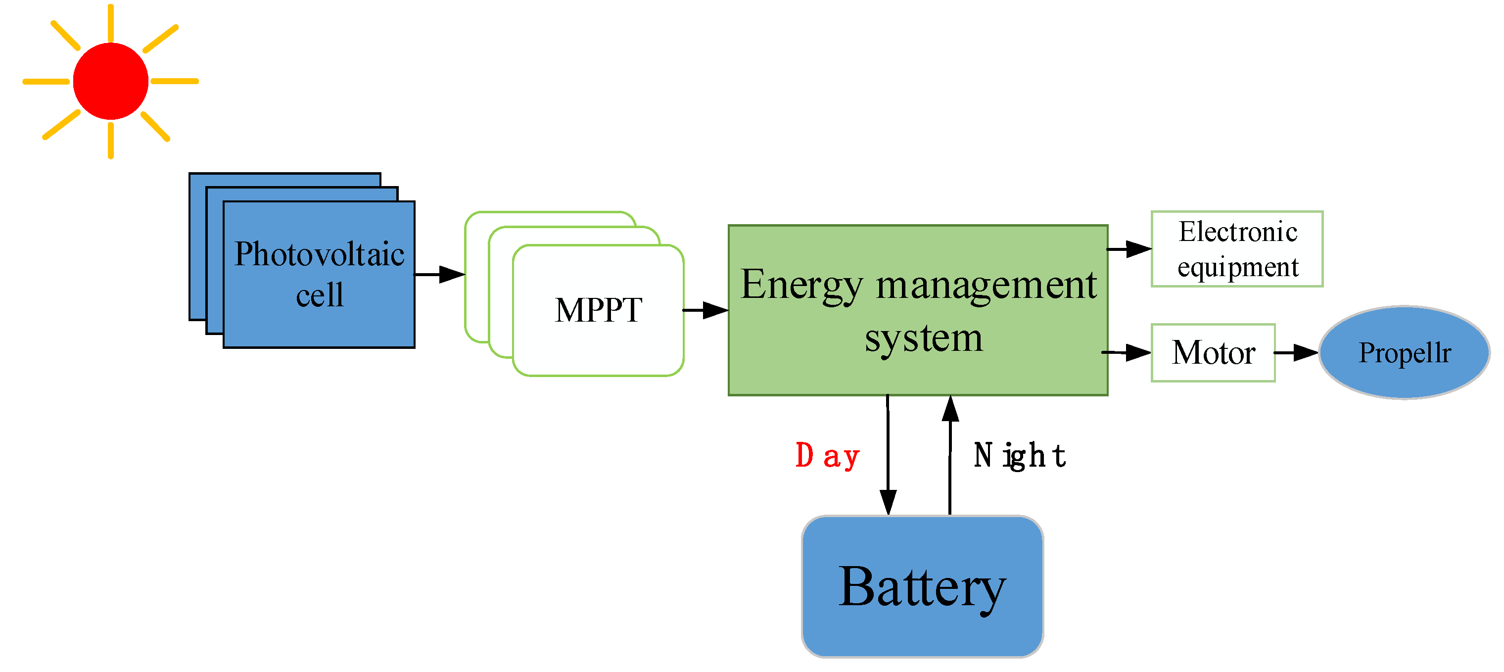
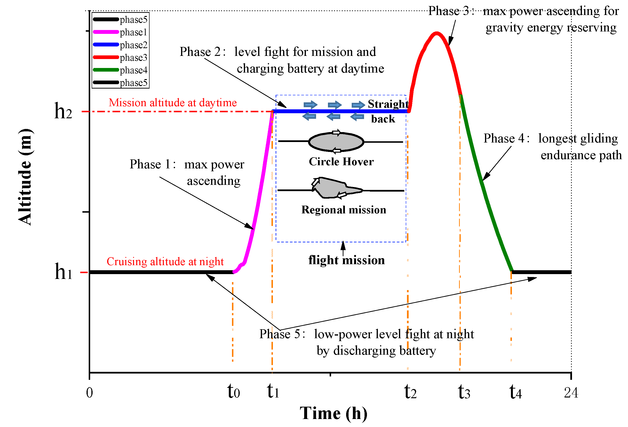
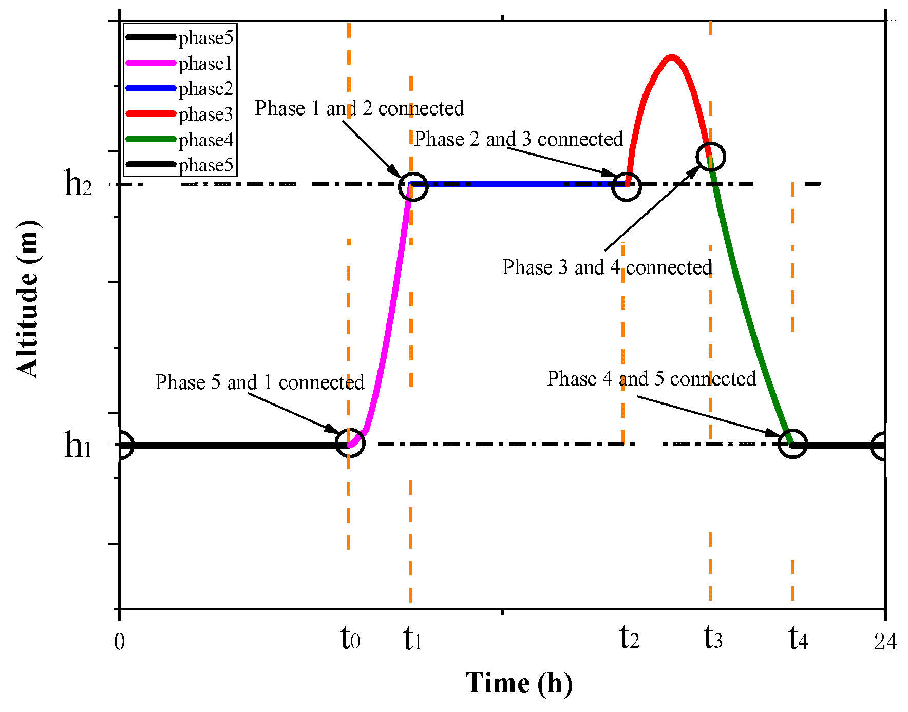
2.1. The Flight Path Phase Model

Based on the gravity energy reserving and mission altitude at daytime for engineering applications, the SPA HALE flight path is divided into five phases, as shown in Figure 2 below. It includes two level flight phases, two ascent phases and a gravity gliding phase. The two level flight phases in this study are defined as cruising altitude at night and mission altitude at daytime, which are marked h 1 and h 2 .
Firstly, the establishment of mission altitude h 2 is beneficial to practical engineering applications, which is more conducive to the smooth charging of the energy storage battery. Besides, the mission altitude also provides possibilities for the SPA to execute a flight mission in a stable process, in which the wind speed is lower. Generally, the flight mission could be straight back, circle hover and ra egional mission for monitoring and communication, as shown in Figure 2. Secondly, as we known, the SPA cruising at the altitude h 1 in night means lower power consumption. Meanwhile, some tasks such as detection can be also completed at this altitude. Therefore, the above-proposed SPA HALE flight path is very suitable for a day-high and night-low flight strategy and engineering task application, which is different from the three-stage gravity energy storage flight strategy. The details of the phases are as follows.
Phase 1: Maximum power ascending
This flight phase starts at time t 0 when the solar radiation energy acquired by the HALE SPA at level flight altitude h 1 is sufficient to support the climb flight. The phase ends at time t 1 when the flight mission altitude h 2 is reached. The flight power supply mode of this phase is: all the solar energy obtained is used for the climbing movement. Therefore, the electric power converted by the energy management system is all available for the aircraft.
Inequality (including greater than or equal to and less than or equal to ) path constraints (IPC), in the optimal control problem usually refers to the constraints of certain functions in a certain path process (“a phase”). Generally speaking, in addition to control variables, time and static parameters are also within the scope of these constraint functions. As a result, the SPA flight power P and the change rate q of the energy storage battery in the Phase 1 are as follows:
{ P = I · S s c η M P P T η m o t η p l r η S C = T · v d Q d t = q = 0
where P is the SPA flight power, q the rate of the battery, T the thrust of propulsion system, v the aircraft speed, Q the battery capacity, S S C the photovoltaic cell area, η M P P T the efficiency of Maximum Power Point Tracking (MPPT) device, η m o t the efficiency of aircraft motor, η p l r the efficiency of aircraft propeller, η S C the efficiency of photovoltaic cell. In addition, the photovoltaic cell area S S C can be obtained by the wing area as follows:
S S C = k W · S W
where S W is the wing area, k W the pavement ratio of photovoltaic cell.
Phase 2: Level flight for mission and charging battery
The phase begins at time t 1 when the predetermined mission altitude h 2 is reached, and ends at time t 2 when the energy storage battery is fully charged. In the process, the SPA flies at the altitude h 2 and charges the energy storage battery. The flight power supply mode of this phase is: part of the electrical energy converted by photovoltaic cells is used to maintain the aircraft’s flight, and the rest is used to charge the energy storage battery. In this phase, the IPC are as follows:
d Q d t = q = ( I · S S C η S C η M P P T P η m o t η p l r ) · η b a t i n
{ d γ d t = 0 d h d t = 0
where I is the solar radiation intensity, η b a t i n the charging efficiency of energy storage battery, γ the aircraft flight path angle, h the aircraft flight altitude.
Phase 3: Maximum power ascending for gravity energy storage
This flight phase starts at time t 2 when the energy storage battery is brimming, and ends at time t 3 when the solar irradiation is zero. This phase includes maximum power climbing and powered gravity gliding and depends on whether the solar radiation intensity can meet the power consumption required for flight at its altitude. Before the solar radiation disappears in this process, the maximum flying altitude that the SPA can reach relies on the obtained solar radiation energy. As a result, the flight phase can make full use of the excess solar energy for gravity energy storage. The flight power supply mode of this phase is: all the electrical energy converted by solar cells is used to power the aircraft. Therefore, the IPC of the aircraft in this phase are the same as phase 1, as follows:
{ P = I · S s c η M P P T η m o t η p l r η S C = T · v d Q d t = q = 0
Phase 4: Longest gliding endurance path
The phase begins at time t 3 when there is no irradiance, and ends at time t 4 when the SPA glides to the cruising altitude h 1 at night. Throughout the whole stage, the SPA reduces altitude by gliding without thrust. The SPA energy system does not provide any electricity to the aircraft during this flight phase. In the phase, the IPC of SPA satisfy:
{ T = 0 d Q d t = q = 0
Phase 5: Low-power level flight by discharging battery at night
This flight phase starts at time t 4 when the SPA reaches the cruising altitude h 1 , and ends at time t 5 when the solar radiation energy acquired by the SPA at altitude h 1 is sufficient to support the climbing flight to the next day phase 1. Basically, t 0 is equal to t 5 . During this stage, the SPA only relies on energy storage batteries for cruising. The power supply mode is: the energy storage battery provides all power consumption during the night. Thence, the IPC of the aircraft are as follows:
d Q d t = q = P η m o t η p l r η b a t o u t
{ d γ d t = 0 d h d t = 0
where η b a t o u t is the discharging efficiency of energy storage battery.

2.2. Aerodynamic Model

Generally, the aerodynamic forces acting on an aircraft can be calculated by the following formula:
{ L = 1 2 ρ v 2 · S W C L D = 1 2 ρ v 2 · S W C D
where L is the lift of aircraft, the D drag force of aircraft, C L and C D are the lift and drag coefficients, ρ is the atmospheric density. In this paper, the ρ value on altitude use the relevant section of the 1976 Standard Atmosphere, as described in reference [25,26].
As we known, the HALE SPA usually has the characteristics of large aspect ratio and its wing are larger than the fuselage. Therefore, C L and C D of this type aircraft are closely related to airfoil profile, angle of attack and Reynolds number. In order to simplified calculation, the C L and C D of SPA can have the following formulas:
{ C L = 0.9 C L 0 C D = C D 0 + C D p + C D i C D i = C L 2 e π A R e = 1.78 ( 1 0.045 A R 0.68 ) 0.64
where C L 0 is the lift coefficient of airfoil, C D 0 , C D p and C D i are the coefficients of the airfoil zero-lift drag, the parasitic drag and the lift-induced drag, e is the Oswald ’s coefficient, A R is the aspect ratio of SPA.
In this study, the Zephyr 7 is the research object. Hence, the airfoil coefficient of aerodynamic characteristic refers to FX 63-137, 13.7% smoothed, Re = 20000 and the parasitic resistance coefficient C D p is 0.005. The detailed data is shown in the Table 1.

2.3. Aircraft Kinematic Model in Three Dimensional

For the research of flight strategy optimization, the focus of SPA during the flight is on the macroscopic characteristics of the trajectory. Therefore, a simplified particle model can be used for research [16]. As shown in Figure 3, the three-dimensional dynamic equation of SPA can be expressed as follows:
{ d v d t = T m D m g · sin γ d γ d t = L m v cos ψ g v cos γ d φ d t = L m v cos γ sin ψ d x d t = v cos γ cos φ d y d t = v cos γ sin φ d h d t = v sin γ
where x , y and h are the SPA position coordinates in flat earth-fixed frame, m the total mass of SPA, g the acceleration of gravity, ψ the aircraft roll angle, φ the aircraft yaw angle.

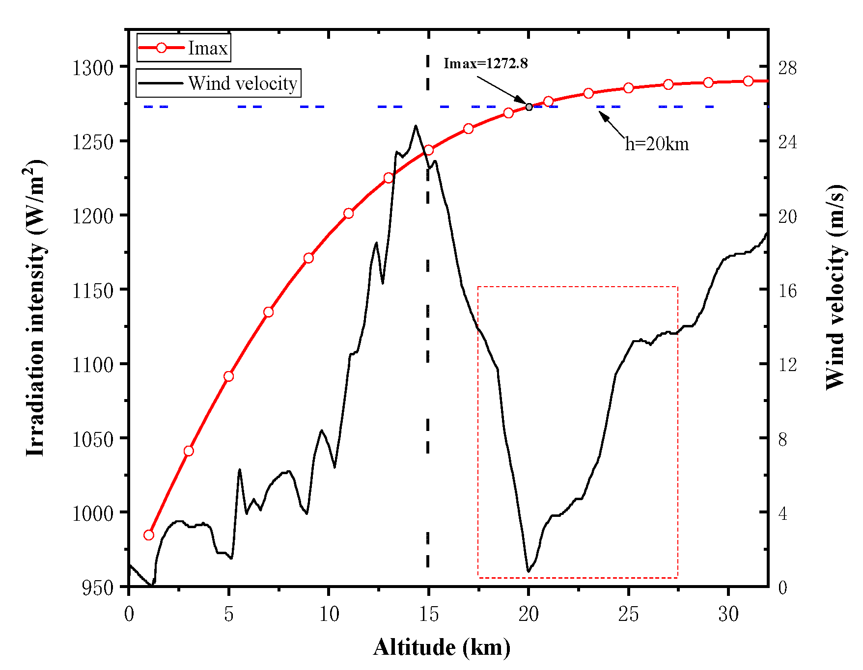
2.4. Solar Irradiation Model and Mission Conditions

During the flight, with the change of flight altitude and attitude, the intensity of solar radiation received by photovoltaic cells on the wing surface of the aircraft will change accordingly. As the main power source of SPA, the amount of solar energy obtained will directly affect its flight performance. Therefore, a relatively accurate solar flux model needs to be established to calculate the energy collection for SPA. In this study, based on the solar radiation intensity calculation model in the earth-fixed frame, the integration of coordinate conversion principle and the flight attitude angle is used to obtain the solar radiation intensity for SPA in the body coordinate system. The details are as follows.

2.4.1. Calculation Model of Solar Radiation Intensity in Ground Coordinate System

This paper defines the earth-fixed frame as O g X g Y g Z g , where O g X g , O g Y g , O g Z g are expressed out the north, west, and vertical upward through the ground, as illustrated in Figure 3. Then in the earth-fixed frame, the solar radiation intensities I X g , I Y g , and I Z g (positive and negative represent directions) in each direction are the following formulas:
{ I X g = I S C · ξ 0 · P C O · cos H S · cos A S I Y g = I S C · ξ 0 · P C O · cos H S · sin A S I Z g = I S C · ξ 0 · P C O · sin H S
where I S C is the solar irradiance constant 1367 W/m2, ξ 0 the eccentricity correction coefficient related to the distance between the sun and the earth, P C O the atmospheric transparency coefficient, H S the sun altitude angle, A S the sun azimuth. Those parameters can be calculated by the formulas in literature [27,28], which are not be described in detail here.

2.4.2. Calculation Model of Solar Radiation Intensity in the Body Coordinate System

This paper defines the aircraft body-fixed frame as O b X b Y b Z b , where O b X b is located in the symmetry of the aircraft and points forward parallel to the fuselage axis, O b Y b points to the left perpendicular to the symmetry plane, O b Z b is expressed out to point upwards and perpendicular to O b X b and O b Y b , as shown in Figure 3. Therefore, the solar radiation intensities I X b , I Y b , and I Z b received in aircraft body-fixed frame can be obtained by the attitude angle (yaw angle φ , pitch angle γ , roll angle ψ ) through coordinate transformation, as shown in Equation (12):
[ I X b I Y b I Z b ] = [ cos γ cos φ cos γ sin φ sin γ sin γ sin ψ cos φ cos ψ sin φ sin γ sin ψ sin φ + cos ψ cos φ sin ψ cos γ sin γ cos ψ cos φ + sin ψ sin φ sin ψ cos φ sin γ cos ψ sin φ cos ψ cos γ ] [ I X g I Y g I Z g ]
Consequently, a solar irradiation model is established in a MATLAB file for later model integration, which can calculate solar radiation intensity with the altitude, date, longitude, latitude, moment, roll angle, pitch angle and yaw angle.

2.5. Problem Optimization Frame

Obviously, the goal of three-dimensional flight strategy optimization for the HALE SPA based on gravity energy reserving and mission altitude is a multi-phase optimization problem, and can be disguised as a nonlinear programming problem. Figure 4 shows the connection of this multi-phase optimization problem. Therefore, the optimization objective, boundary conditions and dynamic equations for each segment need to be analyzed.
The boundary conditions and the optimization objective of HALE SPA for each phase are summarized as bellows:
Phase 1: Maximum power ascending( t 0 - t 1 )
As described in Section 2.1, the main task of the aircraft at this phase is to climb to the mission altitude with the maximum available power, so the performance indicators of the aircraft can be set as follows:
M i n   J 1 = t 1 t 0
The three-dimensional dynamic equation of SPA can be expressed as same as Equation (9), and the applied boundary conditions can be as follows:
{ v { 1 } ( t 0 ) = v 0 γ { 1 } ( t f ) = 0 φ { 1 } ( t 0 ) = φ 0 h { 1 } ( t f ) = h 2 γ { 1 } ( t 0 ) = 0 Q { 1 } ( t f ) = Q min x { 1 } ( t 0 ) = x 0 y { 1 } ( t 0 ) = y 0 h { 1 } ( t 0 ) = h 1 Q { 1 } ( t 0 ) = Q min
Phase 2: Level flight for mission and charging battery( t 1 - t 2 )
The aim of phase 2 is the task execution in predetermined mission altitude as well as charge battery, so the power consumption of the level flight is concerned at this phase. Hence, the target optimization function can be expressed as per the following formula:
M i n   J 2 = t 2 t 1 P l e v e l d t = t 2 t 1 T h 2 v d t
The applied boundary conditions satisfy:
{ v { 2 } ( t 0 ) = v { 1 } ( t f ) γ { 2 } ( t f ) = 0 φ { 2 } ( t 0 ) = φ { 1 } ( t f ) h { 2 } ( t f ) = h 2 γ { 2 } ( t 0 ) = γ { 1 } ( t f ) = 0 Q { 2 } ( t f ) = Q max x { 2 } ( t 0 ) = x { 1 } ( t f ) y { 2 } ( t 0 ) = y { 1 } ( t f ) h { 2 } ( t 0 ) = h { 1 } ( t f ) = h 2 Q { 2 } ( t 0 ) = Q min
Phase 3: Maximum power ascending for gravity energy storage( t 2 - t 3 )
In the phase 3, the final altitude is the key to the optimization. The higher altitude the SPA gains, the greater advantage for the phase 4. Therefore, the performance indicators can be set as follows:
M a x   J 3 = h { 3 } ( t f )
The applied boundary conditions in this phase can be expressed as follows:
{ v { 3 } ( t 0 ) = v { 2 } ( t f ) φ { 3 } ( t 0 ) = φ { 2 } ( t f ) h { 3 } ( t f ) h 2 γ { 3 } ( t 0 ) = γ { 2 } ( t f ) = 0 Q { 3 } ( t f ) = Q max x { 3 } ( t 0 ) = x { 2 } ( t f ) y { 3 } ( t 0 ) = y { 2 } ( t f ) h { 3 } ( t 0 ) = h { 2 } ( t f ) = h 2 Q { 3 } ( t 0 ) = Q max
Phase 4: Longest gliding endurance path( t 3 - t 4 )
The aim of the aircraft at this phase is to achieve gliding for longer time, which is helpful for delaying the moment of battery discharge and the night flight for SPA. Hence, the target optimization function can be expressed as follow:
M a x   J 4 = t 4 t 3
The applied boundary conditions in phase 4 satisfy:
{ v { 4 } ( t 0 ) = v { 3 } ( t f ) γ { 4 } ( t f ) = 0 φ { 4 } ( t 0 ) = φ { 3 } ( t f ) h { 4 } ( t f ) = h 1 γ { 4 } ( t 0 ) = γ { 3 } ( t f ) Q { 4 } ( t f ) = Q max x { 4 } ( t 0 ) = x { 3 } ( t f ) y { 4 } ( t 0 ) = y { 3 } ( t f ) h { 4 } ( t 0 ) = h { 4 } ( t f ) Q { 4 } ( t 0 ) = Q max
Phase 5: Low-power level flight by discharging battery at night( t 4 - t 5 )
The aim for this phase is to keep the SPA aloft in the cruising altitude h 1 with minimum power consumed. Hence, the performance indicators can be expressed as per the following formula:
M i n   J 5 = t 5 t 4 P l e v e l d t = t 5 t 4 T h 1 v d t
The applied boundary conditions in this phase satisfy:
{ v { 5 } ( t 0 ) = v { 4 } ( t f ) γ { 5 } ( t f ) = 0 φ { 5 } ( t 0 ) = φ { 4 } ( t f ) h { 5 } ( t f ) = h 1 γ { 5 } ( t 0 ) = γ { 4 } ( t f ) = 0 Q { 5 } ( t f ) = Q min x { 5 } ( t 0 ) = x { 4 } ( t f ) y { 5 } ( t 0 ) = y { 4 } ( t f ) h { 5 } ( t 0 ) = h { 4 } ( t f ) = h 1 Q { 5 } ( t 0 ) = Q max
To summarize, the total target optimization function can be expressed as follow:
M i n   J = J 1 + J 2 J 3 J 4 + J 5 = ( t 0 + t 1 + t 3 t 4 ) + t 1 t 2 P l e v e l d t + t 5 t 4 P l e v e l d t h { 3 } ( t f )
In addition, the day and night cycle boundary conditions also satisfy the following formulas in order that the HALE SPA can perform monthly flight mission.
{ v { 5 } ( t f ) = v { 1 } ( t 0 ) φ { 5 } ( t f ) = φ { 1 } ( t 0 ) γ { 5 } ( t f ) = γ { 1 } ( t 0 ) x { 5 } ( t f ) = x { 1 } ( t 0 ) y { 5 } ( t f ) = y { 1 } ( t 0 ) h { 5 } ( t f ) = h { 1 } ( t 0 ) Q { 5 } ( t f ) = Q max t 5 t 0 = 24   hours

2.6. Optimization Approach and Solving Process

Generally speaking, the trajectory optimization problem can be transformed into a nonlinear numerical optimal solution process by establishing a mathematical model. Some of the original conditions can be transformed into corresponding states and control constraints after transformation. The GPM is a direct global method, which has advantages in calculation efficiency and accuracy. Therefore, the GPM is use to solving this multi-phase optimization problem in this paper and the above optimization control problem can be disguised as a nonlinear programming problem. The basic idea of GPM is the polynomial interpolation of state and control variables in the whole time region [29] so that the continuous optimal control problem can be formally transformed. Hence, the problem is cleverly to become a traditional solution to solve process of nonlinear algebraic equations constrained by IPC, and the GPM solution steps are roughly as follows:
Firstly, the time domain transformation for each phase is modified to transform the time period t n [ t 0 n t f n ] into time interval τ n [ 1 , 1 ] . Assuming that there are M numbers LG allocation points on each interval τ n [ 1 , 1 ] , and then those distribution points can be characterized as characteristic roots of Legendre polynomials in M numbers order [30]. As result, the state and control variables can be approximation by M + 1 order Legendre polynomials. Hence, the dynamic constraint equations can be converted to algebraic constraint equations by the above-approximation. Meanwhile, the boundary constraints also can be transcribed by τ n k , which is the k numbers of the LG points. At the same time, because the performance indicator function does not contain state variables, the total target optimization function still can be expressed by Equation (24).
In summary, the original multi-phase continuous optimization problem for SPA can be transformed into nonlinear programming problem, which is defined by target optimization function in Equation (23) and dynamic constraints in above-mentioned. Besides, the optimization parameters can be obtained by a MATLAB software named Gauss pseudo-spectral Optimization Software (GPOPS) [31] with some reasonable optimality and feasibility tolerances.
In this study, the angle of attack α , the roll angel ψ and the thrust T are chosen as three control variable to change the attitude and flight altitude of the SPA. The paper combines the GPOPS and function files of other models in Section 2 to solve the nonlinear programming problem for SPA in MATLAB. The optimization solving process is shown as follows.
Step 1: Initialize the SPA parameters, geographical parameters and mission parameters.
Step 2: Define the state and control variables and set up the limits on variables.
Step 3: Provide boundary and initial values in each phase of the problem, and set up the event constraints which is linked in phases.
Step 4: Provide an initial Mesh for each phase, the phase number is 5 and the LG allocation points number is 40 for each phase in this study.
Step 5: Assemble all information into setup structure, which contains the aircraft kinematic model, aerodynamic model, solar irradiation and day-night cycle boundary conditions, etc., function files.
Step 6: Load the target optimization function and the variable battery mass m b a t of SPA for satisfying the t 5 t 0 = 24 h .m function files;
Step 7: Solve the problem by using GPOPS in MATLAB;
Step 8: Summarize the information of each node and phase to obtain the optimal flight trajectory for SPA base on energy reserving and mission altitude.

3. Simulation and Results Discussion

3.1. Simulation Condition

Firstly, the study has tried to analyze the environmental characteristics of the flight area by the above model in Section 2.4 for further parameter settings. Figure 5 display the variation of the maximum solar irradiance intensity with altitude in the south china sea (105°E, 4°N, data = 266). Besides, a realistic wind speed data as a function of the altitude from high altitude detection balloon is also been shown. It can be concluded from the analysis that the maximum solar irradiance intensity will not change drastically with the altitude after reaching 20 km. Meanwhile, the wind speed in the environment from 17.5 km to 27.5 km is relatively low, which is beneficial to mission execution.
After the above preparation works, a series of numerical simulations are computed to verify the proposed method. It will be very efficient to solve the flight trajectory optimization problem into a nonlinear programming problem. The parameters of initial configuration are listed in Table 2, which is referred from Zephyr 7 [2,4,8], as the Zephyr 7 is been introduced comprehensive and detailed in all the literatures among the high-altitude SPA. In addition, the accurate parameters of Zephyr 7 is more conducive to the advantage and reliability of the simulation results by this strategy.
The set of simulation conditions and constraints of variables are listed in Table 3 and Table 4, respectively.

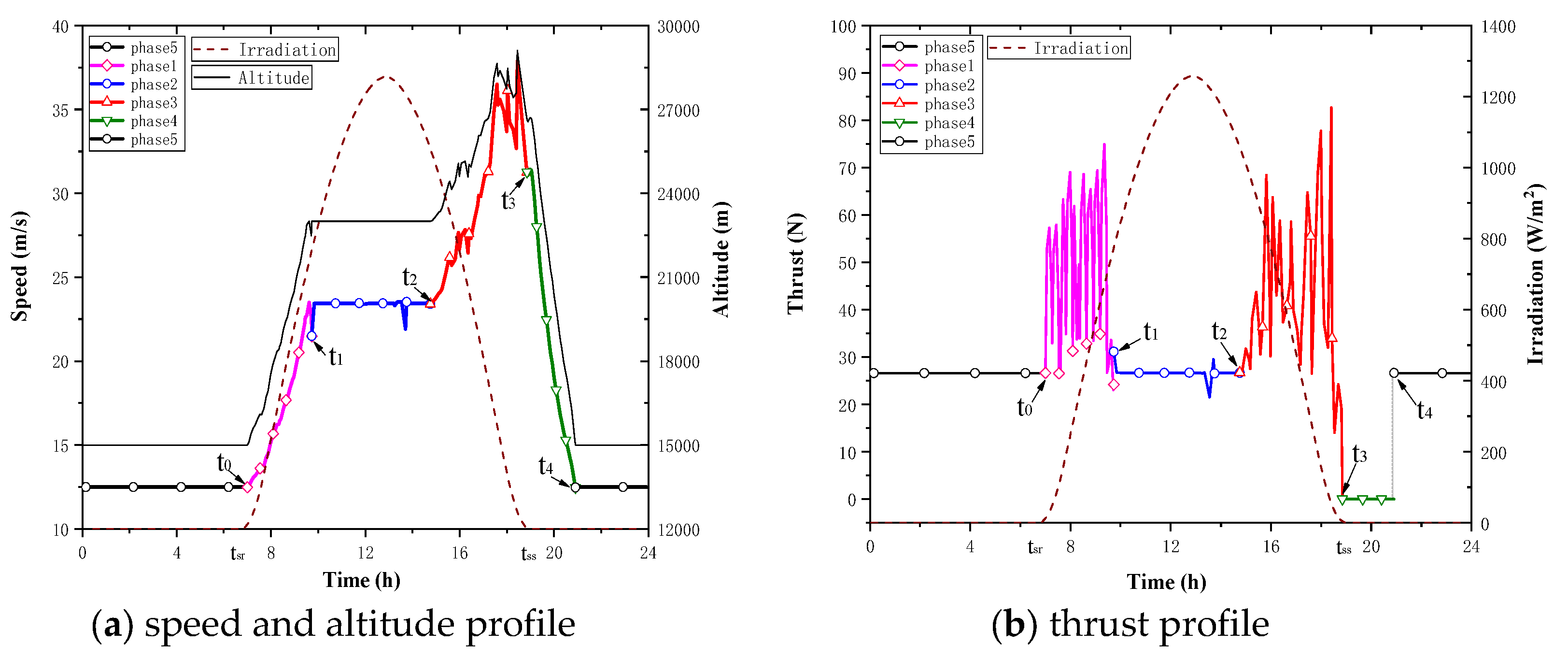
3.2. Result and Discussion

In this study, the SPA selects the South China Sea (105°E-116°E, 4°N-15°N) as the target flight area. Besides, the two level flight altitude are 15km and 23km, which is obtained according to the environmental characteristics of the flight area. As described in Section 2.6 above, the study firstly use the GPM method to solve the optimal flight path, and then look for the minimum battery mass that meets long flight time constraints. As results, the final optimized battery mass m b a t of Zephyr 7 for satisfying the t 5 t 0 = 24 h in Equation (25) is 12.61 kg, which is shown in MATLAB workspace. Compared with the original initial parameter of battery mass, it is equivalent to a 23.1% reduction for Zephyr 7. It also means how much potential energy can be gained by this flight strategy. Meanwhile, The the three-dimensional trajectory optimization, the speed with altitude, the quantity of electricity, the thrust, the flight path pitch angle with attack angle, the yaw angle and the roll angle with minimal battery mass are shown in Figure 6, Figure 7, Figure 8, Figure 9 and Figure 10, respectively.
From the Figure 7a, the time of each phase for this flight strategy is 2.73 h, 5.03 h, 4.09 h, 2.06 h and 10.09 h, respectively. Meanwhile, the speed has good following to the altitude, and the highest flight altitude of Zephyr 7 can reach is about 28.47km at time 18:03. In addition, it can be seen that the flight trajectory of phase 2 from Figure 6 is estimated to have a symmetrical trend at noon time as the same as the trend of yaw angle in Figure 10, which can conclude that the SPA will adjust the trajectory with the solar altitude angle changing symmetrically at the standard noon time. Besides, in order to better analyze the changes of battery charge percentage at noontime, we have performed a simple polynomial interpolation on the data points of the battery percentage at 11:00 to 14:00 by EXCEL. As shown in Figure 8, the battery charge rate has the same trend to the intensity of solar radiation, which is different from the same charge rate in some other studies. More importantly, the unpowered gliding time of the phase 4 is 2.06 h (Figure 8), which did not consume the energy of the battery. This optimization result can be seen as the result of gravity energy reserving, and thus the quality of the battery can be reduced by this strategy.
Another thing has to note is that there is a phenomenon of oscillation at the connection points over the flight time. The literature [32] has specifically studied the oscillation of this numerical result, and the research results show that the calculation results of GPM are stable. Besides, the calculation results of the literature [33] also indicate that the optimal gravity glide track has the characteristics of oscillating with time by GPM. Therefore, the calculation results are reasonable and credible in this paper.

4. Conclusions

In this paper, research on HALE flight trajectory with minimal battery mass for SPA based on gravity energy reserving and mission altitude is conduced to achieve the following.
  • A flight path phase model based on gravity energy reserving and mission altitude has been carried out for analysis and research background for engineering applications is taken into consideration for the day and night cycle flight and tasks.
  • GPM is feasible for the research on flight trajectory optimization for high-altitude SPA due to its advantages in calculation efficiency and accuracy as well as the integration between GPOPS and function files in MATLAB.
  • This flight trajectory optimization results shows that Zephyr 7 can reduce the battery mass from 16 kg to 12.61 kg for the day and night cycle flight and missions, which equals to reducing its total mass by 6.4%.
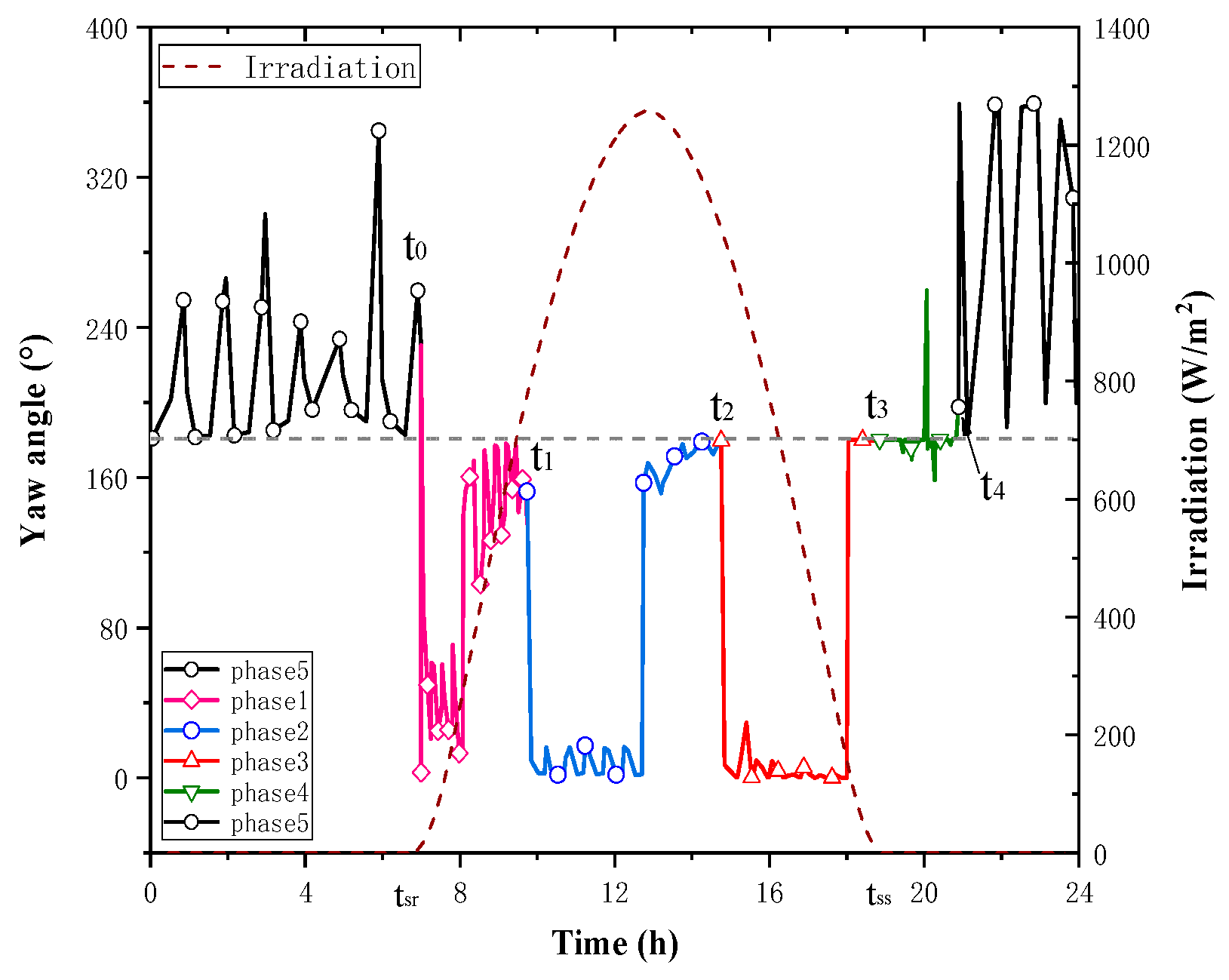
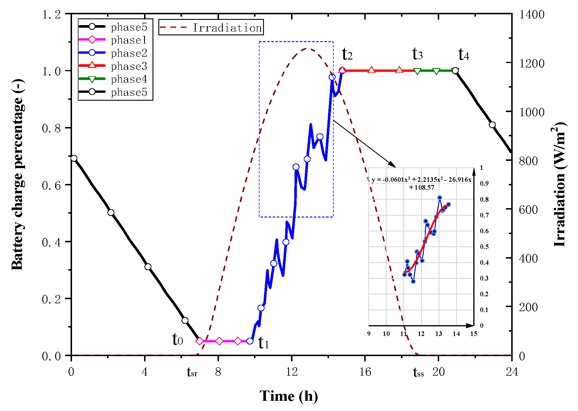
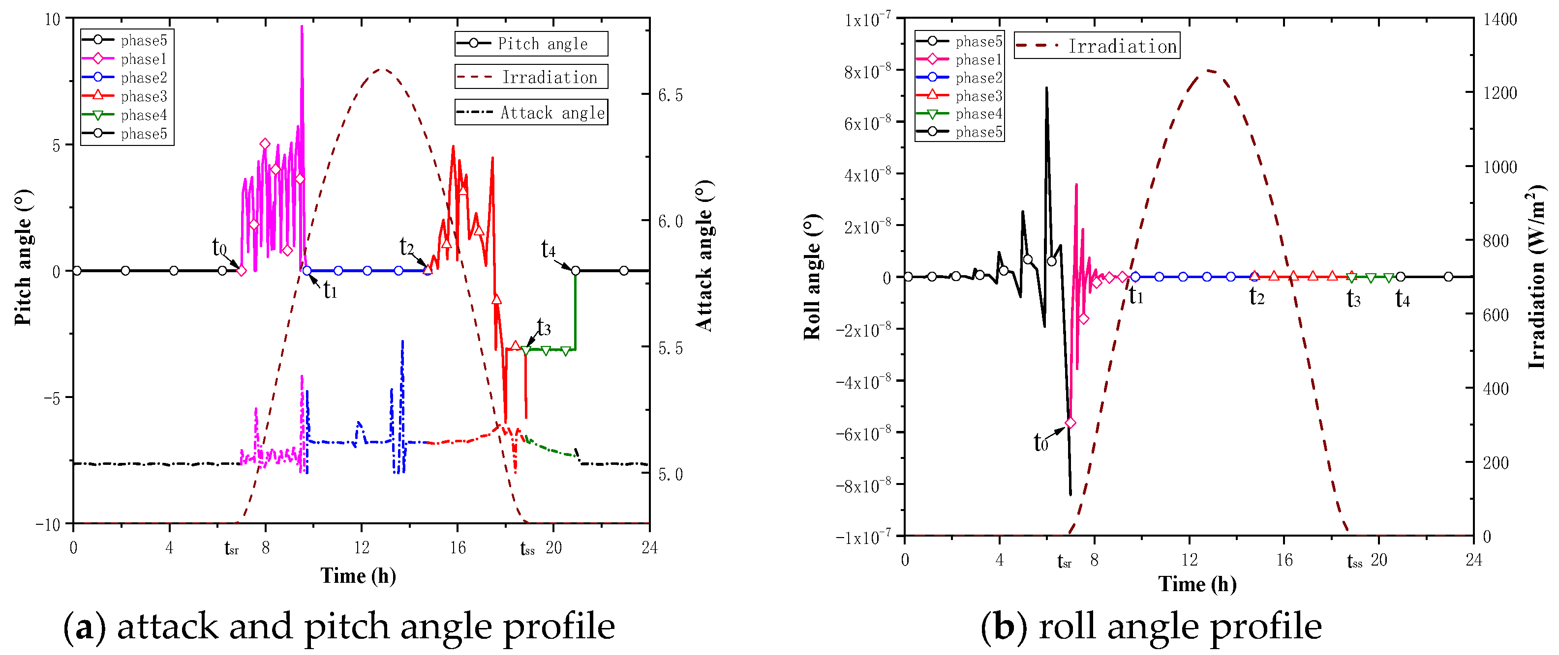
  • According the optimization results, the yaw angel may have more influence on high-altitude SPA 3D flight strategy in energy harvesting than the roll angle and the battery charge rate has good following to the solar irradiation intensity, which is instructive for SPA to use solar radiation reasonably at noon phase in mission execution.
This study focuses on flight strategy optimization of the HALE SPA in three-dimensional, and gives the optimal flight trajectory with minimal battery mass based on gravity energy reserving and mission altitude. It will be very interesting to have the result of anther case in different simulation conditions based on this flight strategy. As a result for the future works, there are two aspects of the related work. Firstly, we will further design mission path planning frame-work for the mission altitude in the integrated model, which is more complicated than the proposed framework. Secondly, the energy management for this flight strategy and the influences of other environmental factors for SPA such as the wind will also be taken into our considerations in future research.

Author Contributions

“Conceptualization, M.S. and K.S.; methodology, M.S.; software, M.S.; validation, M.S., X.J. and K.S.; formal analysis, K.S.; investigation, M.Z.; resources, K.S.; data curation, M.S.; writing—original draft preparation, M.S.; writing—review and editing, M.S.; visualization, K.S.; supervision, K.S.; project administration, M.Z.; funding acquisition, K.S. All authors have read and agreed to the published version of the manuscript.

Funding

This work was supported by the National Natural Science Foundation of China under Grant No. 51775021, Key Laboratory of Aircraft Advanced Design Technology (Beihang University) Ministry of industry.

Conflicts of Interest

The authors declare no conflict of interest.

References

  1. Noth, A. Design of Solar Powered Airplanes for Continuous Flight. Ph.D. Thesis, ETH Zurich, Zurich, Switzerland, 2008. [Google Scholar]
  2. Gao, X.Z. Research on High-Altitude Long-Endurance Flight based on Energy Storage by Gravitational Potential and Energy Extraction from Wind Shear. Ph.D. Thesis, National University of Defense Technology, Changsha, China, 2014. [Google Scholar]
  3. Noll, T.E.; Brown, J.M.; Perez-Davis, M.E.; Ishmael, S.D.; Tiffany, G.C.; Gaier, M. Investigation of the Helios Protype Aircraft Mishap; Volume I Mishap Reprot: Hamptom, VA, USA, 2004. [Google Scholar]
  4. Zephyr Pioneering the Stratosphere. Available online: www.airbus.com (accessed on 7 August 2018).
  5. Hannes, R. Fly Around the World with a Solar Powered Airplane. In Proceedings of the 26th Congress of international Council of the Aeronautical Sciences, Anchorage, Alaska, 14–19 September 2008. [Google Scholar]
  6. Klesh, A.T.; Kabamba, P.T. Solar-Powered Aircraft: Energy-Optimal Path Planning and Perpetual Endurance. J. Guid. Control. Dyn. 2009, 32, 1320–1329. [Google Scholar] [CrossRef] [Green Version]
  7. Rajendran, P.; Masral, M.H.; Kutty, H.A. Perpetual Solar-Powered Flight across Regions around the World for a Year-Long Operation. Aerospace 2017, 4, 20. [Google Scholar] [CrossRef] [Green Version]
  8. Zhu, X.F. Generalized Energy Based Conceptual Design Method of Solar-powered Airplane. Ph.D. Thesis, National University of Defense Technology, Changsha, China, 2014. [Google Scholar]
  9. Huang, Y.; Chen, J.; Wang, H.; Su, G.; Yu, H.; Jianguo, C.; Honglun, W.; Guofeng, S. A method of 3D path planning for solar-powered UAV with fixed target and solar tracking. Aerosp. Sci. Technol. 2019, 92, 831–838. [Google Scholar] [CrossRef]
  10. Ding, Y.; Zhou, Z.; Wang, Z.; Liu, H.; Wang, K. Bionic Stiffener Layout Optimization with a Flexible Plate in Solar-Powered UAV Surface Structure Design. Appl. Sci. 2019, 9, 5196. [Google Scholar] [CrossRef] [Green Version]
  11. Klesh, A.; Kabamba, P. Energy-Optimal Path Planning for Solar-Powered Aircraft in Level Flight. In Proceedings of the Guidance Navigation, and Control Conference, Hilton, SC, USA, 20–23 August 2007. [Google Scholar]
  12. Gao, X.-Z.; Hou, Z.-X.; Guo, Z.; Fan, R.-F.; Chen, X.-Q. The equivalence of gravitational potential and rechargeable battery for high-altitude long-endurance solar-powered aircraft on energy storage. Energy Convers. Manag. 2013, 76, 986–995. [Google Scholar] [CrossRef]
  13. Widmer, J.D.; Donaghy-Spargo, C.; Atkinson, G.J.; Mecrow, B.C. Solar Plane Propulsion Motors With Precompressed Aluminum Stator Windings. IEEE Trans. Energy Convers. 2014, 29, 681–688. [Google Scholar] [CrossRef] [Green Version]
  14. Noth, A. Designing solar airplanes for continuous flight. SPIE Newsroom 2009. [Google Scholar] [CrossRef] [Green Version]
  15. Brandt, S.A.; Gilliam, F.T. Design analysis methodology for solar-powered aircraft. J. Aircr. 1995, 32, 703–709. [Google Scholar] [CrossRef]
  16. Sachs, G.; Lenz, J.; Holzapfel, F. Unlimited Endurance Performance of Solar UAVs with Minimal or Zero Electrical Energy Storage. In Proceedings of the AIAA Guidance Navigation, and Control Conference, Chicago, IL, USA, 10–13 August 2009. [Google Scholar]
  17. Langelaan, J.W.; Roy, N. Enabling New Missions for Robotic Aircraft. Science 2009, 326, 1642–1644. [Google Scholar] [CrossRef]
  18. Langelaan, J.W.; Spletzer, J.; Montella, C.; Grenestedt, J. Wind Field Estimation for Autonomous Dynamic Soaring. In Proceedings of the 2012 IEEE International Conference on Robotics and Automation, Chengdu, China, 5–8 August 2012; pp. 16–22. [Google Scholar]
  19. Zhong, G.X.; Xi, H.Z.; Xia, L.J.; Qian, C.X.; Zheng, G. The influence of wind shear to the performance of high-altitude solar-powered aircraft. Proc. Inst. Mech. Eng. Part G: J. Aerosp. Eng. 2013, 228, 1562–1573. [Google Scholar] [CrossRef]
  20. Spangelo, S.; Gilbert, E.; Klesh, A.; Kabamba, P.; Girard, A. Periodic Energy-Optimal Path Planning for Solar-Powered Aircraft. In Proceedings of the AIAA Guidance Navigation, and Control Conference, Chicago, IL, USA, 10–13 August 2009. [Google Scholar]
  21. Hosseini, S.; Mesbahi, M. Energy-Aware Aerial Surveillance for a Long-Endurance Solar-Powered Unmanned Aerial Vehicles. J. Guid. Control. Dyn. 2016, 39, 1–14. [Google Scholar] [CrossRef]
  22. Martin, R.A.; Gates, N.S.; Ning, A.; Hedengren, J.D. Dynamic Optimization of High-Altitude Long-Endurance Aircraft Trajectories Under Station-Keeping Constraints. J. Guid. Control Dyn. 2019, 42, 538–552. [Google Scholar] [CrossRef] [Green Version]
  23. Wang, S.Q.; Ma, D.L.; Yang, M.Q.; Zhang, L.; Li, G.X. Flight strategy optimization of high-altitude long-endurance solar-powered aircraft based on Gauss pseudo-spectral method. Chin. J. Aeronaut. 2019. [Google Scholar] [CrossRef]
  24. Gao, X.-Z.; Hou, Z.-X.; Guo, Z.; Chen, X.-Q.; Chen, X.-Q. Joint optimization of battery mass and flight trajectory for high-altitude solar-powered aircraft. Proc. Inst. Mech. Eng. Part G: J. Aerosp. Eng. 2014, 228, 2439–2451. [Google Scholar] [CrossRef]
  25. Minzner, R.A. The 1976 Standard Atmosphere and its relationship to earlier standards. Rev. Geophys. 1977, 15, 375. [Google Scholar] [CrossRef]
  26. A Sample Atmosphere Table(US Units). Available online: http://www.pdas.com/atmosTable2US.html (accessed on 9 July 2017).
  27. Reda, I.; Andreas, A. Solar position algorithm for solar radiation applications. Sol. Energy 2004, 76, 577–589. [Google Scholar] [CrossRef]
  28. Aslam, M.; Lee, J.-M.; Kim, H.-S.; Lee, S.-J.; Hong, S. Deep Learning Models for Long-Term Solar Radiation Forecasting Considering Microgrid Installation: A Comparative Study. Energies 2019, 13, 147. [Google Scholar] [CrossRef] [Green Version]
  29. Cao, X.Q. Optimal control for a chaotic system by means of Gauss pseudospectral method. Acta Phys. Sin. 2013, 62, 1–6. [Google Scholar]
  30. Hosseini, M.M. A modified pseudospctral methods for numerical solution of ordinary differential equations systems. Appl. Math. Comput. 2006, 176, 470–475. [Google Scholar]
  31. Michael, A.P.; Rao, A.V. GPOPS-2: A MATLAB Software for Solving Multiple-Phase Optimal Control Problems Using hp-Adaptive Gaussian Quadrature Collocation Methods and Sparse Nonlinear Programming. ACM Trans. Math. Softw. 2014, 41, 1–33. [Google Scholar]
  32. Sun, Y.; Zhang, M. Optimal reentry range trajectory of hypersonic vehicle by Gauss Pseudospectral Method. In Proceedings of the 2011 2nd International Conference on Intelligent Control and Information Processing, Guilin, China, 25–28 July 2011; Volume 1, pp. 545–549. [Google Scholar]
  33. Gao, X.-Z.; Hou, Z.-X.; Guo, Z.; Wang, P.; Zhang, J.-T. Research on characteristics of gravitational gliding for high-altitude solar-powered unmanned aerial vehicles. Proc. Inst. Mech. Eng. Part G: J. Aerosp. Eng. 2012, 227, 1911–1923. [Google Scholar] [CrossRef]
Figure 1. Schematic diagram of energy system for SPA.
Applsci 10 02243 g001
Figure 2. Scheme flight path phase map based on gravity energy storage and mission altitude.
Applsci 10 02243 g002
Figure 3. Schematic diagram of earth-fixed frame and aircraft body-fixed frame.
Applsci 10 02243 g003
Figure 4. Schematic diagram of connection for multi-phase optimization problems.
Applsci 10 02243 g004
Figure 5. Variations of maximum solar irradiance and wind velocity with altitude.
Applsci 10 02243 g005
Figure 6. Optimal three dimensional flight trajectory with minimal battery mass based on gravity energy reserving and mission altitude.
Applsci 10 02243 g006
Figure 7. Optimal speed and altitude and thrust profile with minimal battery mass.
Applsci 10 02243 g007
Figure 8. Optimal battery charge percentage profile with minimal battery mass.
Applsci 10 02243 g008
Figure 9. Optimal yaw angle profile with minimal battery mass.
Applsci 10 02243 g009
Figure 10. Optimal attack angle and attitude angle profile with minimal battery mass.
Applsci 10 02243 g010
Table 1. The airfoil coefficient of lift and drag.
α (°)−6−5−4−3−2−10123
C L 0 0.07890.2260.38150.53430.64640.75960.87630.99061.09711.2013
C D 0 0.03440.02040.01620.01320.0140.01450.01460.01480.01490.0152
α (°)45678910111213
C L 0 1.30391.39611.47211.56441.63091.67071.68531.67251.66591.6776
C D 0 0.01560.0160.01620.01770.01960.02240.02720.03570.04630.0569
Table 2. The parameters of initial configuration for model.
ParameterValueDescription
m s t r u c t (kg)37Mass of structure
m b a t (kg)16Battery mass
E b a t (Wh/kg)350Energy density of battery
b (m)22.5Span length
S W (m2)25.3Wing area
S S C (m2)20.24Area of photovoltaic cells
η S C (-)0.2efficiency of photovoltaic cell
η M P P T (-)0.9Efficiency of MPPT
η m o t (-)0.85efficiency of aircraft motor
η p l r (-)0.8efficiency of aircraft propeller
η b a t i n (-)0.9Efficiency of battery for charging
η b a t o u t (-)0.9Efficiency of battery for discharging
Table 3. The parameters of simulation conditions.
ParameterValueDescription
h 1 (km)15Cruising altitude
h 2 (km)23Battery mass
SOC 0 0.05Initial battery percentage
d n (-)266Autumn equinox day number
Lati (°)4Latitude of the starting point
Long (°)105Longitude of starting point
t s r (h)6.8611The sunrise time
t n o o n (h)12.8564The standard noon time
t s s (h)18.8517The sunset time
Table 4. The constraints of variables.
ParameterMinimum ValueMaximum Value
h (km)1530
v (m/s)050
S O C 0 0.050.99
L a t i (°)415
L o n g (°)10511
α (°)510
γ (°)-1515
ψ (°)-11
T (N)01000

