A Corrected Adaptive Balancing Approach of Motorized Spindle Considering Air Gap Unbalance


Abstract
Featured Application
Abstract
1. Introduction
2. Unbalance and Force of Motorized Spindle
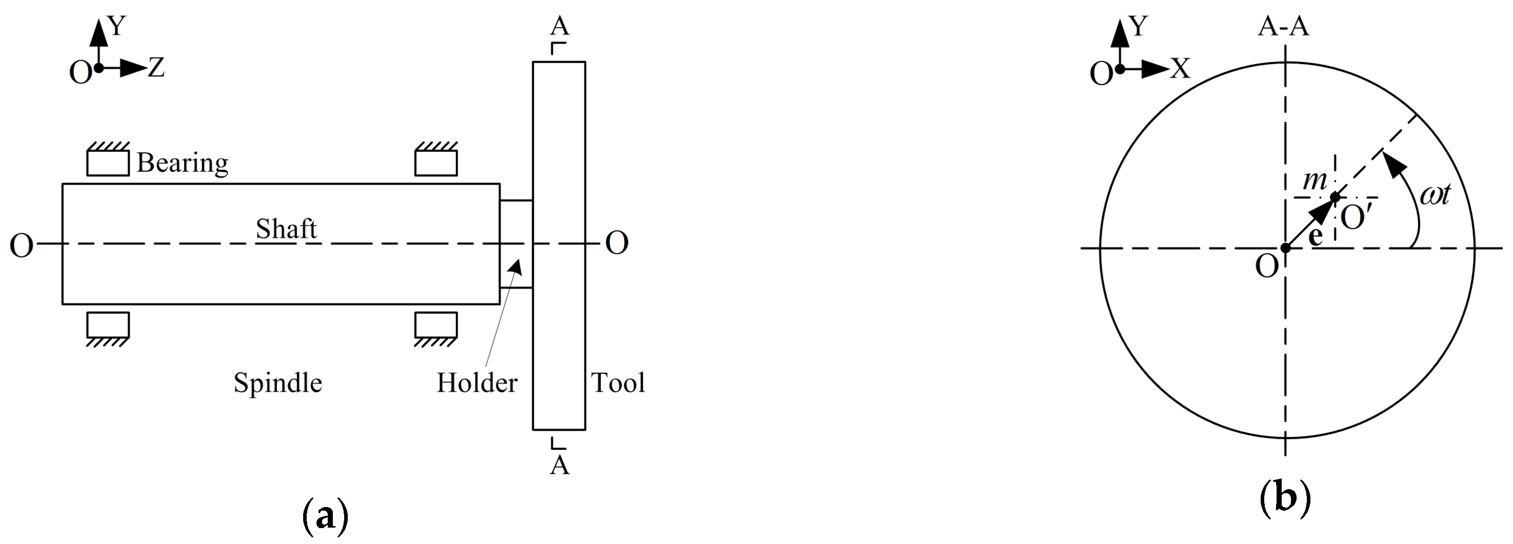
2.1. Mechanical Unbalance and Force
2.2. Electromagnetic Unbalance and Force
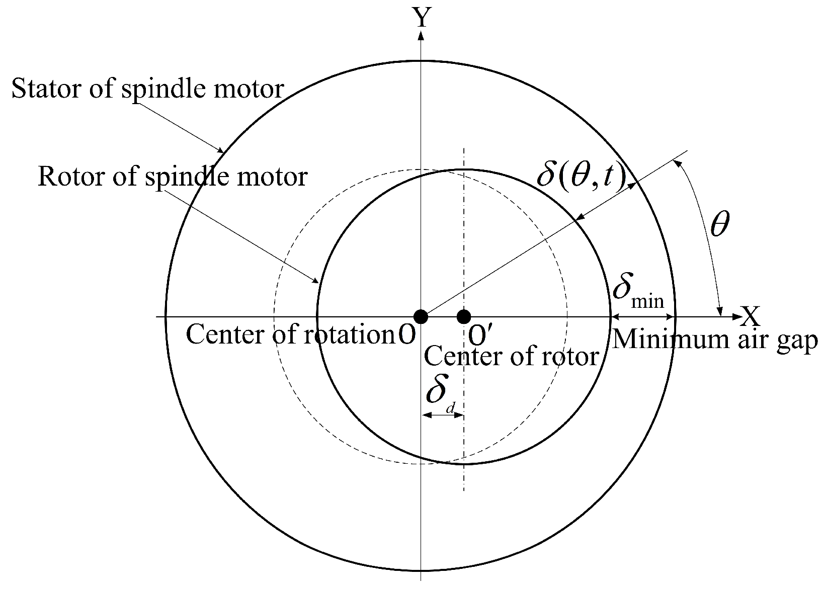
2.2.1. Characteristic of Spindle Motor with Dynamic Air Gap Eccentricity
2.2.2. Calculation Scheme of Electromagnetic Force of Spindle Motor
2.2.3. Electromagnetic Force of Spindle Motor without Eccentricity
2.2.4. UMP of Spindle Motor with Dynamic Air Gap Eccentricity
2.2.5. Main Component of UMP Affecting the Balancing Capacity
2.2.6. Quantitative Relationship between Unbalanced Mechanical and Electromagnetic Forces
3. Adaptive Balancing Approach of Motorized Spindle
3.1. Conventional Adaptive Balancing Method
3.2. Corrected Adaptive Balancing Method
4. Experiments
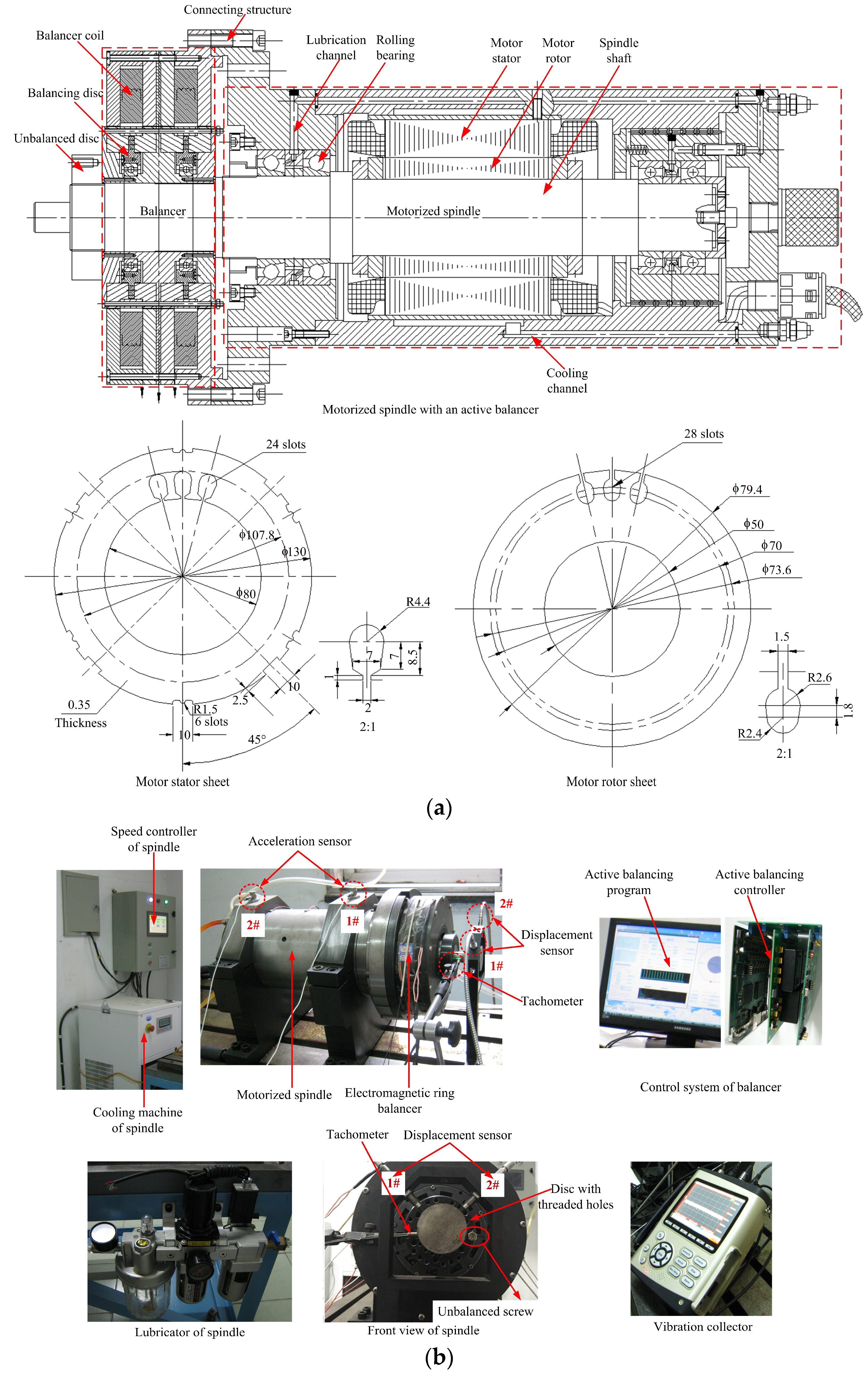
4.1. Motorized Spindle and Its Test Bed
4.2. Calculation of Balancing Correction Coefficient
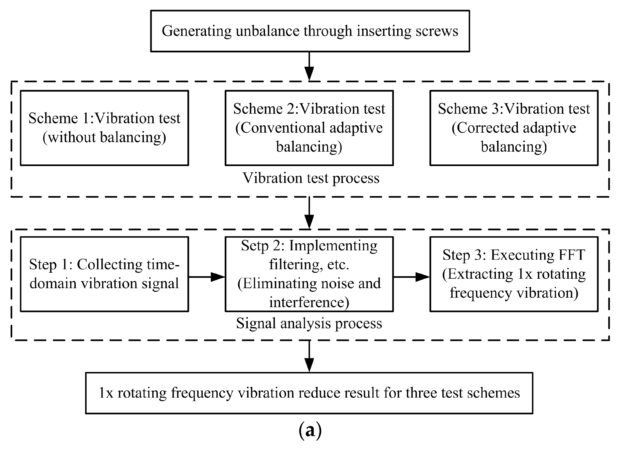
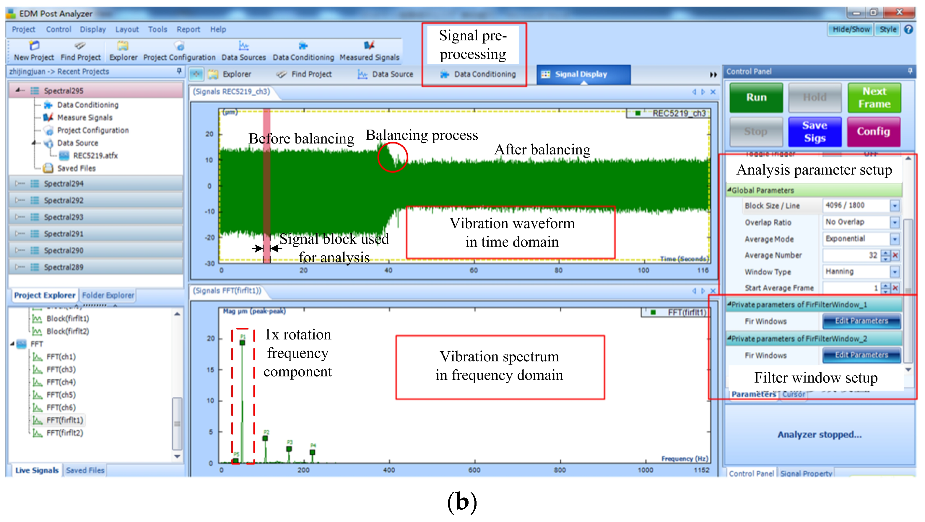
4.3. Experiment Design and Signal Analysis Scheme
4.4. Results and Discussion
5. Conclusions
6. Patents
Author Contributions
Funding
Acknowledgments
Conflicts of Interest
References
- López de Lacalle, L.N.; Lamikiz, A. Machine Tools for High Performance Machining; Springer: London, UK, 2009; pp. 75–128. [Google Scholar]
- Cao, H.R.; Zhang, X.W.; Chen, X.F. The concept and progress of intelligent spindles: A review. Int. J. Mach. Tools Manuf. 2017, 112, 21–52. [Google Scholar] [CrossRef]
- Urbikain, G.; Olvera, D.; López de Lacalle, L.N.; Elías-Zúñiga, A. Stability and vibrational behaviour in turning processes with low rotational speeds. Int. J. Adv. Manuf. Technol. 2015, 80, 871–885. [Google Scholar] [CrossRef]
- Urbikain, G.; Campa, F.J.; Zulaika, J.J.; López de Lacalle, L.N.; Alonso, M.A.; Collado, V. Preventing chatter vibrations in heavy-duty turning operations in large horizontal lathes. J. Sound Vib. 2015, 340, 317–330. [Google Scholar] [CrossRef]
- Urbikain, G.; Olvera, D.; López de Lacalle, L.N.; Elías-Zúñiga, A. Spindle speed variation technique in turning operations: Modeling and real implementation. J. Sound Vib. 2016, 383, 384–396. [Google Scholar] [CrossRef]
- Oleaga, I.; Pardo, C.; Zulaika, J.J.; Bustillo, A. A machine-learning based solution for chatter prediction in heavy-duty milling machines. Measurement 2018, 128, 34–44. [Google Scholar] [CrossRef]
- Liu, S.; Qu, L.S. A new field balancing method of rotor systems based on holospectrum and genetic algorithm. Appl. Soft Comput. 2008, 8, 446–455. [Google Scholar] [CrossRef]
- Xiang, S.T.; Yao, X.D.; Du, Z.C.; Yang, J.G. Dynamic linearization modeling approach for spindle thermal errors of machine tools. Mechatronics 2018, 53, 215–228. [Google Scholar] [CrossRef]
- Yang, A.S.; Yu, X.H.; Zhuang, J.R.; Lee, C.Y.; Hsieh, W.H. DOE-FEM based design improvement to minimize thermal errors of a high speed spindle system. Therm. Sci. Eng. Prog. 2018, 8, 525–536. [Google Scholar] [CrossRef]
- Abele, E.; Altintas, Y.; Brecher, C. Machine tool spindle units. Cirp Ann. Manuf. Technol. 2010, 59, 781–802. [Google Scholar] [CrossRef]
- Mikołajczyk, T.; Nowicki, K.; Bustillo, A.; Yu Pimenov, D. Predicting tool life in turning operations using neural networks and image processing. Mech. Syst. Signal Process. 2018, 104, 503–513. [Google Scholar] [CrossRef]
- Xul, J.; Zheng, X.H.; Zhang, J.J.; Liu, X. Vibration characteristics of unbalance response for motorized spindle system. Procedia Eng. 2017, 174, 331–340. [Google Scholar] [CrossRef]
- Deepthikumar, M.B.; Sekhar, A.S.; Srikanthan, M.R. Modal balancing of flexible rotors with bow and distributed unbalance. J. Sound Vib. 2013, 332, 6216–6233. [Google Scholar] [CrossRef]
- Bin, G.F.; Zhao, Q.L.; Jiang, Z.N.; Gao, J.J. Analysis of phase measurement based on influence coefficient and lag angle. J. Vib. Meas. Diagn. 2012, 32, 380–383. (In Chinese) [Google Scholar]
- Chen, K.Y.; Tung, P.C.; Tsai, M.T.; Fan, Y.H. A self-tuning fuzzy PID-type controller design for unbalance compensation in an active magnetic bearing. Expert Syst. Appl. 2009, 36, 8560–8570. [Google Scholar] [CrossRef]
- Shchurova, A.V. Modeling of the turbine rotor journal restoration on horizontal balancing machines. Procedia Eng. 2016, 150, 854–859. [Google Scholar] [CrossRef][Green Version]
- Shi, B.J.; Jing, M.Q.; Fan, H.W.; Wang, J.; Liu, H. Field balancing of grinding wheel spindle by single plane influence coefficient method. Mach. Electron. 2015, 5, 59–62. (In Chinese) [Google Scholar]
- Rajalingham, C.; Bhat, R.B.; Rakheja, S. Automatic balancing of flexible vertical rotors using a guided ball. Int. J. Mech. Sci. 1998, 40, 825–834. [Google Scholar] [CrossRef]
- Vegte, J.V. Continuous automatic balancing of rotating systems. J. Mech. Eng. Sci. 1964, 6, 264–269. [Google Scholar] [CrossRef]
- Hredzak, B.; Guo, G. New electromechanical balancing device for active imbalance compensation. J. Sound Vib. 2006, 294, 737–751. [Google Scholar] [CrossRef]
- Fan, H.W.; Jing, M.Q.; Wang, R.C.; Liu, H.; Zhi, J.J. New electromagnetic ring balancer for active imbalance compensation of rotating machinery. J. Sound Vib. 2014, 333, 3837–3858. [Google Scholar] [CrossRef]
- Yun, X.L.; Mei, X.S.; Jiang, G.D.; Hu, Z.B.; Zhang, Z.H. Design and experimental research of a spray-type integrated online dynamic balance terminal. J. Vib. Shock 2019, 38, 79–84. (In Chinese) [Google Scholar]
- Gosiewski, Z. Automatic balancing of flexible rotors, Part I: Theoretical background. J. Sound Vib. 1985, 100, 551–567. [Google Scholar] [CrossRef]
- Gosiewski, Z. Automatic balancing of flexible rotors, Part II: Synthesis of system. J. Sound Vib. 1987, 114, 103–119. [Google Scholar] [CrossRef]
- Moon, J.D.; Kim, B.S.; Lee, S.H. Development of the active balancing device for high-speed spindle system using influence coefficients. Int. J. Mach. Tools Manuf. 2006, 46, 978–987. [Google Scholar] [CrossRef]
- Dyer, S.W.; Ni, J. Adaptive influence coefficient control of single-plane active balancing systems for rotating machinery. J. Manuf. Sci. Eng. 2001, 123, 291–298. [Google Scholar] [CrossRef]
- Kim, J.S.; Lee, S.H. The stability of active balancing control using influence coefficients for a variable rotor system. Int. J. Adv. Manuf. Technol. 2003, 22, 562–567. [Google Scholar] [CrossRef]
- Dyer, S.W.; Ni, J.; Shi, J.J.; Shin, K.K. Robust optimal influence-coefficient control of multiple-plane active rotor balancing systems. J. Dyn. Syst. Meas. Control 2002, 124, 41–46. [Google Scholar] [CrossRef]
- Fan, H.W.; Jing, M.Q.; Liu, H.; Yang, T.T. New machine tool motorized spindle integrated with one electromagnetic ring balancer driven by optimal square wave. Proc. Inst. Mech. Eng. Part C J. Mech. Eng. Sci. 2015, 229, 1509–1522. [Google Scholar] [CrossRef]
- Fan, H.W.; Zhi, J.J.; Shi, B.J.; Jing, M.Q.; Liu, H. Adaptive rotor balancing algorithm and single-disk rotation test for electromagnetic balancer. J. Xi’an Jiaotong Univ. 2018, 52, 15–21, 29. (In Chinese) [Google Scholar]
- Fan, H.W.; Jing, M.Q.; Zhi, J.J.; Xin, W.H.; Li, M.; Liu, H. Development and validation of embedded control system for rotor online automatic balance. J. Vib. Meas. Diagn. 2015, 35, 746–751, 802. (In Chinese) [Google Scholar]
- Fan, H.W.; Jing, M.Q.; Wu, T.Q.; Zhang, C.; Liu, H. Experimental study on influence of automatic balancer on dynamic performance of motorized spindle. J. Test Meas. Technol. 2013, 27, 369–376. (In Chinese) [Google Scholar]
- Guo, D.; Chu, F.; Chen, D. The unbalanced magnetic pull and its effects on vibration in a three-phase generator with eccentric rotor. J. Sound Vib. 2002, 254, 297–312. [Google Scholar] [CrossRef]
- Chen, Y.X.; Zhu, Z.Q.; Ying, S.C. Analysis and Control of Motor Noise; Zhejiang University Press: Hangzhou, China, 1987; pp. 69–115. (In Chinese) [Google Scholar]
- Wang, J. Study on Online Active Balance of Motorized Spindle Considering the Influence of Air-Gap Eccentricity. Master’s Thesis, Xi’an Jiaotong University, Xi’an, China, 2016. (In Chinese). [Google Scholar]
- Liu, Z.Z.; Yang, Z.J.; Xiao, L.; Yu, L.C. To analyze and calculate unilateral magnetic force of an induction motor. J. Shandong Univ. 2004, 34, 59–62. (In Chinese) [Google Scholar]
- Zhang, C. Simulation Analysis and Experimental Study on Machine Tool Spindle. Master’s Thesis, Xi’an Jiaotong University, Xi’an, China, 2013. (In Chinese). [Google Scholar]
- Li, H.S.; Wu, S.; Kratz, H. FFT and wavelet-based analysis of the influence of machine vibrations on hard turned surface topographies. Tsinghua Sci. Technol. 2007, 12, 441–446. [Google Scholar] [CrossRef]


| Electromagnetic Force (EF) | No Eccentricity | Dynamic Eccentricity | ||
|---|---|---|---|---|
| Order | Frequency | Order | Frequency | |
| EF caused by main magnetic field | 4 | 4 | ||
| EF caused by interaction of the tooth harmonic magnetic fields of the stator and rotor | 0 | 0 | ||
| 4 | 4 | |||
| EF caused by interaction of the main and -order harmonic magnetic field | None | 1 | ||
| 3 | ||||
| EF caused by interaction of the stator tooth harmonic and -order harmonic magnetic field | None | 1 | ||
| 3 | ||||
| EF caused by interaction of the rotor tooth harmonic and -order harmonic magnetic field | None | 1 | ||
| EF caused by interaction of the rotor tooth harmonic and -order harmonic magnetic field | None | 1 | ||
| 3 | ||||
| EF caused by interaction of the stator tooth harmonic and -order harmonic magnetic field | None | 1 | ||
| Order of EF | First Order of MFD | Second Order of MFD | Order Number of EF | Frequency |
|---|---|---|---|---|
| 2 | 1 | 1 | ||
| 3 | 1 | |||
| 1 | ||||
| 1 | ||||
| 1 | ||||
| 1 |
| Parameter | Value | Parameter | Value |
|---|---|---|---|
| Outer diameter of stator (mm) | 130 | Outer diameter of rotor (mm) | 79.4 |
| Inner diameter of stator (mm) | 80 | Inner diameter of rotor (mm) | 50 |
| Length of stator core (mm) | 110 | Length of rotor core (mm) | 112 |
| Number of stator slots | 24 | Number of rotor slots | 28 |
| Pair number of magnetic poles | 2 | Length of air gap (mm) | 0.3 |
| Phase number of motor | 3 | Natural frequency of spindle rotor (Hz) | 586.7 [37] |
| Total mass of balancer–spindle rotor (kg) | 12.649 | Maximum balancing capacity of balancer (g·cm) | 38.55 |
| Kind | Type | Linear Range | Sensitivity |
|---|---|---|---|
| Acceleration sensor | Dytran3255A6 | ±25 g | 200 mV/g |
| Displacement sensor | JX20 | 0.5–1.5 mm | 4 V/mm |
| Case | Unbalanced Mass m (g) | Phase (°) | Vector Radius e (mm) |
|---|---|---|---|
| Case 1 | 4.5 | 0 | 36 |
| Case 2 | 9.0 | 180 |
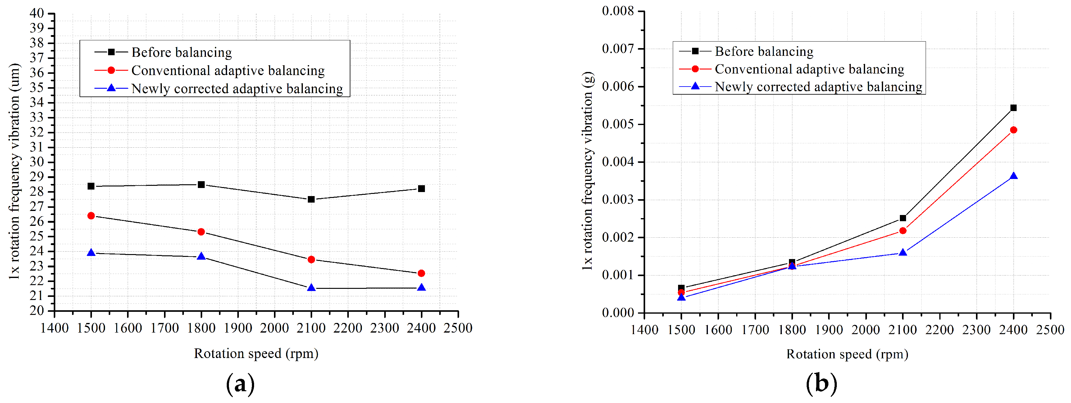
| Case 1 | ||||||||
| Displacement (um) | Acceleration (g) | |||||||
| Speed (rpm) | 1500 | 1800 | 2100 | 2400 | 1500 | 1800 | 2100 | 2400 |
| Before balancing | 28.39 | 28.50 | 27.50 | 28.23 | 0.00066 | 0.00134 | 0.00251 | 0.00544 |
| Conventional method | 26.40 | 25.32 | 23.46 | 22.53 | 0.00054 | 0.00124 | 0.00218 | 0.00485 |
| Reduction rate I (%) | 7.00 | 11.16 | 14.69 | 20.19 | 18.18 | 7.46 | 13.15 | 10.85 |
| Proposed method | 23.89 | 23.64 | 21.53 | 21.54 | 0.00040 | 0.00123 | 0.00159 | 0.00362 |
| Reduction rate II (%) | 15.85 | 17.05 | 21.71 | 23.70 | 39.39 | 8.21 | 36.65 | 33.46 |
| Rate difference (%) | 8.85 | 5.89 | 7.02 | 3.51 | 21.21 | 0.75 | 23.50 | 22.61 |
| Average (%) | 6.32 | 17.02 | ||||||
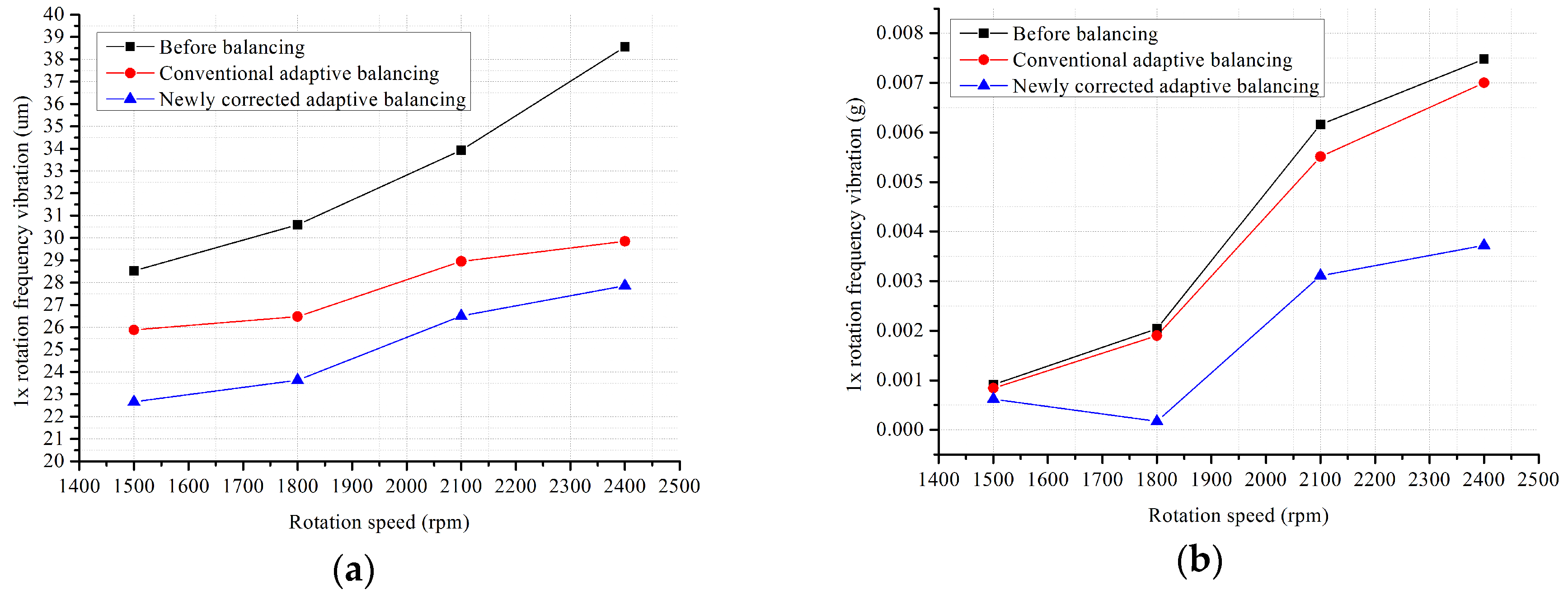
| Case 2 | ||||||||
| Displacement (um) | Acceleration (g) | |||||||
| Speed (rpm) | 1500 | 1800 | 2100 | 2400 | 1500 | 1800 | 2100 | 2400 |
| Before balancing | 28.53 | 30.59 | 33.93 | 38.56 | 0.00091 | 0.00204 | 0.00616 | 0.00748 |
| Conventional method | 25.88 | 26.48 | 28.95 | 29.85 | 0.00084 | 0.00190 | 0.00551 | 0.00700 |
| Reduction rate I (%) | 9.29 | 13.44 | 14.68 | 22.59 | 7.69 | 6.86 | 10.55 | 6.42 |
| Proposed method | 22.66 | 23.63 | 26.51 | 27.86 | 0.00062 | 0.00017 | 0.00311 | 0.00372 |
| Reduction rate II (%) | 20.57 | 22.75 | 21.87 | 27.75 | 31.87 | 91.67 | 49.51 | 50.27 |
| Rate difference (%) | 11.28 | 9.31 | 7.19 | 5.16 | 24.18 | 84.81 | 38.96 | 43.85 |
| Average (%) | 8.24 | 47.95 | ||||||
© 2020 by the authors. Licensee MDPI, Basel, Switzerland. This article is an open access article distributed under the terms and conditions of the Creative Commons Attribution (CC BY) license (http://creativecommons.org/licenses/by/4.0/).
Share and Cite
Fan, H.; Wang, J.; Shao, S.; Jing, M.; Liu, H.; Zhang, X. A Corrected Adaptive Balancing Approach of Motorized Spindle Considering Air Gap Unbalance. Appl. Sci. 2020, 10, 2197. https://doi.org/10.3390/app10062197
Fan H, Wang J, Shao S, Jing M, Liu H, Zhang X. A Corrected Adaptive Balancing Approach of Motorized Spindle Considering Air Gap Unbalance. Applied Sciences. 2020; 10(6):2197. https://doi.org/10.3390/app10062197
Chicago/Turabian StyleFan, Hongwei, Jin Wang, Sijie Shao, Minqing Jing, Heng Liu, and Xuhui Zhang. 2020. "A Corrected Adaptive Balancing Approach of Motorized Spindle Considering Air Gap Unbalance" Applied Sciences 10, no. 6: 2197. https://doi.org/10.3390/app10062197
APA StyleFan, H., Wang, J., Shao, S., Jing, M., Liu, H., & Zhang, X. (2020). A Corrected Adaptive Balancing Approach of Motorized Spindle Considering Air Gap Unbalance. Applied Sciences, 10(6), 2197. https://doi.org/10.3390/app10062197