Article

Coupling and Decoupling Measurement Method of Complete Geometric Errors for Multi-Axis Machine Tools

1
State Key Laboratory of Mechanical Transmission, Chongqing University, Chongqing 400044, China
2
College of Mechanical Engineering, Chongqing University, Chongqing 400044, China
*
Author to whom correspondence should be addressed.
Appl. Sci. 2020, 10(6), 2164; https://doi.org/10.3390/app10062164
Submission received: 11 February 2020 / Revised: 10 March 2020 / Accepted: 16 March 2020 / Published: 22 March 2020

Abstract

:

Featured Application

A new method of coupling and decoupling measurement is proposed to obtain complete geometric errors of multi-axis machine tools. It solves the problem of ignoring items of small angle errors in the traditional measurement method.

Abstract

Precision and ultra-precision machining technology rely mainly on the machine tools’ accuracy. To improve it, the measurement, calculation, prediction and control of geometric errors are critical. The traditional measurement methods have lower precision because of ignoring small angle errors. To obtain complete geometric errors of multi-axis machine tools, this paper proposes a new method of coupling and decoupling measurement. Specifically, we used a laser interferometer and dial indicators to measure 36 items of complete geometric errors of multi-axis machine tools. A homogeneous transformation matrix (HTM) was applied to model the error transfer route. The transfer law of complete errors for each machining point was explored and derived. Furthermore, we selected and calculated integrated errors of 36 machining points. Finally, we proved the correctness of the method by comparing the measurement result of a ball bar test and coupling and decoupling measurement of geometric errors. We found that items of small geometric angle errors have a greater impact on machining accuracy than those of geometric displacement errors. Complete geometric errors measured via the coupling and decoupling measurement method can evaluate integrated errors more precisely and comprehensively.

1. Introduction

In the past 10 years, the increasing interest in precision manufacturing engineering has heightened the need of advanced manufacturing technology. Precision manufacturing mainly includes precision and ultra-precision machining technology and manufacturing automation. The former pursues the precision of machining and the limit of surface quality, while the latter includes the automation of product design, manufacturing and management. Many parts and components used in aviation, aerospace, ships and cars are machined thorough precision and ultra-precision machining technology. As the hardware foundation of modern advanced manufacturing industry, the machining accuracy of multi-axis machine tools plays a critical role in developing and improving advanced manufacturing technology.
The errors discussed in this paper are the difference between the expected values of geometric dimension and the obtained measurement results. The geometrical deviations of a part resulting from successive machining set-ups originate from multiple error sources [1,2], such as positioning deviation [3], fixture errors, datum errors and machine tool errors [4]. Therefore, geometric errors of the machine tools constitute a large portion of the total machining error [5]. In terms of the geometric error analysis, Samper and Giordano proposed several error analysis models, such as 3D tolerancing models [6,7], a form defects expression method based on natural mode shapes of a discretized feature [8], and 2D and 3D assemblies modeling considering form errors of plane surfaces [9]. Grandjean described the form errors modeling in the assembly process [10]. Considering the variations and uncertainties of geometrical variations, Desrochers and Clément built a novel tolerance analysis representation model [11,12] and broadened the scope of the Jacobian-Torsor model [13]. In addition, Abenhaim and Desrochers investigated the profile measurements repeatability [14]. Ameta compared several tolerance analysis methods in common use [15,16] and constructed Tolerance-Maps to model the composite positional tolerancing [17]. In terms of the measurement instrument of geometric error, Chen used an auto-tracking laser interferometer to measure the geometric error of machine tools [18]. Peng used a double ball bar to measure geometric errors of the rotary axis on a multi-axis machine tool based on kinematic analysis [19,20,21]. Ibaraki used a laser scanning device to analyze sensitivity of machine geometric errors measurement [22,23]. Precision optics devices are recently and gradually applied to measure geometric errors of machine tools [24,25]. In terms of the measurement method, Yang applied the radial basis function (RBF) neural network approach to measure and compensate for geometric displacement errors [26]. Min applied machine vision to measure screw thread geometric errors [27]. Yang applied differential motion matrices to identify position-independent geometric errors of five-axis serial machine tools [28]. Lee researched the optimal on-machine measurement of position-independent geometric errors for rotary axes in five-axis machines with a universal head [29]. Comparison results of direct and indirect methods for geometric error measurement [30,31] indicate that because of ignoring angle errors, researches above lack completeness of geometric errors [32]. For example, Chen designed a novel six-degree-of freedom geometric error measurement system for a linear stage [33]. Hsieh designed a geometric error measurement system for linear guideway assembly and calibration [34].
At present, the measurement precision of most geometric errors is lower because of ignoring the items of small angle errors. To form a better view of the formation, measurement, transfer and integration process of geometric errors, we proposed a new measurement method to measure complete geometric errors of multi-axis machine tools.
Applying the coupling and decoupling measurement method proposed in this paper, we used laser interferometer and dial indicators to measure 36 items of complete geometric errors of multi-axis machine tools in Section 2. We investigated the motion transfer route of a multi-axis machine tool and applied a homogeneous transformation matrix (HTM) to model it. The transfer law of complete errors for each machining point was explored and derived in Section 3. Furthermore, we selected and calculated integrated errors of 36 machining points. Finally, we proved the correctness of the method by comparing the measurement result of a ball bar test and the result of coupling and decoupling measurement of geometric errors. Based on that, we evaluated the influences of displacement and angle errors on machining errors of multi-axis machine tools in Section 4. This paper proposes a new measurement method of complete geometric errors of multi-axis machine tools. The specific content and steps are shown in Figure 1. The paper is summarized in Section 5. Measurement data is shown in the Appendix A.

2. Measurement of Complete Geometric Errors

Most geometric errors are generated from the manufacturing and assembly stages. As the basis and premise of precision production, the measurement and control of geometric errors are of important significance. The measurement of geometric errors for a multi-axis machine tool relies on a variety of measurement methods, techniques and tools. Its control process aims to establish a transfer and mapping model from geometric errors to machining errors, and to research its quantitative transfer process.
Traditional measurement methods generally ignore small geometric angle errors. The resultant geometric error items are thus incomplete. Furthermore, the calculation and compensation accuracy of machining errors is lower. Due to the coupling between geometric error items, the coupling and decoupling measuring method is proposed in this paper to obtain complete geometric error items.

2.1. Complete Geometric Errors of Multi-Axis Machine Tools

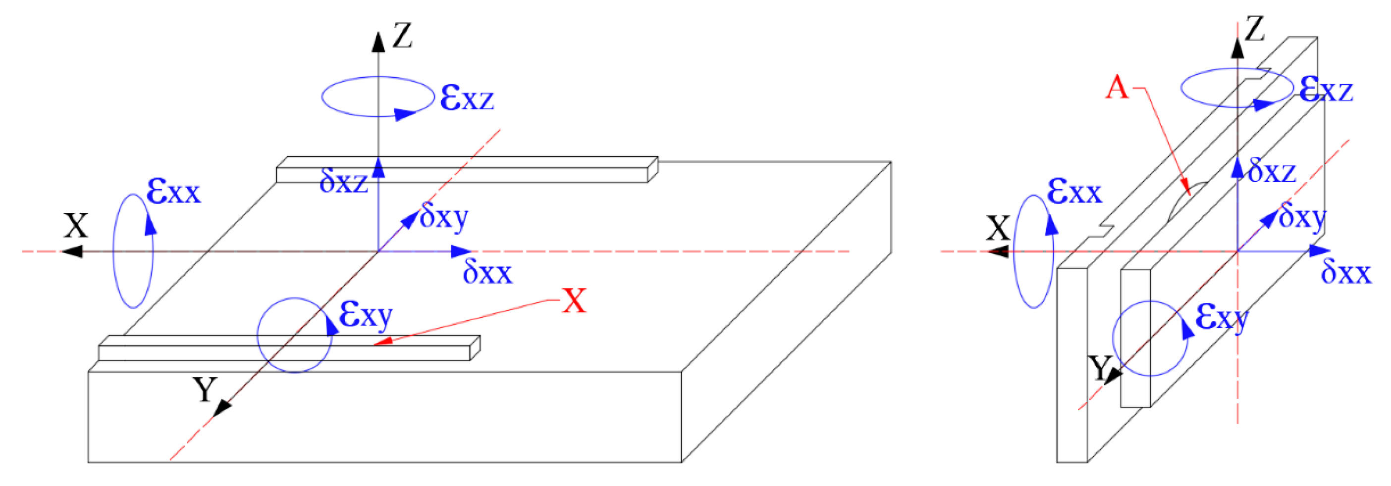
Complete geometric errors of multi-axis machine tools include geometric size, shape and position errors, which are displacement and angle errors or their coupling, in the final analysis. Although the orientation error caused by the inaccurate positioning of a workpiece and fixture is also one of the main errors in machined parts, it is mainly considered in the process of machining. Therefore, the orientation error is not taken into account in this paper. There are 6 items of geometric errors for each axis (translating or rotating axis): 3 items of geometric displacement errors and 3 items of geometric angle errors [35], as shown in Figure 2. Complete geometric errors of multi-axis machine tools include 36 items, as shown in Table 1. Among them, items of geometric errors are coupled with each other, except axial displacement errors.

2.2. Measurement of Axial Displacement Errors

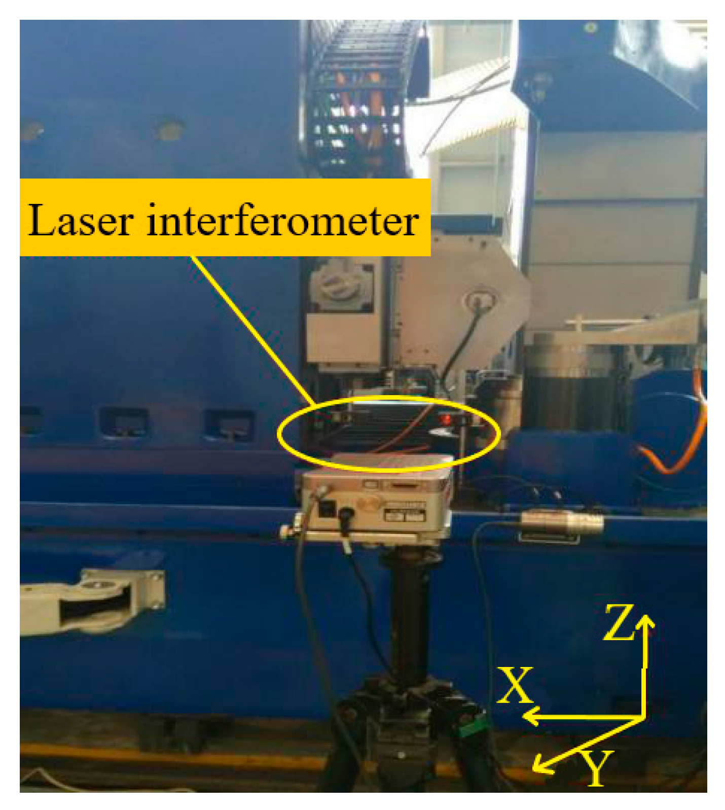
As Table 1 shows, δxx, δyy, δzz, δAx, δBy and δCz are the axial geometric errors of the X, Y, Z, A, B and C-axis, respectively. They are measured by a laser interferometer (Renishaw XL-80 laser system, resolution: 0.01 μm). The measurement of axial geometric displacement errors δxx is shown in Figure 3. The measurement points on the X-axis and A-axis are shown in Figure 4, where the points on the A-axis are at the end face.
As is shown in Figure 4, for the translation axes: X, Y and Z-axis, the axial geometric displacement errors of each point are obtained via recording the time difference between the laser interferometer transmitting and receiving infrared rays. The errors between the ideal position and the actual position of the points to be calculated, as in Equation (1):
δ x x i = p i ( i = 1 , 2 , , m ) .
Because there is no translation on the rotation axes: A, B, C-axis, their axial geometric errors are obtained as Equation (2):
δ A x = i = 1 n p i / n ( i = 1 , 2 , , n ) .

2.3. Measurement of Coupled Geometric Errors

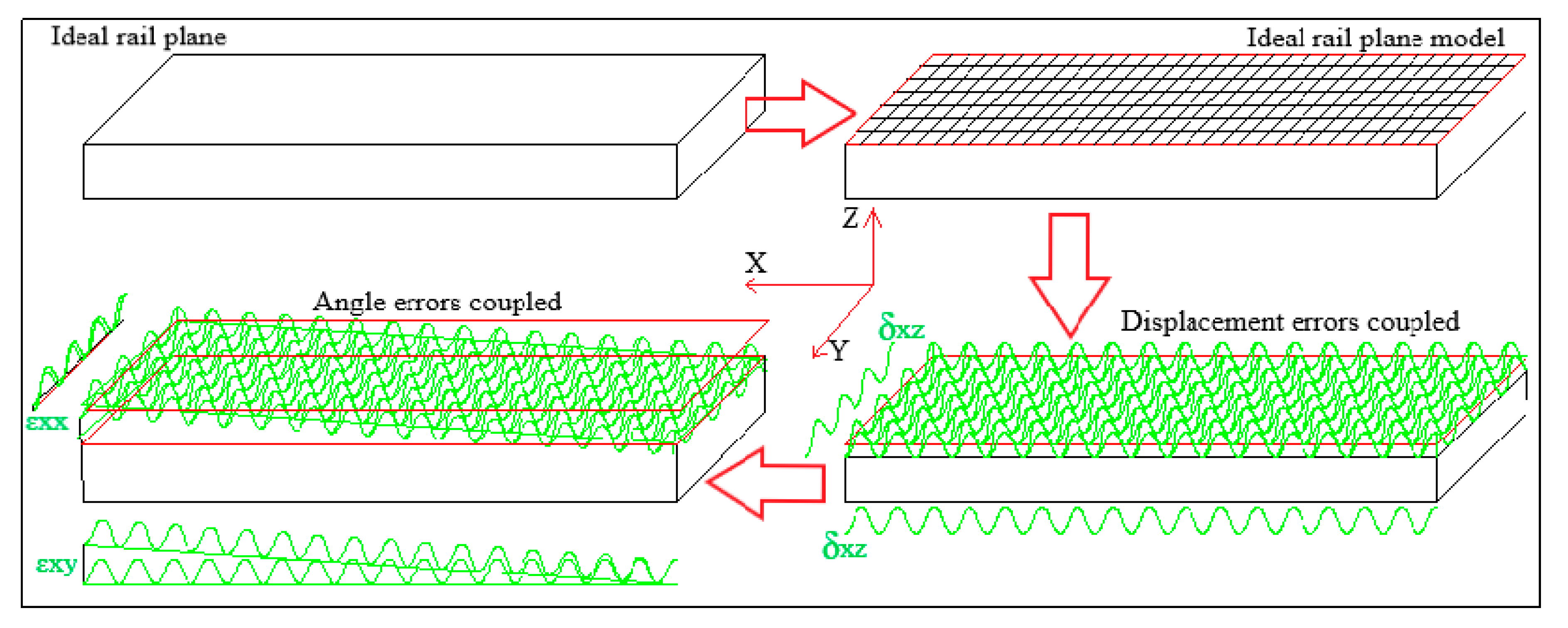
The translation rails of a multi-axis machine tool are generally planar, and their shape and position errors are coupled by transverse and longitudinal geometric displacement and angle errors, as shown in Figure 5.
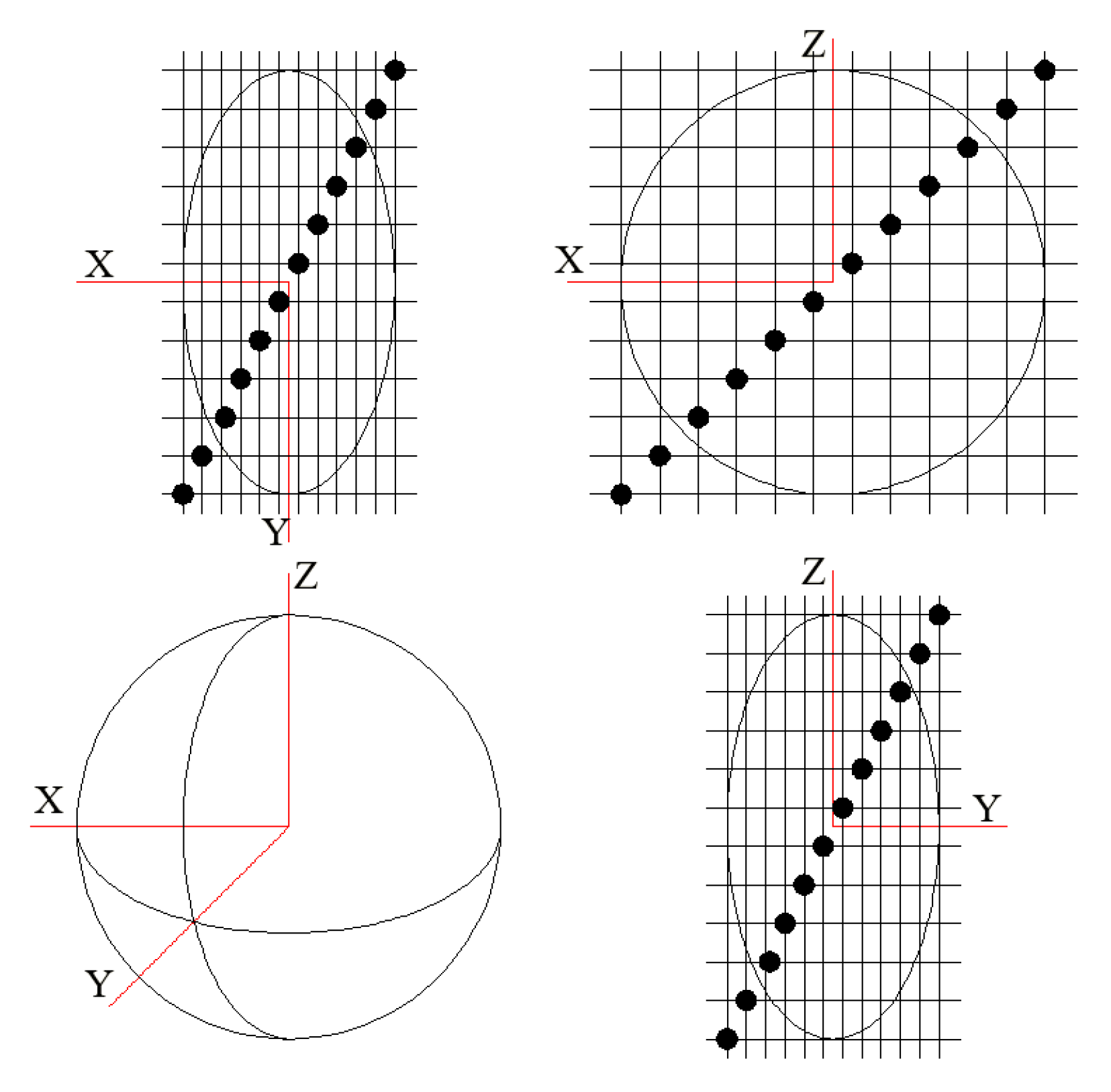
As is shown in Figure 5, in the XOY plane, coupling geometric error items of δxz along X and Y direction cause shape errors. Coupling geometric error items of εxx and εxy causes position errors; they can be decoupled in the XOZ and YOZ plane, as shown in Figure 6. The decoupling steps are as follows:
  • Set m and n points along the X and Y direction and measure shape errors of these m × n points.
  • Set the cross-sectional plane along each transverse and longitudinal line.
  • Fit shape errors along each transverse and longitudinal line.
  • Decouple error items of εxx and δxz in the YOZ cross-sectional plane, and εxy and δxz in the XOZ plane.
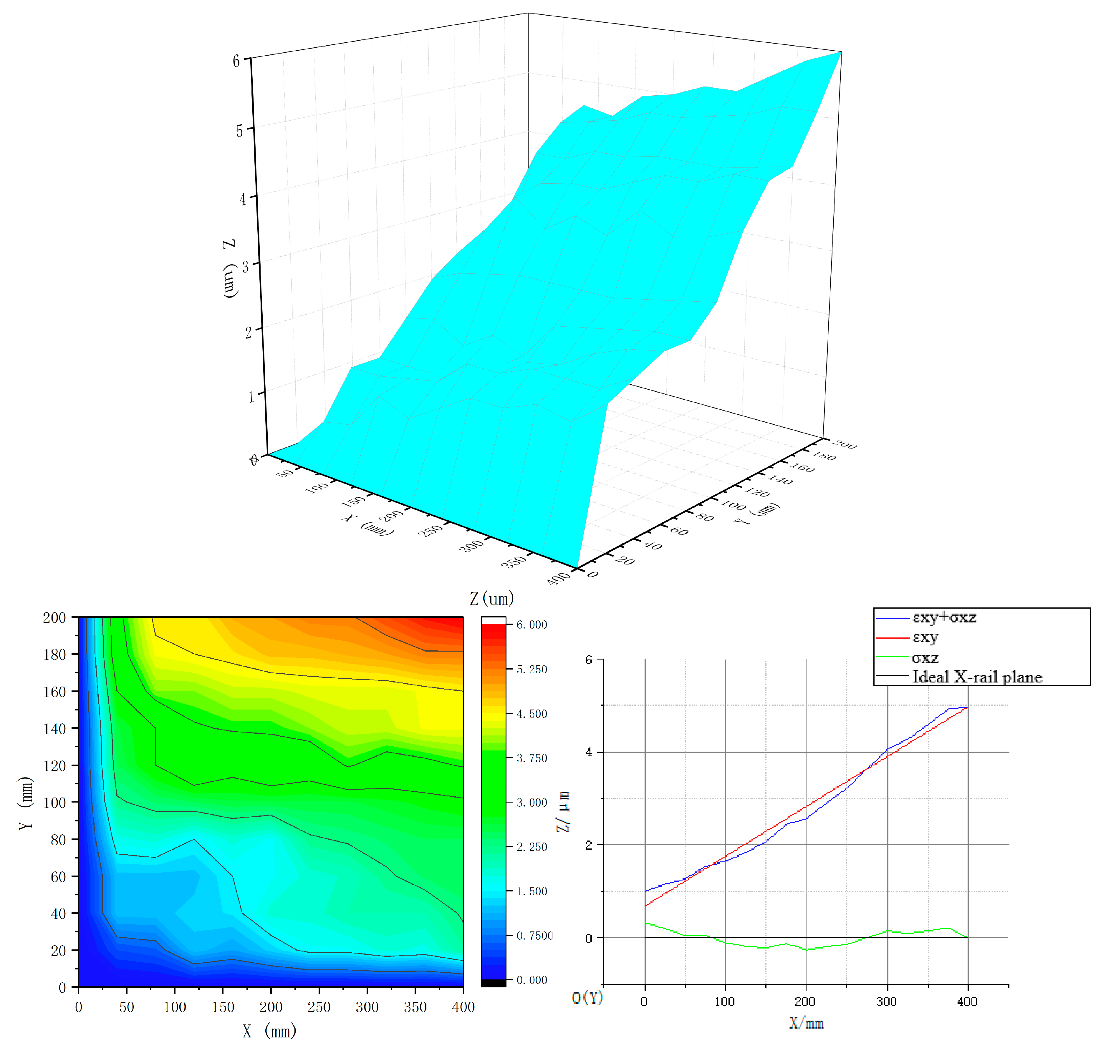
  • The tilt angles of the fitting line are angle error items of εxx and εxy. The difference between the shape errors and fitting values along each transverse and longitudinal line is the displacement errors item of εxx, as shown in Figure 7.
According to the figure above,
{ p i = j = 1 n p i j / n ( i = 1 , 2 , , m ) p j = i = 1 m p i j / n ( j = 1 , 2 , , n ) ,
{ k i · = tan ε x x i k · j = tan ε x y j ,
where k i · and k · j are the slopes of the fitting lines in the transverse and longitudinal cross-sectional planes, respectively.
In XOZ plane, the decoupling displacement and angle errors are obtained as Equations (5)–(7):
δ x z i = j = 1 n ( p i j k i · y j ) / n ( i = 1 , 2 , , m ) ,
ε x x i = arctan k i · ( i = 1 , 2 , , m ) ,
ε x y i = j = 1 n ( arctan k · j ) / n ( i = 1 , 2 , , m ) .
In YOZ plane, the decoupling displacement and angle errors are obtained as Equations (8)–(10):
δ x y i = j = 1 n ( p i j k · j x i ) / n ( i = 1 , 2 , , m ) ,
ε x x i = arctan k i · ( i = 1 , 2 , , m ) ,
ε x z i = j = 1 n ( arctan k · j ) / n ( i = 1 , 2 , , m ) .
Geometric error item of ε x x i (Equation (11)) is derived from Equation (6) and Equation (9):
ε x x i = ( ε x x ( X O Y ) i + ε x x ( X O Z ) i ) / 2 .
Finally, complete geometric errors of the X-axis are all obtained (Equations (1), (5), (7), (8), (10), and (11)). Similarly, complete geometric errors of the Y-axis and Z-axis can be measured by the same method and steps.
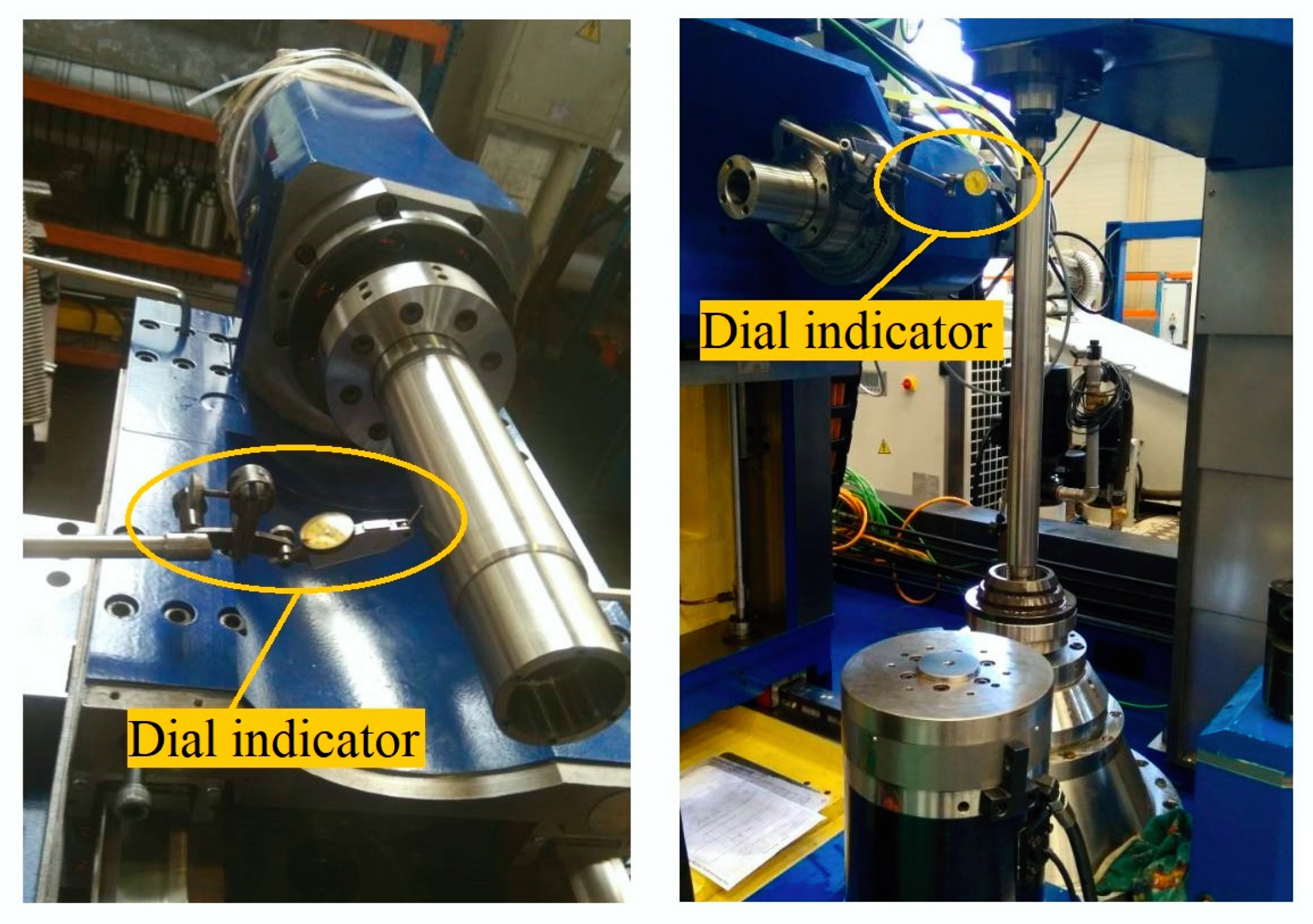
For the rotation axes: A, B and C-axis, considering that the final result is still expressed in the form of three-dimensional coordinates, we convert the cylindrical surfaces into partial planes to avoid the complex calculation process of transforming from 3D coordinates to cylindrical coordinates and then from cylindrical coordinates to 3D coordinates, as shown in Figure 8. By converting the cylindrical surfaces into partial planes, the geometrical shape defects of the surface will be transferred to the plane. Therefore, the transformed plane geometric defects described by measuring points are approximate to the geometrical shape defects of the surface. The coupled geometric errors of rotation axes can be measured by the coupling and decoupling method for planes ultimately, as shown in Figure 9. The measuring equipment is a dial indicator (TESA lever-type dial indicator S1, value of a scale division: 0.001 mm). The measurement data is shown in the Appendix A.

3. Geometric Error Transfer Modeling

Machining errors of the manufacturing process are the result of geometric error coupling, transferring and integrating. In addition to the measurement of geometric errors, the modeling of the transfer process is also particularly important. Homogeneous coordinate transformation theory can mathematically represent the rigid spatial motion without singularity. Based on the HTM, the transfer model is established in this paper.
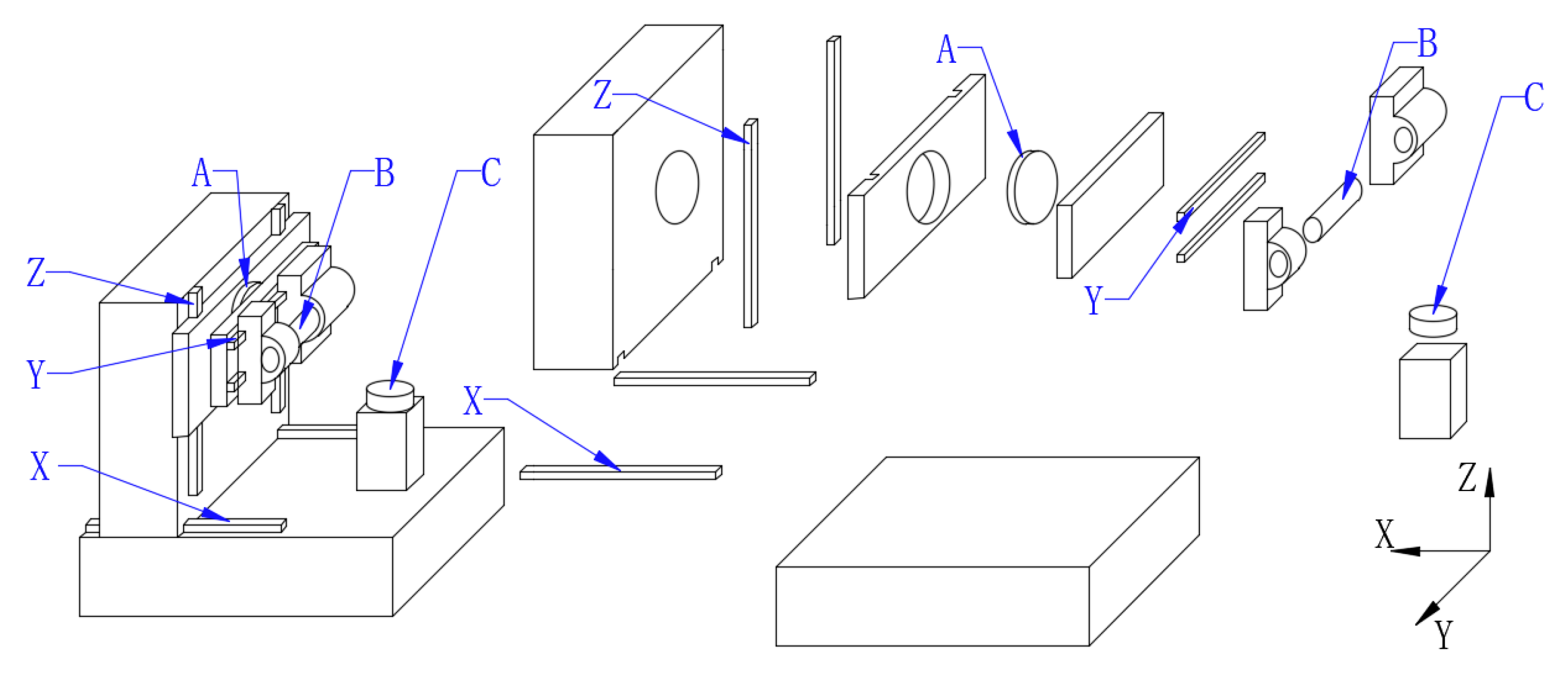
The multi-axis machine tool that was investigated is a high-efficiency grinding machine, as shown in Figure 10. Its physical and structure diagram is shown in Figure 11. The displacement and angle stroke parameters of each axis are as follows:
X (0–440) (mm)Y (0–220) (mm)Z (0–440) (mm)
A (−45–45) (Degree/°)B (0–360) (Degree/°)C (0–360) (Degree/°)
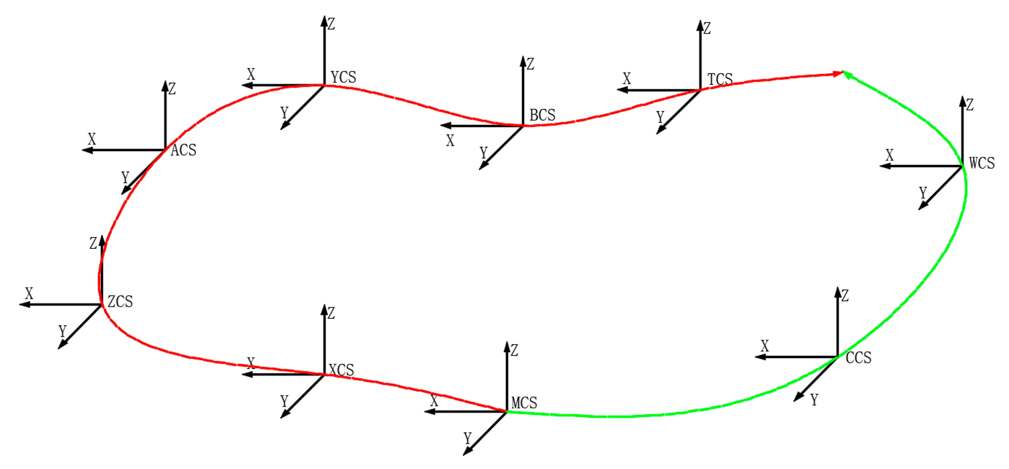
The geometric error transfer route is shown in Figure 12. MCS, XCS, YCS, ZCS, ACS, BCS, CCS, WCS, and TCS represent the reference coordinate system of the machine tool, X-axis, Y-axis, Z-axis, A-axis, B-axis, C-axis, the workpiece and the tool, respectively.

3.1. Geometric Error Transfer Modeling based on HTM

According to the Figure 12, the homogeneous coordinates of the workpiece and the tool are obtained as Equations (12) and (13):
T W i d e a l = T C i d e a l [ x w y w z w ] T ,   and
T T i d e a l = T X i d e a l T Z i d e a l T A i d e a l T Y i d e a l T B i d e a l [ x t y t z t ] ,
where T X i d e a l , T Y i d e a l , T Z i d e a l , T A i d e a l , T B i d e a l , T C i d e a l , T W i d e a l and T T i d e a l respectively represent the ideal homogeneous coordinates of X-axis, Y-axis, Z-axis, A-axis, B-axis, C-axis, the workpiece and tool. [ x w y w z w ] T and [ x t y t z t ] T represent the relative coordinates of the tool in the B-axis and the workpiece in the C-axis respectively.
Especially, when the relative motion of the tool and workpiece is in the ideal path, their homogeneous coordinates are obtained as Equation (14):
T W i d e a l = T T i d e a l .
As is analyzed in Section 2, due to the geometric errors during the actual machining process, the points on each axis deviate from the ideal position. The resultant actual homogeneous coordinates of the workpiece and tool under actual conditions are obtained as Equations (15) and (16):
T W a c t u a l = T C a c t u a l [ x w y w z w ] T ,
T T a c t u a l = T X a c t u a l T Z a c t u a l T A a c t u a l T Y a c t u a l T B a c t u a l [ x t y t z t ] ,
where T X a c t u a l , T Y a c t u a l , T Z a c t u a l , T A a c t u a l , T B a c t u a l and T C a c t u a l represent the actual homogeneous coordinates of X-axis, Y-axis, Z-axis, A-axis, B-axis and C-axis, respectively.
The difference between the actual homogeneous coordinates of the workpiece and tool is the coordinates of the actual machining point pi (xi, yi, zi), which can be expressed as (Equation (17)):
C p i = T W a c t u a l T T a c t u a l
The machining error of the point p0 (x0, y0, z0) to be machined on the relative motion trajectory of the tool and workpiece is obtained as Equation (18):
E p 0 = C p i C p 0 ,
where C p 0 and C p i represent the coordinates of the ideal and actual machining point, respectively.
The initial homogeneous transformation matrices of each axis under ideal conditions and complete geometric errors are obtained as Equations (19)–(30):
T X i d e a l = [ 1 0 0 x i 0 1 0 0 0 0 1 0 0 0 0 1 ] ,
T Y i d e a l = [ 1 0 0 0 0 1 0 y i 0 0 1 0 0 0 0 1 ] ,
T Z i d e a l = [ 1 0 0 0 0 1 0 0 0 0 1 z i 0 0 0 1 ] ,
T A i e d a l = [ 1 0 0 0 0 cos α i sin α i 0 0 sin α i cos α i 0 0 0 0 1 ] ,
T B i d e a l = [ cos β i 0 sin β i 0 0 1 0 0 sin β i 0 cos β i 0 0 0 0 1 ] ,
T C i d e a l = [ cos γ i sin γ i 0 0 sin γ i cos γ i 0 0 0 0 1 0 0 0 0 1 ] ,
T X a c t u a l = [ cos ε x y cos ε x z sin ε x x sin ε x y cos ε x z cos ε x x sin ε x z sin ε x x sin ε x z + cos ε x x sin ε x y cos ε x z x i + δ x x cos ε x y sin ε x z cos ε x x cos ε x z + sin ε x x sin ε x y sin ε x z cos ε x x sin ε x y sin ε x z sin ε x x cos ε x z δ x y sin ε x y sin ε x x cos ε x y cos ε x x cos ε x y δ x z 0 0 0 1 ] ,
T Y a c t u a l = [ cos ε y y cos ε y z sin ε y x sin ε y y cos ε y z cos ε y x sin ε y z sin ε y x sin ε y z + cos ε y x sin ε y y cos ε y z δ y x cos ε y y sin ε y z cos ε y x cos ε y z + sin ε y x sin ε y y sin ε y z cos ε y x sin ε y y sin ε y z sin ε y x cos ε y z y i + δ y y sin ε y y sin ε y x cos ε y y cos ε y x cos ε y y δ y z 0 0 0 1 ] ,
T Z a c t u a l = [ cos ε z y cos ε z z sin ε z x sin ε z y cos ε z z cos ε z x sin ε z z sin ε z x sin ε z z + cos ε z x sin ε z y cos ε z z δ z x cos ε z y sin ε z z cos ε z x cos ε z z + sin ε z x sin ε z y sin ε z z cos ε z x sin ε z y sin ε z z sin ε z x cos ε z z δ z y sin ε z y sin ε z x cos ε z y cos ε z x cos ε z y z i + δ z z 0 0 0 1 ] ,
T A actual = [ cos ε A y cos ε A z sin ( α i + ε A x ) sin ε A y cos ε A z cos ( α i + ε A x ) sin ε A z sin ( α i + ε A x ) sin ε A z + cos ( α i + ε A x ) sin ε A y cos ε A z δ A x cos ε A y sin ε A z cos ( α i + ε A x ) cos ε A z + sin ( α i + ε A x ) sin ε A y sin ε A z cos ( α i + ε A x ) sin ε A y sin ε A z sin ( α i + ε A x ) cos ε A z δ A y sin ε A y sin ( α i + ε A x ) cos ε A y cos ( α i + ε A x ) cos ε A y δ A z 0 0 0 1 ] ,
T B actual = [ cos ( β + ε B y ) cos ε B z sin ε B x sin ( β + ε B y ) cos ε B z cos ε B x sin ε B z sin ε B x sin ε B z + cos ε B x sin ( β + ε B y ) cos ε B z δ B x cos ( β + ε B y ) sin ε B z cos ε B x cos ε B z + sin ε B x sin ( β + ε B y ) sin ε B z cos ε B x sin ( β + ε B y ) sin ε B z sin ε B x cos ε B z δ B y sin ( β + ε B y ) sin ε B x cos ( β + ε B y ) cos ε B x cos ( β + ε B y ) δ B z 0 0 0 1 ] ,
T C actual = [ cos ε C y cos ( γ + ε C z ) sin ε C x sin ε C y cos ( γ + ε C z ) cos ε C x sin ( γ + ε C z ) sin ε C x sin ( γ + ε C z ) + cos ε C x sin ε C y cos ( γ + ε C z ) δ C x cos ε C y sin ( γ + ε C z ) cos ε C x cos ( γ + ε C z ) + sin ε C x sin ε C y sin ( γ + ε C z ) cos ε C x sin ε C y sin ( γ + ε C z ) sin ε C x cos ( γ + ε C z ) δ C y sin ε C y sin ε C x cos ε C y cos ε C x cos ε C y δ C z 0 0 0 1 ] ,
where xi, yi and zi represent the displacement of the X-axis, Y-axis and Z-axis respectively. α, β and γ represent the rotation angle of the axes A-axis, B-axis and C-axis, respectively.

3.2. Forward and Inverse Kinematics Solutions

Forward and inverse kinematics aims to study the process of motion transfer, which is the significant basis of deriving the complete geometric errors law. Their solutions are essential for exploring the relationship between the machining posture of the tool and workpiece and the translation and rotation position of each axis.
(1) The forward kinematics solution
Forward kinematic solution aims to determine the machining point according to the motion of each axis. In this way, the complete geometric errors measured in Section 2 are integrated and converted into machining errors corresponding to the translation and rotation position of each axis.
According to Equations (12), (13), and (19)–(24), the position of the tool and workpiece are obtained by Equations (31) and (32):
T W i d e a l = [ x w cos γ i y w sin γ i x w sin γ i + y w cos γ i z w 1 ] ,
T T i d e a l = [ x t cos β i + y t sin α i sin β i + z t cos α i sin β i + x i y t cos α i z t sin α i + y i x t sin β i + y t sin α i cos β i + z t cos α i cos β i + z i 1 ] ,
where the coordinates of the workpiece (xw, yw, zw) relative to the C-axis and the tool (xt, yt, zt) relative to the B-axis are determined directly by the machine structure. Moreover, (xw, yw, zw) is (0, 0, 400) and (xt, yt, zt) is (200, 0, 0).
With respect to the translation and rotation motion of each axis, the coordinates of the machining point are derived as below (Equation (33)) from Equations (17), (31), and (32). Since (xw, yw, zw) and (xt, yt, zt) are known, the forward kinematics solution pm (xm, ym, zm) is obtained as Equation (33):
{ 200 cos β i + x i 200 cos γ i = x m y i = y m 200 sin β i + z i 400 = z m .
(2) The inverse kinematics solution [36]
The inverse kinematics solution aims to determine the translation and rotation motion of each axis according to the coordinates (x0, y0, z0) of the point p0 to be machined in the ideal relative motion trajectory of the tool and workpiece, which is more significant than the forward kinematics solution in the machine design stage. Similarly, its inverse kinematics equation is obtained as follows in Equation (34):
{ x t cos β i + y t sin α i sin β i + z t cos α i sin β i + x i x w cos γ i + y w sin γ i = x 0 y t cos α i z t sin α i + y i x w sin γ i y w cos γ i = y 0 x t sin β i + y t sin α i cos β i + z t cos α i cos β i + z i z w = z 0 .
Obviously, there are six unknown numbers: xi, yi, zi, αi, βi, γi, which cannot be solved from the 3 equations above. Actually, for the multi-axis grinding machine tool investigated in this paper, the A-axis only participates in the positioning process, not in the machining process. Thus αi is set as constant α according to the thickness d and helix angle β of the gear to be machined. Because the B-axis and the C-axis keep rotating in the whole machining process, their mean values are selected as the calculation factor. Finally, the inverse kinematics solution is solved as:
{ 200 cos β + x i 200 cos γ = x m y i = y m 200 sin β + z i 400 = z m .

4. Calculation of Integrated Geometric Errors

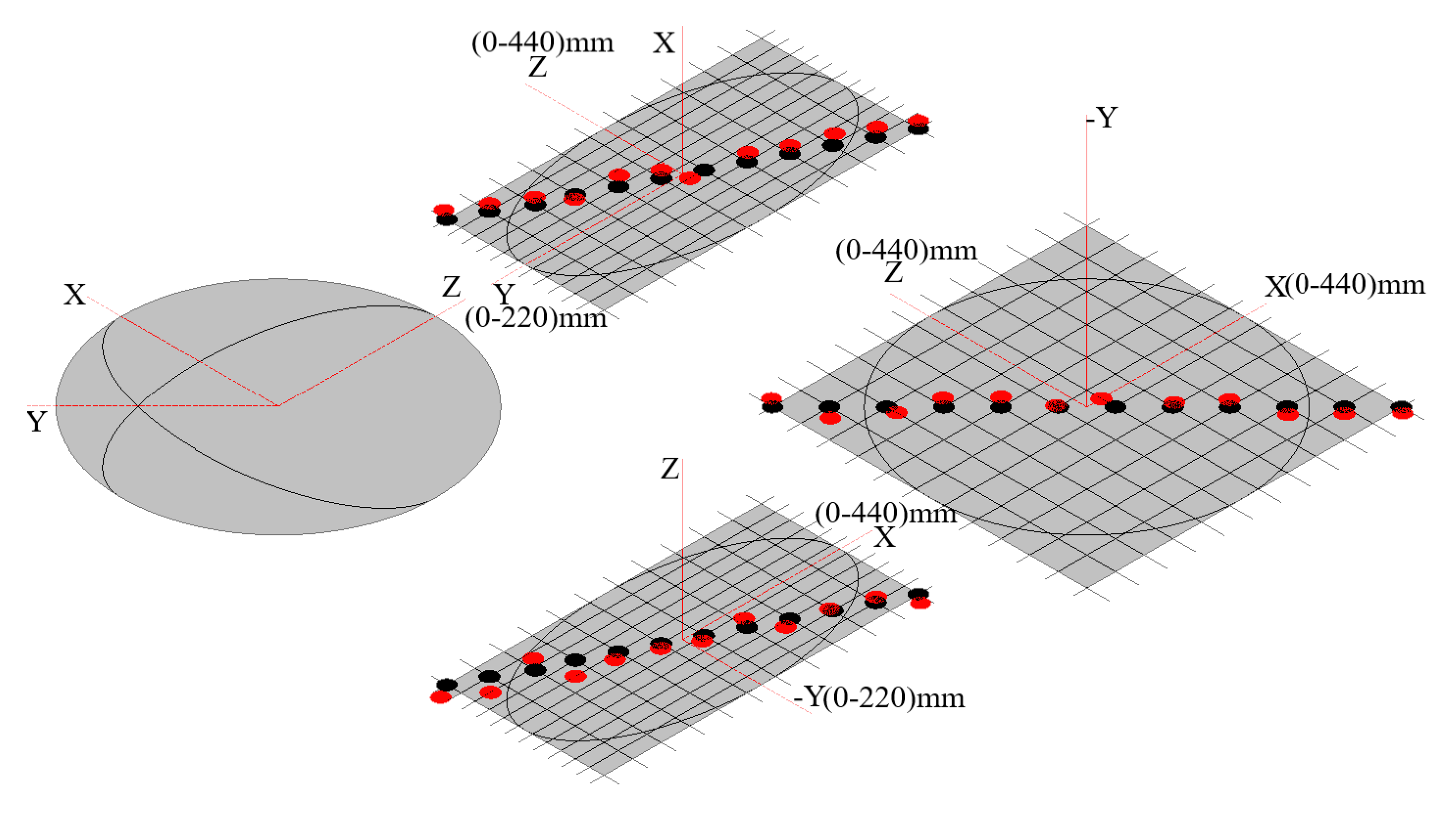
For each axis, 12 points are selected and their complete geometric errors are measured in this paper. In this way, the integrated geometric errors of near 3 million (126) machining points are obtained. Limited to the length of the paper, as an example, this paper only performs integrated error calculation for the 36 machining points as shown in Figure 13.
Take pi (xi, yi, zi, αi, βi, γi) = (0, 0, 0, 0, 0, 0) as an example; its complete geometric errors (δx, δy, δz, εx, εy, εz) are obtained as follows:
X:( −1.2, 3.0, 4.2, 1.25, 0.85943, 0.61593)A:( −2.4, −4.0, −6.2, 1.0, −0.862, 0.563)
Y:( −3.8, 1.0, 6.4, 0.63584, 0.56, 0.27658)B:(5.6, 0.5, ₋4.4, −0.267, 0.87, −0.581)
Z:( −3.4, −5.6, 0.2, 0.33456, 0.42638, 0.06)C:( −4.2, −2.4, 3.2, 0.264, −0.795, 0.4)
According to Equations (15)–(18), and (25)–(30), its actual HTMs and integrated error are obtained as follows in Equations (36)–(44):
T X a c t u a l = [ 0.99983 0.01064 0 . 01508 - 0 . 0012 0.01075 0.99992 0.00703 0 . 0030 0.01500 0.00724 0.99986 0 . 0042 0 0 0 1 ] ,
T Y a c t u a l = [ 0.99997 0.00475 0.00658 0.0038 0.00483 0.99993 0.01107 0.0010 0.00653 0.01110 0.99992 0.0064 0 0 0 1 ] ,
T Z a c t u a l = [ 0 . 99997 0 . 00219 0 . 00743 - 0 . 0034 0.00215 0 . 99998 - 0 . 00586 - 0 . 0056 0 . 00744 0 . 00584 0 . 99996 0 . 0002 0 0 0 1 ] ,
T A actual = [ 0.99984 0.00982 0.01505 0.0024 0.00982 0.99995 0.00043 0.0040 0.01504 0.00058 0.99989 0.0062 0 0 0 1 ] ,
T B actual = [ 0.99983 0.01007 0.01523 0.0056 0.01014 0.99994 0.00451 0.0005 0.01518 0.00466 0.99987 0.0044 0 0 0 1 ] ,
T C actual = [ 0.99988 0.00705 0.01384 0.0042 0.00698 0.99996 0.00470 0.0024 0.01387 0.00461 0.99989 0.0032 0 0 0 1 ] ,
T t a c t u a l = [ 0.99971 0.00836 0 . 02257 - 0 . 00454 0.00865 0.99988 0.01281 - 0 . 00264 0.02245 0.01305 0.99967 0 . 0044 0 0 0 1 ] [ 200 0 0 1 ] = [ 193.93746 1.72736 4.4856 1 ] ,
T w actual = [ 0.99988 0.00705 0.01384 0.0042 0.00698 0.99996 0.00470 0.0024 0.01387 0.00461 0.99989 0.0032 0 0 0 1 ] [ 0 0 400 1 ] = [ - 5 . 5402 - 1 . 8824 399 . 9592 1 ] ,   and
E = [ 200 0 400 0 ] [ 193.93746 1.72736 4.4856 1 ] + [ - 5 . 5402 - 1 . 8824 399 . 9592 1 ] = [ 0.52234 3.60976 4.5264 0 ] .
Similarly, geometric errors of all machining points selected are obtained as shown in Figure 14.
In the traditional measurement method, the small geometric angle errors are not taken into consideration; they are calculated as 0. The integrated geometric error is expressed as Equation (44). The first term in Equations (44) and (45) is the expected relative distance of the workpiece from the tool. The second item is the actual geometric position of the workpiece, and the third item is the actual geometric position of the tool.
E = [ 200 0 400 0 ] [ 199 . 9948 - 0 . 0051 0 . 0002 1 ] + [ - 0 . 0042 - 0 . 0024 400 . 0032 1 ] = [ 0 . 001 0 . 0027 0 . 0002 0 ]
Compared with the measurement method of the ball bar test, not taking the small geometric angle errors into consideration, as shown in Figure 15, the calculation result (Equation (44)) of integrated geometric errors by the coupling and decoupling measurement method shows the same result (0.1 mm). The correctness of the method proposed in this paper is proved.
As is shown in Equations (41) and (42), the positions of the tool relative to the B-axis and the workpiece relative to the C-axis, the relative coordinates of (xt, yt, zt) and (xw, yw, zw), are the cardinality of geometric error transfer, which indicates that the larger the sizes of the machine tool structures are, the larger the integrated geometric errors are.
However, as is shown in Equation (43) and Figure 14, once complete geometric errors including the small geometric angle errors are taken into consideration, the integrated geometric errors of machining points will reach a higher level (1 mm), which indicates that small geometric errors have an inevitable impact on the precision of the multi-axis machine tool. Thus, the measurement and consideration of complete geometric errors is significant and necessary.

5. Conclusions

Complete geometric errors of multi-axis machine tools are measured by the coupling and decoupling method proposed in this paper. Based on the HTM, the transfer law of geometric errors is researched. The correctness of the coupling and decoupling measurement method is proved via the comparison result with the traditional method. The geometrical error transfer modeling can be referred to other similar researches. The calculation result of integrated geometric errors considering the small angle errors shows that:
(1) Considering complete geometric errors, actual integrated geometric errors of multi-axis machine tools investigated have a higher level (1 mm), about 10 times, than the result of the traditional measurement method.
(2) The impact of items of small geometric angle errors is more significant than that of items of geometric displacement errors.
(3) The larger the sizes of the machine tool structures are, the larger the integrated geometric errors are.

Author Contributions

Conceptualization, H.W. and S.Z.; methodology, H.W.; validation, H.W., S.Z. and Y.L.; formal analysis, H.W.; investigation, S.Z.; resources, Y.R.; data curation, Y.L.; writing—original draft preparation, H.W.; writing—review and editing, Y.R., S.Z. and H.W.; project administration, Y.R.; funding acquisition, Y.R. All authors have read and agreed to the published version of the manuscript.

Funding

This research was funded by the National Natural Science Foundation, China, grant number 51835001; 51705048 and the National Major Scientific and Technological Special Project for “High-grade CNC and Basic Manufacturing Equipment”, China, grant number 2016ZX04004-005; 2018ZX04032-001; 2019ZX04005-001.

Acknowledgments

The authors gratefully acknowledge the valuable comments and suggestions given by the anonymous referees and editor.

Conflicts of Interest

The authors declare no conflict of interest.

Appendix A

The axial displacement errors δxx, δyy, δzz, δAx, δBy, δCz are measured by the laser interferometer. In accordance with the recommendation of GUM (Guide to the Expression of Uncertainty in Measurement), we used Type B evaluation method to calculate the expanded uncertainty U95 = 0.022 μm. The coupled geometric errors δxy, δxz, εxx, εxy, εxz, δyx, δyz, εyx, εyy, εyz, δzx, δzy, εzx, εzy, εzz, δAy, δAz, εAx, εAy, εAz, δBx, δBz, εBx, εBy, εBz, δCx, δCy, εCx, εCy, εCz are measured by the dial indicator. In accordance with the recommendation of GUM, we used the Type B evaluation method to calculate the expanded uncertainty U95 = 1.2 μm.
Table A1. Complete geometric errors of the X-axis.
i123456789101112
xi04080120160200240280320360400440
δxx(μm)−1.21.63.24.06.23.21.42.44.26.27.43.5
δxy(μm)3.01.40.6−2.2−2.8−3.2−1.41.61.82.60.40.1
δxz(μm)4.21.82.6−1.4−2.6−3.8−1.42.81.63.61.20.7
εxx(°)1.2511.250.750.63−0.25−0.5−0.250.130.50.60.4
εxy(°)0.85943
εxz(°)0.61593
Table A2. Complete geometric errors of the Y-axis.
i123456789101112
Yi(mm)020406080100120140160180200220
δyx(μm)−3.82.42.6−4.4−4.2−3.2−2.24.0−4.04.2−3.4−1.0
δyy(μm)1.001.44.26.62.20.83.45.45.83.03.0
δyz(μm)6.42.2−4.2−1.8−2.04.64.45.68.45.23.22.9
εyx(°)0.63584
εyy(°)0.560.070.350.270.850.48−0.220.110.8700.770.37
εyz(°)0.27658
Table A3. Complete geometric errors of the Z-axis.
i123456789101112
zi04080120160200240280320360400440
δzx(μm)−3.43.61.2−2.4−2.60.87.24.8−2.80.60.80.7
δzy(μm)−5.65.4−6.8−2.26.2−6.07.6−2.60.22.80.8−0.0
δzz(μm)0.2−2.2−3.8−3.4−2.4−2.6−3.40.60.8−3.40.6−1.7
εzx(°)0.33456
εzy(°)0.42638
εzz(°)0.06−0.45-0.89−0.26−0.05−0.190.590.35−0.42−0.860.77−0.12
Table A4. Complete geometric errors of the A-axis.
i123456789101112
αi (°)0306090120150180210240270300330
δAx(μm)−2.4
δAy(μm)−4.0−2.8−3.2−1.6−1.8−1.45.2-5.83.21.60.4−0.9
δAz(μm)−6.2−5.80.60.6−4.24.03.62.8−5.0−3.8−1.8−1.3
εAx(°)1−0.02−0.430.71−0.76−0.730.55−0.93−0.31−0.32−0.05−0.03
εAy(°)−0.862
εAz(°)0.563
Table A5. Complete geometric errors of the B-axis.
i123456789101112
βi(°)−45−37.5−30−22.5−15−7.507.51522.53037.5
δBx(μm)−4.2−1.6−2.2−2.44.8−3.65.61.60.62.20.80.1
δBy(μm)0.5
δBz(μm)2.6−0.40.22.2−3.2−2.8−4.4−3.6−3.4−1.84.0−0.9
εBx(°)−0.267
εBy(°)0.62−0.170.940.880.450.750.870.240.160.480.200.49
εBz(°)−0.581
Table A6. Complete geometric errors of the C-axis.
i123456789101112
γi(°)0306090120150180210240270300330
δCx(μm)−4.22.87.80.83.41.60.6−6.4−1.2−5.65.40.4
δCy(μm)−2.4−3.20.41.62.84.8−2.20.21.0−3.61.80.1
δCz(μm)3.2
εCx(°)0.264
εCy(°)−0.795
εCz(°)0.40.2−0.1−0.50.40.3−0.30.4−0.50.1−0.20.0

References

  1. Villeneuve, F.; Legoff, O.; Landon, Y. Tolerancing for manufacturing: A three-dimensional model. Int. J. Prod. Res. 2001, 39, 1625–1648. [Google Scholar] [CrossRef]
  2. Vignat, F.; Villeneuve, F. 3D transfer of tolerances using a SDT approach: Application to turning process. J. Comput. Inf. Sci. Eng. 2003, 3, 45–53. [Google Scholar] [CrossRef]
  3. Kamali Nejad, M.; Vignat, F.; Villeneuve, F. Simulation of the geometrical defects of manufacturing. Int. J. Adv. Manuf. Technol. 2009, 45, 631–648. [Google Scholar] [CrossRef]
  4. Kamali Nejad, M.; Vignat, F.; Villeneuve, F. Tolerance analysis in machining using the model of manufactured part (MMP)—Comparison and evaluation of three different approaches. Int. J. Comput. Integr. Manuf. 2012, 25, 136–149. [Google Scholar] [CrossRef]
  5. Zhang, P.; Zhang, C.; Chen, Y.; Zha, J.; Wang, T. Influence of geometric errors of guide rails and table on motion errors of hydrostatic guideways under quasi-static condition. Int. J. Mach. Tools Manuf. 2018, 125, 55–67. [Google Scholar] [CrossRef]
  6. Samper, S.; Giordano, M. Taking into account elastic displacements in 3D tolerancing Models and application. J. Mater. Process. Tech. 1998, 78, 156–162. [Google Scholar] [CrossRef]
  7. Giordano, M.; Pairel, E.; Samper, S. Tolerance analysis and synthesis, method of domains. In Geometric Tolerancing of Products, 7th ed.; Villeneuve, F., Mathieu, L., Eds.; John Wiley and Sons: Hoboken, NJ, USA, 2013; pp. 151–181. [Google Scholar]
  8. Samper, S.; Formosa, F. Form defects tolerancing by natural modes analysis. J. Comput. Inf. Sci. Eng. 2007, 7, 44–51. [Google Scholar]
  9. Samper, S.; Adragna, P.; Favreliere, H.; Pillet, M. Modeling of 2D and 3D assemblies taking into account form errors of plane surfaces. J. Comput. Inf. Sci. Eng. 2009, 9, 041005. [Google Scholar]
  10. Grandjean, J.; Ledoux, Y.; Samper, S.; Favrelière, H. Form errors impact in a rotating plane surface assembly. Procedia CIRP 2013, 10, 178–185. [Google Scholar] [CrossRef]
  11. Desrochers, A.; Clément, A. A dimensioning and tolerancing assistance model for CAD/CAM systems. Int. J. Adv. Manuf. Tech. 1994, 9, 352–361. [Google Scholar] [CrossRef]
  12. Desrochers, A.; Ghie, W.; Laperrière, L. Application of a unified Jacobian-Torsor model for tolerance analysis. J. Comput. Inf. Sci. Eng. 2003, 3, 2–14. [Google Scholar] [CrossRef]
  13. Desrochers, A. Geometrical variations management in a multi-disciplinary environment with the Jacobian-Torsor model. In Models for Computer Aided Tolerancing in Design and Manufacturing; Davidson, J.K., Ed.; Springer: Dordrecht, The Netherlands, 2007; pp. 75–84. [Google Scholar]
  14. Abenhaim, G.N.; Desrochers, A.; Tahan, A.S. An investigation of the repeatability of nonrigid parts measurements: A case study of an aluminum panel. Procedia CIRP 2013, 10, 105–111. [Google Scholar] [CrossRef] [Green Version]
  15. Shen, Z.; Ameta, G.; Shah, J.J.; Davidson, J.K. A comparative study of tolerance analysis methods. J. Comput. Inf. Sci. Eng. 2005, 5, 247–256. [Google Scholar] [CrossRef]
  16. Ameta, G.; Serge, S.; Giordano, M. Comparison of spatial math models for tolerance analysis: Tolerance-maps, deviation domain, and TTRS. J. Comput. Inf. Sci. Eng. 2011, 11, 021004. [Google Scholar] [CrossRef]
  17. Ameta, G.; Singh, G.; Davidson, J.K.; Shah, J.J. Tolerance-maps to model composite positional tolerancing for patterns of features. J. Comput. Inf. Sci. Eng. 2018, 18, 031003. [Google Scholar] [CrossRef]
  18. Chen, J.; Ho, B.; Lee, H.; Pan, S.; Hsieh, T. Research on geometric errors measurement of machine tools using auto-tracking laser interferometer. World J. Eng. Sci. 2018, 6, 631–636. [Google Scholar] [CrossRef] [Green Version]
  19. Peng, W.; Xia, H.; Chen, X.; Lin, Z.; Wang, Z.; Li, H. Position-dependent geometric errors measurement and identification for rotary axis of multi-axis machine tools based on optimization method using double ball bar. Int. J. Adv. Manuf. Technol. 2018, 99, 2295–2307. [Google Scholar] [CrossRef]
  20. Peng, W.; Xia, H.; Wang, S.; Chen, X. Measurement and identification of geometric errors of translational axis based on sensitivity analysis for ultra-precision machine tools. Int. J. Adv. Manuf. Technol. 2018, 94, 2905–2917. [Google Scholar] [CrossRef]
  21. Xia, H.; Peng, W.; Ouyang, X.; Chen, X.; Chen, X.; Wang, S. Identification of geometric errors of rotary axis on multi-axis machine tool based on kinematic analysis method using double ball bar. Int. J. Mach. Tools Manuf. 2017, 122, 161–175. [Google Scholar] [CrossRef]
  22. Ibaraki, S.; Goto, S.; Tsuboi, K.; Saito, N.; Kojima, N. Kinematic modeling and error sensitivity analysis for on-machine five-axis laser scanning measurement under machine geometric errors and workpiece setup errors. Int. J. Adv. Manuf. Technol. 2018, 96, 4051–4062. [Google Scholar] [CrossRef] [Green Version]
  23. Ibaraki, S.; Nagai, Y. Formulation of the influence of rotary axis geometric errors on five-axis on-machine optical scanning measurement-application to geometric error calibration by “chase-the-ball” test. Int. J. Adv. Manuf. Technol. 2017, 92, 4263–4273. [Google Scholar] [CrossRef]
  24. Guo, S.; Jiang, G.; Mei, X.; Tao, T. Measurement and identification of geometric errors for turntable-tilting head type five-axis machine tools. Opt. Precis. Eng. 2018, 26, 2684–2694. [Google Scholar]
  25. Zhang, L.; Zha, J.; Zou, C.; Chen, X.; Chen, Y. A new method for field dynamic balancing of rigid motorized spindles based on real-time position data of CNC machine tools. Int. J. Adv. Manuf. Technol. 2019, 102, 1181–1191. [Google Scholar] [CrossRef]
  26. Yang, R.; Tan, K.K.; Tay, A.; Huang, S.; Sun, J.; Fuh, J. An RBF neural network approach to geometric error compensation with displacement measurements only. Neural. Comput. Appl. 2017, 28, 1235–1248. [Google Scholar] [CrossRef]
  27. Min, J. Measurement method of screw thread geometric error based on machine vision. Meas. Control 2018, 51, 304–310. [Google Scholar] [CrossRef]
  28. Yang, J.; Ding, H. A new position independent geometric errors identification model of five-axis serial machine tools based on differential motion matrices. Int. J. Mach. Tools. Manuf. 2016, 104, 68–77. [Google Scholar] [CrossRef]
  29. Lee, K.; Lee, J.; Yang, S. Optimal on-machine measurement of position-independent geometric errors for rotary axes in five-axis machines with a universal head. Int. J. Precis. Eng. Manuf. 2018, 19, 545–551. [Google Scholar] [CrossRef]
  30. Xing, K.; Achiche, S.; Esmaeili, S.; Mayer, J.R.R. Comparison of direct and indirect methods for five-axis machine tools geometric error measurement. Procedia CIRP 2018, 78, 231–236. [Google Scholar] [CrossRef]
  31. Aguado, S.; Santolaria, J.; Samper, D.; Aguilar, J.J.; Velázquez, J. Improving a real milling machine accuracy through an indirect measurement of its geometric errors. J. Manuf. Syst. 2016, 40, 26–36. [Google Scholar] [CrossRef]
  32. Chen, J.; Lin, S.; Zhou, X. A comprehensive error analysis method for the geometric error of multi-axis machine tool. Int. J. Mach. Tools Manuf. 2016, 106, 56–66. [Google Scholar] [CrossRef]
  33. Chen, Y.; Lin, W.; Liu, C. Design and experimental verification of novel six-degree-of freedom geometric error measurement system for linear stage. Opt. Laser Eng. 2017, 92, 94–104. [Google Scholar] [CrossRef]
  34. Hsieh, T.; Chen, P.; Jywe, W.; Chen, G.; Wang, M. A geometric error measurement system for linear guideway assembly and calibration. Appl. Sci. 2019, 9, 574. [Google Scholar] [CrossRef] [Green Version]
  35. Zhao, Y.; Zhang, B.; Feng, Q. Measurement system and model for simultaneously measuring 6DOF geometric errors. Opt. Express. 2017, 25, 20993–21007. [Google Scholar] [CrossRef] [PubMed]
  36. Ding, S.; Huang, X.; Yu, C.; Wang, W. Actual inverse kinematics for position-independent and position-dependent geometric error compensation of five-axis machine tools. Int. J. Mach. Tools Manuf. 2016, 111, 55–62. [Google Scholar] [CrossRef]
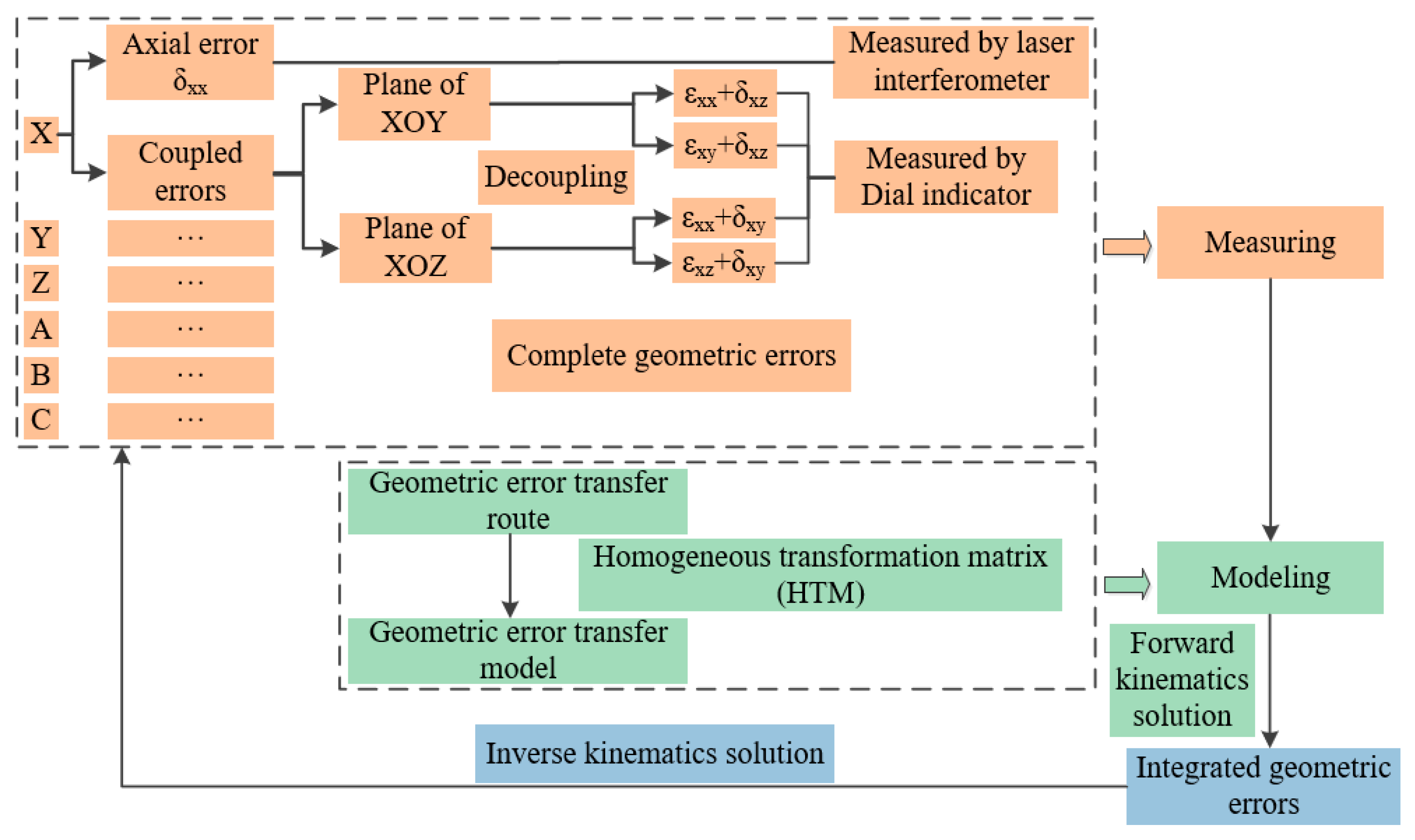
Figure 1. Flow chart of the coupling and decoupling measurement method.
Applsci 10 02164 g001
Figure 2. Complete geometric errors of the X-axis and the A-axis.
Applsci 10 02164 g002
Figure 3. Measurement of axial geometric displacement errors δxx.
Applsci 10 02164 g003
Figure 4. Measurement points on the X-axis and the A-axis.
Applsci 10 02164 g004
Figure 5. Geometric error coupling of the X-axis.
Applsci 10 02164 g005
Figure 6. Geometric error decoupling of the X-axis.
Applsci 10 02164 g006
Figure 7. Geometric error measuring and decoupling on the XOZ plane of the X-axis.
Applsci 10 02164 g007
Figure 8. Complete geometric errors of the X-axis and the A-axis.
Applsci 10 02164 g008
Figure 9. Coupling error measuring of the A-axis.
Applsci 10 02164 g009
Figure 10. Multi-axis machine tool that was investigated.
Applsci 10 02164 g010
Figure 11. Decomposition of the geometric error transfer route.
Applsci 10 02164 g011
Figure 12. Geometric error transfer route.
Applsci 10 02164 g012
Figure 13. Machining points to be calculated.
Applsci 10 02164 g013
Figure 14. Integrated geometric errors of machining points (3D view).
Applsci 10 02164 g014
Figure 15. Integrated geometric errors of machining points measured by the ball bar test (2D view).
Applsci 10 02164 g015
Table 1. Geometric errors of multi-axis machine tools.
X-AxisY-AxisZ-AxisA-AxisB-AxisC-Axis
Displacement errorsδxxδyxδzxδAxδBxδCx
δxyδyyδzyδAyδByδCy
δxzδyzδzzδAzδBzδCz
Angle errorsεxxεyxεzxεAxεBxεCx
εxyεyyεzyεAyεByεCy
εxzεyzεzzεAzεBzεCz