Abstract
In the global machining industry, ultra-precision/ultra-high-speed machining has become a challenge, and its requirements are getting higher and higher. The challenge of precision grinding lies in the difficulty in ensuring the various dimensions and geometric accuracy of the final machined parts. This paper mainly uses the theory of a multi-body system to propose a “double accuracy” theory of manufacturing and measurement. Firstly, the grinding theory with an accuracy of 0.1 μm and the precision three-coordinate measuring machine theory with an accuracy of 0.3 μm are deduced. Secondly, the two theories are analyzed. Aiming to better explain the practicability of the “double accuracy” theory, a batch of motorized spindle parts is processed by a grinding machine. Then the precision three-coordinate measuring machine is used to measure the shape and position tolerances such as the roundness, the squareness, the flatness, and the coaxiality. The results show that the reached roundness of part A and B is 5 μm and 0.5 μm, the squareness is 3 μm and 4.5 μm, and the coaxiality tolerance is 1.2 μm, respectively.
1. Introduction
Accuracy has always been one of the main goals of today’s manufacturing technology. Grinding accuracy directly affects the quality of the workpiece. Therefore, some scholars worldwide are committed to the research of geometric precision control, machine tool spindle error test, grinding precision monitoring, and other aspects in the grinding process [1,2,3]. Aiming to control the geometric accuracy of high-speed grinding, Jiang-nan Liu et al. [4] proposed a geometric accuracy analysis and design method. According to the specific structure of a three-axis numerical control surface grinder, an aging error propagation model including 21 parameters and a cost-quality model of key geometric error variables are established. It is proved that the model has good prediction accuracy. Atsushi Sato et al. [5] proposed a constraint-force controller based on algebraic equations, which has the ability to realize force control without time delay. Through analysis and derivation, the relationship between contact force and grinding resistance is used to control grinding force and improve grinding accuracy. At present, the rotation accuracy measurement method of the machine tool spindle has developed very maturely. However, as a kind of finishing, the grinding spindle usually has high precision, which makes it difficult to measure by traditional methods. Rahul R. Chakule et al. [6] used response surface methodology (RSM) to carry out experimental research on horizontal surface grinder. In addition, the evaluation of grinding performance parameters such as friction coefficient, cutting force, temperature and specific grinding energy under different processing environments is also discussed. The surface roughness and friction coefficient of MQL grinding are the lowest, which are 0.1236 μm and 0.3906 μm respectively, while the specific grinding energy of wet grinding is the lowest, which is 18.95 N/mm2. The temperature of MQL grinding is 29.07 °C, which is slightly higher than that of wet grinding. At the same time, the measurement technology of high-precision ultra-precision shaft and the rotation error separation technology have been hot topics in recent years. Liu Shutao et al. [7] introduced a new concept on the basis of the common separation methods of roundness error and rotation error of spindle, put forward the idea of secondary separation of rotation error, and established the mathematical model of this method. In order to solve the harmonic suppression problem of the three-point error separation technology, Cappa S. et al. [8] optimized the installation angle of the sensor. The common optimization method adopted is to maximize W (k). Ferreira FI et al. [9] proposed a method to predict the width of the dresser using indirect monitoring method. Acoustic emission signals are collected during the trimming process, and the width of the trimmer is correlated with the processed signal by using the estimation neural network to estimate the current value of the width. Using the program, an automatic system will be generated to readjust the dressing parameters while avoiding stop, reducing cost and improving grinding accuracy. Zhang Ya-Nan et al. [10] studied the grinding force and the material of the machined parts and obtained the correlation between the grinding force and the material. At the same time, the exploration of machine tool accuracy has also introduced acoustic emission monitoring technology, and it has become a hot topic in the field of advanced processing. Acoustic emission technology has been used for on-line monitoring of grinding processes such as end grinding [11], cylindrical transverse grinding [12], centerless grinding [13], etc. However, most of the authors have neglected the most important step in ensuring the precision of parts while studying the frontier of grinding precision technology. That is the accuracy of the machine tool itself and the testing accuracy of parts. In view of the accuracy of machine tools, many authors have also studied it. For example, Zhong Gaoyan et al. [14] have optimized and improved the structure of the machine tool, thus improving the cutting speed, machining accuracy, and machining efficiency. Qin, Haojie et al. [15] proposed a workpiece pose optimization method for a robot milling system to improve quasi-static performance and machining accuracy in the machining process. The above authors’ research has its merits. In this article, the precision of machine tools will be studied from another angle, and a “double accuracy theory” is proposed. The “double accuracy theory” is mainly based on the multi-body system theory for secondary analysis. Firstly, the coordinate system of the grinding machine and the precision three-coordinate measuring instrument is analyzed. Secondly, the grinding machine is used to process a batch of motorized spindle parts, and three-coordinate detection is carried out to detect their related shape and position errors. Finally, by analyzing the data, the accuracy error value is obtained, and the cause of the error is analyzed.
2. Theoretical Analysis of Grinding Machine Accuracy
Before analyzing grinding machine accuracy, multi-body system theory must be introduced for analysis [16]. The grinding machine itself is a multi-body mechanical system. Multi-body system theory is the basic theoretical basis for studying multi-body systems. It has good systematics and versatility and has been effectively applied in motion analysis of complex mechanical systems such as robots, coordinate measuring machines, machine tools, etc. Using multi-body system theory to analyze the errors of machine tool process system can not only meet the needs of machine tool error research, but also continuously expand the application field of multi-body system theory [17]. The topology description methods of multi-body systems mainly include direct path method, correlation matrix method and low-order body array method [18]. Compared with other methods, the low-order volume array method has simpler expression and higher computational efficiency and is currently a commonly used description method [19]. The type of grinding machine to be analyzed in this paper is Kellenbergaer universal high accuracy grinding machine from Switzerland, and its grinding accuracy is 0.1 μm. In the later part of the article, this grinding machine is also used for processing. The multi-body system diagram of the grinding machine after labeling is shown in Figure 1.
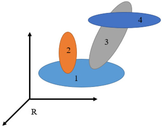
Figure 1.
Multi-body system diagram of grinding machine.
According to Figure 1 and the structure of Kellenbergaer universal high-precision grinding machine, it is divided into four moving bodies. These four moving bodies are respectively represented: grinding machine bed, C-axis and guide rail components, B-axis and grinding wheel rotating components. At that same time, as can be seen from Figure 1, each object has at least one adjacent low order body. If B0 is the lower order number object of B1, let Bj be any typical body in the multi-body system, and define Bi as the n-order lower order body of Bj, then there are:
When body Bj and body Bi are adjacent low order bodies, there is:
In the meantime, the N-order low-order matrix column of Bj defined according to Figure 1 is shown in Table 1.

Table 1.
Grinding machine multi-body system low sequence body array.
According to Table 1, the low-order body array of the multi-body system topology can connect the individuals in the multi-body system. For any object in the system, it can be traced back to the base coordinate system through the array, so it is widely used in practice. Meanwhile, the Kellenbergaer grinding machine is decomposed into motion coordinate system, and its purpose is to obtain the motion mathematical model of the grinding machine, so as to analyze the geometric error of the grinding machine and carry out comprehensive modeling. The grinding machine motion coordinate decomposition is shown in Figure 2.
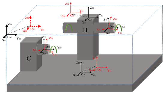
Figure 2.
Exploded view of grinding machine motion coordinate system.
According to Figure 2, the Kellenbergaer grinding machine can be equipped with three grinding wheels on the B axis in the figure. One of the grinding wheels is driven by a motorized spindle with a maximum rotation speed of 60,000 r/min. The B axis can rotate 360 degrees and move back and forth; the C axis is the workpiece axis; and the C axis can move left and right along with the guide rail.
According to Figure 2, coordinate system is the coordinate system of grinding machine, guide rail movement, C-axis rotation, B-axis movement, and B-axis rotation, respectively. Let the new coordinate system after the translation displacement of coordinate system along its own coordinates X axis, Y axis, and Z axis is be , respectively. Then the translation change matrix :
Similarly, the coordinate system is obtained by rotating coordinate system around Y axis to obtain coordinate system respectively. Then the change matrix is:
In the geometric error of grinding machine, the grinding wheel coordinate system and the workpiece coordinate system will not coincide, so the transformation matrix of relative to is the basic comprehensive error matrix:
Among them, the upper left corner mark E1 represents the transformation matrix between the corresponding two coordinate systems of the grinding machine under the condition of error.
Likewise, when represents the moving distance X of coordinate system , when the rotation angle of coordinate system and coordinate system is obtained, the relationship between coordinate system is obtained. Therefore,
By the same token:
Of which
is the translation error of Y axis.
is the translation error of the X axis.
is the angle error of the B axis in the X and Y directions;
is the angle error of the C axis in the x and y directions.
is the translation error of the B axis;
is the translation error of the C axis.
According to the above analysis and considering all geometric errors of the grinding machine, the comprehensive precision mathematical model is obtained:
Since the calculation formula is too large, simplify the labeling Equation (11) respectively. Please refer to the Appendix A for details of calculation.
3. Accuracy Theory of Precision Three-Coordinate Measuring Instrument
For the accuracy analysis of the precision three-coordinate measuring instrument, this paper mainly analyzes the equipment based on Laitz Infinity product, and its measurement accuracy is 0.3 μm. The coordinate system of the simple measuring instrument is shown in Figure 3.
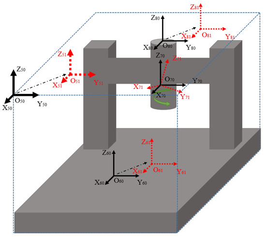
Figure 3.
Coordinate System of Three-coordinate Measuring Instrument.
As shown in Figure 3, coordinate system is respectively an integral coordinate system, a worktable translation coordinate system, a measuring probe rotation coordinate system and a measuring beam translation coordinate system. According to the theoretical solution method of grinding machine precision, it is also concluded that:
As mentioned in the following article and limited by space, the calculation results will not be given here.
4. Double Accuracy Theoretical Analysis
According to the accuracy theory of grinding machines and the accuracy theory of three-coordinate measuring instruments, as well as Equations (11) and (12), a “Double Accuracy Theory” can be introduced. This theory is mainly based on the error caused by a complete workpiece from processing to measurement. Since this is ultra-precision machining, each geometric error of the machine tool is very small. According to the small error assumption theory, the “Double Accuracy” simplified comprehensive accuracy error is obtained:
According to Equation (13) and Figure 2 and Figure 3, this is verified by error model. In grinding, it is assumed that only the B axis moves in translation. In the detection, it is assumed that only the crossbeam of the three-coordinate measuring instrument moves left and right along the Y direction. The rest of the axes are stationary. That is, there is only the error with the translation of the B axis of the grinding machine and the Y direction of the beam of the measuring instrument, and the rest of the error terms are zero. The calculation results are as follows:
Meanwhile, when only the errors of the above two motions are considered, Equation (14) is obtained. Assuming that other motions are considered, and some static states are taken into account, the corresponding calculation results of the comprehensive model are obtained. Next, it will be analyzed through experiments.
5. Experimental Analysis
5.1. Experiment of Cylindrical Grinding
Through the above theoretical research, experimental analysis was carried out and is described in the following. The machined workpiece is a certain type of motorized spindle. Motorized spindles are widely used, especially in the field of aerospace. Motorized spindles are needed for ultra-high speed or ultra-precision machining to improve the dimensional accuracy and surface roughness of parts. Important form and position tolerances of parts processed in this test are marked as shown in Figure 4.
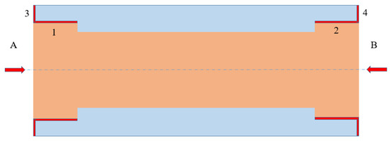
Figure 4.
Marking diagram of shape and position tolerance of motorized spindle.
Motorized spindle processing belongs to ring parts processing. As shown in Figure 4, the inner bore surface 1 and the inner bore surface 2 require roundness tolerance and cylindricity tolerance of 2 μm and 6 μm respectively; The flatness tolerance and verticality tolerance of end face 3 and end face 4 are 2.5 μm and 15μm, respectively. Therefore, this is a precision machining, which is carried out by using a Swiss Kellenbergaer grinding machine with a machining accuracy of 0.1 μm. Before machining the hole, semi-finish machining should be carried out on the outer circle to facilitate machining the inner hole as a positioning reference. The actual processing is shown in Figure 5.
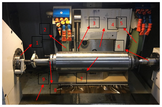
Figure 5.
Actual machining site of motorized spindle. 1—workpiece C axis; 2—cylindrical grinding wheel; 3—ruby probe; 4—axis B; 5—30° end face grinding wheel; 6—tailstock; 7—motorized spindle part; 8—tooling fixture; 9—guide rail.
According to Figure 5, the processing site is shown and analyzed in conjunction with Figure 2. This processing uses Swiss Kellenbergaer grinding machine for processing, and the processing accuracy is 0.1 μm. In machining, 90° outer circular CBN wheel, 30° CBN end face wheel and CBN inner hole wheel are used. The grinding machine is divided into B-axis and C-axis, and 5 coordinate systems move. The outer circle and the end face are machined by the B axis, and the B axis can rotate 180 degrees. The other end of the B shaft is equipped with a motorized spindle with a maximum rotation of 80,000 r/min; It is mainly used to process inner holes. Because the surface of the inner hole of the processed parts requires very high geometric error, this motorized spindle is used to process the inner hole. In order to get more preparation for the machining errors, 6 motorized spindles were machined and analyzed. The finished motorized spindle is shown in Figure 6.
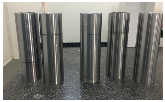
Figure 6.
Drawing of 5 finished motorized spindles.
5.2. Precision Three Coordinate Measurement Analysis
Aiming to check whether the precision of the processed six motorized spindles meets the requirements of parts, high-precision inspection must be carried out. In this paper, Laitz Infinity three-coordinate measuring instrument is used for detection, and the detection accuracy of the equipment is 0.3 μm. The parts to be detected are shown in the red mark in Figure 4. The test site is shown in Figure 7.
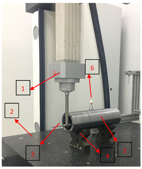
Figure 7.
Inspection site of motorized spindle. 1—telescopic probe; 2—workbench; 3—probe; 4—V block; 5—motorized spindle part; 6—school team coordinate system.
According to Figure 7, both ends of the detection workpiece are respectively supported by precision V-shaped blocks, and then the red part of Figure 4 is respectively operated with probes and detected. The probe is made of ruby sensitive material. In the process of detection, the circumference scanning path method and capture positioning method are adopted for measurement. The circumferential scanning path method mainly detects the coaxiality and roundness errors between the inner hole and the outer circle. The capture and positioning method mainly measures the runout error of the workpiece end face and the length error of the part. The red parts 1 and 2 in Figure 4 are respectively detected three times at different places, and the two ends are detected. By processing the detection data, Figure 8, Figure 9 and Figure 10 are obtained, respectively. The final detection accuracy error values are shown in Table 2.

Figure 8.
Data diagram of three tests at end A of workpiece. (A) First test; (B) second test, and (C) third test.

Figure 9.
Three-time test data diagram of workpiece B end. (A) First test, (B) second test, and (C) third test.
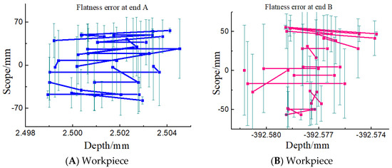
Figure 10.
Plane test data diagram of workpiece (A) and (B).

Table 2.
Detection accuracy error table.
According to the three-time detection process shown in Figure 8, the error ranges of the three-time runout are 14 μm, 6 μm, and 6 μm, respectively. At the same time, in Figure 9, the error runout range is detected three times: 6 μm, 8 μm, and 10 μm. This linear error change is mainly due to the fact that the workpiece is clamped by a double-top clamping method. The expansion sleeve has a certain outward expansion tension, which maximizes the error between the two sections of the workpiece. From Figure 10, it is concluded that the A-plane error range is around 7.2 μm. The B-plane error is around 8.4 μm. According to the test results in Table 2, the roundness of A and B are 5 μm and 0.5 μm, respectively; the verticality is 3 μm and 4.5 μm, respectively; the flatness is 7.2 μm and 8.4 μm respectively; and the coaxiality is 1.2 μm, respectively. At the same time, in the inner hole surface detection, the latter one is always higher than the previous one. This mainly shows that the accuracy of the outer circular surface is always lower than that of the surface close to the rotation position of the workpiece shaft during machining. Once again, it can be seen from the coaxiality of the A end face and the B end face that the coaxiality error difference between the A end face and the B end face is 0.0294 mm. Through the following analysis, the main reason for this is the accuracy of tooling and fixture, the size of grinding wheel abrasive particles, and the processing technology. Simultaneously, reviewing reference [4] and reference [10], a clear mapping relationship has been formed. With the precision theory and multi-body system theory put forward in reference [4], 21 parameters are used to model and study the machining geometric precision, thus analyzing the grinding precision. The established model can guide the tolerance distribution of grinding parts to achieve the purpose of prediction accuracy. The relationship between grinding force and grinding material was proposed in reference [10]. The relationship between the grinding wheel abrasive particle size and grinding parameters in this paper is also reflected. However, it is mentioned in this paper that the grinding accuracy is also related to the measurement accuracy. It is comprehensively explained that there are many factors that affect the grinding accuracy in ultra-precision grinding.
6. Conclusions
- (1)
- For the multi-body system theory, the “double accuracy” theory is proposed in this paper. Firstly, the spatial coordinate system of grinding machine and three-coordinate measuring instrument is established, and the precision theory of grinding machine and three-coordinate measuring instrument is analyzed. Secondly, the two theories are combined for analysis and theoretical verification of the model.
- (2)
- Aiming to better explain the “double accuracy” theory, experiments are carried out in the article to prove that through the machining of the motorized spindle, the Swiss high precision grinding machine is used for fine grinding, and the machined motorized spindle is detected. At the same time, the shape and position tolerances, such as roundness, verticality, end face flatness and coaxiality, are obtained. Showing from the results, the main reason for the change of two-stage linear error lies in the fact that the workpiece is clamped by a double-top clamping method. The expansion sleeve has a certain outward expansion tension, which maximizes the error between the two sections of the workpiece. The roundness of A and B is 5 μm and 0.5 μm, respectively; the verticality is 3 μm and 4.5 μm, respectively; the flatness is 7.2 μm and 8.4 μm, respectively; and the coaxiality is 1.2 μm, respectively. At the same time, the coaxiality error difference between the two ends of the motorized spindle is analyzed to be 0.0294 mm. The main reason for this is the accuracy of tooling and fixture, the size of grinding wheel abrasive particles and the processing technology.
- (3)
- The research of this method not only theoretically expounds the precision relation between grinding and subsequent measurement, but also actually analyzes the causes of the errors and the areas that need improvement in the future. At the same time, the differences with the existing research results are analyzed, which lays a theoretical and experimental foundation for similar processing analysis.
Author Contributions
Supervision, L.H.; conceptualization, L.H. and Y.C.; research methodology, L.H. and J.Z.; experimental operation, L.H. and Y.L.; writing—review and editing, L.H. All authors have read and agreed to the published version of the manuscript.
Funding
This research was funded by [National Science and Technology Major Project of the Ministry of Science and Technology of China] grant number [2018ZX04002001]. And The APC was funded by [2018ZX04002001].
Acknowledgments
This project is supported by the National Key Research and Development Program of China (2018YFB2000502) and the National Science and Technology Major Project of the Ministry of Science and Technology of China (2018ZX04002001) and the National Science and Technology Major Project (2017-VII-0001-0094).
Conflicts of Interest
The authors declare no conflicts of interest.
Appendix A
Extended Calculation of Equation (11).
References
- Smirnov, V.A.; Repko, A.V. Workpiece temperature variations during flat peripheral grinding. Manag. Syst. Prod. Eng. 2018, 26, 93–98. [Google Scholar] [CrossRef]
- Fan, J.; Wang, H.; Tang, Y. Error modeling and identification technology for a CNC camshaft grinder. J. Vib. Shock 2017, 36, 257–264. [Google Scholar]
- Qu, D.; Ding, F.; Zhou, Z.Q.; Xue, J.D.; Wang, B. Experimental study on grinding the micro wall of flexible joints with controllable force. Int. J. Adv. Manuf. Technol. 2017, 89, 1485–1494. [Google Scholar] [CrossRef]
- Liu, J.; Hong, Y. Analysis and robust design of geometric accuracy of a three-axis CNC surface grinding machine. Hong Kong J. Soc. Sci. 2016, 4, 43. [Google Scholar]
- Sato, A.; Shen, K.; Minami, M.; Matsuno, T. Improvement of force-sensorless grinding accuracy with resistance compensation. Artif. Life Robot. 2017, 22, 509–514. [Google Scholar] [CrossRef]
- Chakule, R.R.; Chaudhari, S.S.; Talmale, P.S. Evaluation of the effects of machining parameters on MQL based surface grinding process using response surface methodology. J. Mech. Sci. Technol. 2017, 31, 3907–3916. [Google Scholar] [CrossRef]
- Liu, S.; Yang, P.; Kang, H. Secondary separation technology of spindle rotation error based on three-point method. Manuf. Technol. Mach. Tool 2008, 112–115. [Google Scholar]
- Cappa, S.; Reynaerts, D.; Al-Bender, F. A sub-nanometre spindle error motion separation technique. Precis. Eng. 2014, 38, 458–471. [Google Scholar] [CrossRef]
- Ferreira, F.I.; de Aguiar, P.R.; Lopes, W.N.; Rossinoli Martins, C.H.; de Souza Ruzzi, R.; Bianchi, E.C.; D’Addona, D.M. Inferential measurement of the dresser width for the grinding process automation. Int. J. Adv. Manuf. Technol. 2019, 100, 3055–3066. [Google Scholar] [CrossRef]
- Zhang, Y.-N.; Lin, B.; Liu, J.-J.; Key, J.Y. An experimental study on mechanical modeling of ceramics based on microstructure. Appl. Sci. 2015, 5, 1337–1349. [Google Scholar] [CrossRef]
- Han, X.; Wu, T. Analysis of acoustic emission in precision and high-efficiency grinding technology. Int. J. Adv. Manuf. Technol. 2013, 67, 1997–2006. [Google Scholar] [CrossRef]
- Jiang, C.; Li, H.; Mai, Y.; Guo, D. Material removal monitoring in precision cylindrical plunge grinding using acoustic emission signal. Proc. Inst. Mech. Eng. Part C. J. Mech. Eng. Sci. 2013, 228, 715–722. [Google Scholar] [CrossRef]
- Kim, H.Y.; Kim, S.R.; Ahn, J.H.; Kim, S.H. Process monitoring of centerless grinding using acoustic emission. J. Mater. Process. Tech. 2001, 111, 273–278. [Google Scholar] [CrossRef]
- Zhong, G.; Liu, P.; Mei, X.; Wang, Y.; Xu, F.; Yang, S. Design optimization approach of a large-scale moving framework for a large 5-axis machining center. Appl. Sci. 2018, 8, 1598. [Google Scholar] [CrossRef]
- Qin, H.J.; Li, Y.; Xiong, X. Workpiece pose optimization for milling with flexible-joint robots to improve quasi-static performance. Appl. Sci. 2019, 9, 1044. [Google Scholar] [CrossRef]
- Xing, Y.; Zhang, L.; He, B.; Wang, S. Precision reverse design of numerical controlled (NC) machine on the basis of multibody theory. Nongye Jixie Xuebao/Trans. Chin. Soc. Agric. Mach. 2014, 45, 282–287. [Google Scholar]
- Su, S.; Li, S. A study on prediction modeling of machining accuracy for CNC machine tools. ICPN 2002, 2, 123–127. [Google Scholar]
- Liu, Y.; Zhang, Y. Thermal error compensation technology for machining centers based on multi-body theory model. J. Mech. Eng. 2002, 38, 127–130. [Google Scholar] [CrossRef]
- Wang, W.; Yang, J.; Yao, X.; Fan, F.; Li, Z. Comprehensive modeling and real-time compensation of geometric error and thermal error of numerical control machine tools. J. Mech. Eng. 2012, 48, 165–170. [Google Scholar] [CrossRef]
© 2020 by the authors. Licensee MDPI, Basel, Switzerland. This article is an open access article distributed under the terms and conditions of the Creative Commons Attribution (CC BY) license (http://creativecommons.org/licenses/by/4.0/).