1. Introduction
In previous generations of mobile systems and networks (2G/3G), a special emphasis has been placed in the radio domain on the development of distributed radio access network (D-RAN) architecture. It consisted in the fact that devices processing signals in the baseband (BB), intermediate-band (IF), and radio-frequency-band (RF) were located near to the mast with the antennas. The significant increase in the demand for signal processing, especially in the baseband, meant that we had to look for different solutions. Existing terminal devices, called base stations, can no longer be developed in the traditional way, because they would have to be supercomputers with high computing power in a moment (with high network traffic), and in other cases idling equipment (e.g., with a negligibly small nighttime traffic) that would have to be turned off to save energy without the use of their computational potential. The solution to this problem is to transfer computing functions into the network so that the computers performing these operations may be used for other purposes in the absence of mobile network traffic. This requires central control architecture of remote radio modules whose functions are as limited as their physical equipment allows.
In the future Next Generation Radio Access Networks (NG-RANs) domain of the 5G systems, exactly centralized/cloud control technology (C-RAN) will be widely used with a large set of gNodeB (gNB) base stations that will also be working in distributed structures/architectures (not to be confused with D-RAN).
1.1. State-of-the-Art 5G C-RAN Solutions
The basic concept in the NG-RAN domain, which is promoted by 5GPPP, is the multi-layered architecture of XHaul [
1,
2]. This solution is based on an optical network that is designed to support traffic from various Split/Option interfaces. This architecture also includes D-RAN solutions, which means joint support for management of traffic from the fronthaul and backhaul. Based on this solution, the authors of publications [
3,
4,
5] proposed network architectures based on optical and microwave (radio-line) transport. The presented solutions introduce traffic optimization, which, however, does not take into account the possibility of transmitting signals occurring in the A-RoF format in the network. The architecture of an Optical Transport Network (OTN) system is prepared for an efficient transport of digital traffic, which is provided at client access points. The situation is similar in the case of Time Shared Optical Network (TSON), which is a very good solution supporting the transport of information from radio-over-Ethernet (RoE) (enhanced common public radio interface (eCPRI) as well as next generation fronthaul interface (NGFI)) interfaces. A lot of research and development have been devoted to various optimization solutions for transportation systems of streams from D-RoF interfaces. The author reviewed the available studies [
6,
7,
8,
9,
10,
11,
12,
13], which contained the results of studies showing the undoubted legitimacy of using the D-RoF technique. In these studies, particular emphasis was put on showing that a particular type of Split/Option or method of digitizing a radio signal to a bit form gives the opportunity to increase a link efficiency. There is no difference in the selection of the Split/Option method in the context of the load on the fronthaul network or the RRH unit. In special solutions, attempts were made to use compression methods when processing from analog to digital [
14]; which, however—with a very large number of digital streams delivered to RRH working in massive-MMIO format—will not bring much efficiency. There remains the A-RoF solution with the least research, especially for 5G C-RAN applications. The papers [
15,
16,
17,
18,
19] show a focus on specific solutions, which consist in conducting experiments documenting that radio signals in the BB, IF, and RF bands can be transmitted in optical fiber paths. These solutions were already tested many years ago. Several books have also been written on this subject [
20,
21]. In each of the presented experiments, however, no attention was paid to what generation of optical fibers will be used and to what extent future xWDM networks can be used to transport de facto analog signals. Particular attention of the author was caught by the study [
22], which indicates the next field of activity, where the use or disposition of an optical fiber of the appropriate generation, located in the optical path, can be decisive in the selection of the radio signal transport system in its original form.
1.2. Author’s Contribution
The solution of the combined approach to the analysis of the needs of the A-RoF and D-RoF interfaces was not undertaken in the above-mentioned studies. The author proposed the coexistence of these interfaces in an optical network. This task is possible when the fiber optic RAN network is all-optical. Of course, we can use fiber-to-the-antenna (FFTA) or passive optical network (PON) architecture, but passive solutions do not provide such a wide scale of optical resource management. Implementation of the network in the XHaul architecture enables the transport of digital data (backhaul) and digitized signals (fronthaul—D-RoF). The combination of A-RoF and D-RoF traffic forces proper preparation of all nodes in the network from the NG-RAN domain. Therefore, the author proposed a special O-RRH construction that can be directly or through-connected to a all-optical network. This construction was first presented by the author at an optical conference in Prague [
23]. This also applies to BBU and DU nodes, which by definition have adequate computing power and will perform most of the tasks on a software basis. The method of managing nodes that carry also A-RoF traffic was presented by the author at the fiber-optic conference in Suprasl [
24]. In addition, in order to formalize the baseband-over-fiber (BBoF), intermediate-frequency-over-fiber (IFoF) and radio-frequency-over-fiber (RFoF) solutions, it was proposed to extend the function of the Option 8 and to introduce new Options 9 and 10 in relation to the 3GPP model. The most important component of the author’s study are unique calculations that indicate the need to reserve optical resources when transporting digital streams from the D-RoF (CPRI, eCPRI) and A-RoF (BBoF, IFoF and RFoF) interfaces. Calculations were made for a variable width of radio channel according to the 5G-NR-Rel-15 baseband (CP-OFDM waveform). The results of the calculations can be of major application when scaling the resources of an all-optical network, whose task will be to transport any type of signal, including A-RoF. The calculation formulas presented below have been adapted to 5G modulation and code solutions or created from scratch as a result of appropriate transformations (applies to A-RoF interfaces). It should be noted that the effectiveness of the presented approach to handling A-RoF and D-RoF traffic will be leading when introducing O-RRH working in massive-MIMO format, where we will have to deal with handling large traffic from a large number of EUs (need to introduce IoT, which will be supported in the wireless part by 5G systems). The results of the calculations carried out will allow efficient decision-making about switching the connection to the selected type of options in the extended range by the author, i.e., Options 1–10.
1.3. NG-RAN Concept Description
The distributed architecture of the gNB base station makes it possible to surround the user equipment (UE) and thus more efficient management of spatial resources. This task is accomplished through the use of wideband and flexible all-optical networks based on the Dense Wavelength Division Multiplexing (DWDM) system with a flexible grid of optical channels [
25] or new more flexible Elastic Optical Networks (EON) [
26] working with the Ultra-Dense Wavelength Division Multiplexing (UDWDM) format and extra flexible reconfigurable transponders. The optical network is so versatile that it can be used to transmit information/signals both in the area of the backhaul (BH) as well as the fronthaul (FH)/midhaul (MH) of the future next generation mobile systems.
The purpose of the backhaul (inside the cloud in
Figure 1) is to connect the next generation core (NGC/5GC) with the NG-RAN control units through the gNB-central units (gNB-CUs). The fronthaul is used in creation of fast and often synchronous links between the gNB-CU and components of the distributed 5G base stations, i.e., gNB-distributed unit (gNB-DU)—
Figure 1 [
27]. The architecture of the distributed NG-RAN occurs in two concepts, i.e., based on the fronhaul network (
Figure 1a) and with the division of the distribution network on the fronthaul and midhaul—
Figure 1b. The second concept indicates the possibility of using a distribution point/unit (DU), whose task will be to perform some activities related to local signal processing and their distribution to functionally limited network termination units such as active antenna unit (AAU)/remote radio unit (RRU)/remote radio head (RRH).
Inside the gray cloud in
Figure 1, there are a 5G-NGC network and a set of gNB-CU/ baseband unit (BBU) cooperating with each other. The method of cooperation between central units processing the radio signals symbolizes additional terms such as ‘cloud’ and ‘hotel’. The term ‘cloud’ means that individual units can be located at a greater distance in separate buildings, which forces them to use quick connections with small delays. The term ‘hotel’ (alternatively often used as ‘pool’) symbolizes the placement of units in the same building, which is equivalent to a physical signal processing center, while BBUs/CUs are usually separated in distributed logical structures, which are managed by the so-called virtual machines.
From now, in order to simplify further description of the functioning of the network components, we will call the control units generally gNB-CU/BBU, and devices controlled by abbreviation gNB-DU/RRH. The name of the DU nodes that define the boundary between the F1 and F2 interfaces (
Figure 1) will remain unchanged.
The fiber-optic FH can be a passive component (FTTA or PON) of the C-RAN, which is applicable in mobile networks of current generations (2G/3G/4G). The demand for more and more bandwidths in the backhaul networks forces the optimization of fiber network resources, which is why it is necessary to pay attention to the previously mentioned active flexible optical networks [
25,
26] using WDM technique.
The WDM technique enables the simultaneous transmission of several optical signals (different frequency channels) in one fiber-optic link or one optical path. Fiber-optic link is understood as a connection between nodes of the network, and the optical path is the path on which the optical signal travels passing through the optical nodes. Fiber-optic links are implemented using single-mode silica fibers, where single-modality is maintained for wavelengths in the range of 1260–1675 nm. An optical node determines whether a fiber-optic network can be called all-optical. If a node does not go to the electronic level (on the user’s layer), to regenerate the signal or to reorganize the digital data, then this node can be called all-optical. Such nodes include optical add-drop multiplexer (OADM) or reconfigurable OADM (ROADM), as well as photonic cross-connects (PXCs). Of course, the process of signal regeneration can take place in all-optical nodes, but it must be implemented on the optical layer, which is currently extremely expensive (the need for precise recognition of the signal modulation format). ROADM and PXC are usually adapted to the so-called optical grids according to the standards defining transport systems. Optical channel grids, on the other hand, are adapted to the optimal parameters of optical fibers connecting nodes. In this case, it concerns the optical ranges of the S, C, L, and U bands [
1]. If we release from these nodal devices the permanent set of optical filters and internal constraints to xWDM grids, then we will get full flexibility. Unfortunately, this is done at the expense of a high increase in the demand for effective photonic resources management in each of these nodes. If an optical node is able to switch any channel (in a technologically limited range—any optical carrier wavelength and any optical channel width), then it is sensible to use different modulation formats, in addition to the classic on-off keying (OOK). As the optical channels are spectrally independent with appropriately selected optical path or link parameters, they can carry completely different signals, i.e., modulated in various formats. Therefore, the flexibility of the optical network using the WDM technique enables an effective combination of traffic, in one fiber-optic link, coming from functionally different networks. Separation of different streams in an optical link can be accomplished by assigning separate optical carriers. An active network, in which there are various signals, must also be equipped with flexible nodes and transponders [
26,
28], which will be able to recognize signals and place them in the appropriate space of the grid of a given xWDM system (elastic or static). This assumption forces, on the side of gNB-DU/RRH, the use of all-optical nodes and optical terminations of the C-RAN. Of course, this does not exclude the possibility of mutual communication of C-RAN radio devices via radio interfaces operating in the “sub-6” (FR1) and “mmWave” (FR2) bands [
29].
The following description presents the concept of integrated optical gNB-DU/RRH, that was presented by the author for the first time at the photonic conference in Prague [
23] as the optical RRH (O-RRH). The material concerning this concept is also included in this work for the sake of completeness as well as due to the introduction of minor changes regarding the adaptation of the radio-photonic unit to flexible optical networks.
Optical gNB-DU/RRH enables communication with gNB-CU/BBU by using non-standardized interfaces and modulations. Integration of an optical multiplexer with a radio module enables the ingress to the optical fronthaul, connecting gNB-CU/BBU and gNB-DU/RRH, signals originating not only from a digitized radio-over-fiber (D-RoF) interfaces [
30], i.e., common public radio interface (CPRI) [
31] or evolved CPRI (eCPRI) [
32], but also an analog radio-over-fiber (A-RoF) [
30].
On the side of the signal processing center gNB-CU, the situation looks a little bit different, because here we have a lot of power in terms of signal processing. The task of the central unit will therefore be to collect all physical resource blocks (PRBs) (in terms of time and frequency) directed to specific UE on the wireless side, combining into one or several channels from the baseband and inserting these channels into the IF or RF band using the direct digital synthesis (DDS). In case of the D-RoF format, the process will be terminated on the digitization of the channel created in the baseband. In order to create an A-RoF signal, the other signal processing steps mentioned above must be implemented.
The purpose of performed analyses and calculations, the results of which are presented in the following paper, is to show that the signals of D-RoF and A-RoF formats can be transmitted in the same all-optical network, using the proposed construction of gNB-DU/RRH with optical termination, as well as the indication of scenarios in which it makes sense to use interfaces working in the A-RoF formats as those that provide a high degree of wavelength band savings compared to the D-RoF interfaces, in the fronthaul/midhaul optical path setup between gNB-CU and gNB-DU/RRH.
The motivation of the conducted research follows from the fact that the expansion of the C-RAN architecture is inevitable; therefore, it is necessary to search for solutions that will simplify the functions performed by a set of antenna modules and then move many more functions to signal processing centers that will lease computing power.
2. Radio and Photonic Components in Optical Massive-MIMO gNB-DU/RRH
The NG-RAN built on the basis of all-optical solutions enforces the introduction of the network termination in the form of an integrated optical gNB-DU/RRH. In this way, the created active-distributed-antenna-system (A-DAS) network (
Figure 1) will enable solutions based on the spatial surrounding of the terminal by the so-called distributed gNB base station. The distribution of radio signals to/from gNB-DU/RRH via optical links will guarantee very high delay constancy, which in the situation of using digital beamforming (DBF) or hybrid beamforming (HBF) of radio beams directed to/from the UE is superior. An exception will occur in the case when the eCPRI interface is used, in which the synchronous ethernet (SyncE) technology is applied [
33,
34,
35], creating a RoE link [
36,
37]. Of course, the stream of Ethernet frames can be transported through optical transport network (OTN) links [
38], similarly to CPRI [
39], but in case of the need to enter on the layer 2 (L2), in order to switch frame streams, the optical path will be terminated. Here, the guarantee of low variance of delay may not be possible, unless the Ethernet switch is equipped with optical ports that are connected through the linear clock on the layer 0 (L0) (the optical layer determines the transferred clock step).
The Integrated Optical gNB-DU/RRH can exist in several configurations, what depends on the construction of the radio massive-multiple-input–multiple-output (massive-MIMO) head and the photonic module.
Figure 2 presents three types of optical gNB-DU/RRH, which are characterized by a four-sectors (a), one-sector (b) and six-sectors (c) radio head. Construction concepts (a) and (c) are very similar to each other, because they require the use of stepwise transfer of connections between sectors. In case (b), only one sector was used, which is equipped with, in proportion to other solutions, a large number of radio and aerial modules. The single-unit gNB-DU/RRH device will allow for smooth tracking through the UE radio beam around the mast. In this construction, it is required to smoothly switch off individual radio modules when the angle at which the UE terminal lies is exceeded. In each case shown (
Figure 2), gNB-DU/RRH is directly connected to a fiber-optic link (at least one pair of optical fibers) in which the xWDM technique is applied (signals in accordance with the DWDM system or OTN/EON type development). In solutions (a) and (c) in the photonic part, the microROADM was used, which indicates the possibility of using the device in a double optical ring, where we will have a reserve route and the possibility of dynamic management of the add/drop band. The single-sector solution gNB-DU/RRH is based on the equipping of the photonic side in microOM/microDM [
40,
41], which indicates that this type of device will be able to be placed at the physical terminal of the optical path/link. The optical mux (OM)/optical demux (OD) terminating the optical path/link may be also applied in the cases (a) and (c)—
Figure 2. This will depend only on the place where the gNB-DU/RRH device is connected to the optical network.
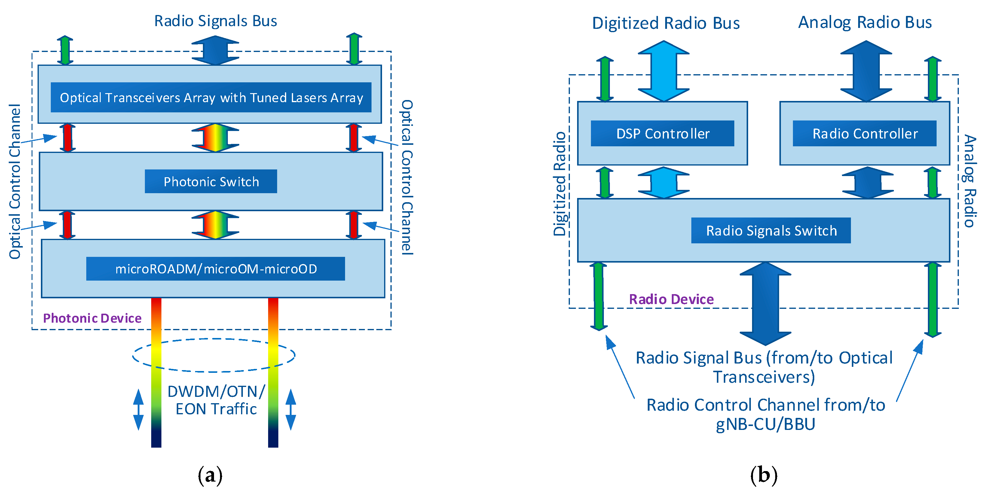
The two downstream devices (modules) in optical a gNB-DU/RRH are described in more detail in
Figure 3. The photonic switch (
Figure 3a) allows a local optical channel redirection, depending on the need to direct concentrated radio traffic to a specific part of the antenna module assembly (
Figure 4). A very important component is the array of media-converters (transceivers), whose task will be to shift from the photonic to the radio domain and vice versa. These systems will have to support signals modulated in D-RoF and A-RoF [
30] formats, so they will have to work in a flexible mode. The lasers built into these converters should be longitudinally single-mode and have the possibility of dynamic tuning. In addition to the optical and radio bus, along the radio-photonic module, a bus runs with a control channel (
Figure 3a, red—optical, green—electric), which was delivered as a dedicated optical channel from the controller working at the gNB-CU/BBU. Through this digital channel, we can control any component in the photonic and radio signal processing chain. Its function will primarily be to determine and establish the path on which radio frequencies from a specific radio band or baseband channels (in analog or digitized form) will travel.
Next block (
Figure 3b) is connected to an electric bus that has a large number of transmission lines. The number of transmission lines depends on the number of media converters included in the radio-photonic block. The transmission bus provides signals to the ports of the signal switch, whose task is to direct the appropriate signal for initial preparation or separation, before entering them to the specific radio antenna subunit. The digital signals go to the DSP controller, which demultiplexes/ multiplexes streams in the time domain and organizes them so that they reach the appropriate transmission line connecting with a specific radio-antenna module. The analog signals go to the radio controller, where they are pre-prepared (e.g., adaptation to the transmission line, correction of time and frequency parameters, or pre-amplification in a small range). The analog radio signal (A-RoF format) can come from the following ranges: BB, IF, or RF.
The control channel (
Figure 3 and
Figure 4—green lines) enables the radio block subassemblies to operate and continues along the radio signal transmission bus. The functionality of the control channel does not terminate there. It is still appropriate to control the final radio systems closest to the antenna array assembly—
Figure 4.
The digital and analog buses are routed from the radio module to the radio-antenna head. Along the head with antennas, attachments should be placed to individual units converting radio signals prepared for emission in places of antennas.
Digitized radio signals (
Figure 4) go to the digital block, where their duplex directions are subjected to separation and they are converted (processed) from digital to analog and vice versa. Here, there is an encoding/decoding operation for the partial streams that have reached the gNB-DU/RRH optical interface in CPRI/eCPRI format [
31,
32]. The signal from BB (uplink direction) gains its original form and is then transferred to the RF band. At this point, it is possible to use a greater number of the radio signal conversion degrees. It depends on the method of group transmission of baseband channels and the need for cooperation with analog signal transformation techniques. In the radio signal adaptation chain, there is also a section for forming the radiated beam. Each radio-antenna module is equipped with systems for two directions that allow analog beamforming and spatial beam control in cooperation with other radio-antenna modules. In the case when signals in a digitized form (prepared in gNB-CU/BBU) are delivered to the radio-antenna module, then DBF is additionally applied. The combination of these two techniques makes it possible to use hybrid solutions [
42,
43], which balances the load on the components of the fronthaul network and increase the precision of beam control on the free space side.
A single radio-antenna module must be equipped with a duplexer whose task is to separate and combine signals from different directions. The diplexers allow us to direct a specific radio band to the appropriate antenna dipole. Currently, diplexers are used as passive devices, but in the case of multi-band work (radio interfaces of next generations) of antenna array, we may need an active system, which will also be susceptible to control from the radio module or even gNB-CU/BBU.
The coupling of components shown in
Figure 3 and
Figure 4, through fast and multi-track buses, gives the possibility to build a through or path terminating the optical gNB-DU/RRH. The optical channels will mostly be scaled at the gNB-CU/BBU level, but these functions may be partially moved to the gNB-DU/RRH. The control method of optical massive-MIMO gNB-DU/RRH depends on the method of controlling the entire domain of devices operating in the FH or MH network. The presented proposal assumes C-RAN control with the possibility of distributing the signal preparation centers gNB-CU/BBU Hotel/Cloud (
Figure 1). From the radio termination point of the optical gNB-DU/RRH, despite the partially distributed network devices processing BB, IF, of RF signals (gNB-CU/BBU Cloud), gNB-CU/BBU nodes are seen as centrally located devices and communicate in parallel regarding the so-called gNB-CU/BBU clouds.
Figure 5 shows an example of a network where a cloud is located in the middle representing an evolved packet core (EPC)/next generation core (NGC), a network of software defined radio (SDR) devices (gNB-CU/BBU) and a central Open Flow (OF) controller [
44,
45] as a resource manager in the NG-RAN domain. The example network is based on the optical layer in the ring architecture, however, the logical structure of connections between NGC and gNB as well as gNB-CU/BBU and gNB-DU/RRH has tree architecture. Access to the optical network takes place through the so-called optical concentrators, i.e., optical multiplexers. The proposed gNB-DU/RRH have the built-in microROADM or microOM/microOD, which gives the possibility of their direct connection to the optical ring structure (microROADM case). If there is a need to connect the outside gNB-DU/RRH in the access mode (the so-called south direction), then it should have at least an optical multiplexer and demultiplexer (microOM/microOD case). The assumption that the network is all-optical requires the use of PXC or ROADM in nodes, which guarantees that there will be no conversion of the photonic to electric signal in these nodes and vice versa. Of course, this only applies to the transport of signals carrying user data (user plane).
The control layer using OF [
44,
45] must be organized so that all optical nodes together with gNB-DU/RRH and O-gNB remain under full control. As seen in the upper part of
Figure 5, the optical network can connect gNB-DU/RRH and O-gNB to the core of the packet network and the surrounding cloud of the gNB-CU/BBU modules. All that remains is to design a mechanism for flexible resource management, which will decide how the optical resources will look like when simultaneously (hybrid) serving all streams from NG-RAN. PXC nodes equipped with DU functions will deal with the distribution of optical streams that will transport radio signals with high time requirements (physical layer) to the appropriate gNB-DU/RRH, whose functions can be dynamically reduced to AAU (depending on the load of links in network and signal processing centers in the cloud). In the situation that the midhaul network (serving traffic with lower time requirements) does not exist (
Figure 1a), all the DU functions are taken over by gNB-DU. In this case, high time requirements are taken over by the network at the level of interface F1. The type of transport technology used (
Figure 6) in particular interfaces and links will depend heavily on the type of Split/Option and its requirements. It should be noted that each stream of L1, L2, and L3 layers can be transported through an active optical network, which in the all-optical version represents the so-called L0 layer (beside the 7-layer ISO/OSI model).
3. Simple Model of Bandwidth Consumption Calculation in 5G Fronthaul Interfaces
The efficiency of the FH and MH links is the basis for a properly functioning C-RAN (in 5G-NG-RAN) structure. Currently, the CPRI format [
31] is widely used in the links of fronthaul, the simplicity of which does not require using too large processing power from the signal processing systems, but the resulting streams are characterized by very high bit-rates. The demand for high CPRI bit-rate is primarily due to the need to connect to the gNB-CU/BBU cloud, independently, each antenna module (
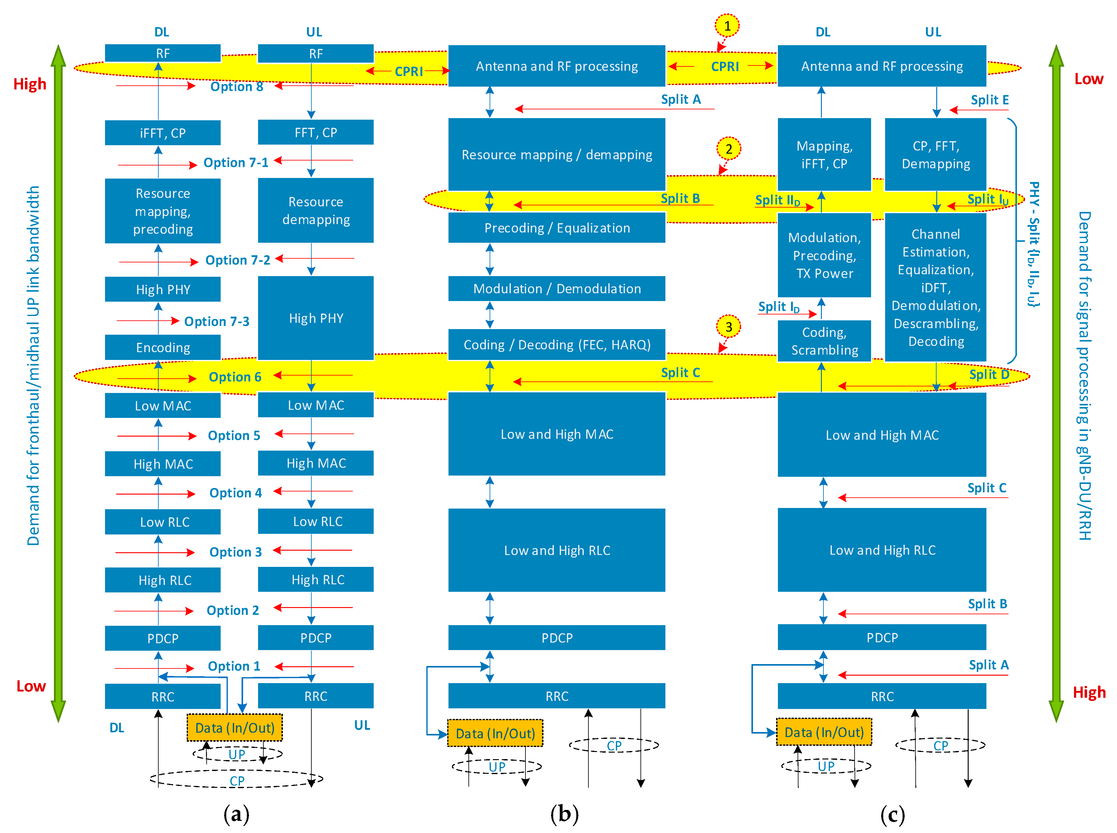
Figure 4) located in the radio-antenna head. In the Spits/Options model (
Figure 7), the CPRI interface is at the top, which means that this digital stream will be directed to gNB-DU/RRH with low processing power. The functionality of this network termination will be limited to AAU. Currently, we have defined the fastest optical interface CPRI v.7.0 [
31] with 24.3 Gbps. In many situations, especially when connecting the gNB-DU/RRH devices working in massive-MIMO format to fronthaul, the need for a larger number of the fastest CPRI streams is necessary. The introduction of faster bitstreams is pointless due to the emerging dispersal constraints of single-mode telecommunication optical fiber. In a DWDM network, we can concentrate more CPRI streams into one optical fiber, but with the dense location of the gNB-DU/RRH terminals, it is necessary to introduce new solutions in the transmission of radio signals, in conjunction with the introduction of optical nodes that can work more flexibly.
3.1. Bandwidth Consumption in D-RoF Interfaces
In the classical FH variant, usually one gNB-CU/BBU center will support interworking with several gNB-DU/RRH or DU radio terminations. In this sense, the total bit rate needed to service the massive-MIMO radio equipment can significantly exceed 10 Tbps. A single CPRI interface (
Figure 7: (a) Option 8, (b) Split A, (c) Split E—yellow number 1) represents one antenna module in one sector of the radio-antenna head.
The digitized baseband signal must be delivered here independently to each antenna module so that MIMO techniques and spatial beamforming on the side of the wireless interface can function effectively. The total bit rate needed to deliver the appropriate number of fast CPRI streams to the gNB-DU/RRH mast, via the F1/F2 interface (
Figure 1), can be determined based on the formula [
47]
where
S—the number of sectors per gNB-DU/RRH/AAU,
A—the number of antenna modules in array per one sector,
—speed of sampling (in CPRI for 20 MHz radio baseband channel is equal to 30.72 MS/s
, in wider BB radio channel is proportionally higher [
8,
9]),
—number of bits per sample (depending on the format of the sampled signal: is equal 15 per one I/Q subcarrier for 4G/5G-Rel-15 (cyclic prefix orthogonal frequency division multiplexing (CP-OFDM))),
IQ—a factor indicating a separate sub-sampling I as in-phase and Q as quadrature (is equal 2),
HF (Headers Factor)—a factor indicating the redundancy of CPRI headers (redundancy is 1/15, therefore, amounts to 16/15),
LC—alphabet nB/mB line code (8B/10B—ratio of 10/8—used in CPRI Options 1-7, 64B/66B—ratio of 66/64—used in CPRI Options 7A-10).
The relocation of the need of signal processing power to specific parts of the radio network chain (CU or DU) depends on the network architecture and, in SDR mode, enables balancing the power consumption and dynamic selection of signal processing centers in the gNB-CU/BBU cloud or gNB-DU/RRH terminal/node. In the situation when we transfer more functions related to the processing of baseband signals to the signal processing cloud, the stream that will only transmit data regarding the actual transmission can be significantly reduced. In the context of this case, we will consider Option 6 according to the 3GPP (Split C according to 5GPPP, Split D according to CPRI Forum—
Figure 7—yellow number 3), which applies to both ‘duplex’ directions (uplink (UL) and downlink (DL)) and is located at the border between PHY and MAC layers. The division presented in
Figure 7 indicates the places where the separation of the network elements functions can be made, which is also an important determinant of the directions of evolution and the emergence of NG-RAN Split/Option standards at the F1 and F2 interfaces [
1,
32,
46]. The rate consumption calculations that will occur at the Split D during the maximum load, according to the CPRI Forum [
9], can be carried out on the basis of a simplified and adapted formula [
2,
48]
where
S—the number of sectors per gNB-DU/RRH,
—the number of layers (related to the number of layers needed to create and form space beams directed to mobile UE),
—the number of active CP-OFDM subcarriers in BB channel (the number of subcarriers for the new waveform from the 5G-NR interface should be used—in the channel with a specified frequency bandwidth [MHz]),
—the number of CP-OFDM symbols or newest waveform per standard time-frame (in the non-standalone 5G-Rel-15 interface a coherent value was assumed in relation to FDD-LTE),
—the factor of FEC code efficiency,
—bits per modulation symbol, where
M—modulation order (usually for
M-QAM format),
HF (Headers Factor)—CPRI frame redundancy factor (redundancy at 1/15 for CPRI, so the ratio is 16/15—much smaller and variable for the eCPRI, depending on the size of the charge in a frame [
32] matched to the Ethernet frame and/or OTN [
36,
39]),
LC—a line code also used as a scrambling (for faster streams it is 64B/66B, so the code rate is 66/64) and a physical Ethernet link control (also applicable to the RoE technology [
32,
36]). The line code in the optical Ethernet link applies only to the LAN format. Ethernet WAN interface is devoid of this code, because physical layer functions are taken over by the transport system, e.g., OTN. When the radio samples are transported in the fronthaul/midhaul paths using Ethernet (RoE) frames only, the
LC value is included in the
HF redundancy.
When the level of the Split/Option increases, the total data rate related to the user’s data plane will increase, which results from the need to send additional data defining the radio signal. At Split I
U and II
D (
Figure 7c—eCPRI 1.2—yellow number 2) an additional parameter appears which determines the number of quanta in the process of converting the frequency sub-carriers. Thus, the coding and modulation rules will not be taken into account, as the frequency components will be quantized. In order to estimate the bit rate that will occur in the fronthaul/midhaul path type Split I
U/II
D, an approximate formula [
2] can be used
where
S—the number of sectors per gNB-DU/RRH/AAU,
—the number of ADC/DAC chains (used in digital beamforming (DBF)—special application in massive-MIMO mode),
—the number of active CP-OFDM subcarriers in BB channel (the number of subcarriers for the 5G-NR waveform interface should be used),
—the number of CP-OFDM or newest waveform symbols per standard 4G/5G time-frame,
—the quantizer resolution in the frequency domain,
HF (Headers Factor)—eCPRI frame header redundancy factor [
32] and higher IP/Ethernet network layers,
—frame duration (4G/5G system parameter).
3.2. Bandwidth Consumption in A-RoF Interfaces
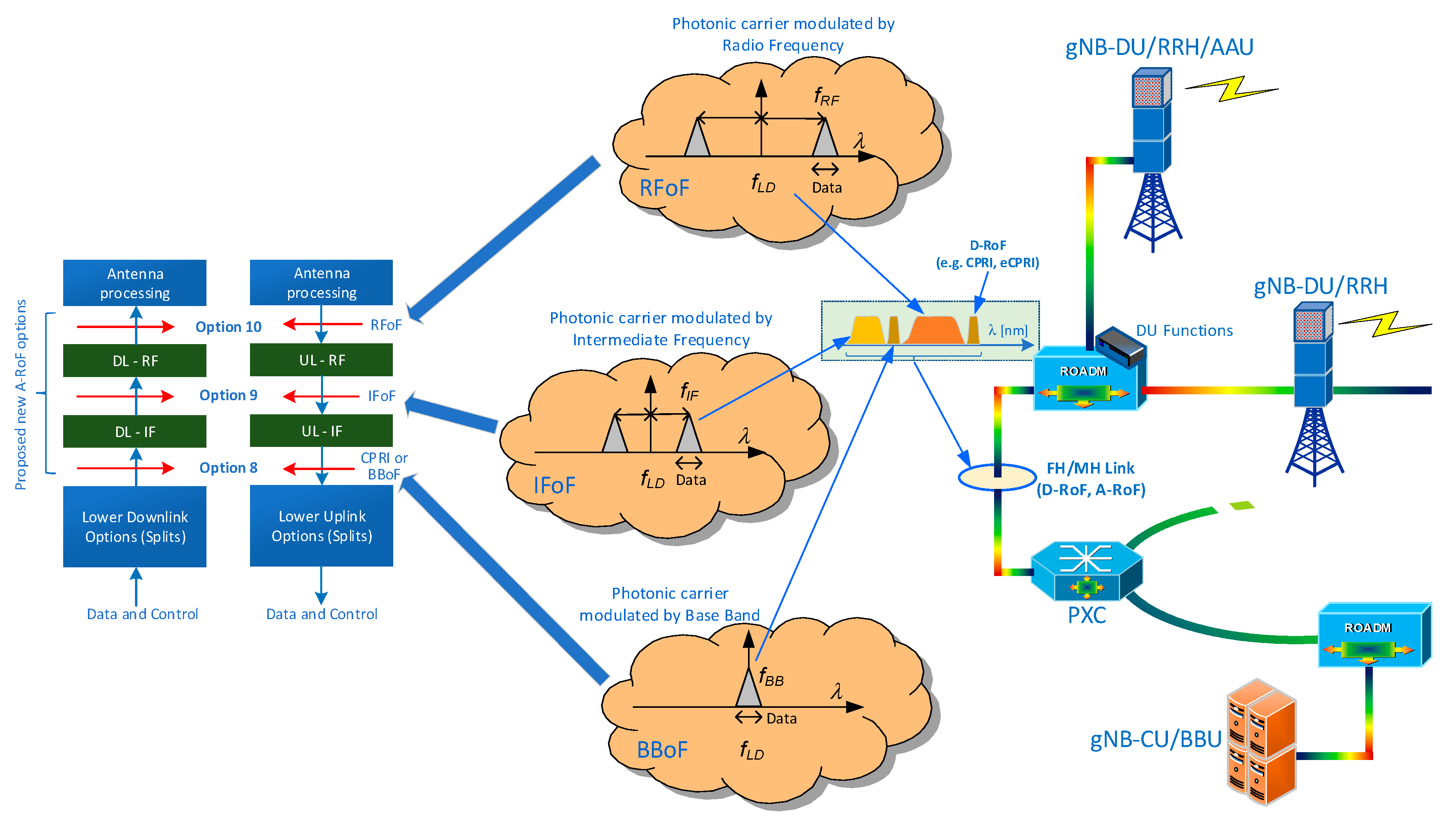
Digital fronthaul/midhaul interfaces are very demanding in terms of throughput, which is why in this part of the work we will consider the implementation of A-RoF solutions. In the analog mode of the photonic carrier modulation, we can use a modulating signal located in the baseband, the intermediate band, or the radio frequency band [
49]—
Figure 8.
In the case of photonic carrier modulation with a radio signal coming from the baseband, we have the largest saving of the photonic band. This technique requires the use of separate optical resources for each frequency BB channel. This causes complications in the need to use a separate optical channel or a separate optical fiber for each BB channel. As in the D-RoF interface, a modulator must be used on the gNB-DU/RRH side to allow the BB signal to be applied to the RF band. The second solution indicates the use of an IF intermediate frequency. In this technique, all frequency channels can be sent simultaneously to the selected RRH. In a remotely managed radio module, we convert the signal that transfers data from the intermediate band to the target RF band. This solution is quite economical, due to the possibility of optical transmission of many radio channels focused around one unified, in a given network, intermediate frequency, which can be selected depending on the needs. The solution that most occupies the optical band remains, that is, simultaneous transmission of all components of the radio signal, including the RF carrier. This solution is the least effective from the point of view of the FH network, but allows the use of maximally simplified AAU, whose tasks are reduced to optical modulation and demodulation, amplification, pre-amplification, and shaping the beam emitted by the antenna array.
In comparison to the D-RoF solutions, the signals in the A-RoF format do not occupy too much bandwidth in the optical channel, however, they are characterized by much higher requirements for distortions of modulating signals. The modulation signal is specific, because it resembles an analog format in spite of the fact that it transfers digital data. For many years, scientists have been working on the optical OFDM (O-OFDM) technique, which is very similar to the A-RoF such as baseband-over-fiber (BBoF) solution, but the On/Off Keying (OOK) method with a direct detection is still popular and the cheapest one. The modulation of the photonic carrier with a signal from the BB is therefore similar to the O-OFDM, however, there is only one source of carrier surrounded by two bands (double-side band (DSB) mode), thus the orthogonality of subcarriers remains on the side of the modulating signal. Care for the orthogonality of radio subcarriers, during transport in the optical path, is not a problem due to their very low frequency distance and the occurrence of multi-path effects in a small range (chromatic dispersion and power penalty influence—DSB mode), which occur on a much larger scale on the side of the wireless interface. Thus, the only limitations here are signal attenuation, its delay and dispersion, which must be taken into account in particular when using a very broadband modulation signal.
The use of high radio frequency allows the creation of more wider frequency channels (e.g., the need to use mmWave ranges in 5G); however, when using DSB modulation this results in a doubled increase in the width of the optical channel. This can be limited by using the SSB modulation technique by introducing Mach–Zehnder Modulation (MZM) in the Hilbert configuration or by filtering out one sideband. Such a treatment, however, weakens the modulating signal, at the expense of improving the bandwidth efficiency and reducing the impact of the chromatic dispersion of the fiber-optic paths. The large number of systems (2G–5G) supported by the base station causes its high degree of complexity and hinders its quick reconfiguration. In this case, there is a need to move all system functions to the CU cloud, where radio resource allocation will take place to individual antenna matrices mounted on the mast. The question arises, whether it is possible to coordinate all spatial streams using only one optical channel? Of course, this is not physically feasible, therefore there is a need to use the optical wavelength division multiplexing (WDM) technique or space division multiplexing (SDM) on the optical side (a larger number of optical fibers in the cable, or the use of multi-core optical fibers [
50]).
Optical resources are presented in the wavelength domain, because the optical fiber influences the change of the wavelength as a function of the optical frequency of the carrier. In order to evaluate the frequency bandwidth of the modulating signal, a basic relationship can be used
where
—radio frequency (RF) carrier (identifying the RF channel number),
—the extreme right frequency of the CP-OFDM sub-carrier of the baseband channel. The transition to the wavelength domain can be accomplished using the following approximate dependence
where
—the frequency of the optical carrier emitted by the laser radiation source. By substituting relation (4) into (5), we get
On this basis, it can be seen that the width of the optical channel is primarily dependent on the component that constitutes the radio frequency (RF). Regarding the relation (1), it can be seen that the efficiency of the analog solution is higher if the radio frequency used is higher, too. The simple design of the RRH/AAU connected via the A-RoF interface to the fronthaul/midhaul, enforces the use of optical multiplexing techniques, which will ensure full service of the MIMO radio technology. In case of the D-RoF interface, the use of CPRI/eCPRI enables the introduction of multiplexing of temporary TDM, which limits the need for multiple laser sources, but creates a very broadband optical channel. For 5G mobile systems, even at the level of a few-kilometer fiber-optic link, the D-RoF interface will need WDM/SDM multiplexing. Another issue is related to the multi-sectority of the RRH, which makes it necessary to use RF channel separating systems and direct them to the appropriate array of antennas in the sector. We can solve this by using a flexible grid of DWDM channels [
25], where the minimum frequency bandwidth of the optical channel is 12.5 GHz. The grid for the optical carrier is 6.25 GHz, but for the simplification resulting from the analog DSB modulation in the A-RoF interface, we assume that the carrier will change the frequency at least every 12.5 GHz. On this basis, the total occupancy of the optical band in the wavelength domain, using the formulas (4) and (5), can be written as the optical wavelength spectrum (OWS) [
23]
where
S—a number of sectors per RRH,
A—antenna modules array per sector;
—radio frequency bandwidth of
i,
j-th modulating signals;
—minimal frequency bandwidth of optical channel, which according to the DWDM grid is 12,5 GHz [
25] or smaller in the future EONs;
—the reference frequency for the optical carrier equal to 193,1 THz—according to [
25] or other band carrier;
c—a speed of light in free space equal to 3 · 10
8 mps.
The Formula (7) shown above allows the frequency bands to be combined with the count-down (sign “+”) or count-up (sign “−”) of the optical channel number relative to the reference frequency .
4. Calculation Results and Partial Discussion
In order to perform exemplary calculations indicating the bandwidth of fronthaul/midhaul links, using the previously presented interfaces, the initial parameters of radio signals that will occur in the 5G-NR Rel-15 wireless interface and subsequent releases should be set first.
In 5G mobile systems, a 4096-point FFT and a minimum 15 kHz spacing between the CP-OFDM subcarriers was introduced [
51]. Thanks to such arrangements, 5G-NR Rel-15 can cooperate with 4G (LTE Rel-8 and newer). The subcarrier spacing can be increased in a coherent proportion [
51], allowing the creation of broader combined frequency baseband channels—
Table 1.
The 3GPP Rel-15 of mobile systems has defined a physical layer and higher layers, but there are no restrictions that would indicate the number of antenna modules per sector. The extensive arrays of antennas make it possible to create systems for mass communication of the base station with many UE devices. Thanks to the usage of a higher number of antenna modules, the more accurately spatial beams can be determined. However, this entails the need to create a large number of data transmission channels and control channels. The demand for bit-rate is strictly dependent on the type of fronthaul/midhaul interface (type of Split/Option) that is between the mast with radio modules and the device preparing the radio signal for emission. The study assumes that the number of antenna modules per sector in the near future (5G Rel-15/16) should not exceed 256—
Table 1.
If a well-known CPRI interface is used in the fronthaul/midhaul, then the required split speed (Option 8/Split E) can be calculated using (1). Here, each antenna module has its own dedicated stream with a digitized signal from the BB range. This gives the possibility of convenient scaling with spatial resources (MIMO and beamforming) but forces the use of an optical network with very high bandwidth links.
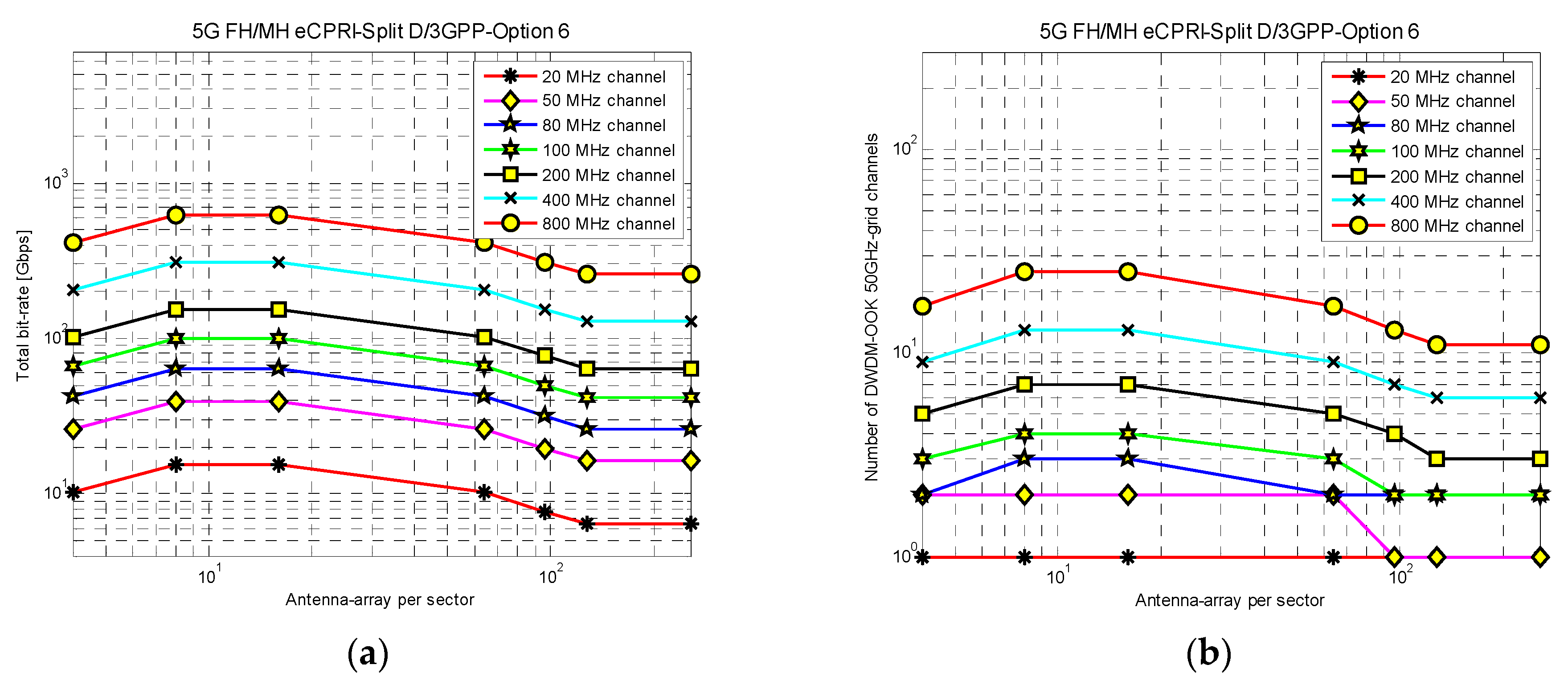
Figure 9a shows the results of calculations that visualize the total bit rate that will be generated by the heavily loaded, on the radio side, 4-sector gNB-DU/RRH, and
Figure 9b shows the number of optical DWDM-OOK-50GHz-grid channels (for CPRI stream/Option 10 [
31]—24.33 Gbps), which will have to be created in the FH/MH link to allow communication with the signal processing center. The calculations were made for 7 cases of BB channels (
Table 1), where only the last one is not compatible with the 5G-NR Rel-15.
Based on Formula (1) and
Figure 9, it can be seen that the increase in the bandwidth required for the CPRI link increases very strongly with the increase of the basic bandwidth (proportional increase in the sampling frequency). It should be noted that when the BB width increases, the number of CP-OFDM subcarriers is not significantly increased, therefore, when expanding the BB channel, the efficiency of using the CPRI interface becomes smaller and smaller.
It is possible to reduce the bandwidth demand when we lower the number of Split/Option level in the fronthaul/midhaul interface. This will, of course, entail an increase in the functions related to signal processing at the gNB-DU/RRH. In order to compare the degree of reduction in the bandwidth demand, calculations were made, the results of which in the form of diagrams are shown in
Figure 10 and
Figure 11.
At the discretion of the radio device communicating with the UE in the massive-MIMO mode, which will be connected to the gNB-CU cloud via the eCPRI-Split D/3GPP-Option 6, it cause to process the PHY signal in the UL and DL directions. This contact lies at the border between PHY and MAC layers, which is why it is clearly defined functional boundary (
Figure 7). The dependency (2) was used to calculate the bit rate generated at the level of this Split/Option and some assumptions were made, which are included in
Table 1 and
Table 2. The eCPRI interface is prepared for transporting of radio signals via Ethernet (RoE) paths, therefore the total redundancy of the frame headers go to 1.33 (
Table 2). At the Split D level, the number of active subcarriers in the specified BB channel is significant (in
Table 1 this is the first
NSC value, the second is the permissible number of subcarriers in NR-Rel-15, i.e., 3300). Therefore, the frequency bandwidth of the BB channel is not the reason for the bit rate increase in the Split/Option, but the number of active subcarriers and the number of layers created in order to be able to use MIMO and beamforming techniques at the level of radio-antenna modules. In this case, it was assumed that the number of layers is equal to the number of chains converting the signal into a digital form and vice versa (ADC/DAC)—the values were assumed approximately. The increase in the demand for spatial multiplexing in the wireless link will entail the need to increase these values. The larger bandwidth of the BB channel is applicable in higher millimeter RF bands (FR2) [
29], where the devices from the internet-of-things (IoT) group will be communicated, therefore the number of layers is much lower. The TDM technique parameters in the 5G-NR frames were kept the same as in LTE (4G), with the difference that when the frequency distance between CP-OFDM subcarriers increased, the duration of the symbols shortens proportionally, and their number in the time-frame increases. As a result, broader BB channels will be used in the massive machine-type communications (mMTC) and ultra-reliable and low-latency communications (URLLC), where OFDM symbols do not have to be too resistant to multipath effects occurring in the wireless channel. The results of the calculations presented in
Figure 10 show only the demand for the bandwidth of fronthaul/midhaul links at the level of the user plane (UP). The final bitrate must be increased by the control stream of the components on the gNB-DU/RRH board (control plane (CP)), but the increase in demand at the level of this Split/Option should not exceed 10% of the calculated value—
Figure 10.
Intermediate Splits/Options were introduced in all reference models (
Figure 7), however, they function differently. In this analysis, additional calculations were made for the eCPRI Split I
U/II
D (directions UL and DL), which is functionally similar to 5GPPP Split B (
Figure 7b,c). The results of calculations, carried out on the basis of (3), were placed in the form of diagrams in
Figure 11. It can be noticed that in this Split/Option the demand for fronthaul/midhaul the bandwidth is increasing slightly. This increase is mainly due to the fact that each mapped OFDM subcarrier must be quantized. The number of quantization bits per IQ subcarrier can be found in
Table 2. The increase of the speed of this Split/Option on the control plane (CP) will be significant, as it can reach even 30% of the UP flow.
Two new Option 9/10, as well as the extension of the functionality of Option 8 split were proposed in the paper—
Figure 8. To this end, a special design of an optical gNB-DU/RRH as a network node or network termination is proposed, which is equipped with appropriate radio components and photonics—
Figure 2,
Figure 3 and
Figure 4. Proposals are based on A-RoF solutions and are achievable if the fronthaul/midhaul links are based on an all-optical network using WDM technique. The calculations were carried out on the basis of a derived relation (7), and their results are presented in the form of diagrams shown in
Figure 12. In the Option/Split 10, the radio-frequency-over-fiber (RFoF) technique is used, which enables transporting radio signals through optical links exactly in the form in which they have be radiated in place of the radio-antenna device.
However, this solution has significant limitations, as with the increase of RF frequencies, photonic resources in fronthaul/midhaul links are very quickly occupied. This is due there being more and more optical channels from the DWDM standard grid—
Figure 12a. In the case of the RFoF, the use of photonic resources is effective when the radio carrier is located in the sub-6 (FR1) band—
Figure 12a—area marked with the number 1.
This technique fits very well in the simple and low energy analog beamforming (ABF) implementation on the AAU side, however, for each space beam (layer) a separate RFoF channel will have to be used. With Option 10, the DBF technique can only be implemented on the gNB-CU cloud side.
In the case of the need to use a higher radio carrier (>10 GHz), the RFoF method becomes ineffective. Here, it is worth using the intermediate frequency (intermediate-frequency-over-fiber (IFoF) technique) around 3 GHz (
Figure 12b)—we assume that the DWDM system scope will be exceeded due to the lack of the need for optical line amplifiers—short optical paths. The introduction of a much denser DWDM grid (evolution towards EON/UDWDM) will further increase the efficiency of optical path utilization. However, only if we use a lower intermediate frequency (IF) or use only basebands (BBoF technique) directed to individual antenna modules. In
Figure 12c, we see the cumulative OWS, but for zero RF carrier. In this case, the A-RoF mode was only used for BB signals, where a single BB signal occupies one optical channel with a width resulting from DSB modulation. The calculations were performed for the optical bandwidths of channels lying outside the standard DWDM grid [
25]—
Figure 12c. In a situation where one classic fiber is insufficient, it is recommended to introduce more fibers connected to one gNB-DU/RRH or use multi-core fiber in proportion to the number of sectors [
50].
It can be noticed that the analysis of the D-RoF and A-RoF interfaces is slightly different, because in the case of digitized solutions, the bit rate is the starting point, while in analog solutions we operate on the frequency band occupancy. Optical links based on the DWDM/UWDM network can be used to transport signals of different formats. It is only important that signals at the nodes of this network are correctly recognized due to the photonic band they occupy in the core of the optical fiber.
5. Applications of the Proposed Solutions
All the solutions proposed in the work above can be applied in developing mobile communication and wireless access systems. The main destination is the RAN domain, whose architecture evolves strongly towards C-RAN. The result is a search for solutions that will allow for an efficient transmission of processed radio signals to maximally simplified radio modules. The presented concept of the network (
Figure 5) is an unavoidable step that will allow virtualization of the computing power needed for the processed signals. The proposal for construction of the gNB-DU/RRH and coexistence of A-RoF and D-RoF links/paths in the same network is a combined approach to the solution that will enable dynamic management of optical resources of the fronthaul/midhaul, available cheap CU computing power, and radio resources.
Basic application scenarios for fronthaul/midhaul C-RAN networks (we assume that optical network (ON) and signal processing center (SPC) provide many other services to other recipients) are the following:
ON is heavily loaded, and SPC has a lot of free computing power resources. In this case, we can afford cheap signal processing even to the A-RoF. The A-RoF signals in most cases represent a high degree of spectral compression, so it will not be heavily loaded the ON links.
ON has a lot of free resources, and SPC is heavily loaded with other services. In this case, we can go to D-RoF modes, that is, lower the level of the split to the ceiling enabling the operation of the gNB-DU/RRH (even to Option 6 (eCPRI)—
Figure 7).
Both ON and SPC are not overloaded. A case in which the D-RoF with Option 8 (CPRI) support may be enabled—
Figure 7.
Both ON and SPC are heavily loaded. This is a very uncomfortable situation, because RAN has to go into the D-RAN mode, where the gNB-DU/RRH turns into the function of a classic gNB. A base station that does not have too much computing power and have limited access to the optical network must limit the supported wireless traffic.
Scenarios of detailed applications enabling switching the format in the fronthaul/midhaul link of the C-RAN (comparison with reference to the bandwidth in FH/MH links/paths of optical networks, without analyzing the demand for computing power during signal processing to the target form) are as follows:
The A-RoF and D-RoF interfaces on the same level of Option 8 (
Figure 7), i.e., CPRI and BBoF. The comparative calculations are shown in
Table 3.
The A-RoF and D-RoF interfaces located at different levels of split (
Figure 7), i.e., eCPRI and BBoF. Comparative calculations are shown in
Table 4.
The A-RoF and D-RoF interfaces located at different levels of split (
Figure 7), i.e., CPRI and RFoF. Comparative calculations are shown in
Table 5.
The A-RoF and D-RoF interfaces located at different levels of split (
Figure 7), i.e., eCPRI and RFoF. Comparative calculations are shown in
Table 6.
The A-RoF and D-RoF interfaces located at different levels of split (
Figure 7), i.e., CPRI and IFoF. Comparative calculations are shown in
Table 7.
The A-RoF and D-RoF interfaces located at different levels of split (
Figure 7), i.e., eCPRI and IFoF. Comparative calculations are shown in
Table 8.
For the calculations related to the conversion from the number of channels realizing communication in the optical fronthaul/midhaul link/path to the OWB, a simplified version of the Formula (7) was applied.
The proposed entirely optical network in this study may also have other applications. If the gNB-DU terminating devices are modified accordingly, then we can use them in other work areas. Light fidelity (Li-Fi) networks can be such an example. If the optical stream from the photonic switch (
Figure 3a) is guided directly to the light emitter, then it will be possible to implement the Li-Fi network. Before radiating, however, the signal should be properly amplified and scattered, because in the optical path of the xWDM-based network we cannot use too much optical power. An additional limitation is that the operating ranges of radiators that are in general use are not adapted to the optical bands used in fiber optic communication. If the Li-Fi network needs to be moved to the visible light communication (VLC) systems, basically all photonic elements of the proposed network will be subject to changes. Only the all-optical network architecture will remain unchanged. In the case of small-scale VLC networks, it is possible to use polymer optical fibers (POFs) and PXC/ROADM/OM/OD operating in the visible light range [
52].
6. Conclusions and Final Discussion
The proposed construction of the optical gNB-DU/RRH as O-RRH in [
23] should meet the set requirements, which mainly consist in handling optical signals occurring in the D-RoF and A-RoF formats. It is unlikely that such devices could be installed as part of the first release of 5G mobile systems, i.e., Rel-15/16, but in the future mass production of technologically advanced devices will certainly significantly reduce their unit price. The proposed radio-photonic device can be connected to the optical network as a node or termination of the path, which means that it is simply a radio access node whose operation can be implemented in the majority of software (SDN/SDR). Available transmission optical network resources and the available signal and data processing power of the gNB-CU/BBU cloud will be a decisive factor in the introduction of the type of Split/Option at a given moment.
The results of calculations presented in this paper show what capacity will be needed in fronthaul/midhaul networks, so that communication with such extended radio terminations will be effective. The first versions of the CPRI interface were not characterized by excessive bit rate, but they were to apply to 3G (UMTS) and 2G (GSM) mobile systems. Subsequent versions had to be adapted to 4G (LTE), where MIMO techniques and spatial beamforming were used more and more. Massive-MIMO technology, which is to be widely introduced in 5G, in order to start IoT communication, forces the use of very fast optical networks already in the local domain and access. This is caused by the need for surrounding the UE devices by antenna arrays that must be connected using very fast, synchronous, and flexible fronthaul/midhaul networks. Therefore, the CPRI splits will only apply where new techniques do not have too high requirements.
Figure 9a shows that with a number of more than 100 antenna modules, a 4-sector device supporting 400 MHz BB channels will need about 10 Tbps, which is equivalent to about 400 optical OOK-DSB-50GHz-grid channels—
Figure 9b. Of course, we can use coherent interfaces with high-order modulation and polarization multiplexing, which will reduce the demand for frequency bandwidth in the optical link several times, but the numbers will still be very large. Therefore, it is very important to introduce new solutions, among which one should reduce the throughput by introducing new Splits/Options.
Figure 10 and
Figure 11 show the calculation results for two selected eCPRI interface splits, where we see a very large drop in the demand for bit-rate. This is done at the expense of the need to perform more operations in the antenna-radio terminal, but the profit is significant, because the demand for bit-rate at the maximum values of the radio signal balances around 1 Tbps. This is associated with the occupancy of an acceptable number of optical DWDM/UDWDM channels in the fronthaul/midhaul optical path.
In order to increase the transparency of the potential application of the presented solutions, some exemplary scenarios (
Section 5) are given in which the transition from the D-RoF format to the A-RoF format is suggested. The basic scenarios constitute the merits of undertaking the research topic, as they show the direction of the RAN network evolution along with the increase in the use of fronthaul/midhaul links for this purpose, as well as the signal processing centers. Detailed scenarios are examples in which a specific D-RoF interface can be replaced with the A-RoF interface due to a smaller occupancy of the optical band in the fronthaul/midhaul link/path.
Scenario No. 1 concerns the comparison of BBoF and CPRI interfaces that work at the same split level—
Table 3. When using the BBoF optical channel with the minimum width matched to the modulation signal band, the gain is almost 24-fold.
Scenario No. 2 shows a comparative overview of BBoF interfaces (Option 8) and eCPRI (Option 6)—
Table 4. The eCPRI interface uses the fact that the so-called layers are most often associated with the number of radiated beams by use of DBF or HBF method. A large part of operations related to processing a radio signal is transferred to the gNB-DU/RRH. In this case, the gain for the optical UDWDM channel (1.5625 GHz) is over 19, while for the DWDM channel (12.5 GHz) only 2.4. In this example, it is clearly visible what effect the channel width has on the optical bandwidth saving, which is a serious technological limitation in the production of tunable lasers, photonics switches, and filters used in PXC/ROADM.
Scenario No. 3 concerns the comparison of RFoF (Option 10) and CPRI (Option 8) interfaces—
Table 5. In this comparison it is difficult to find a profit which for example BB 100 and 400 MHz channels shows losses. It should be added, however, that the RRH/AAU in the case of RFoF is almost completely unloaded from the signal processing. Here, even the RF carrier is built on the SPC/CU side. The calculations were carried out assuming a separate transfer of the BB channel with the RF carrier. If we send more BB channels on one RF carrier, then the profit will be significant, but we will limit the possibilities of independent beamforming in particular BB ranges. We eliminate this problem in the next scenario.
Scenario No. 4 includes the technique of creating layers that manage beams. Here we compare the RFoF (Option 10) and eCPRI (Option 6) interfaces—
Table 6. The situation is similar, because there is no profit here or there is a loss. Therefore, the situation is similar to scenario 3, and the significant difference in the occupation of the optical band between the scenarios results mainly from the compression consisting in the BB encoding in the layer-related stream.
Scenario No. 5 concerns the comparison between IFoF (Option 9) and CPRI (Option 8)—
Table 7. The introduction of the IFoF format for the 100 MHz BB channel gives about 3.3-fold gain on the optical FH/MH band. At the 400 MHz BB channel, the profit is already 6 times. In the case of the introduction of the BB channel multiplexing technique around IF subcarriers, the gain can be improved [
53].
Scenario No. 6 shows the comparison of IFoF (Option 9) and eCPRI (Option 6) interfaces, also for 2 sample BB channel widths—
Table 8. For both cases, we have a similar gain of around 3. The amount of profit will depend heavily on the selection of the IF subcarrier in relation to the selected optical channel width from the grid of the next generation of EON/UDWDM networks.
In the scenario examples we did not use the D-RoF digital indirect interface type eCPRI Split I
U/II
D—
Figure 7. In this interface there is a strict dependence of the final FH/MH link bandwidth on the BB channel width and the number of active CP-OFDM sub-carriers—
Figure 11. In the eCPRI Split D (Option 6) interface, the fronthaul/midhaul link rate depends only on the number of active CP-OFDM sub-carriers. Considering that in the 5G-NR wireless interface the frequency distance between the CP-OFDM subcarriers increases faster than the number of subcarriers themselves, therefore with the increasing BB channel width the eCPRI Split I
U/II
D interface will become increasingly less efficient with A-RoF (profit results will be between scenarios 1–2, 3–4, and 5–6 respectively).
Some of the issues related to the influence of the optical path or fiber-optic link on the behavior of the wireless radio channel has already been addressed in sub-
Section 3.2. However, to a large extent these issues are not covered by the topic of this paper. It can be assumed that an all-optical path/link guarantees the stability of the delay. The amount of delay depends on the optical path length or link. This parameter, however, seriously affects the work of the DBF or HBF (regardless of the method used [
54]), which requires conducting many calculations and practical tests in any implementation of subsequent C-RAN solutions. This applies to both the D-RoF format and the A-RoF format. With the narrowing the spatial beam on the side of the wireless link (massive MIMO), a faster feedback in the DBF control channel with the update of channel state information (CSI) data is needed—especially in the fast-moving UE. The use of HBF is helpful here, since the instant compensation resulting from the delay of the wired RAN part can be implemented with the ABF support.
Interferences that can occur between adjacent cells or sectors can be reduced by allocating other physical resource blocks (PRBs) (time-frequency isolation). In the case of sectors belonging to the same gNB-DU/RRH or gNB-CU and spaced apart, interference is even indicated due to the constructive spatial surrounding of the UE. Time-space synchronization in the area of the distributed base station ensures the implementation of joint transmission (JT) and high spatial gain. By means of an antenna-array consisting of a large number of modules, a very narrow beam can be radiated, thanks to which the channel will be resistant to multi-path. In the optical path or fiber-optic link, the previously mentioned phenomenon of chromatic dispersion has a static character. During the DSB transmission, a relative delay of the side bands occurs, in which there is a signal coming from the wireless channel. CP-OFDM symbols are protected against this phenomenon by inserting a guard interval with a cyclic prefix. The optical path enhances the multi-path phenomenon, but it is a constant parameter that can be quickly determined and compensated by the exchange of CSI. The compensation of optical fiber chromatic dispersion can also be implemented permanently at the end of the optical path/link, which will ensure a constant minimization of the impact on the transported radio channel signal in the target format.
The radio signal transported in the optical path in analog format is also influenced by noise. The main source of noise are the radio-photonic converters. The noise factor (NF) of the converter therefore decides on the extent of reduction of the SNR and indirectly influences the BER in the user channel. Optical power density should also be controlled due to the potential effect of nonlinear distortions. This is a price that in many cases is worth paying for a significant profit resulting from the compression of the used optical spectrum in the optical path/link. Studies of A-RoF interfaces in this area have been conducted for many years, and their results can be found in many papers and books [
34,
35].
The proposals for analog Splits/Options with high ID numbers (Option 8/9/10) may be useful in many solutions, but they cannot be universal, as in the case of CPRI. With the currently used grid of optical DWDM channels, the IFoF technique seems to be the most universal, since the intermediate frequency can be selected systematically, depending on the demand and available photonic resources. In this case, it is also possible to use a multistage BB signal transfer to the intermediate band. According to the calculations, the results of which are shown in
Figure 12 and
Table 3 and
Table 4, the use of the BBoF technique will become particularly important when a much denser UDWDM grid is available.
The possibility of introducing the O-OFDM format to optical links has been working for many years, and the results of research are more and more promising. This type of format does not differ significantly from the BBoF technique, because we have been hosting the OFDM format for over 25 years in wireless interfaces.
In order to indicate the degree of use of the optical channel by interfaces from the D-RoF family and others, used in classic NG-RAN solutions, the author carried out calculations, the results of which are presented in [
55]. The bit rates that will occur in the 5G network will undoubtedly be high. When approaching the next generation of mobile systems, i.e., 6G, we need to look for new solutions for optical networks. The issue of future capacity crunch of optical networks has been raised for several years [
56,
57,
58]. However, previous analyses concerned solutions for broadband backbone networks. The emergence of heavy IT traffic in the access domain is another new challenge. A serious generator of this traffic in the RAN domain is the widespread use of transporting digitized radio signals to an antenna MIMO modules. The introduction of radio signal transport in its original form will be a must. The flexibility of future all-optical EON networks will enable the introduction of another degree of freedom in optical resources management. As indicated above, depending on the type of Option engaged at a given moment, the occupation of the optical channel will vary within wide limits. In addition to WDM multiplexing, TDM technique can be introduced in digital channels. This will provide us with OTN or its newer generations with EON interfaces, in which optical OFDM may be used [
55]. In the case of A-RoF signals we can only use WDM technique. The flexibility of the optical network consisting in the optimal selection of the optical channel width for the A-RoF signal, as well as packing the channels independently of the DWDM grid, significantly increases the use of resources lying in the scope of optical nodes and the range of optical fiber single-modality. The latter is particularly important in network solutions with FTTA or PON architectures. An additional advantage of the optical link with the irregular grid of optical channels (EON feature) is a significant increase in resistance to non-linear distortions resulting from the Kerr effect. Interleaving of A-RoF and D-RoF optical channels will increase this resistance. With a large number of optical channels, the total power can reach a high density in the fiber core, but in fronthaul there is no need for high optical power. It is anticipated that on 5G fronthaul connections (high number Options) the transport of signals will take place over a distance of not more than 20 km. Therefore, problems in access networks will differ from those we see in wide area networks.
Another way to avoid capacity crunch of the fiber-optic networks in the NG-RAN access domain is to introduce new fiber technologies, i.e., multicore fibers (MCFs). The author proposed this type of solution for the first time in [
50]. Connecting O-RRH/gNB-DU to fiber optic cables based on multi-core structures will enable the implementation of the next SDM stage. If we combine the above dynamic interface selection solutions with new fiber-optic cable standards, there will be no problem with network congestion in the future. The next challenges to overcome are the construction of all-optical node devices that will be able to effectively switch the movement on the optical layer with flexible changing the optical channel grid. Switching will have to take place not only in the optical channel range, but also optical frames. For A-RoF signals from the NG-RAN domain, the 5G-NR interface frame synchronization with the optical layer switching system will be required.


