Review

The Gyrotrons as Promising Radiation Sources for THz Sensing and Imaging

1
Research Center for Development of Far-Infrared Region, University of Fukui, Fukui 910-8507, Japan
2
Gyro Tech Co., Ltd., Fukui 910-8507, Japan
3
Institute of Electronics of the Bulgarian Academy of Science, 1784 Sofia, Bulgaria
4
Institute of Applied Physics, Russian Academy of Sciences, 603950 N. Novgorod, Russia
*
Author to whom correspondence should be addressed.
Appl. Sci. 2020, 10(3), 980; https://doi.org/10.3390/app10030980
Submission received: 14 January 2020 / Revised: 23 January 2020 / Accepted: 28 January 2020 / Published: 3 February 2020
(This article belongs to the Special Issue Terahertz Sensing and Imaging)

Abstract

:
The gyrotrons are powerful sources of coherent radiation that can operate in both pulsed and CW (continuous wave) regimes. Their recent advancement toward higher frequencies reached the terahertz (THz) region and opened the road to many new applications in the broad fields of high-power terahertz science and technologies. Among them are advanced spectroscopic techniques, most notably NMR-DNP (nuclear magnetic resonance with signal enhancement through dynamic nuclear polarization, ESR (electron spin resonance) spectroscopy, precise spectroscopy for measuring the HFS (hyperfine splitting) of positronium, etc. Other prominent applications include materials processing (e.g., thermal treatment as well as the sintering of advanced ceramics), remote detection of concealed radioactive materials, radars, and biological and medical research, just to name a few. Among prospective and emerging applications that utilize the gyrotrons as radiation sources are imaging and sensing for inspection and control in various technological processes (for example, food production, security, etc). In this paper, we overview the current status of the research in this field and show that the gyrotrons are promising radiation sources for THz sensing and imaging based on both the existent and anticipated novel techniques and methods.

1. Introduction

The recent years are witnessing remarkable progress and the proliferation of various applications that are utilizing electromagnetic radiation with terahertz frequencies belonging to the so-called terahertz (THz) gap, which nowadays is more frequently referred to as the last frontier of the electromagnetic spectrum. This is stipulated by the unique properties of the THz waves, which are also known as THz rays (for an insightful comment on the legitimacy and the subtle distinctions of the usages of these two terms, see [1]). Among them, the following characteristics are the most notable. First, the terahertz radiation is invisible by a naked human eye, but it penetrates dielectric materials (e.g., plastics, paper, textile, wood) that are opaque in the visible range of the spectrum. At the same time, it is strongly absorbed by water and other polar liquids (solvents) but compared with visible and IR light is less affected by attenuation due to both Mie and Rayleigh scattering because of the significantly longer wavelength. Moreover, the terahertz waves are non-ionizing (in contrast to extreme-UV light and X-rays), non-invasive, non-destructive, and therefore biologically safe and harmless at low specific absorption rates. An even more important feature of the THz waves stems from the fact that their frequencies correspond to the characteristic frequencies (resonances) of the molecular motions (rotations, vibrations, stretching, hybrid modes of motion), and the irradiation of various gases and organic substances produces specific signatures that can be observed analyzing the resulting transmission, absorption, and reflection spectra. This allows using the THz waves for detecting/sensing many substances that exhibit such characteristic spectra. The basic mechanisms of such interactions are now well understood [2,3,4], and their underlying theoretical interpretations serve as a basis for the development of a wide range of methods and techniques [2,5] in material spectroscopy [6], bio-sensing [7,8,9,10], pharmaceutical industry [11], food inspection [12,13], and security [14].
The main components of any THz system that determine its operational performance are the used radiation sources [2,15] and detectors [16]. The terahertz region, a kind of “no man’s land”, which borders the microwaves and light and thus the domains occupied by the electronic and photonic devices, respectively, is nowadays being populated by various sources coming from both sides (“borders”) of this frequency range. It is believed that such convergence would finally lead to filling (bridging) the gap. The clear aims in such direction have been seen well in the recently formulated THz science and technology roadmap [17]. Despite the progress demonstrated by practically all radiation sources, there is a noticeable difference in their output power levels. Although sufficient for many applications, the power of the most frequently used solid-state devices (e.g., IMPATT and Gunn diodes, quantum cascade lasers (QCLs) that are tunable in a wide frequency range) is orders of magnitude lower than that provided by the vacuum tubes (initially mm-wave sources that recently advanced toward the THz frequencies) such as Backward Wave Oscillators (BWO), and accelerator-based electron-beam sources [18] (most notably the Free Electron Lasers (FEL) and storage rings). A conventional figure of merit that characterizes the latter devices, as well as the high-power microwave tubes, is given by the product of the average output power P and the frequency f squared ( P f 2 ). With respect to this value, the gyrotrons are among the most powerful sources of both pulsed and CW (continuous wave) coherent radiation in the terahertz frequency range and recently are contributing significantly to bridging the THz gap, providing terahertz waves for different applications in the fundamental scientific research and the technologies [19,20]. Some of them are well established (for example, the ECRH (electron cyclotron resonance heating) of fusion plasma, materials treatment, radars), while others have been born recently or are currently emerging. The latter include various advanced spectroscopic techniques such as for instance electron spin resonance (ESR), nuclear magnetic resonance with signal enhancement through dynamic nuclear polarization, (NMR-DNP), plasma physics studies, and novel medical technologies. The current state-of-the-art of the development and application of gyrotrons is well represented in the annually updated report [21] as well as in numerous recent review papers (see for example [22,23,24,25,26]). Here, our overview is focused on the potential of the gyrotrons as appropriate and versatile radiation sources for imaging and sensing.
The paper is organized as follows. The next section is a brief introduction to the physical principles of the operation of gyrotrons and discusses the main advantages of the radiation they produce. Some examples of successful usage of the gyrotrons for sensing, imaging, and spectroscopy are given in Section 3. The review ends up with conclusions and an outlook on the anticipated future prospects of the research in the field.

2. Advantages of the Gyrotrons as Powerful Radiation Sources for Sensing and Imaging

The gyrotrons are vacuum electron tubes that belong to the family of gyro-devices, of which other prominent members are the Gyro-Klystrons, Gyro-TWT (Traveling-Wave Tubes), Gyro-BWO (Backward-Wave Oscillators), and CARM (Cyclotron Autoresonance Masers). All of these utilize hollow electron beams in which the electrons follow helical orbits gyrating with a cyclotron frequency Ω c in a strong magnetic field B
Ω c = e γ m 0 B ,
where e and m 0 are the charge and the rest mass of an electron, respectively, and γ = ( 1 β 2 ) 1 / 2 is the relativistic Lorentz factor ( β = v / c being the electrons’ velocity normalized to the speed of light in vacuum c ). The operation of the gyro-devices is based on a physical phenomenon known as electron cyclotron maser instability, which takes place due to the relativistic dependence of the cyclotron frequency on the energy of the gyrating electrons provided a proper synchronism between the electron beam and the electromagnetic wave excited in the resonant cavity (usually a part of a cylindrical waveguide) is established in accordance with the following relations
ω = n Ω c + v z k z ,
ω 2 = c 2 ( k 2 + k z 2 ) ,
where ω is the circular frequency of the electromagnetic wave, n is the harmonic number of the cyclotron resonance, v z is the axial component of the velocity of the electrons, and k and k z are the transverse and the axial wave-numbers of the cavity mode, respectively. Therefore, the resonance condition (synchronization) can be conveniently presented graphically as an operation point at the intersection of the beam line (2) and the dispersion curve (3) of the corresponding cavity mode as shown on the Brillouine diagram in Figure 1.
During the beam–wave interaction, some electrons lose energy while others gain. Accordingly, the electrons for which the relativistic factor γ has been decreased will gyrate at higher cyclotron frequency while the accelerated electrons (with an increased γ) will rotate at decreased frequency. As a result of this relativistic effect, azimuthal bunching of the beam electrons occurs. Moreover, when the above conditions are satisfied, the formed bunch slips toward the decelerating phase of the electromagnetic wave, where it can transfer its energy via bremsstrahlung. In the case of gyrotrons, the Doppler shift term v z k z is small, and practically, they operate at frequencies close to the cyclotron frequency or its harmonics, which means roughly 28 GHz per Tesla at the fundamental resonance ( n = 1 ). Therefore, there are two routes for raising the frequency of the generated radiation: namely increasing of either the magnetic field intensity (which is limited only by the available superconducting magnets) or the harmonic number of the cyclotron resonance. Although the latter approach is hindered by severe mode competition and significantly lower efficiency, there is remarkable progress in the development of gyrotrons operating at high harmonics. They include second-harmonic conventional gyrotrons (utilizing helical electron beams with off-axis orbits) [27,28,29,30,31,32] as well as tubes based on advanced concepts such as LOG (large-orbit gyrotrons with axis-encircling aka uniaxial electron beams) [33,34,35] and double-beam gyrotron [36]. The highest frequencies achieved by the gyrotrons have already passed the symbolic threshold value of 1 THz. For example, the pulsed gyrotron developed at the Institute of Applied Physics (N. Novgorod, Russia) has demonstrated an operation at 1.3 THz (with output power of 1 kW in pulses of 20 μs and energy of 30 mJ) exciting the TE24,4 mode (fundamental operation) at magnetic field intensity of 51.5 T [37]. Approximately at the same time, the gyrotron FU CW III with a 20 T superconducting magnet that was developed at FIR-UF (Fukui, Japan) has achieved a continuous wave (CW) second-harmonic operation on the mode TE4,12 at a frequency of 1.08 THz [38].
The gyrotrons are fast-wave devices since in their resonant structures (cavities), the phase velocity of the wave is greater than that of light in vacuum (i.e., it is superluminal) and they, unlike the classical microwave tubes, do not need tiny slow-wave structures with characteristic dimensions of the order of the wavelength of the generated radiation and positioned close to the electron beam. This allows the use of oversized resonators with radii significantly exceeding the wavelength and therefore powerful electron beams of high currents without losses or damage of the resonant structures, thus achieving higher output powers.
The structure of a gyrotron is shown schematically in Figure 2. It includes an electron-optical system (EOS) based on a diode or triode magnetron injection gun (MIG) with a thermionic cathode that generates a helical electron beam with appropriate parameters (accelerating voltage, current, injection radius, and thickness in the cavity) and high quality (low spreads δ v z , δ v of both the axial v z and the transverse v velocities of the electrons; azimuthal uniformity; absence of reflected (trapped) electrons and losses on the electrodes). Since in the gyrotrons, the energy is extracted only from the rotational (transverse) motion of the beam electrons, an important parameter that affects the efficiency of the interaction is the velocity ratio (aka pitch factor) α = v / v z . Starting from the emitter of the MIG, it is increased adiabatically in the beam tunnel by the rising magnetic field generated by a set of solenoids (notably the superconducting magnet) to typical values of α = 1.2 ÷ 1.5 in the resonant cavity.
A fine-tuning of the pitch factor is possible by varying the potentials of the electrodes of the MIG and the currents of the auxiliary gun coils. In the simplest case, the electrodynamical system, which is responsible for the mode selection and where the beam–wave interaction takes place, is a section of a circular waveguide delimited at both sides by appropriate down- and up-tapers that control the resonant properties of the cavity (e.g., the diffractive Q factor) and serve as transitions/connectors to the beam tunnel and the output waveguide, respectively. In the oversized cavities, a dense spectrum of modes presents the inevitable problem of mode competition, but this is being solved using different techniques (basically electronic and electrodynamic) for mode selection as well as by careful computer-aided design (CAD) and manufacturing of the resonator. While the radiation generated inside the cavity has a complicated polarization and spatial distribution corresponding to the field pattern of the operating mode, many applications require a well-collimated linearly polarized beam. That is why most of the gyrotrons nowadays have a quasi-optical (QO) internal mode converter consisting of a launcher (of either Vlasov or Denisov type) and a system of mirrors that produces a Gaussian wave beam. The QO system serves also to separate the spent electron beam and the wave beam. The former is dissipated on the water-cooled collector, while the latter is transmitted through an output window. In the most advanced gyrotrons, depressed collectors are being used for recuperation (recovery) of part of the energy of the spent electron beam and increasing in such a way the overall efficiency.
Both the overall weight and the dimensions of the gyrotrons are determined by the biggest component: the superconducting magnet. Compared to the conventional microwave tubes and the solid-state devices they are bulkier, but at the same time, they are much more compact than the accelerator-based sources and FEL. Recently, the availability of cryogen-free superconducting magnets with smaller dimensions has made it possible to develop compact (portable and almost table-top) gyrotrons that can be easily embedded in the laboratory infrastructure used for spectroscopy, imaging, inspection, etc. Some of them will be mentioned in the following section.
The main advantages that characterize the gyrotrons as versatile radiation sources for various applications in THz science, spectroscopy, sensing, and imaging are listed in Table 1 and will be commented briefly below.
Many applications (e.g., radars, ESR and NMR-DNP spectroscopies, measurements of the hyperfine splitting (HFS) of positronium) impose high requirements on the spectral characteristic of the used radiation most notably on the linewidth, mode purity, and stability of the frequency. Although there are inevitable factors that contribute to the widening of the spectrum such as fluctuations of the accelerating voltage and electron-beam noises (flicker, shot, etc.), in a well-designed tube, their influence is minimized and the spectral characteristics are appropriate for the mentioned applications [39,40,41,42,43]. For example, the detailed measurements of the spectral characteristics of a 0.14 THz gyrotron for NMR-DNP have shown an FWHW (full width at a half maximum) linewidth of 7.2 kHz [40,41]. In an analogous study performed using a 0.263 THz gyrotron for spectroscopy, a spectral width Δf of about 0.5 MHz (Δf/f ∼ 10−6) has been reported [42]. In [43], long-term frequency stability better than 1 MHz has been demonstrated in a 0.26 THz DNP-NMR gyrotron. The radiation linewidth determined by the anode voltage fluctuations (δVa/Va = 0.3%) has been estimated to be as low as δf = 3 MHz. By an appropriate stabilization of the used cathode and anode high-voltage power supplies and applying a feedback control of the beam energy, relative widths of the frequency spectrum Δf/f and the frequency fluctuations δf/f lower than 1 × 10⁻⁹ and 3 × 10⁻¹⁰, respectively, have been achieved at FIR UF in the first experiment on the high-frequency stabilization of submillimeter-wave gyrotron [44]. In the subsequent studies, the technique of the output parameters stabilization based on PID control has been mastered, and now it is routinely used in the gyrotrons for DNP-NMR spectroscopy [45,46]. It allows stabilizing the output power and frequency separately [47] as well as simultaneously [48], although in the latter case, the levels of the stabilizations are lower. Nevertheless, however, such a trade-off provides sufficiently stable radiation for the mentioned spectroscopic experiments. Generally, what is nowadays typical for the DNP-NMR gyrotrons is a long-term frequency stabilization with 0.2–0.4 MHz frequency spectrum width (stabilization is better than 10−6) [47].
Recently, a breakthrough result has been demonstrated by a high-power sub-terahertz (0.263 THz/100 W) gyrotron with a record frequency stability within 1 Hz, which was realized using a phase-lock loop in the anode voltage control [49]. The relative width of the frequency spectrum and the frequency stability reported in [49] are 4 × 10⁻¹² and 10−10, respectively. These parameters are better (by almost three orders of magnitude) than those demonstrated so far by other high-power sources.
Besides these spectral characteristics, a very important function required by many applications is the frequency tunability. In the case of gyrotrons, it can be performed in three different ways [50]. The first one is step-wise, and the tunability is being achieved switching to different operating modes by varying the cyclotron frequency (see Equation (1)), changing the accelerating voltage (and thus γ) or the magnetic field. The second one is a smooth continuous tunability, which is based on the excitation of a sequence of high-order axial modes (HOAM) [51]. The third possibility (which is rarely used due to the additional technical complications that it introduces) involves changing the dimensions and the shape of the cavity mechanically or by temperature control of the expansion/contraction of the resonator [52]. Efficient multi-frequency gyrotrons that are step-tunable in wide frequency ranges have been demonstrated in numerous experiments [50,53,54,55,56,57,58,59,60]. An already classical but still impressive example of a stepwise tunability in a wide frequency band is the GYROTRON V developed at the University of Sydney [53]. Its operating frequency at the fundamental resonances has been tuned from 0.15 to 0.3 THz and extended by a second-harmonic operation to above 0.6 THz with output powers, respectively of up to 20 W and hundreds of mW in the frequency ranges 0.15–0.3 THz and 0.3–0.6 THz. The second method for frequency tuning via a successive smooth passage through a sequence of overlapping HOAM is very convenient for many spectroscopic techniques, and its successful realization has been reported in many studies [57,58,59,60]. For instance, a continuous tuning in a 6 GHz band (from 0.134 THz to 0.14 THz) has been achieved in the gyrotron FU CW IV (FIR-UF) operating on a sequence of TE1,2,q modes having axial indices q = ± 1 , 2 ,   3 , 4 (where the negative values correspond to the gyro-BWO operation) by varying the magnetic field from 4.9 to 5.2 T [58].
Both the frequency and amplitude modulations are essential for many applications, such as for example in the remote sensing of atmosphere, communications, advanced diagnostic and spectroscopic techniques, etc. Recently, it has been demonstrated that the signal enhancement in the DNP-NMR spectroscopy can be increased significantly by using frequency-modulated CW radiation [61,62,63]. In the gyrotrons, the mechanism of frequency modulation is based on the relativistic dependence of the cyclotron frequency on the energy of the electrons (as it has been explained by Equation (1)) and is being realized by alternating the body potential of the tube and therefore by varying the accelerating voltage [64]. Although the variation of the frequency Δ f f / 2 Q is limited by the quality factor Q of the resonator, a modulation depth sufficient for many practical purposes can be obtained. A good example of a radiation source with such capabilities is the 0.46 THz gyrotron FU CW GVI (developed at FIR UF and used in the 700-MHz DNP-NMR spectrometer at the Osaka University under the name Gyrotron FU CW GOI) [65]. It has the following modulation characteristics, which are appropriate for this particular measuring system but more generally illustrate this eminent feature and advantage of the gyrotrons. A modulation amplitude of up to ±50 MHz is obtained with the cavity potential variation of ±0.5 kV with a modulation frequency of 300 Hz. In these experiments, both sinusoidal and triangular modulations of the beam voltage have been used. At some modulating parameters (frequency and amplitude of the modulating signal), a linear dependence of the frequency variation on the voltage variation has been observed. Analogously, by sweeping the anode voltage in a frequency tunable 0.26 THz gyrotron and sweep rates up to14 kHz, a 60% gain in the signal enhancement has been observed [65].

3. Illustrative Applications of Gyrotrons to Advanced Spectroscopic Techniques, Imaging, and Inspection

3.1. Advanced Spectroscopic Techniques

3.1.1. DNP-NMR and ESR Spectroscopy

The spectroscopy based on nuclear magnetic resonance (NMR) is a powerful and widely used method for studying a big variety of compounds (e.g., complex biomolecules such as proteins) in biomolecular research, material, and pharmaceutical sciences. However, its main drawbacks are low sensitivity, low signal-to-noise ratio, and, respectively, long spectrum acquisition times. A technique developed at MIT [66] for enhancement of the NMR signal through a dynamic nuclear polarization has radically solved these problems. It involves adding a polarizing agent to the sample, irradiation by gyrotron radiation, and transferring the polarization of the unpaired electron spins to the neighboring nuclear spins. In other words, DNP-NMR is a combination of two techniques, namely electron paramagnetic resonance (EPR), aka electron spin resonance (ESR), and NMR, which provides a significant (theoretically, up to several orders of magnitude) increase of the sensitivity and decrease of the acquisition time. After the pioneering breakthrough [66], a series of gyrotrons for DNP-NMR spectroscopy have been developed at MIT [24], where the first 140 GHz system has been followed by a series of spectrometers utilizing gyrotrons with output frequencies of 250, 330, and 460 GHz and operating at the second harmonics of the corresponding cyclotron resonances. For coupling of the gyrotron radiation to the sample, low loss transmission lines are being used. For application in the time-domain DNP-NMR techniques, two gyro-amplifiers operating at 140 GHz and 250 GHz, respectively, have been developed as well.
At FIR UF, a series of CW gyrotrons (the so-called FU CW series) has been developed [23,26,67,68]. They occupy a wide area in the parameters space of the output power and frequency and are being used in various studies ranging from materials processing and characterization to novel medical technologies. However, the biggest portion of this series consists of the radiation sources dedicated to advanced spectroscopic techniques. Photos of some of them are shown in Fig. 3. One of them, the gyrotron FU CW II, is built using an 8 T liquid-He-free superconducting magnet (SCM) and generates radiation with a frequency of 394.6 GHz (operating at the second harmonic of the cyclotron frequency) that corresponds to the 600 MHz proton NMR at a magnetic field intensity of about 14 T. An optimized version of this tube (FU CW IIB) is characterized by a high stability of the output power (fluctuations lower than 0.5% during 18 h CW operation) achieved by using PID feedback control. The next radiation source, FU CW IV, for 200 MHz DNP-NMR spectroscopy uses a 10 T cryogen-free SCM and has demonstrated continuous tunability in a broad frequency band from 134 to 140 GHz simply by changing the magnetic field in the cavity from 4.9 to 5.2 T and operating as a gyro-BWO on a sequence of high-order axial modes (HOAM). The same technique for smooth frequency tunability has been achieved by the gyrotron FU CW VI, which has a SCM with a maximum field intensity of 15 T. It has been designed as a radiation source for the 600 MHz DNP-NMR spectrometer of the Institute for Protein Research (IPR) at Osaka University. One of the most versatile tubes, namely FU CW VII, can be used for both 300 and 600 MHz DNP-NMR at output frequencies of 200 GHz (fundamental operation) and 400 GHz (second harmonic), respectively. This gyrotron is step-tunable in a wide range (from 86 to 223 GHz), since many operating modes can be excited in this frequency band by varying the electron beam parameters and the magnetic field.
Specific requirements imposed on the gyrotrons used as radiation sources for spectroscopic studies stem from the fact that they have to be embedded in sophisticated laboratory infrastructure, and thus, it is desirable to minimize their weight and dimensions. Additionally, the DNP-NMR spectroscopy demands a well-collimated (Gaussian) wave beam with a linear polarization, which has to be transmitted and coupled to the sample with low losses. In order to satisfy these requirements, two new clones of the FU CW series have been developed, namely FIR FU CW C and FIR FU G. In their notations, the symbols C and G stand for “compact” and “Gaussian beam”, respectively. For instance, the overall height of FU CW CI is 1.02 m, while that of CII is only 0.86 m. FU CW CI has been designed having several applications in mind, including 600 MHz DNP-NMR spectroscopy. It utilizes a compact He-free 8 T SCM, operates at a frequency of 395 GHz, and provides radiation with an output power of 120 W. The gyrotrons of the CW G series have internal (built-in) mode converters and deliver Gaussian-like beams with an almost circular cross-section. Some of them are designed and optimized especially as radiation sources for 600 MHz (FU CW GII at 395 GHz) and 700 MHz (FU CW GVI and GVIA at 460 GHz), respectively. At IPR, where these gyrotrons are installed, a slightly different nomenclature is used. According to it, FU CW VI and VIA are denoted as FU CW GO-1 and GO-II, where “GO” indicates that the tube delivers an optimized Gaussian output beam. The collage in Figure 3 shows photos of some of the gyrotrons belonging to the FU CW series and used for spectroscopic studies.
A second-harmonic gyrotron for DNP-NMR spectroscopy that provides radiation with a frequency of 0.26 THz and power of 100 W has been developed at IAP-RAS [25]. This radiation source has been embedded in an NMR spectrometer at the Institute of Biophysical Chemistry of Goethe University (Frankfurt-am-Main, Germany). The transmission line (13 m long), which delivers the radiation from the output window of the gyrotron to the spectrometer, includes an external mode converter that transforms the operating mode TE23 into the hybrid linearly polarized mode HE11; a corrugated waveguide section; four miter bends; a variable polarizer–attenuator; a water load combined with a calorimeter; and a two-position power switch. The experiments conducted at this spectrometer have demonstrated an increase of both the sensitivity and the resolution by more than 80 times. A successor of this tube is another gyrotron for DNP-NMR spectroscopy operating at the same frequency (0.26 THz) but at the fundamental resonance and therefore at higher levels of both the output power and efficiency [42]. It has demonstrated a maximum CW power up to 1 kW at high beam current (0.4 A) and an output power of about 10 W (which is sufficient for most of the spectroscopic applications) in a low-current (0.02 A) regime.
There is an empirical law according to which the strength of the magnets for NMR (measured by the frequency of the proton resonance) increases by 100 MHz every 5 years. It is anticipated that the next generation of the NMR spectrometers will reach 1.2 GHz, and Bruker has already announced that such a magnet (with a field intensity of 28 T) is already commercially available [69]. DNP-NMR spectroscopy at such magnetic fields requires a radiation source that provides a sufficient output power at a frequency of 0.8 THz. Motivated by this prospective, an international research team has developed the first second-harmonic double-beam gyrotron with appropriate characteristics for such an application [70]. This has been made possible due to the specific additional means for mode selection, which this concept offers in solving the problem of mode competition between fundamental and second-harmonic resonances. The experimental results of the investigations of this radiation source [71] are in agreement with the theoretical expectations and prove the potential of the double-beam tubes for further advancement to higher frequencies. A photo of this unique tube is shown in Figure 4.
Analogously to DNP-NMR, the sensitivity of the ESR spectroscopy increases significantly, advancing toward higher intensities of the magnetic field and correspondingly to higher frequencies. Another possibility for increasing the sensitivity and spectrum acquisition time is the usage of coherent pulses instead of CW radiation. In order to realize this advanced concept, novel instrumentation for pulsed ESR (also referred to as Fourier transform ESR) has been developed recently [72] at FIR UF. In the measuring system, the gyrotron FU VIIA is used as a radiation source and short millimeter-wave pulses with a controllable time delay are generated by a light controlled semiconductor shutter. The used experimental arrangement allows implementing the method of electron spin-echo envelope modulation (ESEEM) in the measurements. An important advantage of ESEEM is that it makes it possible to measure the relaxation times of the electron spins, which is important for the materials science studies on compounds with short relaxation times.

3.1.2. Measurement of the Hyperfine Splitting (HFS) of Positronium

The positronium is a metastable bound state of one electron and a positron that forms an exotic hydrogen-like atom. It can exist in two states, namely ortho-positronium (o-Ps) and para-positronium (p-Ps). The energy splitting between o-Ps and p-Ps, i.e., the HFS is about 203.4 GHz. A significant discrepancy of 3.9 standard deviations between the measured HFS values and the theoretical prediction of the quantum electrodynamics (QED) motivated the development of a novel method for the direct and precise evaluation of HFS [73]. In contrast to the previous indirect methods (e.g., measuring the Zeeman splitting in a static magnetic field) that are prone to systematic errors, the new approach relies on a stimulated transition between o-Ps and p-Ps states induced by irradiation with a strong electromagnetic wave with a frequency of about 203 GHz generated by a gyrotron. The experimental setup includes a transmission line that delivers and couples the wave beam to a high-finesse Fabry-Pérot (FP) cavity in which a power of about 10 kW is accumulated, and it includes a gas chamber and a positron source as well as a set of detectors and an electronic control system. The positronium is formed in the cavity using a 22Na source of positrons and nitrogen mixed by iso-butane as a stopping target. The schematics of this experimental arrangement are shown in Figure 5. Under the irradiation by a 203 GHz wave, some of the o-Ps (decaying into three photons) transit into p-Ps (decaying into two photons), and consequently, the ratio of two-photon events increases. This process is monitored by the photon detectors (LaBr3(Ce) scintillators) that are located around the cavity. In the measurements, the frequency of the gyrotron is varied within approximately 2 GHz in order to observe a Bret–Wigner resonance of the transition. The hyperfine transition has been observed with a significance of 5.4 standard deviations. The transition probability that has been measured directly for the first time is found to be A = 3.1 ± 1.2 1.6 × 10 8 s−1, which is in a good agreement with the theoretical value of 3.37 × 10⁻⁸ s−1 [74]. Recently, the whole Breit–Wigner resonance of the transition from o-Ps to p-Ps has been measured for the first time using a frequency-tunable millimeter-wave system and tuning the gyrotron in a very wide range from 201 to 205 GHz by changing successively several gyrotron cavities of different radii.

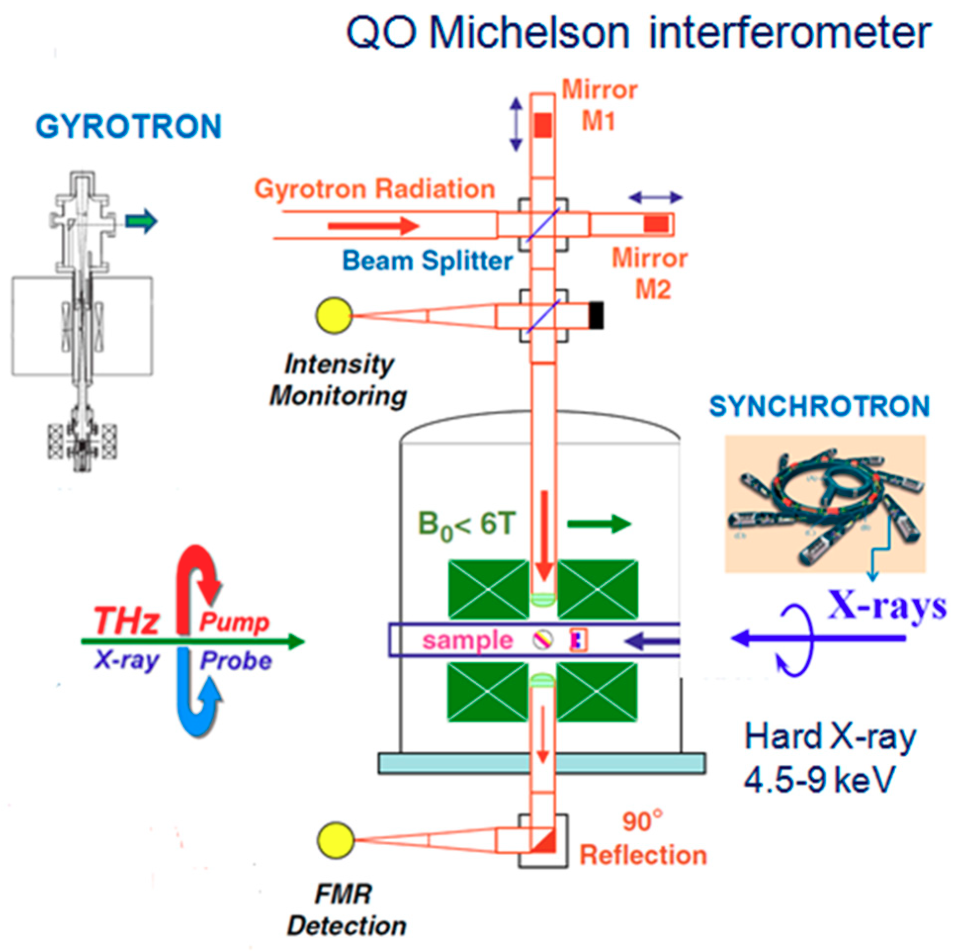
3.1.3. X-ray Detected Magnetic Resonance (XDMR) Spectroscopy

The XDMR spectroscopy is a new and unique element- and edge-selective technique [75] which allows to resolve and study the precession dynamics of spin and local orbital magnetization components. In this Pump&Probe technique (see Figure 6), the X-ray magnetic circular dichroism (XMCD) is used to probe the resonant precession of the magnetization produced by the irradiation with a strong microwave pump wave applied perpendicularly to the static magnetic field. The utilization of gyrotrons as powerful pump sources allows to extend this technique to the sub-THz frequency range and, respectively, to stronger magnetic fields. The first proof-of-principle feasibility study on the sub-THz XDMR spectroscopy has been conducted at the European Synchrotron Radiation Facility using a refurbished version of the gyrotron FU II which was operated at 76 and 138 GHz (fundamental resonances of the TE011 and TE021 modes, respectively). It is anticipated that this promising spectroscopic technique can be used for investigation of various electro-optical and magneto-electric effects, including the dynamics of Van Vleck orbital paramagnetism, as well as for studies on both optical and acoustic modes in ferrimagnetic and antiferromagnetic systems [76].

3.1.4. Radioacoustic Spectroscopy Using Gyrotron Radiation

Nowadays, the gas molecular spectroscopy (which is, in fact, one of the earliest applications in the terahertz spectral region) is a powerful tool used in various fundamental and applied studies as, for example, qualitative and quantitative gas analysis, non-invasive medical therapies, atmospheric remote sensing, and so on. As for any other spectroscopy, sensitivity is the main issue, since this key parameter determines the accuracy of the measurements and eventually the scope of the problems to which this technique can be applied. The current levels of the achieved sensitivity in the conventional schemes of mm-wave spectrometers have already approached the physical limits. The only known method for further increase of the sensitivity is based on the opto-acoustic (aka photo- or radioacoustic) detection of absorption. In this method, the result of the interaction of the radiation with matter is detected rather than the radiation itself. An efficient approach for increasing the sensitivity of the radioacoustic detection (RAD) by increasing the power of the radiation source has been realized in an automated facility [42]. The schematics of the spectrometer are shown in Figure 7. As a radiation source, it uses a gyrotron developed at IAP-RAS and operated in CW regime at a frequency of about 263 GHz (which can be tuned continuously within an interval of 0.2 GHz by varying the electron beam voltage and the temperature of the cavity) with an output power of up to 1 kW. The width of its radiation spectrum Δ f is about 0.5 MHz ( Δ f / f ~ 10 6 ) and is determined by the fluctuations of the accelerating potential instabilities of the accelerating potential provided by the high-voltage power supply. Recently, the capabilities of the RAD spectrometer have been demonstrated using as a test gas sulfur dioxide (SO2), which has a very dense and a well-studied spectrum in the mm/sub-mm range. It has been estimated that the maximum absorption sensitivity of the spectrometer is of the order of 6 × 10⁻¹⁰ cm−1. The bottom line of these experiments is that an increase in the scanning radiation power by about three orders of magnitude leads to a proportional increase in the sensitivity of the RAD spectrometer [77]. This result clearly proves the efficiency of the outlined “power” approach and suggests some direction for a further realization of its potential; however, this is limited by the spectral line saturation effect. The latter problem can be substantially reduced by proper selection of the molecule, the transition, and experimental conditions. It is believed that through combining this method with complementary conventional techniques (e.g., increasing the optical path), a record-breaking sensitivity can be achieved.
Recently, the operational performance of the gyrotron used in the RAD spectrometer has been improved significantly. Most notably, the radiation frequency has been stabilized against a reference oscillator using a phase-lock loop (PLL) system in the anode voltage control, which provides high stability, narrow bandwidth (relative width of approximately 10−12), and an accurate frequency control. Sample spectra have been registered at the first (263 GHz), second (526 GHz), and third (789 GHz) harmonic of the cyclotron frequency with the modulation of both the output power and frequency.

3.2. Remote Atmosphere Sensing Using Gyrotrons

The gyrotrons have demonstrated their potential as radiation sources for the remote sensing of clouds in the atmospheric window at 94 GHz (where the Rayleigh scattering from the droplets in the cloud have a cross-section that is proportional to λ 4 ) a long time ago [78]. Ground-based radiometry in this frequency range has been extremely useful in detecting upper-atmosphere trace elements [78]. Nowadays, the Gyro-TWA (Gyrotron Travelling Wave Amplifiers) are considered as even more appropriate, as they offer a 10-fold increase in the available bandwidth and a fivefold increase in the peak power over the amplifiers used in the current cloud profiling radars. It is expected that this will lead to a significant increase of the radar sensitivity, enabling the detection of smaller particulates, with higher resolution, at both longer ranges and shorter timescales. The technology also has the potential to be applied to the ground-based mapping of space debris, which is a major consideration for all orbiting systems, including environmental monitoring satellites [79]. A novel W-band Gyro-TWA for cloud radar applications developed at the University of Strathclyde is based on a helically corrugated resonant structure and utilizes an axis-encircling (aka uniaxial) electron beam formed in an electron-optical system with a cusp electron gun. This tube can provide a maximum power of 5 kW at its center frequency of approximately 94 GHz with an instantaneous frequency bandwidth of 10 GHz operating at a high pulse repetition frequency of 2 kHz [80].

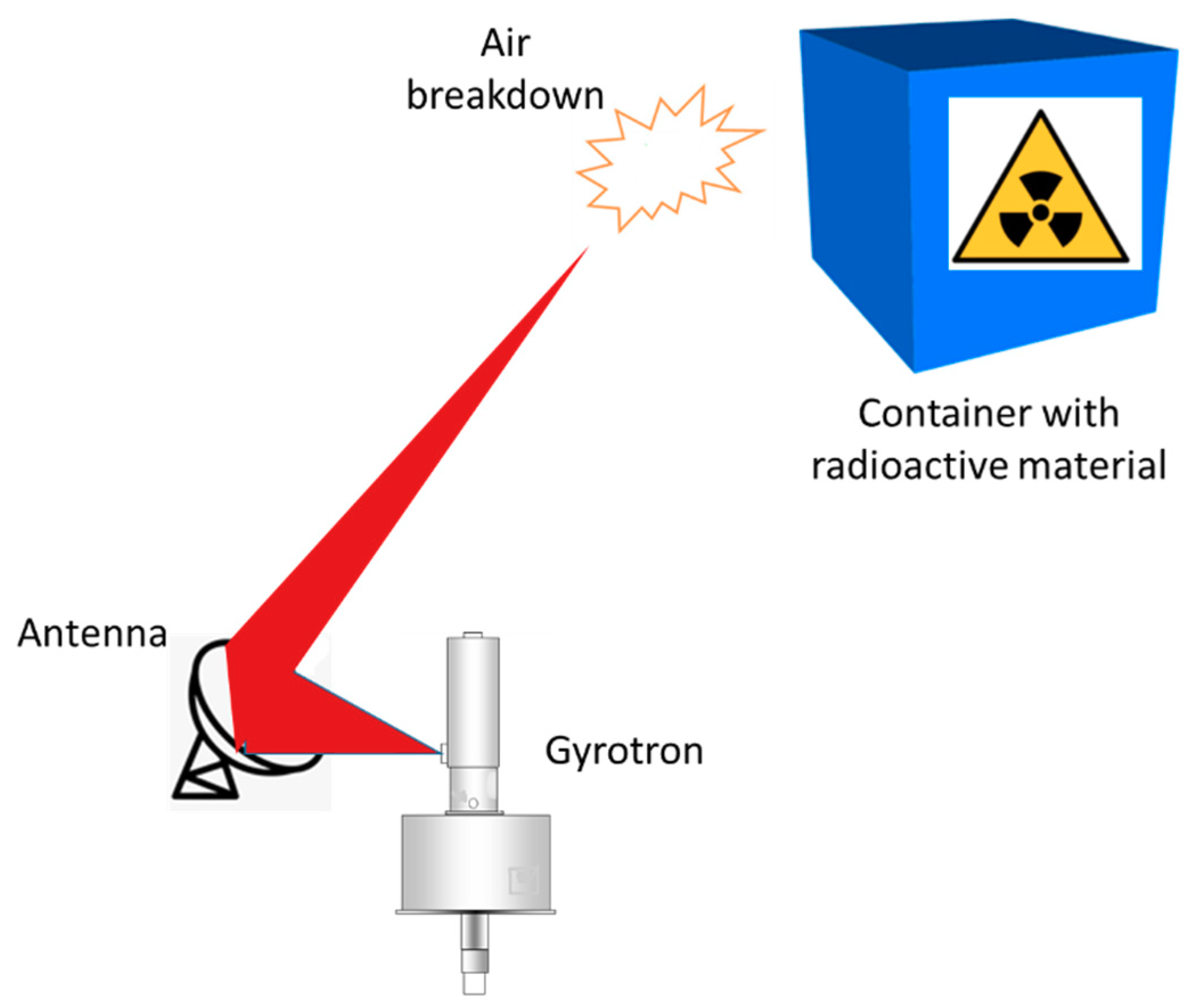
3.3. Remote Detection of Concealed Radioactive Materials

Recently, a new scheme for detecting concealed sources of ionizing radiation by observing the occurrence of a localized breakdown in atmospheric air produced by a focused electromagnetic wave whose electric field intensity surpasses the breakdown field in a small volume surrounding the radioactive material has been proposed [81]. The principle of this promising method (see Figure 8) stems from the fact that any radioactive material emits gamma rays, which ionize the surrounding air and thus produce free electrons. In this technique, the chosen volume (with dimensions on the order of a wavelength) is smaller than that of the naturally occurring free electrons. Since in the absence of radioactive materials, the ambient electron density is very low, the probability of finding a free electron that could trigger an avalanche breakdown process is such a small volume is also negligible. Therefore, observing a breakdown there indicates a presence of hidden radioactive material in the vicinity of the focused wave beam. Another specific requirement is that the pulse length of the electromagnetic wave “must exceed the avalanche breakdown time of approximately 10–200 ns and could profitably be as long as the statistical lag time in ambient air (typically, microseconds)” [81]. The analysis of the potential sources in the wavelength range 3 mm > λ > 10.6 μm has revealed that the most appropriate would be a 0.67 THz gyrotron oscillator with an output power of 200 kW and pulse duration of 10 μs or a Transversely Excited Atmospheric-Pressure (TEA) CO2 laser with 30 MW, 100 ns output pulses. The estimates presented in the cited analysis show that a system employing a 670 GHz gyrotron would have superior sensitivity, while a similar realization based on the TEA CO2 laser could have a longer range of up to 100 m.
In order to satisfy the formulated requirements, a design of a dedicated 0.67 THz gyrotron that provides a maximum output power of 300 kW (3 Joules in a pulse of 10 μs) has been proposed [82,83]. It includes a pulsed solenoid (cooled by liquid nitrogen) with a maximum magnetic field intensity of 28 T. The envisaged detection scheme of a distant breakdown is based on observing the THz signal reflected from the discharge. In the subsequent studies on this technology, many important aspects (e.g., the sensitivity and the range of the sensing) have been investigated in detail, and the components of the system have been optimized [84,85,86]. Following the above-mentioned pioneering contributions, several other research groups worldwide have joined the work on this technique [87,88]. The experimental results obtained using a 0.095 THz gyrotron suggest that detection at distances as large as 1 km should be feasible using an appropriate antenna. Based on these positive developments, it is anticipated that a fully functional system for the remote detection of concealed radioactive materias will be realized soon.

3.4. Imaging, Food Inspection, and Quality Control Using Gyrotron Radiation

Many industrial processes, most notably food production and processing due to their importance, the large volume of products, numerous serious safety, and quality control concerns could benefit enormously from non-destructive screening and inspection. Such a perspective has stimulated the development of various novel THz technologies [89,90,91] that avoid the usage of ionizing radiation (X-rays), which has a detrimental effect on the living matter. However, most of the techniques utilize broadband THz radiation (e.g., TDS (time-domain spectroscopy) systems) or laser light of low power and higher frequencies that, respectively, have small penetration depth. In this respect, the gyrotron radiation (with its sub-THz and THz frequencies and several orders of magnitude higher output powers) offers complementary/alternative solutions. Although these advantages have not been fully realized so far, a series of recent investigations have demonstrated the potential of the systems for food inspection and control based on imaging with gyrotrons [12,92,93,94,95,96].
Generally, there are two possible arrangements of THz imaging optics, namely mirror-based and lens-based [97]. An example of a system of the first kind has been proposed in [12]. It consists of a gyrotron (with an output power of about 100 W at 200 GHz and 1 W at 400 GHz, respectively), an off-axis parabolic mirror (OAP), a cylindrical parabolic mirror (CPM), a flat reflector, a normal parabolic mirror, and a pyro detector used as a THz camera. The wave beam of the gyrotron is converted into a parallel one by the OAP and then by the CPM into a line beam, which is suitable for illuminating the objects placed on a conveyor belt. The reflective imaging system comprises a flat reflector and a parabolic mirror. The experiments carried out with this system have demonstrated the feasibility of fast THz imaging for the inspection of foreign substances in food. In particular, metal and rubber have been detected at a resolution of 0.8 and 1 mm, respectively for pieces with sizes ranging from 2 to 10 mm.
In a series of works by S.-T. Han et al. (see, e.g., [92,93,94,95,96]) the capabilities of a non-invasive real-time imaging system that uses a gyrotron as a radiation source have been investigated in detail and demonstrated successfully. For instance, in [92], an active real-time imaging system employing a CW 460-GHz gyrotron and a pyroelectric array camera with 124 × 124 pixels has been presented. It can be operated in both transmission and reflection setups. The high output power of the gyrotron (16 Watts in CW operation with a 13-kV 100-mA electron beam) allows overcoming effectively the limit of the sensitivity of the array detectors at room temperature. The capabilities of this system for real-time security screening (e.g., standoff detection of concealed weapons) and identification of a foreign substance in visually opaque dry or frozen food coming out of a production line are demonstrated convincingly by images and real-time videos captured at a rate of 48 Hz (i.e., 48 frames per second) by using a built-in chopper of the camera [95]. It has been noted that by taking the videos at a lower rate and averaging over several frames, even clearer images can be obtained. This allows identifying properly the presence of objects placed inside mail envelopes using real-time videos with a running time of only several seconds. Another problem that stems from the low sensitivity of the detectors is the low signal-to-noise ratio, which leads to a poor contrast along the edges of the images. However, it has been shown that a workaround for enhancement of the contrast is to round the intensity fluctuations in several shots. Comparing the transmission and the reflection setups, it has been shown that the latter scheme provides better contrast thanks to the absence of background irradiation and suffers less from the etalon effect (which is responsible for the appearance of bright and dark interference fringes), although the width of the image is contracted due to the tilting in the configuration.
One of the latest advancements in the realization of a real-time continuous-wave terahertz (THz) line-scanned imaging based on a 1 × 240 InGaAs Schottky barrier diode (SBD) array detector with a scan velocity of 25 cm/s, a scan line length of 12 cm, and a pixel size of 0.5 × 0.5 mm2 has been presented in [98]. The system consists of the SBD array detector, a 200-GHz gyrotron source, a conveyor system, and several optical components such as a cylindrical lens (made of high-density polyethylene), cylindrical metal mirror, and a THz wire-grid polarizer, which improves the signal-to-noise ratio of the SBD array detector. Using this gyrotron-based imaging system, foreign substances (such as a paper clip) hidden under a cracker have been clearly detected with a spatial resolution of about 1 mm.
The active real-time imaging system (ARTIS) for non-destructive food inspection developed at KERI (Korea) is illustrated in Figure 9. It uses a compact gyrotron that can operate at frequencies of either 0.2 THz or 0.4 THz respectively and irradiates objects (with a width of up to 200 mm) moving on the conveyor belt with a speed of 500 mm/s. Besides its primary application, this system is adaptable to security inspection and could be used also for the detection of dangerous objects and substances [96].

3.5. Active Thermal Imaging Using Gyrotrons

Another technique that benefits from the high-output power of the sub-THz gyrotrons is the long-range sensing based on active thermal imaging [99,100]. Its principle is grounded on the fact that when beamed on the target, the millimeter-wave gyrotron radiation generates rapid transient temperature increases in different portions of the irradiated area. The time-dependent thermal field is registered using sensitive infrared (IR) imagers. In principle, this concept can be used in many situations where passive infrared imaging is currently used. The preliminary laboratory proof-of-principle experiments have demonstrated its feasibility [100]. In the measurements, an 83 GHz gyrotron with an output power of 20 kW has been used to rapidly heat various simple and complex targets. Thermal imaging with a sensitive mid-wavelength IR camera reveals clear signatures in a variety of objects illuminated at power levels of 50–200 W over an area of approximately 100 cm2. In these experiments, the target was located 1.6 m from the source, while the IR camera was located 1.2 m from the target. A variety of objects and configurations, including obscured metallic and dielectric specimens buried in sand, and covered by several layers of cloth have been detected successfully. Since temperature differences of a few hundredths of a degree can be detected, temperature changes are often visible almost immediately after the irradiation [97]. Among the anticipated potential applications is a long-range detection of explosive devices. The comparison of similar systems for active thermal imaging that use a variety of heating sources (e.g., lasers, flashlamps, and longer wavelength microwaves) shows that the millimeter-length waves provided by the sub-THz gyrotrons are particularly well suited for long-range sensing.

3.6. A High-Sensitivity Technique for Time-Resolved Imaging and Measurement of 2D Intensity Profiles of Millimeter-Wave Radiation

Recently, a novel high-sensitivity time-resolved method for imaging and measuring the spatial distribution of the intensity of millimeter waves by using visible continuum emitted by the positive column of a DC gas discharge in a mixture of cesium vapor with xenon has been proposed and demonstrated experimentally [101,102]. This imaging technique can be used for measuring the parameters of moderate-power radiation generated by various sources of millimeter waves and has been applied to the identification of the operating mode of a W-band gyrotron with a pulsed magnet as well as to the evaluation of the relative powers of some spurious modes. It has been shown also that this method can be applied to real-time imaging and non-destructive testing with a frame rate higher than 10 fps. In the experiments, two-dimensional shadow projection images of objects opaque and transparent to millimeter waves have been obtained irradiating the studied objects with pulsed watt-level millimeter waves. Moreover, it has been demonstrated that this particular type of shadowgraphy can be used for both single-shot screening (e.g., detection of concealed objects) and time-resolved imaging of time-dependent processes.

4. Conclusions and Outlook

Nowadays, we are witnessing spectacular progress in the broad fields of the terahertz science and technology stipulated by the remarkable advancements in the development of the fundamental triad: sources, detectors, and methods. Each of them stimulates both the improvement and further evolution of the other two, and together, these three basics generate a synergy effect leading to the emergence of novel devices, methods, and applications. As the most powerful sources of coherent radiation in the sub-THz and THz frequency range operating in both pulsed and CW regimes, the gyrotrons have demonstrated a remarkable potential for bridging the so-called THz gap and have opened the road to many novel applications in the fundamental physics research and applied sciences. In this review, the advantages of the gyrotrons as versatile radiation sources have been presented and illustrated with an emphasis on some of the most notable and well established as well as emerging technologies. The selected examples reveal both the current state-of-the-art of their development and bring to light the main trends for further improvements in their operational performance and functionality.
Taking into account the active research on the gyrotron development worldwide, the accumulated experience, and knowledge, we anticipate a continuation of the progress in this field. It is believed that this will lead not only to the proliferation of the existing applications that rely on the gyrotrons as radiation sources but will stimulate also the emergence of novel yet unknown approaches, methods, and devices. Definitely among them will be such that are related to imaging, sensing, quality control, etc. The ultimate goal of the present review paper was to inform the researchers working on these important applications about the capabilities of the gyrotrons as appropriate radiation sources. We hope that such an overview would be helpful in their work.

Author Contributions

T.I. and S.P.S. conceived the idea to prepare a review paper for the special issue on “Terahertz Sensing and Imaging” that presents the potential of the gyrotrons as promising radiation sources in this field. T.I., S.P.S., M.G., and S.M. provided the materials and participated equally in the discussions on the topics covered in the review. S.P.S. wrote the manuscript with support from T.I., M.G., and S.M. All authors have read and agreed to the published version of the manuscript.

Funding

This research was funded by IAP-RAS (Institute of Applied Physics of the Russian Academy of Sciences), grant number 0035-2019-0001. The APC was funded by Gyro Tech Co., Ltd., Japan.

Acknowledgments

The work has been carried out in the framework of the collaboration of the International Consortium for Development of High-Power Terahertz Science and Technology (visit: http://fir.u-fukui.ac.jp/Website_Consortium/) organized and facilitated by the Research Center for Development of Far-Infrared Region at the University of Fukui, and supported by Gyro Tech Co., Ltd., Fukui (Japan). The work of the Russian team has been supported under the project 0035-2019-0001.

Conflicts of Interest

The authors declare no conflict of interest.

References

  1. Abbott, D.; Zhang, X.-C. Scanning the Issue: T-Ray Imaging, Sensing and Retection. Proc. IEEE 2007, 95, 1509–1513. [Google Scholar] [CrossRef]
  2. Bründermann, E.; Hübers, H.-W.; Kimmitt, M.F. Terahertz Techniques; Springer: Berlin, Germany, 2012. [Google Scholar] [CrossRef]
  3. Song, H.-J.; Nagatsuma, T. Handbook of Terahertz Technologies: Devices and Applications; Pan Stanford Publishing Pte. Ltd.: Singapore, 2015. [Google Scholar]
  4. Peiponen, K.Z.; Zeitler, A.; Kuwata-Gonokami, M. (Eds.) Terahertz Spectroscopy and Imaging; Springer: Heidelberg, Germany, 2013. [Google Scholar] [CrossRef] [Green Version]
  5. Siegel, P.H. THz technology: An overview. Int. J. High Speed Electron. Syst. 2003, 13, 351–394. [Google Scholar] [CrossRef]
  6. Shibuya, T.; Kawase, K. Terahertz applications in tomographic imaging and material spectroscopy: A review. In Handbook of Terahertz Technology for Imaging, Sensing and Communications; Woodhead Publishing Series in Electronic and Optical Materials: Number 34; Saeedkia, D., Ed.; Woodhead Publishing Limited: Cambridge, UK, 2013; pp. 493–546. [Google Scholar]
  7. Son, J.-H. Terahertz bio-sensing techniques. In Handbook of Terahertz Technology for Imaging, Sensing and Communications; Woodhead Publishing Series in Electronic and Optical Materials: Number 34; Saeedkia, D., Ed.; Woodhead Publishing Limited: Cambridge, UK, 2013; pp. 217–230. [Google Scholar]
  8. Yin, X.; Ng, B.W.-H.; Abbott, D. Terahertz Imaging for Biomedical Applications: Pattern Recognition and Tomographic Reconstruction; Springer: New York, NY, USA, 2012. [Google Scholar] [CrossRef]
  9. Wang, S.; Ferguson, B.; Abbott, D. T-ray Imaging and Tomography. J. Biol. Phys. 2003, 29, 247–256. [Google Scholar] [CrossRef] [PubMed]
  10. Pickwell, E.; Wallace, V.P. Biomedical applications of terahertz technology (Topical Review). J. Phys. D Appl. Phys. 2006, 39, R301–R310. [Google Scholar] [CrossRef]
  11. Shen, Y.-C.; Jin, B.B. Terahertz applications in the pharmaceutical industry. In Handbook of Terahertz Technology for Imaging, Sensing and Communications; Woodhead Publishing Series in Electronic and Optical Materials: Number 34; Saeedkia, D., Ed.; Woodhead Publishing Limited: Cambridge, UK, 2013; pp. 579–614. [Google Scholar]
  12. Lee, W.-H.; Lee, W. Food inspection system using Terahertz imaging. Microw. Opt. Technol. Lett. 2014, 56, 1211–1214. [Google Scholar] [CrossRef]
  13. Afsah-Hejri, L.; Hajeb, P.; Ara, P.; Ehsani, R.J. A Comprehensive Review on Food Applications of Terahertz Spectroscopy and Imaging. Compr. Rev. Food Sci. Food Saf. 2019, 18, 1563–1621. [Google Scholar] [CrossRef]
  14. Chen, H.M.; Lee, S.; Rao, R.M.; Slamani, M.-L.; Varshney, P.K. Imaging for concealed weapon detection: A tutorial overview of development in imaging sensors and processing. IEEE Signal Process. Mag. 2005, 22, 52–61. [Google Scholar] [CrossRef]
  15. Lewis, R.A. A review of terahertz sources. J. Phys. D Appl. Phys. 2014, 47, 374001. [Google Scholar] [CrossRef]
  16. Sizov, F.; Rogalski, A. THz detectors. Prog. Quantum Electron. 2010, 34, 278–347. [Google Scholar] [CrossRef]
  17. Dhillon, S.S.; Vitiello, M.S.; Linfield, E.H.; Davies, A.G.; Hoffmann, M.C.; Booske, J.; Paoloni, C.; Gensch, M.; Weightman, P.; Williams, G.P.; et al. The 2017 terahertz science and technology roadmap. J. Phys. D Appl. Phys. 2017, 50, 043001. [Google Scholar] [CrossRef]
  18. Müller, A.S.; Schwarz, M. Accelerator-Based THz Radiation Sources. In Synchrotron Light Sources and Free-Electron Lasers; Jaeschke, E., Khan, S., Schneider, J., Hastings, J., Eds.; Springer: Cham, Switzerland, 2016; pp. 83–117. [Google Scholar] [CrossRef]
  19. Booske, J.H. Plasma physics and related challenges of millimeter wave-to-terahertz and high power microwave generation. Phys. Plasmas 2008, 15, 055502. [Google Scholar] [CrossRef] [Green Version]
  20. Idehara, T.; Saito, T.; Ogawa, I.; Mitsudo, S.; Tatematsu, Y.; Sabchevski, S. The potential of the gyrotrons for development of the sub-terahertz and the terahertz frequency range—A review of novel and prospective applications. Thin Solid Films 2008, 517, 1503–1506. [Google Scholar] [CrossRef]
  21. Thumm, M. State-of-the-art of high power gyro-devices and free electron masers. J. Infrared Millim. Terahertz Waves 2020, 41, 1–140. [Google Scholar] [CrossRef] [Green Version]
  22. Kumar, N.; Singh, U.; Singh, T.P.; Sinha, A.K. A Review on the Applications of High Power, High Frequency Microwave Source: Gyrotron. J. Fusion Energy 2011, 30, 257–276. [Google Scholar] [CrossRef]
  23. Idehara, T.; Mitsudo, S.; Sabchevski, S.; Glyavin, M.; Ogawa, I. Gyrotron FU series—Current status of development and applications. Int. J. Vac. 2001, 62, 123–132. [Google Scholar] [CrossRef]
  24. Temkin, R.J. Development of terahertz gyrotrons for spectroscopy at MIT. Terahertz Sci. Technol. 2014, 7, 1–9. [Google Scholar] [CrossRef]
  25. Glyavin, M.Y.; Idehara, T.; Sabchevski, S.P. Development of THz Gyrotrons at IAP RAS and FIR UF and Their Applications in Physical Research and High-Power THz Technologies. IEEE Trans. Terahertz Sci. Technol. 2015, 5, 788–797. [Google Scholar] [CrossRef]
  26. Idehara, T.; Sabchevski, S.P. Development and Application of Gyrotrons at FIR UF. IEEE Trans. Plasma Sci. 2018, 46, 2452–2459. [Google Scholar] [CrossRef]
  27. Idehara, T.; Ogawa, I.; Shimizu, Y.; Tatsukawa, T. Higher Harmonic Operations of Submillimeter Wave Gyrotrons (Gyrotron FU Series). Int. J. Infrared Millim. Waves 1998, 19, 803–816. [Google Scholar] [CrossRef]
  28. Hornstein, M.K.; Bajaj, V.S.; Griffin, R.G.; Temkin, R.J. Continuous-wave operation of a 460-GHz second harmonic gyrotron oscillator. IEEE Trans. Plasma Sci. 2006, 34, 524–533. [Google Scholar] [CrossRef] [Green Version]
  29. Kartikeyan, M.V.; Borie, E.; Thumm, M. A 250 GHz, 50 W, CW second harmonic gyrotron. Int. J. Infrared Millim. Waves 2007, 28, 611–619. [Google Scholar] [CrossRef]
  30. Morozkin, M.V.; Glyavin, M.Y.; Denisov, G.G.; Luchinin, A.G. A high-efficiency second-harmonic gyrotron with a depressed collector. Int. J. Infrared Millim. Waves 2008, 29, 1004–1010. [Google Scholar] [CrossRef]
  31. Saito, T.; Yamada, N.; Ikeuti, S.; Ogasawara, S.; Tatematsu, Y.; Ikeda, R.; Ogawa, I.; Idehara, T.; Manuilov, V.N.; Shimozuma, T.; et al. Generation of high power sub-terahertz radiation from a gyrotron with second harmonic oscillation. Phys. Plasmas 2012, 19, 063106. [Google Scholar] [CrossRef] [Green Version]
  32. Tatematsu, Y.; Yamaguchi, Y.; Idehara, T.; Kawase, T.; Ichioka, R.; Ogawa, I.; Saito, T.; Fujiwara, T. Development of second harmonic gyrotrons, Gyrotron FU CW GII and Gyrotron FU CW GIII, equipped with internal mode converters. J. Infrared Millim. Terahertz Waves 2014, 35, 169–178. [Google Scholar] [CrossRef]
  33. Bratman, V.L.; Kalynov, Y.K.; Manuilov, V.N. Large-orbit gyrotron operation in the terahertz frequency range. Phys. Rev. Lett. 2009, 102, 245101. [Google Scholar] [CrossRef] [PubMed]
  34. Kalynov, Y.; Manuilov, V.; Fiks, A.; Zavolskiy, N. Powerful continuous-wave sub-terahertz electron maser operating at the 3rd cyclotron harmonic. Appl. Phys. Lett. 2019, 114, 213502. [Google Scholar] [CrossRef]
  35. Idehara, T.; Ogawa, I.; Mitsudo, S.; Iwata, Y.; Watanabe, S.; Itakura, Y.; Ohashi, K.; Kobayashi, H.; Yokoyama, T.; Zapevalov, V.E.; et al. A high harmonic gyrotron with an axis-encircling electron beam and a permanent magnet. IEEE Trans. Plasma Sci. 2004, 32, 903–909. [Google Scholar] [CrossRef]
  36. Zapevalov, V.E.; Manuilov, V.N.; Malygin, O.V.; Tsimring, S.E. High-power twin-beam gyrotrons operating at the second gyrofrequency harmonic. Radiophys. Quantum Electron. 1994, 37, 237–240. [Google Scholar] [CrossRef]
  37. Glyavin, M.Y.; Luchinin, A.G.; Golubiatnikov, G.Y. Generation of 1.5-kW, 1-THz Coherent Radiation from a Gyrotron with a Pulsed Magnetic Field. Phys. Rev. Lett. 2008, 100, 015101. [Google Scholar] [CrossRef]
  38. Idehara, T.; Ogawa, I.; Mori, H.; Kobayashi, S.; Mitsudo, S.; Saito, T. A THz Gyrotron FU CW III with a 20 T superconducting magnet. J. Plasma Fusion Res. Ser. 2009, 8, 1508–1511. [Google Scholar]
  39. Glyavin, M.Y.; Ginzburg, N.S.; Goldenberg, A.L.; Luchinin, A.G.; Denisov, G.G.; Manuilov, V.N.; Vladimir, E.; Zapevalov, V.E.; Zotova, I.V. THz Gyrotrons: Status and Possible Optimizations. Terahertz Sci. Technol. 2012, 5, 67–77. [Google Scholar] [CrossRef]
  40. Han, S.T.; Griffin, R.G.; Hu, K.N.; Joo, C.G.; Joye, C.D.; Mastovsky, I.; Shapiro, M.A.; Sirigiri, J.R.; Temkin, R.J.; Torrezan, A.C.; et al. Continuous-wave Submillimeter-wave Gyrotrons. Proc. SPIE Int. Soc. Opt. Eng. 2006, 6373. [Google Scholar] [CrossRef]
  41. Han, S.T.; Griffin, R.G.; Hu, K.N.; Joo, C.G.; Joye, C.D.; Sirigiri, J.R.; Temkin, R.J.; Torrezan, A.C.; Woskov, P.P. Spectral characteristics of a 140-GHz long-pulsed gyrotron. IEEE Trans. Plasma Sci. 2007, 35, 559–564. [Google Scholar] [CrossRef] [PubMed]
  42. Glyavin, M.Y.; Chirkov, A.V.; Denisov, G.G.; Fokin, A.P.; Kholoptsev, V.V.; Kuftin, A.N.; Luchinin, A.G.; Golubyatnikov, G.Y.; Malygin, V.I.; Morozkin, M.V.; et al. Experimental tests of a 263 GHz gyrotron for spectroscopic applications and diagnostics of various media. Rev. Sci. Instrum. 2015, 86, 054705. [Google Scholar] [CrossRef] [PubMed]
  43. Alberti, S.; Braunmueller, F.; Tran, T.M.; Hogge, J.-P.; Genoud, J.; Tran, M.Q. High-Power THz-Waves using gyrotrons: New physics results. Terahertz Sci. Technol. 2014, 7, 23–38. [Google Scholar]
  44. Idehara, T.; Mitsudo, S.; Ogawa, I. Development of High-Frequency, Highly Stable Gyrotrons as Millimeter to Submillimeter Wave Radiation Sources. IEEE Trans. Plasma Sci. 2004, 32, 910–916. [Google Scholar] [CrossRef]
  45. Fokin, A.; Tsvetkov, A.; Manuilov, V.; Sedov, A.; Bozhkov, V.; Genneberg, V.; Movshevich, B.; Glyavin, M. Control of sub-terahertz gyrotron frequency by modulation-anode voltage: Comparison of theoretical and experimental results. Rev. Sci. Instrum. 2019, 90, 124705. [Google Scholar] [CrossRef]
  46. Ueda, K.; Matsuki, Y.; Fujiwara, T.; Tatematsu, Y.; Ogawa, I.; Idehara, T. Further Characterization of 394-GHz Gyrotron FU CW GII with Additional PID Control System for 600-MHz DNP-SSNMR Spectroscopy. J. Infrared Millim. Terahertz Waves 2016, 37, 825–836. [Google Scholar] [CrossRef]
  47. Khutoryan, E.M.; Idehara, T.; Kuleshov, A.N.; Tatematsu, Y.; Yamaguchi, Y.; Matsuki, Y.; Fujiwara, T. Stabilization of Gyrotron Frequency by PID Feedback Control on the Acceleration Voltage. J. Infrared Millim. Terahertz Waves 2015, 36, 1157–1163. [Google Scholar] [CrossRef]
  48. Khutoryan, E.M.; Idehara, T.; Kuleshov, A.N.; Tatematsu, Y.; Yamaguchi, Y.; Matsuki, Y.; Fujiwara, T. Simultaneous Stabilization of Gyrotron Frequency and Power by PID Double Feedback Control on the Acceleration and Anode Voltages. J. Infrared Millim. Terahertz Waves 2017, 38, 813–823. [Google Scholar] [CrossRef]
  49. Fokin, A.; Glyavin, M.; Golubiatnikov, G.; Lubyako, L.; Morozkin, M.; Movschevich, B.; Tsvetkov, A.; Denisov, G. High-power sub-terahertz source with a record frequency stability at up to 1 Hz. Sci. Rep. 2018, 8, 4317. [Google Scholar] [CrossRef] [PubMed] [Green Version]
  50. Brand, F.G. Tunable gyrotrons. In Infrared and Millimeter Waves; Button, K.J., Ed.; Academic Press: New York, NY, USA, 1985; Volume 14, pp. 371–408. [Google Scholar]
  51. Sabchevski, S.P.; Idehara, T. A Numerical Study on Finite-Bandwidth Resonances of High-Order Axial Modes (HOAM) in a Gyrotron Cavity. J. Infrared Millim. Terahertz Waves 2015, 36, 628–653. [Google Scholar] [CrossRef] [Green Version]
  52. Sabchevski, S.; Idehara, T. Resonant Cavities for Frequency Tunable Gyrotrons. Int. J. Infrared Millim. Waves 2008, 29, 1–22. [Google Scholar] [CrossRef]
  53. Hong, K.D.; Brand, G.F.; Idehara, T. A 150–600 GHz step-tunable gyrotron. J. Appl. Phys. 1993, 74, 5250–5258. [Google Scholar] [CrossRef]
  54. Idehara, T.; Shimizu, Y.; Ogawa, I.; Tatsukawa, T.; Brand, G.F. Rapid frequency step-switching in submillimeter wave gyrotrons (Gyrotrons FU III and FU IV). Phys. Plasmas 1999, 6, 2613–2617. [Google Scholar] [CrossRef]
  55. Zapevalov, V.E.; Bogdashov, A.A.; Chirkov, A.V.; Denisov, G.G.; Kuftin, A.N.; Lygin, V.K.; Moiseev, M.A. Optimization of the frequency step tunable 105–170 GHz 1 MW gyrotron prototype. In Proceedings of the Twenty Seventh International Conference on Infrared and Millimeter Waves, San Diego, CA, USA, 26 September 2002; pp. 1–2. [Google Scholar] [CrossRef]
  56. Samartsev, A.; Avramidis, K.A.; Gantenbein, G.; Dammertz, G.; Thumm, M.; Jelonnek, J. Efficient Frequency Step-Tunable Megawatt-Class D-Band Gyrotron. IEEE Trans. Electron Devices 2015, 62, 327–2332. [Google Scholar] [CrossRef]
  57. Hornstein, M.K.; Bajaj, V.S.; Griffin, R.G.; Kreischer, K.E.; Mastovsky, I.; Shapiro, M.A.; Sirigiri, J.R.; Temkin, R.J. Second harmonic operation at 460 GHz and broadband continuous frequency tuning of a gyrotron oscillator. IEEE Trans. Electron Devices 2005, 52, 798–807. [Google Scholar] [CrossRef] [Green Version]
  58. Chang, T.H.; Idehara, T.; Ogawa, I.; Agusu, L.; Kobayashi, S. Frequency tunable gyrotron using backward wave components. J. Appl. Phys. 2009, 105, 063304. [Google Scholar] [CrossRef]
  59. Torrezan, A.C.; Han, S.-T.; Mastovsky, I.; Shapiro, M.A.; Sirigiri, J.R.; Temkin, R.J.; Barnes, A.B.; Griffin, R.G. Continuous—Wave Operation of a Frequency-Tunable 460-GHz Second-Harmonic Gyrotron for Enhanced Nuclear Magnetic Resonance. IEEE Trans. Plasma Sci. 2010, 38, 1150–1159. [Google Scholar] [CrossRef]
  60. Idehara, T.; Kosuga, K.; Agusu, L.; Ikeda, R.; Ogawa, I.; Saito, T.; Matsuki, Y.; Ueda, K.; Fujiwara, T. Continuously Frequency Tunable High Power Sub-THz Radiation Source-Gyrotron FU CW VI for 600-MHz DNP-NMR Spectroscopy. J. Infrared Millim. Terahertz Waves 2010, 31, 775–790. [Google Scholar] [CrossRef]
  61. Matsuki, Y.; Idehara, T.; Fukazawa, J.; Fujiwara, T. Advanced instrumentation for DNP-enhanced MAS NMR for higher magnetic fields and lower temperatures. J. Magn. Resonance 2016, 264, 107–115. [Google Scholar] [CrossRef] [PubMed] [Green Version]
  62. Thankamony, A.S.L.; Wittmann, J.J.; Kaushik, M.; Corzilius, B. Dynamic nuclear polarization for sensitivity enhancement in modern solid-state NMR. Prog. Nucl. Magn. Resonance Spectrosc. 2017, 102, 120–195. [Google Scholar] [CrossRef] [PubMed]
  63. Yoon, D.; Soundararajan, M.; Cuanillon, P.H.; Braunmueller, F.; Alberti, S.; Ansermet, J.-P.H. Dynamic nuclear polarization by frequency modulation of a tunable gyrotron of 260 GHz. J. Magn. Resonance 2016, 262, 62–67. [Google Scholar] [CrossRef] [PubMed] [Green Version]
  64. Idehara, T.; Pereyaslavets, M.; Nishida, N.; Yoshida, K.; Ogawa, I. Frequency Modulation in a Submillimeter-Wave Gyrotron. Phys. Rev. Lett. 1998, 81, 1973–1976. [Google Scholar] [CrossRef]
  65. Idehara, T.; Khutoryan, E.M.; Tatematsu, Y.; Yamaguchi, Y.; Kuleshov, A.N.; Dumbrajs, O.; Matsuki, Y.; Fujiwara, T. High-speed frequency modulation of a 460-GHz gyrotron for enhancement of 700-MHz DNP-NMR spectroscopy. J. Infrared Millim. Terahertz Waves 2015, 36, 819–829. [Google Scholar] [CrossRef]
  66. Becerra, L.R.; Gerfen, G.J.; Temkin, R.J.; Singel, D.J.; Griffin, R. Dynamic Nuclear Polarization with a Cyclotron Resonance Maser at 5 T. Phys. Rev. Lett. 1993, 71, 3561–3564. [Google Scholar] [CrossRef]
  67. Idehara, T.; Sabchevski, S. Development and Applications of High-Frequency Gyrotrons in FIR FU Covering the sub-THz to THz Range. J. Infrared Millim. Terahertz Waves 2012, 33, 667–694. [Google Scholar] [CrossRef]
  68. Idehara, T.; Sabchevski, S.P. Gyrotrons for High-Power Terahertz Science and Technology at FIR UF. J. Infrared Millim. Terahertz Waves 2017, 38, 62–86. [Google Scholar] [CrossRef] [Green Version]
  69. Bruker Announces World’s First 1.2 GHz High-Resolution Protein NMR Data. Available online: https://ir.bruker.com/press-releases/press-release-details/2019/Bruker-Announces-Worlds-First-12-GHz-High-Resolution-Protein-NMR-Data/default.aspx (accessed on 14 December 2019).
  70. Idehara, T.; Glyavin, M.; Kuleshov, A.; Sabchevski, S.; Manuilov, V.; Zaslavsky, V.; Zotova, I.; Sedov, A. A novel THz-band double-beam gyrotron for high-field DNP-NMR spectroscopy. Rev. Sci. Instrum. 2017, 88, 094708. [Google Scholar] [CrossRef]
  71. Mitsudo, S.; Glyavin, M.; Khutoryan, E.; Bandurkin, I.; Saito, T.; Ishikawa, Y.; Manuilov, V.; Zotova, I.; Fedotov, A.; Kuleshov, A.; et al. An Experimental Investigation of a 0.8 THz Double-Beam Gyrotron. J. Infrared Millim. Terahertz Waves 2019, 40, 1114–1128. [Google Scholar] [CrossRef]
  72. Mitsudo, S.; Umegaki, C.; Hiiragi, K.; Narioka, M.; Fujii, Y.; Tatematsu, Y. Development of a millimeter wave pulsed ESR system by using a gyrotron as a light source. In Proceedings of the 2016 41st International Conference on Infrared, Millimeter, and Terahertz waves (IRMMW-THz), Copenhagen, Denmark, 25–30 September 2016; p. 1. [Google Scholar] [CrossRef]
  73. Asai, S.; Yamazaki, T.; Miyazaki, A.; Suehara, T.; Namba, T.; Kobayashi, T.; Saito, H.; Idehara, T.; Ogawa, I.; Sabchevski, S. Direct Measurement of Positronium Hyper Fine Structure—A New Horizon of Precision Spectroscopy Using Gyrotrons. J. Infrared Millim. Terahertz Waves 2012, 3, 766–776. [Google Scholar] [CrossRef]
  74. Yamazaki, T.; Miyazaki, A.; Suehara, T.; Namba, T.; Asai, S.; Kobayashi, T.; Saito, H.; Ogawa, I.; Idehara, T.; Sabchevski, S. Direct observation of the hyperfine transition of ground-state positronium. Phys. Rev. Lett. 2012, 108, 253401. [Google Scholar] [CrossRef] [PubMed] [Green Version]
  75. Rogalev, A.; Goulon, J.; Goujon, J.; Wilhelm, F.; Ogawa, I.; Idehara, T. X-ray detected magnetic resonance at sub-THz frequencies using a high-power gyrotron source. J. Infrared Millim. Terahertz Waves 2012, 33, 777–793. [Google Scholar] [CrossRef]
  76. Goulon, J.; Rogalev, A.; Wilhelm, F.; Goujon, G. X-ray detected magnetic resonance: A new spectroscopic tool. In Magnetism and Synchrotron Radiation; Beaurepaire, E., Bulou, H., Scheurer, F., Jean-Paul, K., Eds.; Springer: Berlin/Heidelberg, Germany, 2010; pp. 191–222. [Google Scholar] [CrossRef]
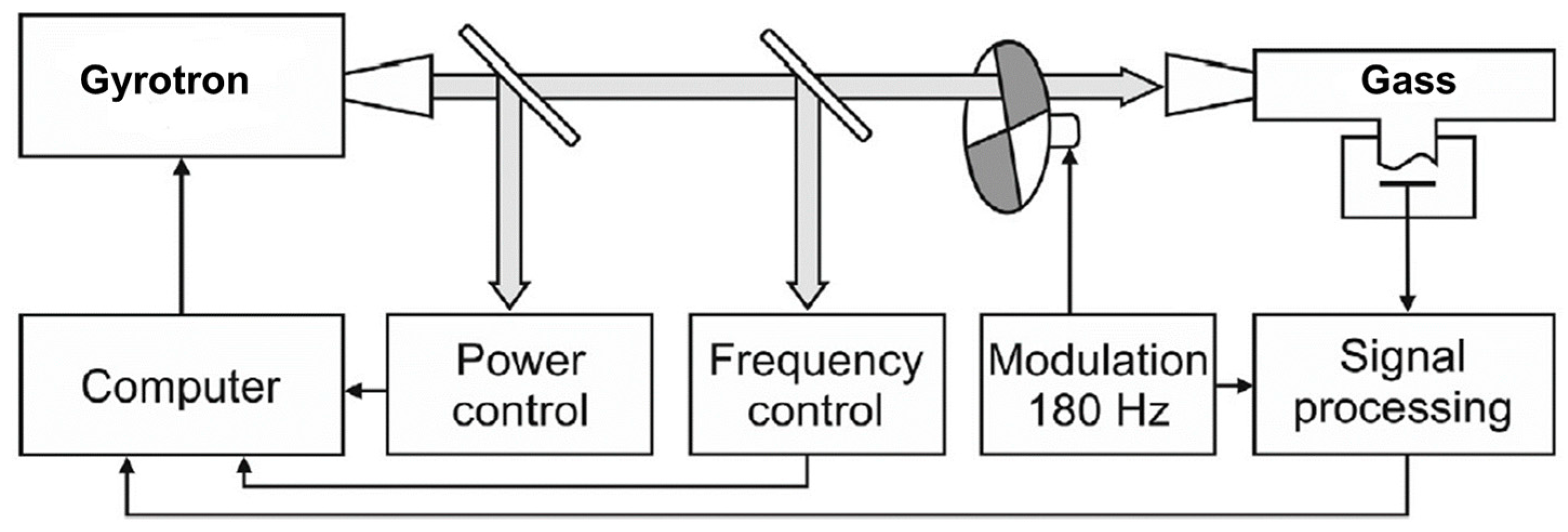
  77. Koshelev, M.A.; Tsvetkov, A.I.; Morozkin, M.V.; Glyavin, M.Y.; Tretyakov, M.Y. Molecular gas spectroscopy using radioacoustic detection and high-power coherent subterahertz radiation sources. J. Mol. Spectrosc. 2017, 331, 9–16. [Google Scholar] [CrossRef]
  78. Manheimer, W. A role for high power millimeter wave sources in atmospheric remote sensing. In Proceedings of the International Conference on Plasma Sciences (ICOPS), Vancouver, BC, Canada, 7–9 June 1993; p. 88. [Google Scholar] [CrossRef]
  79. Novel Gyro-TWA Amplifier for High Power Mm-Wave Radar Remote Sensing. Available online: https://gtr.ukri.org/projects?ref=ST%2FK006673%2F1 (accessed on 14 December 2019).
  80. He, W.; Donaldson, C.R.; Zhang, L.; McElhinney, F.; Yin, H.; Garner, J.R.; Ronald, K.; Cross, A.W.; Phelps, A.D.R. Experimental test of a W-band gyro-TWA for cloud radar applications. In Proceedings of the 2016 46th European Microwave Conference (EuMC), London, UK, 4–6 October 2016; pp. 1099–1102. [Google Scholar] [CrossRef] [Green Version]
  81. Granatstein, V.L.; Nusinovich, G.S. Detecting excess ionizing radiation by electromagnetic breakdown of air. J. Appl. Phys. 2010, 108, 063304. [Google Scholar] [CrossRef]
  82. Nusinovich, G.S.; Pu, R.; Antonsen, T.M.; Sinitsyn, O.V.; Rodgers, J.; Mohamed, A.; Silverman, J.; Al-Sheikhly, M.; Dimant, Y.S.; Milikh, G.M.; et al. Development of THz-range gyrotrons for detection of concealed radioactive materials. J. Infrared Millim. Terahertz Waves 2011, 32, 380–402. [Google Scholar] [CrossRef]
  83. Glyavin, M.Y.; Luchinin, A.G.; Bogdashov, A.A.; Manuilov, V.N.; Morozkin, M.V.; Rodin, Y.V.; Denisov, G.G.; Kashin, D.; Rogers, G.; Romero-Talamas, C.A.; et al. Experimental Study of the Pulsed Terahertz Gyrotron with Record-Breaking Power and Efficiency Parameters. Radiophys. Quantum Electron. 2014, 56, 497–507. [Google Scholar] [CrossRef]
  84. Nusinovich, G.S.; Sprangle, P.; Romero-Talamas, C.A.; Granatstein, V.L. Range, resolution and power of THz systems for remote detection of concealed radioactive materials. J. Appl. Phys. 2011, 109, 083303. [Google Scholar] [CrossRef]
  85. Nusinovich, G.S.; Sprangle, P.; Semenov, V.E.; Dorozhkina, D.S.; Glyavin, M.Y. On the sensitivity of terahertz gyrotron based systems for remote detection of concealed radioactive materials. J. Appl. Phys. 2012, 111, 124912. [Google Scholar] [CrossRef]
  86. Glyavin, M.Y.; Luchinin, A.G.; Manuilov, V.N.; Morozkin, M.V.; Bogdashov, A.A.; Gachev, I.G.; Sedov, A.S.; Pu, P.; Nusinovich, G.S.; Granatshtein, V.L. Development of a high-power pulsed subterahertz gyrotron for remote detection of sources of ionizing radiation. Radiophys. Quantum Electron. 2012, 54, 600–608. [Google Scholar] [CrossRef]
  87. Kumar, N.; Singh, U.; Kumar, A.; Sinha, A.K. A Feasibility Study of Beam-Wave Interaction in 670 GHz Gyrotron for Radioactive Material Detection Application. Jpn. J. Appl. Phys. 2012, 51, 076705. [Google Scholar] [CrossRef]
  88. Kim, D.; Yu, D.; Sawant, A.; Choe, M.S.; Lee, I.; Kim, S.G.; Choi, E. Remote detection of radioactive material using high-power pulsed electromagnetic radiation. Nat. Commun. 2017, 8, 15394. [Google Scholar] [CrossRef] [PubMed] [Green Version]
  89. Kawase, M. Application of Terahertz Waves to Food Science. Rev. Food Sci. Technol. Res. 2012, 18, 601–609. [Google Scholar] [CrossRef] [Green Version]
  90. Lee, Y.K.; Choi, S.W.; Han, S.T.; Woo, D.H.; Chun, H.S. Detection of foreign bodies in foods using continuous wave terahertz imaging. J. Food Prot. 2012, 75, 179–183. [Google Scholar] [CrossRef] [PubMed]
  91. Ren, A.; Zahid, A.; Fan, D.; Yang, X.; Imran, M.A.; Alomainy, A.; Abbasi, Q.H. State-of-the-art in terahertz sensing for food and water security–A comprehensive review. Trends Food Sci. Technol. 2019, 85, 241–251. [Google Scholar] [CrossRef] [Green Version]
  92. Han, S.-T.; Torrezan, A.C.; Sirigiri, J.R.; Shapiro, M.A.; Temkin, R.J. Active real-time imaging system employed with a CW 460-GHz gyrotron and a pyroelectric array camera. In Proceedings of the 34th International Conference on Infrared, Millimeter, and Terahertz Waves (IRMMW-THz 2009), Busan, Korea, 21–25 September 2009; pp. 1–2. [Google Scholar] [CrossRef]
  93. Han, S.T.; Park, W.K.; Chun, H.S. Development of a compact sub-terahertz gyrotron and its application to t-ray real-time imaging for food inspection. In Proceedings of the 37th International Conference on Infrared, Millimeter, and Terahertz Waves (IRMMW-THz 2012), Wollongong, Australia, 23–28 September 2012. [Google Scholar] [CrossRef]
  94. Han, S. Compact sub-THz gyrotrons for real-time T-ray imaging. In Proceedings of the 2013 IEEE 14th International Vacuum Electronics Conference (IVEC), Paris, France, 21–23 May 2013; pp. 3–4. [Google Scholar] [CrossRef]
  95. Han, S.T.; Torrezan, A.C.; Sirigiri, J.R.; Shapiro, M.A.; Temkin, R.J. Real-time, T-ray imaging using a sub-terahertz gyrotron. J. Korean Phys. Soc. 2012, 60, 1857–1861. [Google Scholar] [CrossRef]
  96. Han, S.T.; Lee, W.J.; Park, K.S.; Choi, S.W.; Yoon, J.H.; Yoo, J.S. Application of T-ray gyrotron developed for real-time non-destructive inspection to enhanced regeneration of cells. In Proceedings of the 2015 40th International Conference on Infrared, Millimeter, and Terahertz waves (IRMMW-THz 2015), Hong Kong, China, 23–28 August 2015; pp. 1–2. [Google Scholar] [CrossRef]
  97. Kim, G.J.; Kim, J.I.; Jeon, S.G.; Kim, J.; Park, K.K.; Oh, C.H. Enhanced continuous-wave terahertz imaging with a horn antenna for food inspection. J. Infrared Millim. Terahertz Waves 2012, 33, 657–664. [Google Scholar] [CrossRef]
  98. Han, S.P.; Ko, H.; Kim, N.; Lee, W.H.; Moon, K.; Lee, I.M.; Lee, E.S.; Lee, D.H.; Lee, W.; Han, S.T.; et al. Real-time continuous-wave terahertz line scanner based on a compact 1× 240 InGaAs Schottky barrier diode array detector. Opt. Express 2014, 22, 28977–28983. [Google Scholar] [CrossRef]
  99. Hubbard, R.; Fliflet, A.; Smith, G.; Andreadis, T.; Hornstein, M.K.; Lombardi, M.; Bowles, J.; Gold, S.; Lewis, D.; Kidwell, D. Long-range thermal imaging using a millimeter-wave source. In Proceedings of the 33rd IEEE International Conference on Plasma Science (ICOPS 2006), Traverse City, MI, USA, 4–8 June 2006; p. 352. [Google Scholar] [CrossRef]
  100. Hornstein, M.K.; Hubbard, R.F.; Smith, G.; Fliflet, A.W.; Lombardi, M.; Gold, S.H.; Lewis, D., III; Andreadis, T.D. Demonstration experiments for active thermal imaging using a millimeter-wave source (ATIMS). In Proceedings of the 33rd IEEE International Conference on Plasma Science (ICOPS 2006), Traverse City, MI, USA, 4–8 June 2006. [Google Scholar] [CrossRef]
  101. Gitlin, M.S.; Glyavin, M.Y.; Fedotov, A.E.; Tsvetkov, A.I. Imaging of Spatial Distributions of the Millimeter Wave Intensity by Using the Visible Continuum Radiation from a Discharge in a Cs–Xe Mixture. Part II: Demonstration of Application Capabilities of the Technique. Plasma Phys. Rep. 2017, 43, 778–791. [Google Scholar] [CrossRef]
  102. Gitlin, M.S.; Golovanov, V.V.; Spivakov, A.G.; Tsvetkov, A.I.; Zelenogorskiy, V.V. Time-resolved imaging of millimeter waves using visible continuum from the positive column of a Cs–Xe dc discharge. J. Appl. Phys. 2010, 107, 063301. [Google Scholar] [CrossRef]
Figure 1. Gyrotron interaction illustrated by the Brillouine diagram.
Applsci 10 00980 g001
Figure 2. Schematic structure of a generic gyrotron and its components: 1—magnetron injection gun (MIG); 2—additional gun coils; 3—beam tunnel and compression region; 4—main coils of the superconducting magnet; 5—gyrotron cavity resonator; 6—launcher of the internal mode converter; 7—system of mirrors of the internal mode converter; 8—Gaussian wave beam; 9—output vacuum window; 10—helical electron beam; 11—water-cooled collector of the spent electron beam; 12—magnetic sweeping coils for smearing the spent electron beam.
Applsci 10 00980 g002
Figure 3. Photos of some of the gyrotrons of the FU CW series developed as radiation sources for spectroscopic studies.
Applsci 10 00980 g003
Figure 4. 0.8 THz double-beam gyrotron with a 15 T cryo-free superconducting magnet at FIR UF.
Applsci 10 00980 g004
Figure 5. Experimental setup for the measurement of the hyperfine splitting of positronium (Ps-HFS).
Applsci 10 00980 g005
Figure 6. Schematics of the pump-and-probe technique for X-ray detected magnetic resonance (XDMR) spectroscopy.
Applsci 10 00980 g006
Figure 7. Simplified diagram of a radioacoustic detection (RAD) spectrometer using gyrotron as a radiation source spectroscopy.
Applsci 10 00980 g007
Figure 8. Schematics of the remote detection of radioactive material hidden in a container.
Applsci 10 00980 g008
Figure 9. (a) Gyrotron-based active real-time imaging system for food inspection; (b) shadow images captured from the video taken by the line array detectors placed beneath the conveyor belt. Images courtesy of S.-T. Han.
Applsci 10 00980 g009
Table 1. Main advantages of the gyrotrons as versatile radiation sources in the terahertz (THz) region.
Characteristic Features of the Gyrotrons and Their Radiation
High-power (from Watts to kW) 1 radiation in both pulsed and CW (continuous wave) regimes.
Coherent radiation with stable spectral characteristics (narrow spectral line width; small down- and up-shift of the frequency during the pulse and long operation times; possibilities for phase locking).
Stable output parameters (power and frequency) through appropriate stabilization (e.g., PID control)
Step-wise and smooth continuous frequency tunability in wide frequency bands.
Possibility to modulate the output power and frequency.
Possibility to deliver Gaussian beam output using internal or external quasi-optical converters.
Possibility for transmission of the generated radiation by waveguides (e.g., corrugated waveguides with low losses) or quasi-optical system of reflectors and phase-correcting mirrors.
Possibility to focus and steer the generated wave beam by quasi-optical elements.
1 Here, we omit the most powerful gyrotrons for the heating of fusion plasma that already reached megawatt levels of the output power, since this prominent application is outside the scope of the present review.

