Article

Optimum Design of Sunken Reinforced Enclosures under Buckling Condition

by
Mostafa Omidi Bidgoli
1,*,
Kazem Reza Kashyzadeh
2,
Seyed Saeid Rahimian Koloor
3,4,*,
Michal Petrů
3 and
Nima Amiri
5
1
Department of Mechanical Engineering, Islamic Azad University, Badroud Branch, 87641-36545 Badroud, Iran
2
Department of Mechanical and Instrumental Engineering, Academy of Engineering, Peoples’ Friendship University of Russia (RUDN University), 6 Miklukho-Maklaya Street, 117198 Moscow, Russia
3
Institute for Nanomaterials, Advanced Technologies and Innovation, Technical University of Liberec, Studentska 2, 461 17 Liberec, Czech Republic
4
School of Mechanical Engineering, Universiti Teknologi Malaysia, Johor Bahru 81310, Malaysia
5
School of Mechanical Engineering, Sharif University of Technology, 11365-11155 Tehran, Iran
*
Authors to whom correspondence should be addressed.
Appl. Sci. 2020, 10(23), 8449; https://doi.org/10.3390/app10238449
Submission received: 18 October 2020 / Revised: 17 November 2020 / Accepted: 23 November 2020 / Published: 26 November 2020
(This article belongs to the Special Issue Computational and Experimental Assessment in Structural Engineering)

Abstract

:
Increasing the lifetime and improving the performance of structures through redesign and optimization are important, especially in marine structures. In general, there are two main groups of marine structures: onshore and offshore structures. Most marine structures are offshore, and these are divided into two categories: floating or sunken. One of the important parameters in the design of sunken structures is the critical load resulting from the buckling of walls, which can cause damage to the structure. In the present paper, three rectangular aluminum and steel compartments of different conditions and sizes were modeled using design analysis methods. Then, different finite element analyses were performed, and the compartments were optimized to reduce the weight of the structure. Finally, the buckling results of three types of rectangular reinforced compartments were calculated and were compared with each other. The results show that the stresses calculated using the analytical method are in good agreement with the results of the finite element analyses. In addition, the weight of the compartment is reduced by utilizing the reinforced conductors in accordance with the design principles and considering the minimum thickness.

1. Introduction

There are different types of pressure problems in various industries that lead to irreparable damage, such as the bursting of pressure vessels, buckling of immersion compartments, breakdown of compressed natural gas (CNG) vehicle fuel tanks [1], and so on. The use of reinforcing beams is one of the ways to achieve higher resistance to external loads in immersion compartments. However, these structures are also subjected to local buckling, which should be considered at the design stage. Many studies have been done with regard to design, analysis, and optimization of immersion compartments. Some of these are addressed in this paper. In 1744, Euler described the buckling of columns for the first time. Next, Brian conducted the first tests for simple buckling [2]. The effect of the slenderness ratio, the influence of rectangular cube tanks on local buckling, and design and application of aluminum alloys in a wide range of slenderness ratios have all been studied [3,4]. Bresler presented a new design criterion for reinforced columns under axial and biaxial bending loads [5]. Horowitz designed columns subjected to biaxial bending [6]. The Genetic Algorithm (GA) was used to investigate the behavior of reinforced concrete columns under buckling phenomenon [7]. Cedolin et al. studied an analytical solution for biaxial bending in concrete columns [8]. Yang et al. compared the seismic behavior of frame structures considering specially shaped columns and rectangular columns [9]. Zhi-hua et al. studied the axial compression stability of a crisscross section column made of square steel tubes filled with concrete [10].
Rodriguez et al. evaluated the cyclic behavior of rectangular reinforced concrete columns under biaxial loading by utilizing experimental data [11]. Avcar studied the elastic buckling of steel columns loaded under axial compression condition [12]. Gumble et al. analyzed the elastic buckling of steel columns under axial compression load [13]. Kervalishvili et al. presented a modified procedure for buckling calculation of steel columns at elevated temperatures [14]. Dahiya et al. investigated the design of columns with rectangular and L-shapes subjected to axial and biaxial bending loads [15]. Mohammad and Seyan optimized the design of reinforced concrete with rectangular column shapes subjected to axial compression as well as biaxial bending moments [16]. The effects of different column sections (square and rectangle) with different longitudinal reinforcement rates have also been studied [17].
Jiang et al. investigated the impact of two types of flux-cored arc and submerged arc welding and different kinds of heat treatment on the strength of High-Strength Steel (HSS) columns [18]. Kandpal presented a comparative analysis of rectangular and square columns under axial and biaxial bending loads [19]. The results indicated that applying appropriate heat treatment leads to increased strength of the structure in the range of 3–7%. Moreover, a methodology has been presented to test the HSS columns [20]. Schuman and Back conducted a series of different experiments on rectangular flat plates under edge compression to assess strength [21]. The strength of thin plates under compression conditions has also been reported [22].
Patil et al. investigated the vibration behavior of ring-stiffened polymer composite thick shells used for underwater structures [23]. The tests were done in the air and in water. Free-free boundary conditions have also been considered for modal analysis, which showed that the natural frequency in water was lower than that in air. Moreover, the moderate variation in natural frequency was indicated by an increase in hydrostatic pressure (as the immersion depth increased). Chu et al. published a review paper regarding the design of the cage and the containment tank for offshore fish farming [24]. They examined various challenging factors in the design step. These factors included water depth, current speed, wave action, seabed condition, accidental storm incidence, conducive environment for fish welfare, and infrastructure and economic sustainability. Dynamic structural stress analysis of a 2D semi-flexible closed fish cage was also performed [25].
In summary, the literature review indicated that the results obtained through analytical relationships are in good agreement with the experimental data under different loading. Among these results are Graves Smith’s, which reported the final strength of the columns under the compressive load [26]. Considering the wide application of rectangular containers, especially in the marine industry (e.g., submarine battery compartments), there are various fields of work for the development of such structures. Therefore, the authors have attempted to provide more complete research in the field of sunken compartment optimization, in particular determining the best type of reinforcement beams with the least weight. To this end, both FEM and analytical methods have been used to analyze three rectangular compartments made of steel and aluminum in different dimensions. Initially, the buckling critical modes for each compartment were obtained using an analytical solution. Then, finite element studies of each compartment were performed. Eventually, to reduce the weight of the structure, the optimization process was performed by utilizing ANSYS software capabilities.

2. Model Description and Finite Element Analysis

In the present study, three compartments with different specifications were designed using the analytical method, utilizing finite element software, and applying available equations and theories. The specifications of the rectangular compartment and mechanical properties of T-shaped reinforcements (Figure 1) for different materials are reported in Table 1 and Table 2, respectively. In Table 1, side of reinforcements refers to the number of reinforcement beams used in the X-, Y- and Z-direction (refer to the guide in Figure 2).
Final structures of reinforced compartments with T-shaped beams are presented in Figure 2. It should be noted that the selection of these cases was based on an operational project implemented in the marine industry.

Implementation Process of FE Simulation

The geometric models of the desired compartments with real dimensions were prepared by CATIA software and assembly of reinforcements in different directions. Afterward, ABAQUS software was used to simulate the structures using the finite element method, in which a mesh process was performed automatically using quadrilateral elements (cube with square cross-section) [28,29,30]. To reduce the computational cost and solution time, the response sensitivity analysis to mesh size was evaluated [31,32,33], and a mesh size of one millimeter was selected to continue the research. It is considered that all edges of structures are fixed as in clamped boundary conditions. Next, stress analysis was completed to examine the reliability coefficient of various enclosures using Navier’s analytical solution in sheet and shell theory. Thus, the hydrostatic pressure imposed on each side and on the whole body was represented as
P = ρ g h
where ρ is water density, g is acceleration of gravity, and h represents the immersion depth.

3. Analytical Solution

In this part of the research, an analytical solution based on the Navier’s method was presented. To ensure the accuracy of the calculation, the analytical results were compared with the finite element results extracted from the FE software [34,35]. Then, the analytical solutions were used to design the compartments and calculate different parameters including deflection, maximum tension, and thicknesses:
p ( x . y ) = m 1 n 1 p m n s i n m π x a s i n n π y b = p 0
W ( x . y ) = m 1 n 1 a m n s i n m π x a s i n n π y b
where x and y are 2D rectangular coordinates. P(x, y) and P 0 are the pressure function and constant pressure, respectively. a and b are the length and width, respectively, of a 2D rectangular shell plate on any side of the compartment. Symptoms of m and n are counters. In Equation (3), W(x, y) represents the deflection function in terms of location, and the a m n coefficient is defined as follows:
a m n = 1 π 4 D P m n [ ( m a ) 2 + ( n b ) 2 ] 2
The parameter D expresses flexural rigidity of a plate or shell, and the 2D stress components can be calculated as follows:
σ x = E z 1 ν 2 ( 2 W x 2 + ν 2 W y 2 )
σ y = E z 1 ν 2 ( 2 W y 2 + ν 2 W x 2 )
τ x y = E z 1 + v ( 2 W x y )
where σ x , σ y are normal components of stress parallel to x and y axes, respectively. τ x y is the shearing stress component in the rectangular coordinate. Moreover, the Elastic modulus and Poisson’s ratio are indicated by E and v , respectively. In stress equations, z represents a distance from the middle surface. For the constant load of P 0 :
P m n = 4 a b 0 b 0 a P 0 s i n m π x a s i n n π y b d x d y = 4 m n π 2 ( [ ( 1 ) n 1 ] [ ( 1 ) m 1 ] )
Equation (8) can be simplified as follows:
p m n = { 16 p 0 m n π 2   m . n   i s   n o t   o d d 0 o t h e r
By replacing the p m n in Equation (4):
a m n = 16 p 0 m n π 2 1 m n [ ( m a ) 2 + ( n b ) 2 ] 2
Thereupon, the parameter of a m n is placed in the deflection equation:
W ( x . y ) = 16 P 0 π 6 D 1 m n [ ( m a ) 2 + ( n b ) 2 ] 2 s i n m π x a s i n n π y b
Since m and n are odd, τ x y is always equal to zero.
In the next step, the characteristics of the reinforced plates in the form of T-shaped reinforcements were obtained to minimize the total weight of the structure. In this regard, the required number of reinforcements was obtained as follows:
1 12 b h 3 + b h ( k h 2 ) 2 + n [ I X X + S ( e X X + h k ) 2 ] = 1 12 b t 3
and
k = b h h 2 + n s ( e X X + h ) b h + n s
where b, h, and t represent the width, height, and thickness of sheet, respectively. The variable of n is number of reinforcements, e x means the moment of inertia. s is the reinforcement cross-section, and e X X = h e X . The number of reinforcements was obtained based on the calculations done for the T-shaped reinforcements. Properties of T-shaped reinforcements for different materials of the compartment are presented in Table 3. In this table, parameters of a and b are sheet length and width, respectively. t represents the theoretical thickness of the sheet. All longitudinal parameters and stresses are reported in mm and MPa, respectively.
The buckling phenomenon is one of the important issues which must be attended to in the shell and plate theories. In other words, the buckling analysis should be done for all compartments considering different conditions. Equation (14) presents the general formula of the plate under force loading:
D Δ 2 Δ 2 W ( x , y ) = q ( x , y ) + N X 2 W X 2 + N Y 2 W Y 2 + 2 N X Y 2 W X Y
The boundary conditions are considered as
N X = N Y = N N X Y = 0 q ( x , y ) = 0
Since our plates have four hinge sides, and using the above data, Navier’s solution follows:
m = 1 n = 1 [ D π 4 ( m 2 a 2 + n 2 b 2 ) 2 N π 2 ( m 2 a 2 + n 2 b 2 ) ] W m n sin m π x a sin n π y b = 0
As a result, the critical load of buckling can be calculated using Equation (17):
N c r = D π 4 ( m 2 a 2 + n 2 b 2 ) 2 π 2 ( m 2 a 2 + n 2 b 2 )

4. Results and Discussion

The results obtained in the present research consist of two parts: analytical results and finite element results. First, the analytical results are reviewed, and then the finite element results are given.

4.1. Analytical Results
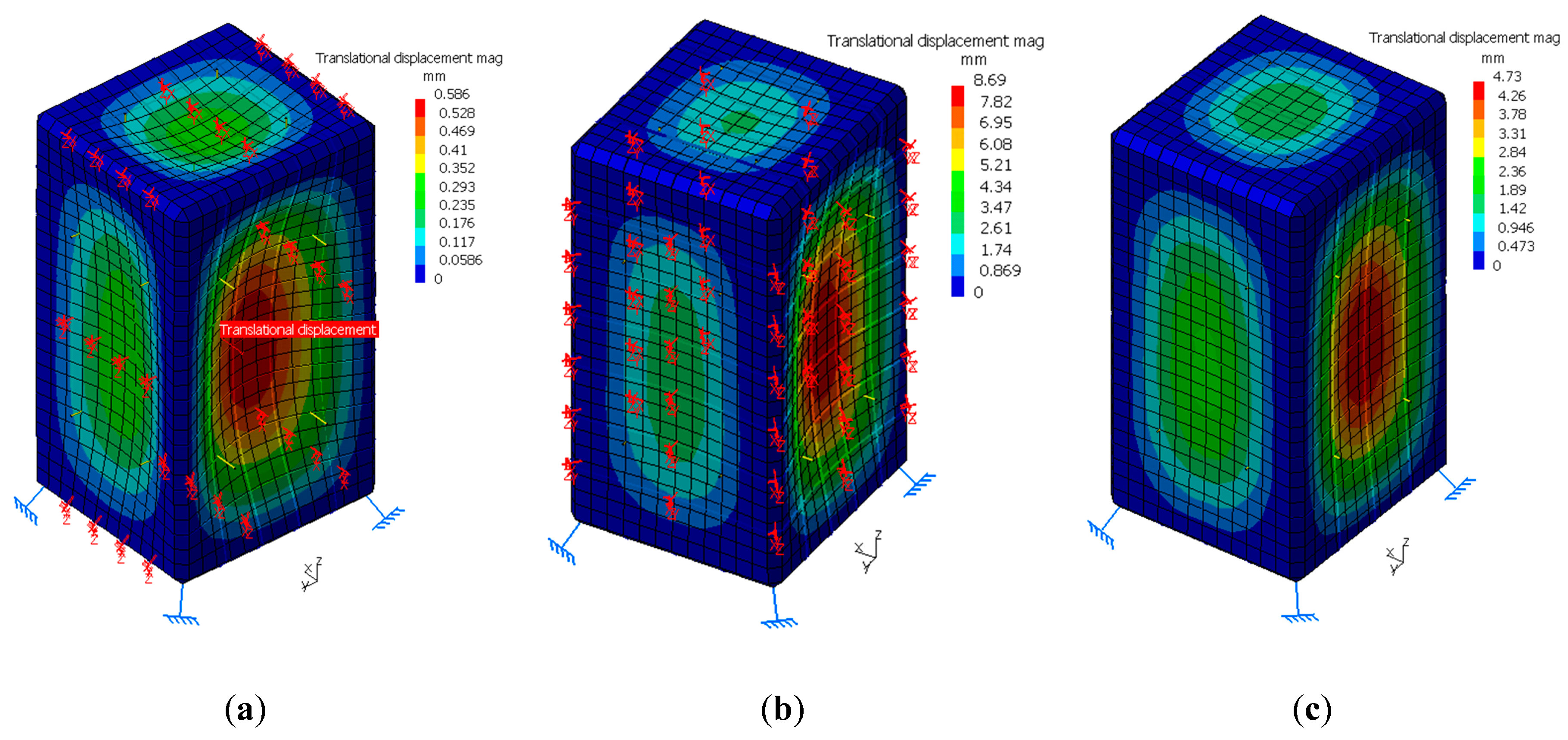
In the design stage, the von Misses stress was used as the criterion to determine the design points. The stress values for different cases are presented in Table 3, and the maximum thickness was selected for further analysis in this study. The results of buckling calculations for different compartments are reported in Table 4. The geometric parameters including length (a), width (b), and thickness (t) and the force are obtained in mm and Newton, respectively.
The results show that the maximum critical buckling value (MCB) for steel compartments occurred in sheet No. 2. Moreover, the MCB was obtained in sheets No. 6 and 2 for aluminum housing at a depth of 20 and 60 m, respectively. We conclude that the state with the maximum critical buckling value has a higher strength.

4.2. FE Results

The equivalent von Misses stress contour for various cases extracted from the FE simulation is shown in Figure 3. The results indicated that among the studied materials for compartments, the highest von Misses stress was created in the steel compartment. The highest intensity of tension was observed at the edges of the walls. This means that these areas are more sensitive and should be given more attention in the design stage.
The deflection of different structures is demonstrated in Figure 4. From this figure, it is clear that the maximum deflection was generated in the compartment made of aluminum and at a depth of 20 m. The strength of the structure decreased as deformation increased. Therefore, it can be said that the parts that have more deformation are more exposed to damage.
The results obtained from FE analysis, including critical stress and value of deformation, are summarized in Table 5.
The first three shape modes of the buckling phenomenon of different materials are shown in Figure 5. The results reveal that the shape mode is independent of material. Therefore, the type of buckling can be specified using the buckling mode shapes in the structure.
The buckling factor (BF) is the factor of safety against buckling or the ratio of the buckling loads to the applied loads. Table 6 illustrates the interpretation of possible BF values for different cases. From this Table, it is clear that the steel structure had a higher buckling strength than the aluminum structure. Moreover, for aluminum, the value of BF increased by increasing the immersion depth.

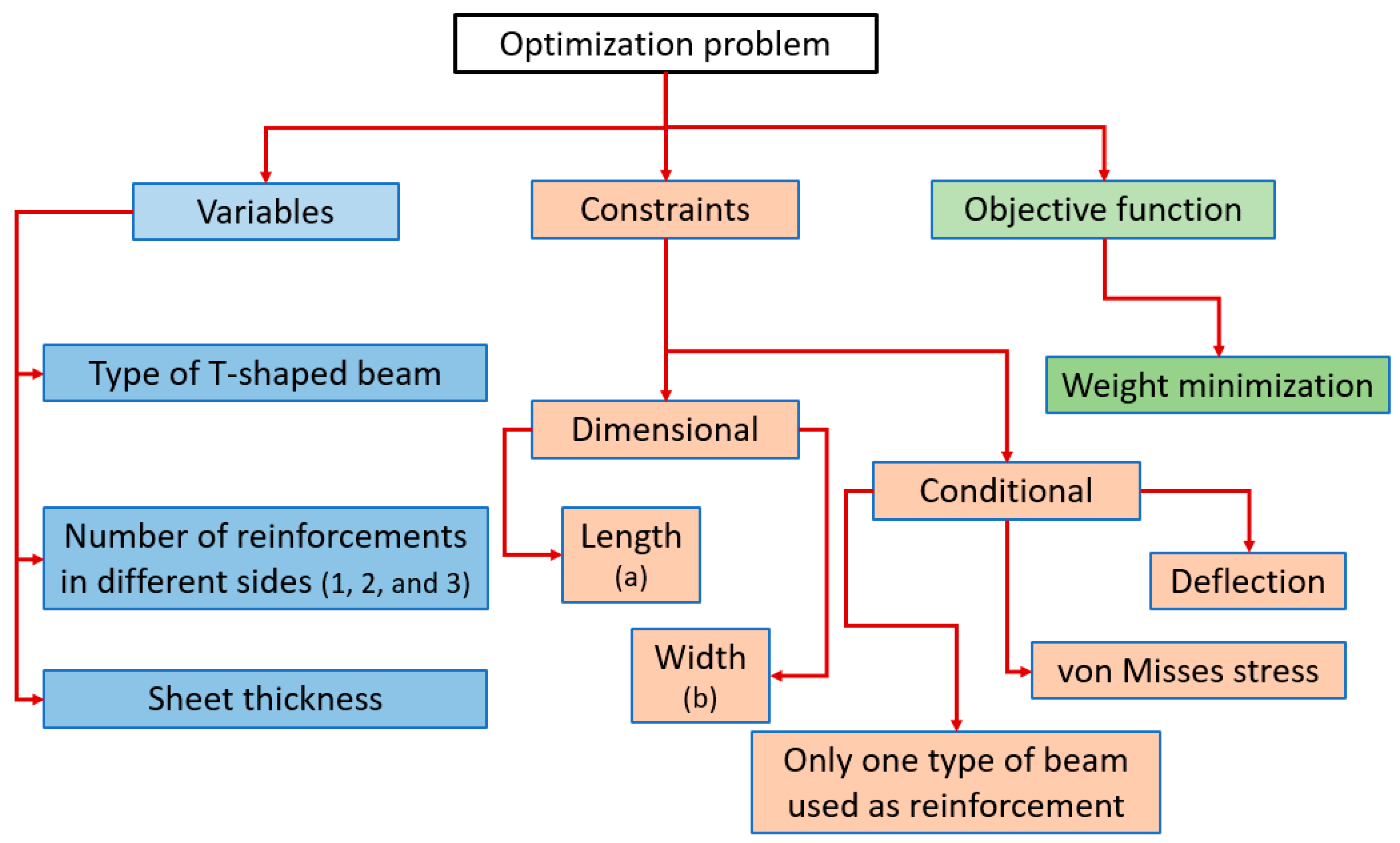
5. Optimization Process of the Structure Weight

Optimization is a mathematical discipline that concerns the finding of minima and maxima of functions subjected to different constraints. Various optimization techniques, including “linear programming” and so on, are used to solve problems in different industries. Today, optimization comprises a wide variety of techniques from Operations Research (OR), Artificial Intelligence (AI), and Computer Science (CS). In the present optimization problem, the weight of the compartment is considered as an objective function that should be minimized. The geometric dimensions of the compartment, including length (a) and width (b), are considered as constraints in the optimization problem. In other words, in the optimization process, the external dimensions of the compartments are constant. Moreover, optimization variables for all cases (steel, Al + Depth 20, and Al + Depth 60) include sheet thickness, number of reinforcements in each side, and type of reinforcements. One of the constraints in solving this problem is that only one type of T-shaped beam can be used at a time. In order to determine the type of T-shaped beam to be used, the standard sizes of the beams according to Figure 1 have been entered into the software to obtain a response and the correspondence of the sizes with the compartment dimensions. In addition, at each stage of the optimization, the values of von Misses stress and deflection of the compartment must be less than the allowable value at the design stage. In summary, this problem consists of five variables, two dimensional constraints, three conditional constraints, and an objective function, as shown in Figure 6.
This process was performed using FE software. The maximum and minimum values of the sheet thickness were 12 and 1 mm, respectively, with an interval of 1 mm. A range of 1–10 was also assumed for the number of reinforcement beams. The trial and error method for obtaining the minimum weight of the structure was used. All possible states in different combinations of variables were analyzed, and by comparing the responses, the most optimal state was found. Table 7 presents the optimal design parameters for each compartment. The results indicated that the steel compartment had the highest reliability, while the aluminum one had the lowest weight at a depth of 20 m. However, the aluminum compartment at a depth of 60 m had the lowest thickness.
Next, Figure 7 shows the stress contours of the optimal compartments. As seen in this figure, the maximum stress was created in the steel compartment, the aluminum compartment with a depth of 60 m, and the aluminum compartment with a depth of 20 m, respectively.

6. Conclusions

In the present study, a rectangular compartment made of different materials and sizes was analyzed using FEM and analytical methods. To validate the FE simulation, the FE results are compared to the results of the analytical solution. Then, to reduce the weight of the structure, design optimization was performed considering different variables such as thickness, etc. Our conclusion is that the analytical and simulation results for the design of the desired compartments are in good agreement, with a difference of less than 10%. In addition, the final optimized design of the compartment was reported based on the least possible weight. The important achievements of this research are as follows:
  • Within the prevailing conditions, the best compartments were designed. The weight of the compartment was reduced by utilizing reinforced conductors while respecting the design principles and considering the minimum thickness.
  • The stress results calculated using the analytical method are in good agreement with the results of finite element analysis.
  • The final thicknesses computed against the load and local buckling had good and adequate strength. It seems that they can be used at arbitrary depths.
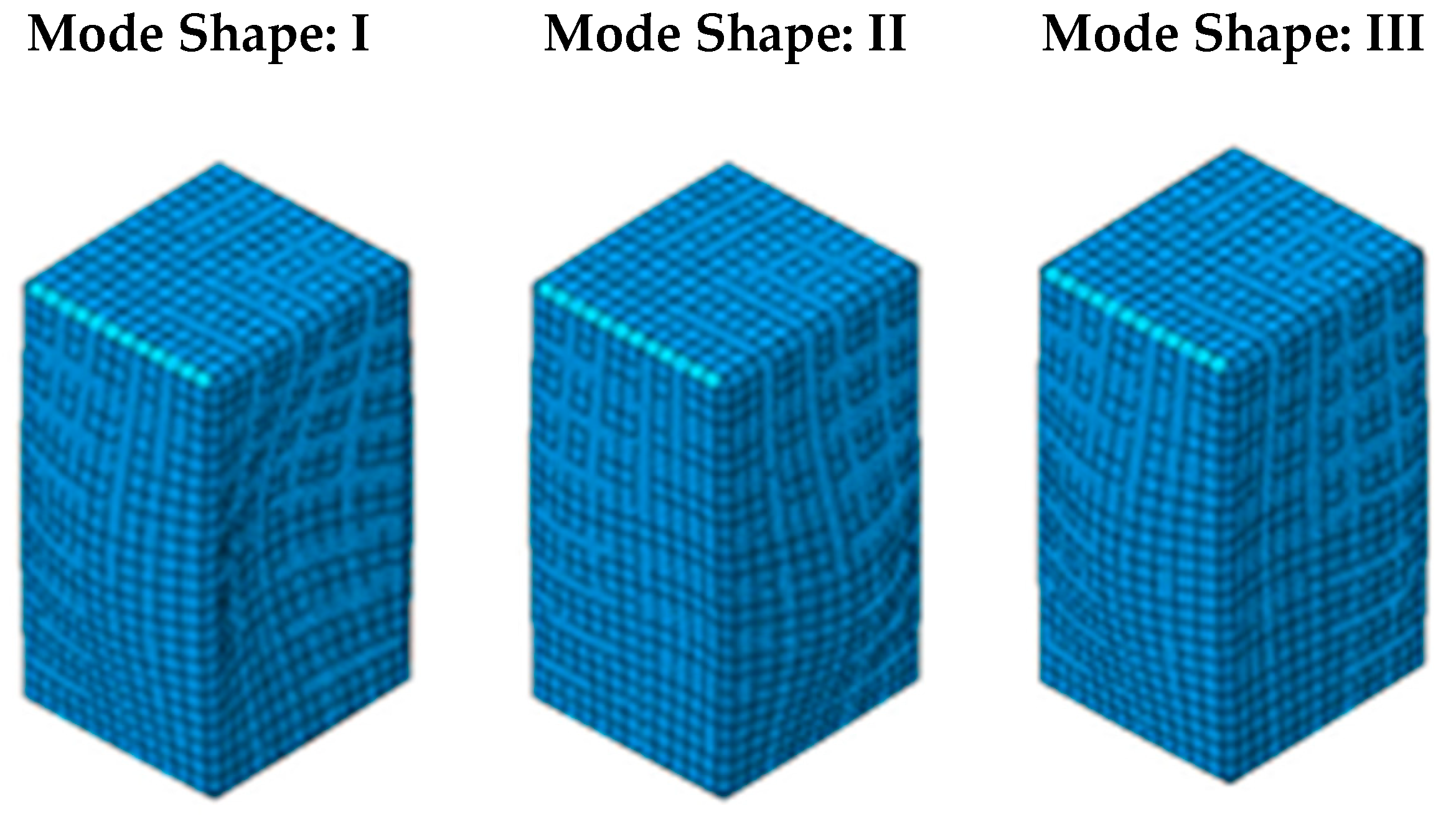
  • The buckling shape mode is independent of material and can be used to classify the type of the buckling phenomenon.
  • The finite element results reveal that the maximum stress occurs at the edge of the walls, so the most critical area in such structures is the edge of the outer wall or the corners.

Author Contributions

Conceptualization, M.O.B., and K.R.K.; Data curation, M.O.B., and K.R.K.; Formal analysis, M.O.B., K.R.K., S.S.R.K., M.P., and N.A.; Funding acquisition, S.S.R.K., and M.P.; Investigation, M.O.B., K.R.K., S.S.R.K., M.P., and N.A.; Methodology, M.O.B., and K.R.K.; Project administration, M.O.B., K.R.K., S.S.R.K., and M.P.; Resources, S.S.R.K., and M.P.; Software, M.O.B., K.R.K., and S.S.R.K.; Supervision, M.O.B., K.R.K., and S.S.R.K.; Validation, M.O.B., K.R.K., S.S.R.K., M.P., and N.A.; Visualization, M.O.B., K.R.K., S.S.R.K., M.P., and N.A.; Writing—original draft, M.O.B., K.R.K., and N.A.; Writing—review & editing, M.O.B., K.R.K., and S.S.R.K. All authors have read and agreed to the published version of the manuscript.

Funding

The research was supported by the Ministry of Education, Youth, and Sports of the Czech Republic and the European Union (European Structural and Investment Funds Operational Program Research, Development, and Education) in the framework of the project “Modular platform for autonomous chassis of specialized electric vehicles for freight and equipment transportation”, Reg. No. CZ.02.1.01/0.0/0.0/16_025/0007293, as well as the financial support from internal grants in the Institute for Nanomaterials, Advanced Technologies and Innovations (CXI), Technical University of Liberec (TUL).

Conflicts of Interest

We declare that this manuscript has no competing interests.

References

  1. Nouri, M.; Ashenai-Ghasemi, F.; Rahimi-Sherbaf, G.; Kashyzadeh, K.R. Experimental and Numerical Study of the Static Performance of a Hoop-Wrapped CNG Composite Cylinder Considering Its Variable Wall Thickness and Polymer Liner. Mech. Compos. Mater. 2020, 56, 339–352. [Google Scholar] [CrossRef]
  2. Walker, A.C. A brief review of plate buckling research. In The Behavior of Thin-Walled Structures; Elsevier: London, UK, 1984. [Google Scholar]
  3. Bijlaard, P.P.; Fisher, G.P. Interaction of Column and Local Buckling in Compression Members; NACA Technical Note 2640; National Advisory Committee for Aeronautics: Moffett Field, CA, USA, 1952.
  4. Bijlaard, P.P.; Fisher, G.P. Column Strength of H Sections and Square Tubes in the Postbuckling Range of the Component Plates; NACA Technical Note 2994; National Advisory Committee for Aeronautics: Moffett Field, CA, USA, 1953.
  5. Bresler, B. Design criteria for reinforced columns under axialload and biaxial bending. ACI J. Proc. 1960, 57, 481–490. [Google Scholar]
  6. Horowitz, B. Design of columns subjected to Biaxial bending. ACI Struct. J. 1989, 86, 717–722. [Google Scholar]
  7. Rafiq, M.Y. Genetic Algorithms in Optimum Design, Capacity Check and Final Detailing of Reinforced Concrete Columns. Trans. Built Environ. 1995, 13, 161–169. [Google Scholar]
  8. Cedolin, L.; Cusatis, G.; Eccheli, S.; Roveda, M. Biaxial bending of concrete columns: An analytical solution. Stud. Res. 2006, 26, 1–28. [Google Scholar]
  9. Yang, P.; Liu, H.; Huang, Z. A Comparison of seismic behavior between Specially Shaped Column frame structure and Rectangular Column frame structures. In Proceedings of the 14th World Conference on Earthquake Engineering, Beijing, China, 12–17 October 2008. [Google Scholar]
  10. Chen, Z.H.; Rong, B.; Fafitis, A. Axial compression stability of a crisscross section column Composed of concrete-filled square steel tubes. J. Mech. Mater. Struct. 2009, 4, 1787–1799. [Google Scholar] [CrossRef]
  11. Rodrigues, H.; Arêde, A.; Varum, H.; Costa, A.G. Experimental evaluation of rectangular reinforced concrete column behavior under biaxial cyclic loading. Earthq. Eng. Struct. Dyn. 2013, 42, 239–259. [Google Scholar] [CrossRef]
  12. Avcar, M. Elastic buckling of steel columns under axial compression. Am. J. Civ. Eng. 2014, 2, 102–108. [Google Scholar] [CrossRef]
  13. Gumble, A.N.; Pajgade, P.S. Comparison between specially shaped columns and rectangular columns in R.C. structure. Int. J. Adv. Eng. Res. Dev. 2015, 2, 679–684. [Google Scholar]
  14. Kervalishvili, A.; Talvik, L. Modified procedure for buckling of steel columns at elevated temperatures. J. Constr. Steel Res. 2016, 127, 108–119. [Google Scholar] [CrossRef]
  15. Dahiya, N.; Sehgal, V.K.; Saini, B. Analysis and Design of Rectangular and L-Shaped Columns Subjected to Axial Load and Biaxial Bending. Int. J. Struct. Eng. Anal. 2016, 2, 15–22. [Google Scholar]
  16. Mohammad, F.A.; Seyan, D.A. Optimum Design of Reinforced Concrete Rectangular Columns Subjected to Axial Compression and Biaxial Bending Moments. Athens J. Technol. Eng. 2016, 3, 225–239. [Google Scholar] [CrossRef]
  17. Munhoz, F.S.; Giongo, J.S. Variation analysis effects of square and rectangular columns section with different longitudinal reinforcement rates in the main reinforcement two pile caps analysis. IBRACON Struct. Mater. J. 2017, 10, 760–787. [Google Scholar] [CrossRef] [Green Version]
  18. Jiang, J.; Zhang, J.; Liu, J.; Chiew, S.; Lee, C. Effect of welding and heat treatment on strength of high-strength steel columns. J. Constr. Steel Res. 2018, 151, 238–252. [Google Scholar] [CrossRef]
  19. Kandpal, U. Comparative Analysis of Rectangular and Square Column for Axial loading, Uniaxial & Biaxial Bending. Int. Res. J. Eng. Technol. 2018, 5, 465–468. [Google Scholar]
  20. Rasmussen, K.J.R.; Hancock, G.J. Tests of high strength steel columns. J. Constr. Steel Res. 1995, 34, 27–52. [Google Scholar] [CrossRef]
  21. Schuman, L.; Back, G. Strength of Rectangular Flat Plates under Edge Compression; NACA Report No.356; National Advisory Committee for Aeronautics: Moffett Field, CA, USA, 1930.
  22. Karman, T.; Sechler, E.E.; Donnel, L.H. The strength of thin plates in compression. Trans. ASME 1932, 54, 53–57. [Google Scholar]
  23. Patil, S.R.; Murthy, H.N.; Srivatsa, G.S.; Yandigeri, V.S.; Meti, B.; Angadi, G.; Harish, D.V.N. Study of Vibration Behaviour of Stiffened Polymer Composite Shells for Underwater Structural Applications. Def. Sci. J. 2020, 70, 342–350. [Google Scholar] [CrossRef]
  24. Chu, Y.L.; Wang, C.M.; Park, J.C.; Lader, P.F. Review of cage and containment tank designs for offshore fish farming. Aquaculture 2020, 519, 734928. [Google Scholar] [CrossRef]
  25. Strand, I.M.; Faltinsen, O.M. Linear wave-induced dynamic structural stress analysis of a 2D semi-flexible closed fish cage. J. Fluids Struct. 2020, 94, 102909. [Google Scholar] [CrossRef]
  26. Graves Smith, T.R. The ultimate strength of locally buckled columns of arbitrary length. In The Thin-Walled Steel Constructions; Crosby-Lockwood: London, UK, 1967. [Google Scholar]
  27. Bringas, J.E. Handbook of Comparative World Steel Standards, 3rd ed.; ASTM International: West Conshohocken, PA, USA, 2004. [Google Scholar]
  28. Koloor, S.S.R.; Abdullah, M.A.; Tamin, M.N.; Ayatollahi, M.R. Fatigue damage of cohesive interfaces in fiber-reinforced polymer composite laminates. Compos. Sci. Technol. 2019, 183, 107779. [Google Scholar] [CrossRef]
  29. Karimzadeh, A.; Koloor, S.S.R.; Ayatollahi, M.R.; Bushroa, A.R.; Yahya, M.Y. Assessment of nano-indentation method in mechanical characterization of heterogeneous nanocomposite materials using experimental and computational approaches. Sci. Rep. 2019, 9, 15763. [Google Scholar] [CrossRef] [PubMed] [Green Version]
  30. Mohamady, S.; Montazeri, A.; Ahmad, R.R. Modeling of sound-structure interaction in a rectangular enclosure using finite element method. IEEE Symp. Ind. Electron. Appl. 2009, 2, 748–753. [Google Scholar]
  31. Reza Kashyzadeh, K.; Farrahi, G.H.; Shariyat, M.; Ahmadian, M.T. Experimental and finite element studies on free vibration of automotive steering knuckle. Int. J. Eng. Trans. B Appl. 2017, 30, 1776–1783. [Google Scholar]
  32. Reza kashyzadeh, K. Effects of axial and multiaxial variable amplitude loading conditions on the fatigue life assessment of automotive steering knuckle. J. Fail. Anal. Prev. 2020, 20, 455–463. [Google Scholar] [CrossRef]
  33. Reza Kashyzadeh, K. A new algorithm for fatigue life assessment of automotive safety components based on the probabilistic approach: The case of the steering knuckle. Eng. Sci. Technol. Int. J. 2020, 32, 392–404. [Google Scholar] [CrossRef]
  34. Flugge, W. Stresses in Shells; Julius Springer: Berlin, Germany, 1960. [Google Scholar]
  35. Timoshenko, S.; Woinowsky-Krieger, S. Theory of Plates and Shells; McGraw–Hill Publishing Co., Inc.: New York, NY, USA, 1960. [Google Scholar]
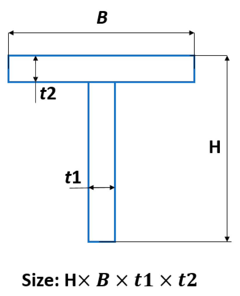
Figure 1. Specifications of the cross-section of the T-shaped beam. B: flange width, H: height of section, t1: web width, t2: slab thickness.
Applsci 10 08449 g001
Figure 2. Final structures of reinforced compartments with T-shaped beams: (a) steel compartment, (b) aluminum compartment (depth of 20 m), and (c) aluminum compartment (depth of 60 m).
Applsci 10 08449 g002
Figure 3. Contours of von Misses stress for various compartments: (a) steel compartment, (b) aluminum compartment (depth of 20 m), and (c) aluminum compartment (depth of 60 m).
Applsci 10 08449 g003
Figure 4. Deflection contours as FE results for various cases of compartments: (a) steel compartment, (b) aluminum compartment (depth of 20 m), and (c) aluminum compartment (depth of 60 m).
Applsci 10 08449 g004
Figure 5. The first three mode shapes of buckling of compartment.
Applsci 10 08449 g005
Figure 6. Details of the optimization process.
Applsci 10 08449 g006
Figure 7. The results of stress analysis of the optimized compartments made of different materials including (a) steel compartment, (b) aluminum compartment (depth of 20 m), and (c) aluminum compartment (depth of 60 m).
Applsci 10 08449 g007
Table 1. Specifications of T-shaped reinforcements for different materials of the compartment.
MaterialNumber of T-Shaped BeamsCross-Section Dimensions (mm)Side of Reinforcements
Steel450 × 50 × 5 × 51
450 × 50 × 5 × 52
750 × 50 × 5 × 53
Aluminum
(depth of 20 m)
380 × 80 × 9 × 91
380 × 80 × 9 × 92
480 × 80 × 9 × 93
Aluminum
(depth of 60 m)
380 × 80 × 9 × 91
380 × 80 × 9 × 92
680 × 80 × 9 × 93
Table 2. Geometrical and mechanical properties of the rectangular compartment [27].
External Dimensions (mm)
Length × Width × Height
Internal Dimensions (mm)
Length × Width × Height
Poisson RatioYoung’s Modulus (GPa) σ y (MPa)Safety FactorDepth (m)Body Material
828 × 898 × 1551768 × 838 × 14930.2662104002.760St60
0.34672.7288420Al5083H321
0.34672.7288460Al5083H321
Table 3. Characteristics of compartments made of different materials.
MaterialsGeometric Parameters of the SheetStress ComponentsVon Misses StressW(x, y)
abt σ x σ y τ x y
Steel798152236170.5276.160148.152.3
868152237.8171.4783.980148.373
79886827.7156.39139.450148.571.1
Aluminum (depth of 20 m)79815223082.8942.78071.783.5
868152231.782.9946.07072.054.6
79886823.774.9568.36071.931.7
Aluminum (depth of 60 m)798152251.983.1642.69072.022
868152254.982.9546.12072.002.7
7988684174.9668.41071.981
Table 4. Buckling results obtained using the analytical solution.
MaterialCritical Value of NnmabtNo. Sheet
Steel3.01 × 10711798868381
7.16 × 10721798868382
1.8 × 107118681522383
3.2 × 107218681522384
2 × 107117981522385
3.4 × 107217981522386
Aluminum (depth of 20 m)6.5 × 10611798868321
1.5 × 10721798868322
3.9 × 106118681522323
6.8 × 106218681522324
4.5 × 106117981522325
7.3 × 106217981522326
Aluminum (depth of 60 m)3.2 × 10711798868551
7.7 × 10721798868552
1.9 × 107118681522553
3.4 × 107218681522554
3.2 × 107117981522555
3.7 × 107217981522556
Table 5. Critical stress and deformation extracted from FE software.
Compartment TypeMaximum Deformation (mm)Critical Stress (Mpa)Safety Factor
St 600.5862413
Al + depth 208.691172.4
Al + depth 604.731882
Table 6. Buckling factor for different cases of compartments.
Mode No.BF
SteelAl + Depth 20Al + Depth 60
1179.9912.25923.474
Table 7. Details of optimum design for different cases of compartments.
Compartment TypeType of Reinforced BeamNumber of BeamsSheet Thickness (mm)Safety FactorWeight (kg)
Steel50 T4, 4, 71031199
Al + Depth 2040 × 80 × 7 T3, 3, 4122.83305
Al + Depth 6080 × 80 × 9 T3, 3, 683.51446
Publisher’s Note: MDPI stays neutral with regard to jurisdictional claims in published maps and institutional affiliations.

