1. Introduction
Cracks in concrete structures is some of the most important indications (or predictors) for significant structural distress or damage caused by various causes such as aging. If the crack is reliably inspected, severe damage (or possible failure) to concrete facilities can be effectively forestalled, and the life of the facilities can be lengthened through appropriate maintenance. Conventional crack inspections are performed by trained inspectors who visually detect cracks and then measure their length and width using suitable measuring tools (crack rulers, crack microscopes, etc.). Although human-based inspection may be effective, the objectivity and reliability of the records for the cracks may easily be reduced because inspection relies on the subjectivity of the inspector. In addition, it is difficult to determine the progress of damage if the inspector changes. Thus, these drawbacks have led to extensive research on crack inspection that secures objectivity and accuracy while enabling the convenience of recording and storing data.
Over the past few decades, image processing (IP)-based crack inspection techniques have been widely studied. This processing refers to the entire computational process of the photograph of a concrete structure; image input/output, digitization, segmentation, defect management, and defect detection. Thus, it not only detects cracks but also measures the width and orientation of the recognized cracks. IP-based methods generally determine whether or not an image pixel is part of a crack region by using predefined gradient filters and a binary classifier. Oliveira and Correia showed that it is possible to detect crack by distinguishing darker areas [
1,
2]. Many researchers proposed effective crack detection that enhances cracks using noise filtering on the images [
3,
4]. Moreover, various image processing techniques for crack inspection have also been studied based on morphology [
5,
6,
7], fuzzy [
8,
9], and percolation [
10,
11] techniques. However, the accuracy of these rule-based image processing is variant to the focal length of the image, the influence of the shooting environment (illuminance, intensity, etc.), shooting quality, and the resolution. This weakness requires new filter modeling every time depending on the input image for accurate detection.
To improve the rule-based crack inspection methods, machine learning (ML) has attracted attention from researchers. Machine learning refers to computer algorithms learning important patterns or rules by itself based on given data without being explicitly programmed. ML-based crack inspection methods are categorized into two main groups as artificial neural networks (ANN) use or without ANN use. Conventional ML-based crack inspection methods [
12,
13,
14,
15,
16] first extract crack features using image processing, then evaluate whether or not the extracted features indicate cracks without ANN use. Many researchers have used various ML algorithms for crack detection, including Support Vector Machine [
12,
13], Bayesian [
14], genetic algorithm [
15], and decision trees [
16]. However, conventional ML-based methods have limitations as their accuracy inevitably relies on the extracted crack features by image processing.
Recently, as another category, ANN-based crack detection techniques are actively being researched. As one of the machine learning techniques, ANN learns given data inspired by biological neural networks. Particularly, deep ANN (i.e., deep learning) [
17] is acclaimed with outstanding performance. Previous studies have shown that the ANN-based method can contribute to overcoming the difficult or infeasible problems of the IP-based methods. For example, Xu et al. [
18] showed that the ANN using a restricted Boltzmann machine can successfully detect a crack in spite of the limited training samples. Zhang et al. [
19] demonstrated that the crack in a road image can be determined with an accuracy of 87% using the convolutional neural network (CNN) consisting of only four layers. More recently, Chen et al. [
20] and Li et al. [
21] proposed improved CNNs that extract crack patches in an image with 99% accuracy. Based on these successes, studies have been performed on methods to inspect and analyze the appearance of aging large-scale infrastructure based on artificial neural networks using Unmanned Aerial Vehicles (UAV) such as drones equipped with imaging equipment [
22,
23]. It is obvious that the aforementioned ANN-based studies showed sufficient potential for crack detection. However, they are still in the early stage of development and require further in-depth studies. Moreover, to the best of our knowledge, only a few studies [
24,
25] have pertained to measuring methods for the collection essential information (length and width) for crack inspection from the ANN detection results.
This study aims to propose a framework that can inspect crack for concrete ground structures with high accuracy, speed, and convenience. For this purpose, this paper proposes not only:
- (1)
ANN-based crack classification and segmentation methods, but also
- (2)
an IP-based crack analysis method, and investigates
- (3)
the feasibility of the proposed methods through verification.
The remainder of this paper is organized as follows:
Section 2 introduces the crack detection and measurement method.
Section 3 interprets the verification method and identification result.
Section 4 is the discussion of the results.
2. Materials and Methods
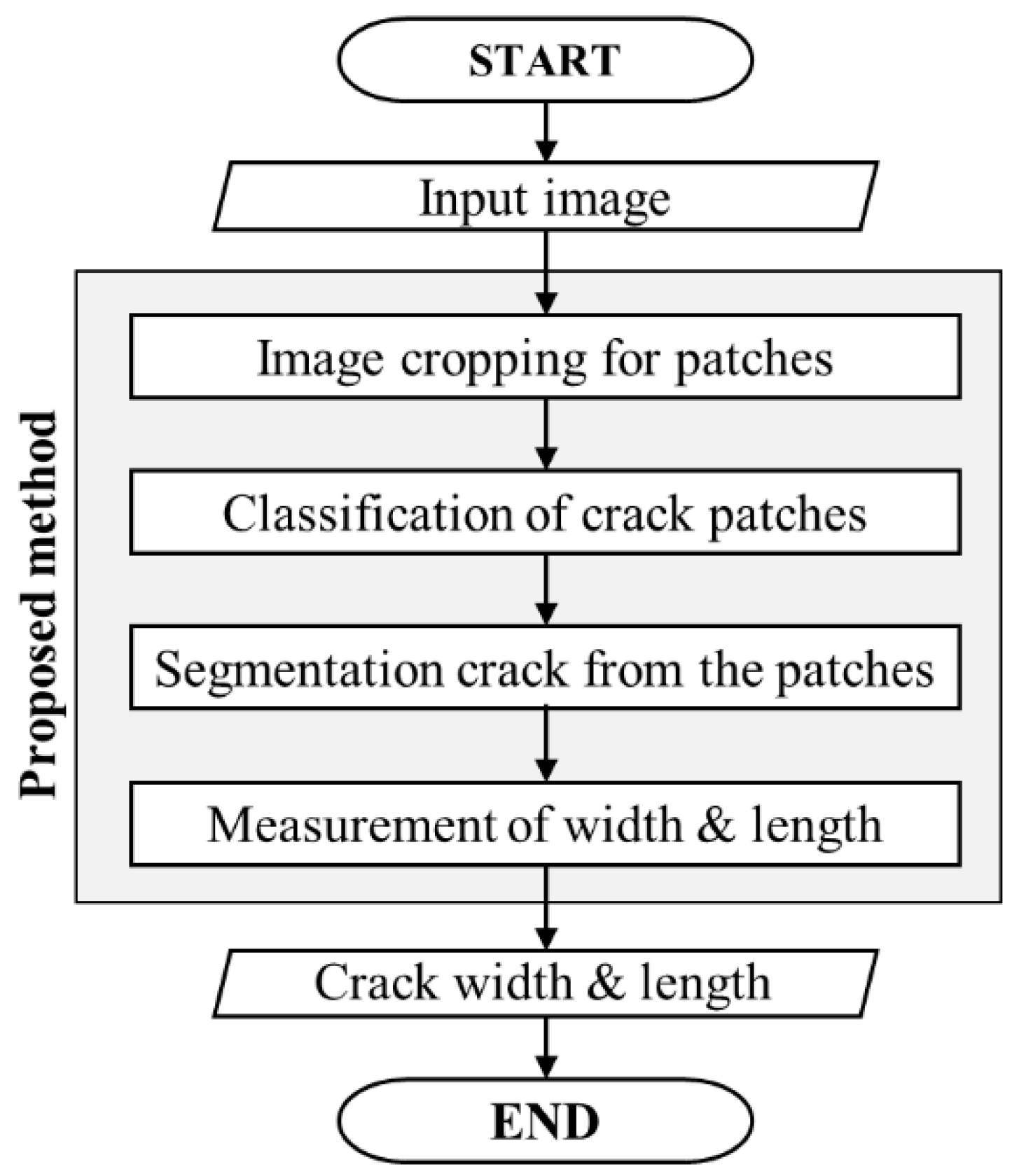
The overall framework proposed in this article includes four processing phases:
- (1)
cropping the input image to patches
- (2)
classification of concrete crack patches
- (3)
segmentation of concrete crack
- (4)
measurement of crack characteristics.
Figure 1 summarizes the workflow of this four-phase framework.
2.1. Cropping Input Image
This step aims to the input high-resolution image into multiple patches. For this purpose, the image cropping technique is used. Regardless of the resolution of the input image, this task divides the image into patches of 227 × 227 pixels size. The patches are used as the input image for the second and third phases. This task is essential to efficient and quick crack inspection by reducing computation cost.
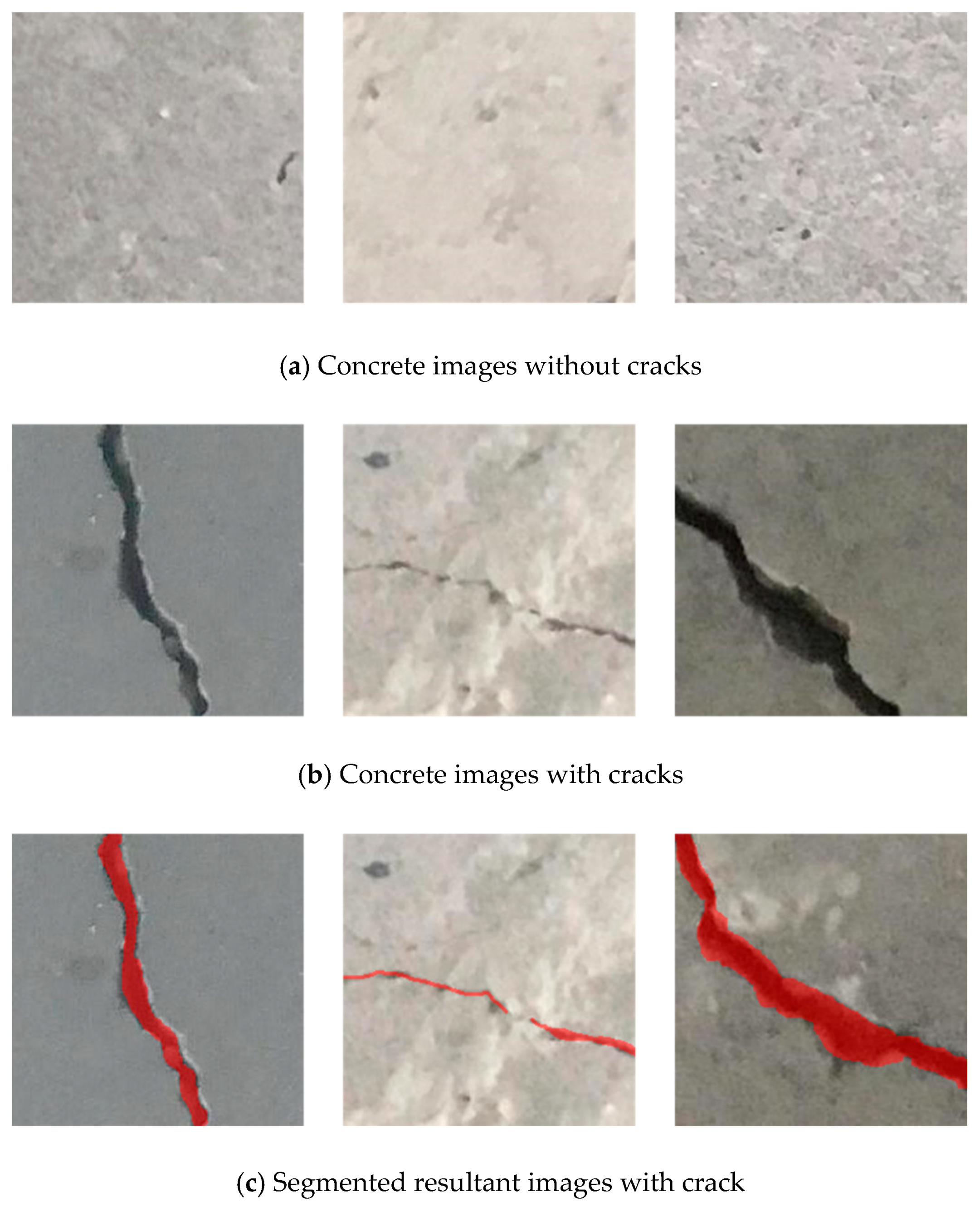
2.2. Classification of Concrete Crack Patches Based on Neural Network
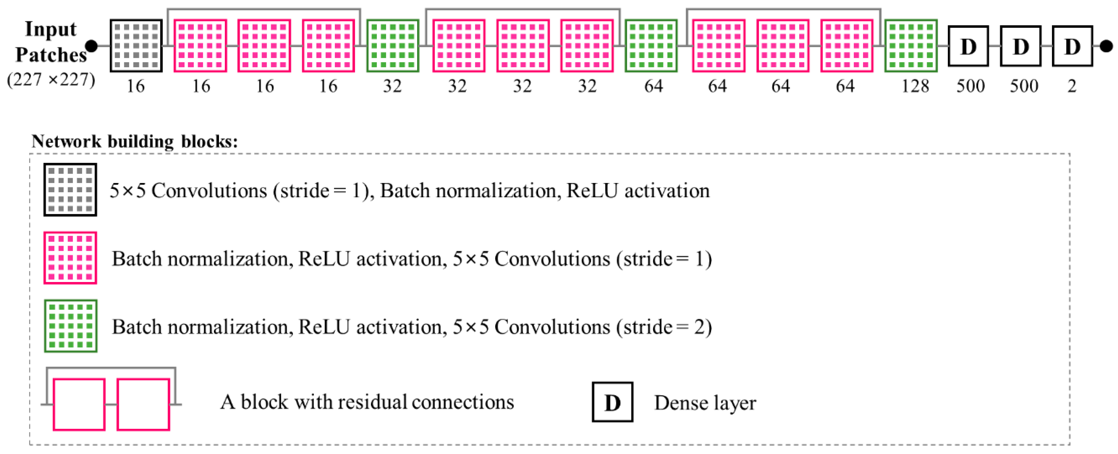
The goal of this step is to classify only the patches that contain cracks among the patches constituting the input image. For the purpose, this study proposed a convolution-based crack classification neural network (i.e., CNN) based on the previous study [
26]. As shown in
Figure 2, the network architecture is designed to reduce the dimensions of the images using stride and pooling then finally to determine whether cracks are included using dense networks. Therefore, the number of output classes is two. The input size of the network set to 227 × 227 for efficient classification and network training. Although the input size is can be enlarged, an increment of the size will make network learning difficult and include more background in the output.
The proposed network consists of 12 layers of convolutions. The number of convolution filters at layers is designed to 16, 32, 64, and 128, where the filter size is the same as 5 × 5. Note that the more convolutional filters the network contains, the higher possibility that image features and unseen patterns get captured. The convolution filters generate the integral of the pixel-wise multiplication of input patch and convolutional kernel, as follow:
where
yij and
xij are the pixel values at (
i,
j) of output and input.
k is the convolutional kernel, which is always square.
w and
b are the elements of weights and biases, which are determined by training. s is the stride size corresponding to the convolutional kernel shift at each step (in this study, 1 or 2).
In order to prevent information loss due to pooling, stride convolution is performed only once after convolution filter group operation, instead of pooling for every convolution filter. Zero-padding is always applied to input images. Note that pooling extracts useful values from the filtered image, but does not consider the remaining values that may be useful in other filters. This study also applied a residual network to prevent the gradient vanishing problem during backpropagation. Rectified linear unit (ReLU) is used as an activation function determining the output of a neural network to simplify the computation and facilitate the training process. Finally, this study configured the network to improve performance by adjusting the order of convolution, batch normalization, and activation to maximize batch normalization and performance as shown in
Figure 2.
2.3. Segmentation of Concrete Crack Based on Neural Network
This study developed a crack segmentation neural network based on the presented method (i.e., HiRes3DNet) in the previous study [
27] which is mainly used for medical image segmentation. As shown in
Figure 3, the develop network consists of 10 layers of convolutions and a dense layer. The number of convolution filters at layers is designed to 16, 32, and 64 where the filter size is the same as 5 × 5. Stride size for convolution was set to 1. The input size of this network set to 227 × 227 which is the same as the classification network. The proposed network assigns a value of 1 or 0 as the output whether each pixel in the input patch corresponds to a crack. As mentioned above, the network also includes batch normalization, residual neural network, zero-padding. ReLU is also used as an activation function.
2.4. Measurement of Crack Characteristics Based on Image Processing
This study used the image processing methods to measure the crack characteristics of the cracks in the images partitioned through the neural networks. This process comprises three steps: thinning, tracking, measurement. Thinning and tracking algorithms are used as preprocessing prior to measurement of crack length and width.
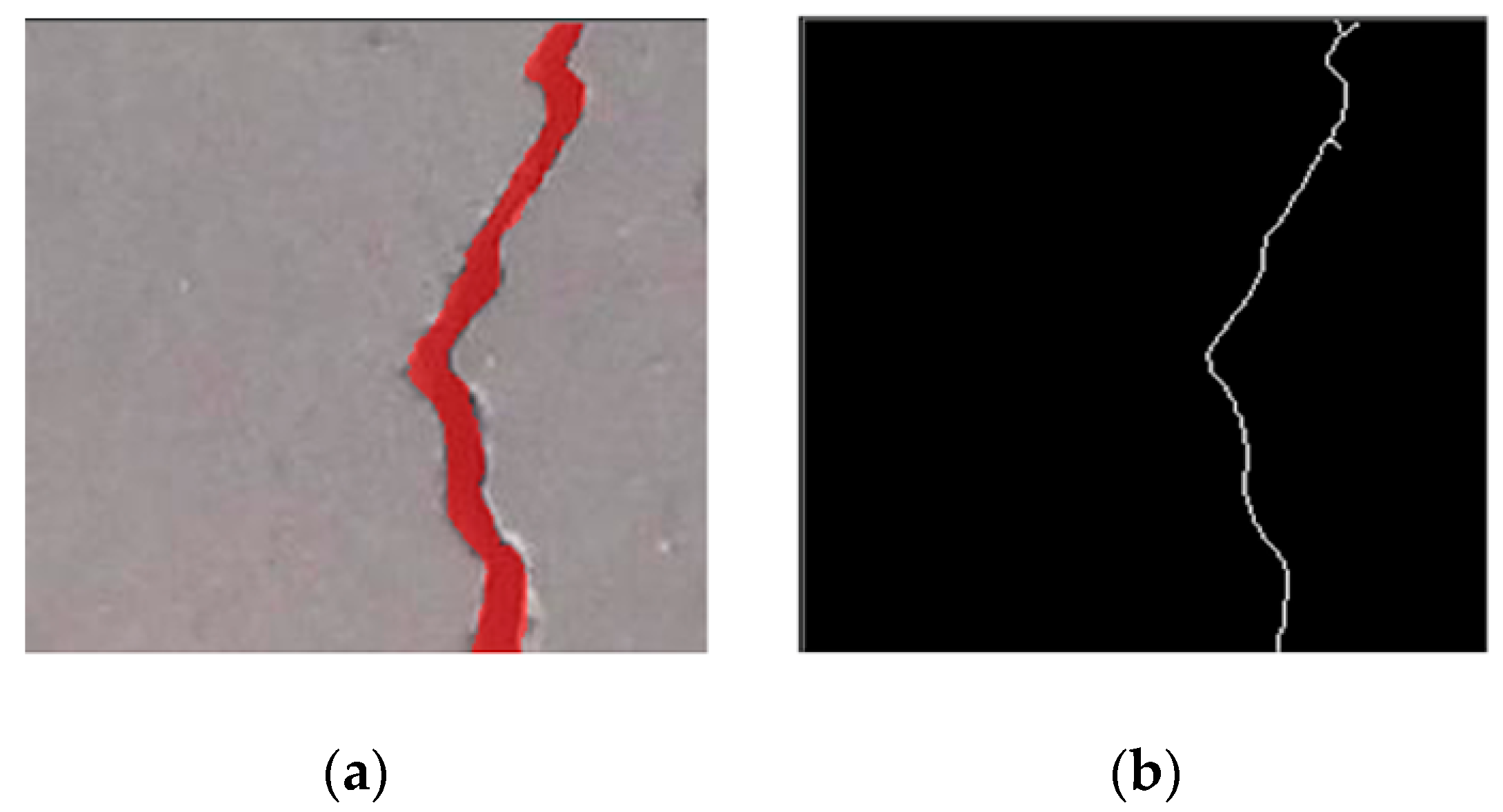
First, a thresholding step for the segmented crack image is conducted by using Otsu’s method [
28]. This task helps to control the noise and enhance the crack area in the image. Then the processed image is thinned by using a Voronoi thinning algorithm. This algorithm plays a role in gradually peeling off the lateral surface of the crack area by dividing the plane into minimum distances to a specific point. As shown in
Figure 4, the segmented crack image is resultingly converted into 1-pixel wide lines image that is a binary image composing of 1 or 0 value. Note that there is no information in the thinned image about sorted pixels that connect the start and endpoints yet.
Secondly, a tracking algorithm called also a region-growing is implemented to sort the thinned lines. For that, a pixel of which value is 1 is arbitrarily selected in the thinned image as a starting point for tracking. Then tracking algorithm identifies adjacent pixels that are homogeneous pixels or not and expanding the area by collecting pixels with the same data value. Note that the identification is performed in 8 directions in this study; up, down, left, right, upper left upper right, lower left, and lower right (
Figure 5). The final output of the tracking algorithm is a sequenced crack pixel coordinate dataset.
Lastly, the crack characteristics, length and width, are calculated. The result of the tracking algorithm is the form of a 1 pixel-wide free-form spline. For measuring the length of the crack, the lengths of the pixels in the spline are summed. Note that the length changes depending on the distribution pattern of pixels. For example, if two pixels are located side by side in the horizontal or vertical direction, the length is easily calculated by gathering the horizontal or vertical size of the pixel. On the other hand, if two pixels are distributed in the diagonal direction, the length is calculated by the Pythagorean theorem. Thus, the length of the crack length is measured by sequentially considering the distribution direction every two pair-pixels. Eventually, the crack length of the input image obtained through the summation of lengths calculated in every crack patch.
Crack width is obtained by profiling algorithm (
Figure 6). This algorithm is based on the that the length (or longitudinal) direction and width (or transverse) direction are perpendiculars. For using the fact, the algorithm firstly converts the spline line of the previous tracking to a number of points then determines the length direction of each point by using its back and forth points. Note that the spline data has longitudinal directionality because it has the sorted pixel sequence. Subsequently, the profiling algorithm determines the width directions of the points by verticalizing the length directions. At each point, the width is calculated toward its width direction until there is no crack pixel in the thresholded image thereafter. Finally, the profiling algorithm determines crack width by averaging the calculated width at every point in input patches.
4. Discussion
Crack inspection is implemented by two consecutive processes: crack detection and measurement. This technique is very important in civil engineering because it is directly related to the safety, durability, and the applicability of concrete structures. Based on this fact, various automatic crack inspection methods have been proposed based on image processing (IP), machine learning (ML) algorithms, and artificial neural networks (ANN). In an objective and efficient manner, these crack inspections showed better performance than the conventional human-based method that relies on the subjectivity of inspectors. Particularly, ANN-based methods were outstanding in crack detection [
18,
19,
20,
21,
22,
23,
24,
25]. However, these approaches have rarely been considered in crack measurement [
18,
19,
20,
21,
22,
23]. This paper proposed a new framework that can inspect cracks objectively and efficiently in concrete ground structures through crack detection and measurement. The framework detects crack using artificial neural networks that classify crack patches in the input image and segment cracks in the classified patches. Subsequently, it analyzes crack characteristics (i.e., length and width) using image processing techniques. Verification using test data demonstrated that this proposed framework can reliably provide crack characteristics through the consecutive processes.
Convolutional neural network (CNN)-based crack classification is proposed in this study. Each layer has a number of convolution filters of different sizes. The convolution filter in the neural networks allows the conversion of an input image into an image that highlights the sought-after characteristics. Specifically, a learned convolution filter can play a role as a Sobel filter [
31] that detects edges then creates an image emphasizing the edges. The study consisted of a number of convolution filters of 5 × 5 size in each layer from 16 to 128 to build efficient crack classification. In the verification, the framework showed high classification accuracy of about 99%. Moreover, this high accuracy is in very good agreement with state-of-art techniques that use the same training data [
20,
21,
25]. These facts demonstrated that the filters in the proposed method were appropriate designed and used for properly classifying crack patches in the input image.
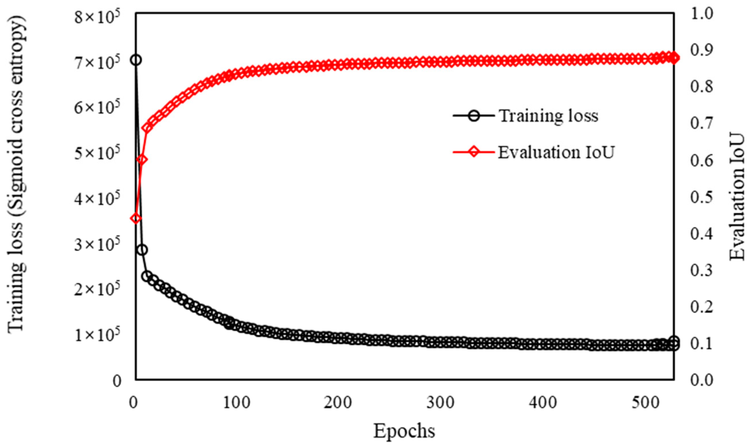
This study proposed a patchwise-crack detection method that divides an input image into patch units, then determines the presence of cracks in each patch by the classifier, and segments crack from the classified patches thereafter. It should be noted that this approach can overcome the lack of training data by obtaining multiple image patches from a single image, prevent the decline of architecture performance for high-resolution images, and overcome the imbalanced dataset problems by using only image patches with cracks. For example, the learning process for a segmentation neural network requires at least 1000 training data points that are not only crack images but also crack-labeled images. However, it is exceedingly difficult to manually label cracks in the obtained images from cameras (typically, 2960 × 1440 QHD resolution). Since the pixels of crack images may account for less than 1% of the pixels of the entire images, the learning performance can decline significantly due to imbalanced datasets. Based on these facts, this study implemented a patchwise-segmentation neural network and showed that the network has a reasonably high intersection over union (IOU) of 0.87 despite the limited number of 1751 learning data points. This result demonstrates the considerable potential of the proposed method.
The proposed method also has another advantage in that it can be applied not only to fixed-sized but also varied-sized images obtained in various environments. As mentioned above, the patchwise-approach allows analysis of a varied-sized image by dividing it into patch units. Moreover, the separated two neural networks for the classification and segmentation provide the same advantage. It should be noted that this advantage has been emphasized in the different engineering fields [
32,
33,
34]. However, due to the lack of objective records of crack images and their characteristics, this study only performed verification on one-sized images.
For analyzing crack characteristics, this study proposed IP-based methods. Thinning and tracking algorithms was used for the crack length from the partitioned cracks by the CNN-based method, and the profiling algorithm is implemented for the crack width. Through the verification, this study showed a very small measure error rate of about 1%. This result indicates the benefit of the image processing techniques in identifying the significant characteristics from a detected object. That is, ANN-based methods may be more suitable to detect the desired object, to determine the presence of the desired object, and to segment the desired object, as illustrated in many previous studies [
18,
19,
20,
21,
22,
23,
24,
25].
However, this study has some limitations. First, as our initial attempt to inspect cracks on the concrete structure, the proposed method was trained and verified with limited data. Although this proof-of-concept study demonstrated the potential of the proposed method, these limited data points cannot fully represent the variety of concrete cracks. Therefore, the proposed method should be further verified with a larger data set in order to be utilized in the practical field. Related work is currently underway. Second, the accuracy of the proposed method was investigated in one-sized images, although varied-sized images can obviously be applied to the method. If the size of the input image is increased, it can require more computational cost. This might lead to reducing the efficiency of crack inspection. For rigorous validation, it would be necessary to investigate the robustness of the image size. This will be performed in our future work. Third, the proposed crack measurement method is able to calculate the physical length and width of the crack when the physical length of a pixel is given. Although the proposed measurement method was successfully verified using ideal data including the physical length of a pixel, images that are taken in the practical field do not contain physical length data. One possible solution is to shoot a crack together with a certain reference mark that has a predetermined shape and length. The reference mark can help estimate the physical length of a pixel. Lastly, although this study aims to propose a novel concrete crack inspection method, the effects of hyper-parameter changes in the proposed neural network should be further analyzed with a larger training data set prior to practical use to suggest appropriate parameter values more rigorously.
The present study proposed a novel crack inspection technique for concrete structures using artificial neural networks and image processing. As described in the preceding sections, the proposed method can detect crack objectively and reliably against test data. Moreover, the proposed method enables accurate measurement of crack characteristics. If the proposed method was verified and validated with a large data set in further research, the proposed method would apply to various types of ground concrete structures such as tunnels, water and sewer pipelines, underground roads, and utility tunnels. The method will also contribute to evaluating the stability and integrity of concrete structures in the long term by efficiently inspecting and managing records of cracks in various types of structures with relatively low-cost portable equipment.


