Article

Development and Assist-As-Needed Control of an End-Effector Upper Limb Rehabilitation Robot

Shanghai Key Laboratory of Intelligent Manufacturing and Robotics, Shanghai University, Shanghai 200444, China
*
Authors to whom correspondence should be addressed.
Appl. Sci. 2020, 10(19), 6684; https://doi.org/10.3390/app10196684
Submission received: 21 August 2020 / Revised: 15 September 2020 / Accepted: 18 September 2020 / Published: 24 September 2020
(This article belongs to the Special Issue Robotic and Sensor Technology for Upper Limb Rehabilitation)

Abstract

:
Robot-assisted rehabilitation therapy has been proven to effectively improve upper limb motor function and daily behavior of patients with motor dysfunction, and the demand has increased at every stage of the rehabilitation recovery. According to the motor relearning program theory, upper limb motor dysfunction can be restored by a certain amount of repetitive training. Robotics devices can be an approach to accelerate the rehabilitation process by maximizing the patients’ training intensity. This paper develops a new end-effector upper limb rehabilitation robot (EULRR) first and then presents a controller that is suitable for the assist-as-needed (AAN) training of the patients when performing the rehabilitation training. The AAN controller is a strategy that helps the patient’s arm to stay close to the given trajectory while allowing for spatial freedom. This controller enables the patient’s arm to have spatial freedom by constructing a virtual channel around the predetermined training trajectory. Patients could move their arm freely in the allowed virtual channel during rehabilitation training while the robot provides assistance when deviating from the virtual channel. The AAN controller is preliminarily tested with a healthy male subject in different conditions based on the EULRR. The experimental results demonstrate that the proposed AAN controller could provide assistance when moving out of the virtual channel and provide no assistance when moving along the trajectory within the virtual channel. In the close future, the controller is planned to be used in elderly volunteers and help to increase the intensity of the rehabilitation therapy by assisting the arm movement and by provoking active participation.

1. Introduction

Epidemiological studies show that there are more than 10 million new trauma patients every year, among which most of these patients will be accompanied by upper limb motor dysfunction [1]. According to the motor relearning program theory, a certain amount of exercise combined with an effective rehabilitation strategy could restore the upper limb dysfunction. Rehabilitation robots could satisfy the requirements of high-density repetitive movement and complete task-oriented rehabilitation training tasks for the effective recovery of patients with limb disabilities. Clinical studies have proved that upper limb rehabilitation robots could effectively improve the motor function of the upper limb [2,3], even activities of daily living (ADL) [4].
Various types of upper limb rehabilitation robots have been developed by a lot of Institutions or Universities all over the world during the past 20 years, which falls mainly into two categories [5]: the end-effector type, such as the MIT-MANUS [6], GENTLE/S [7], REHAROB [8], and the exoskeleton type, such as ARMIN [9], Rupert [10], ALEX [11]. The advantage of those robotic systems is that training duration and intensity can be increased compared to conventional therapy. The exoskeleton type upper limb rehabilitation robot could provide direct assistance and recovery evaluation at each human joint. However, the complex anatomical structure of human upper limbs would lead to additional interactive forces and torques between the exoskeleton robot and human upper limbs during the rehabilitation training [12]. Compared with the exoskeleton upper limb rehabilitation robot, the end-effector-based upper limb rehabilitation robot has a simpler structure and could adapt to different patients better. Despite the shortcomings of the end-effector-based upper limb rehabilitation robot in specific joint training, researches show that it has good effectiveness and superiority in the rehabilitation training of upper limb motor function and ADL compared with the traditional rehabilitation methods [13]. However, most of the existing end-effector-based upper limb rehabilitation robots can only carry out training tasks in a specific plane, which cannot satisfy the requirements of rehabilitation training in three-dimensional space within the human arm’s workspace.
Besides the mechanical structure and the type of actuators, the explicated controller in the rehabilitation robots has a great impact on the efficiency of the treatment, where increasing efficiency is a crucial factor in reducing the duration and cost of the therapy. A general review of control methods for upper limb assistive robots can be found in the researches [14,15,16]. According to the definition of Brunstrom [17], patients in the early stages of neuromuscular injury recovery can hardly move their limbs. Their limbs are passive and require therapists or robots to repeatedly guide the limbs to follow strict patterns. A stiff position controller is required for this type of passive training method. Those position-based passive control strategies are beneficial to patients with severe upper limb movement function impairment. However, as the patient’s limb regains partial voluntary motion, the passive training method becomes less effective because it ignores the patient’s participation. Studies have shown that for those patients with partial limb movement control ability, the higher degree of active participation in the rehabilitation training process of the patients, and the less intervention of the controllers, the more effective it could induce neuroplasticity and improve the rehabilitation effect [18]. Therefore, for those patients in the middle and later stages of the rehabilitation stage, who have recovered partial upper limb motor ability, it is crucial for the robot to give assistance when the patient cannot complete the task, instead of restricting the patient to follow the predetermined trajectory completely. There is a need to develop a controller that can maximize the benefit of patient engagement. Controllers that exert the minimum required assistance to subjects are called assist-as-needed (AAN) controllers [19,20]. AAN controllers have been used in wrist rehabilitation robots [21] and lower limb robots [22] to simulate patients to actively participate. It enables unique methods for promoting patient engagement by providing patients assistance only as-needed basis. Research result shows an assist-as-needed-based upper limb robotic training that provided intense and repetitive rehabilitation and promoted patient participation and motor performance, facilitating recovery [23].
For robot-assist training with assist-as-needed property, the impedance-based control strategies are often used to assist patients in rehabilitation training, which can increase the appliance of the robot in order to allow patients to deviate from the predetermined trajectory [24]. For example, Guang et al. [25] proposed an assistance strategy based on the impedance control to provide assistance force when the patients deviate from the predetermined trajectory during rehabilitation training, which has been realized in a parallel planar rehabilitation robot. Liu et al. [26] developed a planar 2-DOF(Degrees Of Freedom) rehabilitation robot based on the relationship between the interaction force of the robot and the patient and the end deviation, which realized the planar straight line and circular tracking motion of the patient and allowed the patient to deviate from the predetermined trajectory during rehabilitation training. Although this assistance strategy can allow the patient to deviate from the predetermined trajectory, the patient is limited in spatial freedom. Some studies also adopt adaptive impedance control to update the impedance parameters of the controller in real-time according to the patient’s motion state [27]. Although this kind of controller could realize assistance for patients, it also restricts the spatial freedom of patients. Some scholars have done exploratory studies on increasing the patients’ freedom of movement space; for example, Ying et al. [28] developed a rope-driven exoskeleton rehabilitation training robot for upper limbs and added a fault-tolerant area around the predetermined trajectory to increase the patient’s freedom of spatial movement. Hamed et al. [29] verified the feasibility of adding a plane channel around the motion trajectory in a plane based on the developed two-link plane rehabilitation robot. Brokaw et al. [30] developed a haptic-based approach for retraining of inter-joint coordination following stroke called time-independent functional training (TIFT) and implemented this method in the ARMin III robotic exoskeleton. Proietti et al. [31] first quantified the characterization of the effects of modification of the upper-limb coordination in healthy subjects by imposing modification through viscous force fields distributed at the joint level. Similarly, there are many other studies that have focused on rehabilitation robots with AAN controllers [32,33]. However, the above studies are either exploratory studies on exoskeleton type rehabilitation robots or planar upper limb rehabilitation robots, while there are few related studies that are focused on the end-effector-based upper limb rehabilitation robot that can carry on the spatial movement.
In this paper, for those patients who have recovered partial upper limb motor ability, we develop a new end-effector upper limb rehabilitation robot (EULRR) that can carry on spatial movement first and then present a controller that is suitable for the assist-as-needed (AAN) training of the patients when performing the rehabilitation training. The controller enables the patient’s arm to have spatial freedom by constructing a virtual channel around the predetermined training trajectory. Patients could move their arm freely in the allowed virtual channel during rehabilitation training, while the robot provides assistance when deviating from the virtual channel. Then, the AAN controller is implemented on the EULRR developed in this paper. Finally, the controller is validated through an experiment by a healthy male subject in different conditions.
In comparison to the existing works, the main contributions of this paper are summarized as follows:
(1)
In view of the insufficiency that the current existing end-effector upper limb rehabilitation robots can only carry on the training in a specific plane, such as [6], the EULRR developed in this paper can assist the patient’s arm with motor dysfunction to realize training in three-dimension space.
(2)
Comparing with the existing impedance-based assistance strategy, such as [24,25,26], the assisted-as-needed controller presented in this paper enables the patient’s arm to have spatial freedom by constructing a virtual channel around the predetermined training trajectory. Patients could move their arm freely in the allowed virtual channel during rehabilitation training, while the robot provides assistance when deviating from the virtual channel.
(3)
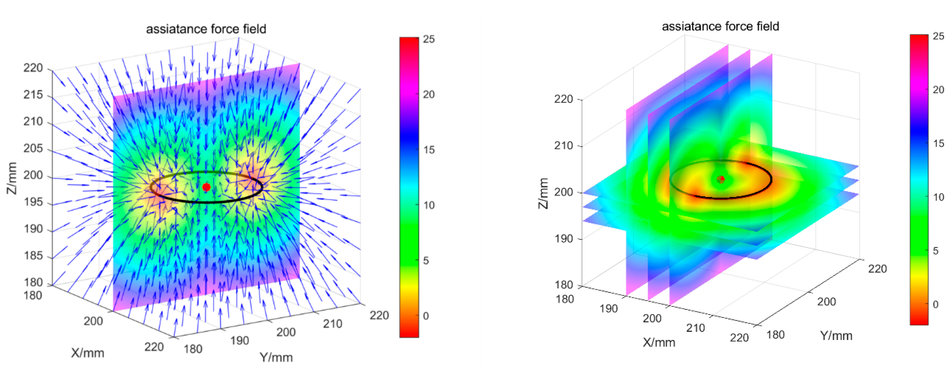
Among the controller presented in this paper, a virtual stiffness gradient field is constructed around the virtual channel to avoid large deviation from the desired path. The controller forms a bounded controllable spatial normal force field around the desired trajectory.
The rest Sections in this paper are arranged as follows: we first describe the development and kinematics modeling of the EULRR in Section 2; the development and implementation of the AAN controller are presented in Section 3; an experiment in different conditions and results are presented in Section 4 to show the effectiveness of the AAN controller, and the conclusions of our research and remarks for future work are presented in Section 5.

2. Development of the End-Effector Upper Limb Rehabilitation Robot (EULRR)

2.1. Mechanical Design of the EULRR

EULRR is a new end-effector upper limb rehabilitation robot that could guide the patient’s arm who have upper limb motor dysfunction to carry out spatial trajectory rehabilitation training. Compared with the unilateral rehabilitation robot, only the robot on the affected side of the patient needs to be used for the upper limb rehabilitation training, and the robot on the other side moves to the safe position designated by us. Conversely, when the other side manipulator is used for rehabilitation training, the manipulator at the opposite side also moves to a safe position. Unlike the unilateral rehabilitation robot, which either needs to adjust the patient’s position or needs to design specific devices to move the base of the robot to adapt to the rehabilitation training for patients with different side motor dysfunction of the upper limb. To illustrate the structural design of EULRR clearly, a three-dimensional SolidWorks model design is given in Figure 1. EULRR mainly consists of the body structure module and the motion assistance module. The body structure module, which is equipped with six universal wheels, is mainly used to support the assistance motion module, as well as the robot control cabinet, the control computer, and the electrical structure. The motion assistance module that consists of two commercial manipulators is installed outside the body structure module and is used to support and assist the patient’s arm to completing rehabilitation training. Each manipulator has 7 DOF (degree of freedom), and each joint is equipped with a torque sensor and a position encoder, which can be realized by the torque control. The load of the manipulator is 7 kg, and the working radius of the manipulator is 800 mm. Two handles are installed at the end of the manipulators, which are used to connect the manipulator with the patient’s hand through the bandage, as shown in Figure 2. The handle in EULRR is mainly used for testing, and further design is needed for actual use in patients’ rehabilitation training.
According to the dual-arm workspace of human upper limbs [34], the motion assistance module of the EULRR designed in this paper is installed horizontally, and the two manipulators are installed at a mutual vertical angle. The base mounting distance between the two manipulators in EULRR is designed based on the anthropometric theory. Kaya et al. [35] suggested that the shoulder width had a mean measurement of 355.8 mm (female) and 389.4 (male) at age 17. In the prototype of the EULRR, the base mounting distance is designed as 520 mm, which can be applied to patients with different shoulder widths. Considering the connection and comfort between the hand of patients and the end of the robot, the end handle width of the EULRR is designed to be 120 mm [36]. Besides, the height of the seat could be adjusted to adapt to the height of different people, and the position of the seat could also be adjusted forward and backward. The display screen is installed on the column of the robot body, which is mainly used for debugging. There is also a removable additional screen for the training scene, placed in front of the patient, which is not shown here.

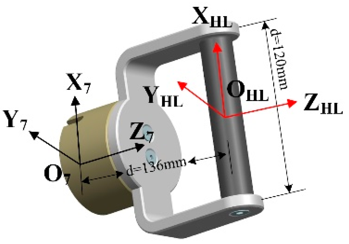
2.2. Kinematics Modeling of EULRR

As shown in Figure 1, only the two manipulators are moving during the rehabilitation training; therefore, the forward kinematics analysis is mainly to study the transformation relationship between the handles coordinate frame and the world coordinate frame. The origin of the world coordinate frame for EULRR is set as the intersection point of the joint axis 1 of the two manipulators (as shown in Figure 1); the base coordinate frame of the manipulators and the end-effector coordinate frame are set at the center of the base of the manipulators and the center of the end-effector, respectively. The link coordinate frames and DH (Denavit & Hartenbrtg) parameters of the manipulator, according to the DH method, are as shown in Figure 3 and Table 1, respectively. The transformation matrix of the handle coordinate frame in the world coordinate frame is shown in Equations (1)–(3).
T H L W o r l d = T O L W o r l d T 0 O L T 7 0 T H L 7 = [ n L o L a L p L 0 0 0 1 ]
T H R W o r l d = T O R W o r l d T 0 O R T 7 0 T H R 7 = [ n R o R a R p R 0 0 0 1 ]
T 7 0 ( q ) = i = 1 7 ( T i i 1 ( q i ) )
where q is the joint position, [ n , o , a ] and p are the orientation matrix and position vector of the handle presented in the world coordinate frame, respectively.

3. Assist-As-Needed Control of the EULRR

3.1. Dynamic Modeling and Impedance Control of Robot

Assume that the studied rehabilitation robot consists of n revolute joints connected with rigid links, then the kinematics Equation of the robot can be expressed as:
x = x ( q )
The differential kinematics can then be written as:
x ˙ = J ( q ) q ˙
x ¨ = J ˙ ( q ) q ˙ + J ( q ) q ¨
where J ( q ) defines the geometric Jacobian, x is the robot cartesian position. Denoting the position, velocity, and acceleration of joints, respectively, the dynamics Equation of the robot in the joint configuration space can be described as follows:
M ( q ) q ¨ + C ( q ,   q ˙ ) q ˙ + G ( q ) + F ( q ˙ ) = τ + J T ( q ) F e x t
where τ R n denotes the vector of applied torques by actuators, M ( q ) R n × n is the inertial matrix, C ( q , q ˙ ) R n × n denotes the centrifugal and Coriolis matrix, G ( q ) R n is the gravity vector, F ( q ˙ ) R n denotes the friction vector, and the F e x t is the external force vector exerted by the user on the end-effector.
Assume that the Jacobian matrix J ( q ) is bounded and full-rank in the operational workspace such that its inverse exists. We can develop the dynamics based on the Cartesian space variable as follows:
M x ( x ) x ¨ + C x ( x ,   x ˙ ) q ˙ + G x ( x ) + F x ( x ˙ ) = J T ( q ) τ + F e x t
where M x ( x ) = J T ( q ) M ( q ) J 1 ( q ) , C x ( x ,   x ˙ ) = J T ( q ) [ C ( q , q ˙ ) M ( q ) J 1 ( q ) J ˙ ( q ) ] J 1 ( q ) , G x ( x ) = J T ( q ) G ( q ) , F x ( x ˙ ) = J T ( q ) F ( q ˙ ) .
Many robot control methods can be realized [37] based on the robot dynamics model, such as position control and force control, among which impedance control is a classical control method. Impedance control was first mentioned by Neville Hogan [24]. In an analogy to electrical systems, he divided physical systems into two types: admittances, which accept effort (e.g., force) inputs and yield effort (e.g., motion) outputs; impedances, which accept motion (e.g., force) inputs and yield effort (e.g., force) output. For the convenience of expression, the control law of impedance control in Cartesian space in a single-degree-of-freedom system can be expressed as:
M x ¨ c u r + D ( x ˙ c u r x ˙ d e s ) + K ( x c u r x d e s ) = F e x t
M = d i a g ( m i ) D = d i a g ( d i ) K = d i a g ( k i ) } i { x , y , z , A , B , C }
where F e s t is the wrench of the end-effector of the robot, x ˙ and x ¨ are the velocity and acceleration of the robot end-effector, x c u r and x d e s are the measured and desired end-effector poses, M is the mass matrix constructed according to the expected motion, and D is the damping coefficient matrix, K is the stiffness coefficient matrix, A , B , C is the Euler angles of the robot end-effector. The robot end-effector behaves as a mass-damper-spring system, both when the robot is driven by an external force or moment or when following a given reference.

3.2. Assist-As-Needed Control Based on Cartesian Impedance Control

For the rehabilitation training in the middle and later stages of rehabilitation of patients with motor dysfunction of the upper limb, they usually have recovered part of active motor ability and consciousness. However, the main muscle groups of the upper limb cannot fully support the upper limbs to complete the rehabilitation training task; that is, the patients have the consciousness of active movement but cannot complete the training task alone, which, to a large extent, hinders the recovery of upper limbs’ motor function. Therefore, rehabilitation robots are required to assist the patient to complete the training task when the patient cannot complete the rehabilitation training task. Generally, the velocity of the patient’s arm during the rehabilitation training is relatively slow, and the study has shown that slow training has a better effect on upper limb motor function than fast training [38]. Therefore, the patient’s movement position is more important than the movement velocity in rehabilitation training. The relationship between the assistance force and the end deviation of the robot according to Equation (9) is:
K ( x c u r x d e s ) = F a s s i s t
An impedance-based control strategy based on Equation (11) is developed in [25,26]; however, the spatial freedom of the patient’s arm during the rehabilitation training is limited. To solve the limited spatial freedom problem, a virtual channel is added around the predetermined rehabilitation trajectory, that is, the spatial free range of motion. The main goal is to assist the patient connected to the end-effector of the robot when he/she is not able to accomplish the task. The fundamental idea is to make the robot fully compliant when the patient is moving along the planned trajectory inside the virtual channel or, alternatively, stiffer when the patient is moving out of the virtual channel. The schematic diagram of the virtual channel is, as shown in Figure 4.
The green area in Figure 4 is the virtual channel, the red curve is the predetermined training trajectory R , and the purple curve is the actual trajectory of the end of the patient’s arm. Since the robot and the patient’s hand are connected through the handle, the actual trajectory of the patient’s hand could be calculated through the joint position sensor of the robot combined with the robot kinematics equation. Assume that P a c t ( x a , y a , z a ) is the actual position of the robot end-effector, P r e f ( x d , y d , z d ) is the expected reference position of the patient during rehabilitation training, and P N N ( x N , y N , z N ) is the nearest point on the training trajectory that is at a distance from the patient’s current position.
For a predetermined trajectory R in the Cartesian space, assume that the P S and P E are the start and end positions of the trajectory, and a cylinder with an adjustable radius R W is added around the trajectory, see Figure 5. Since the reference position P r e f determines the magnitude and direction of the robot’s assistance force, and the end-effector position of the robot and the patient is varying with time, therefore, a search algorithm is needed to define the reference position during the training in real-time. Therefore, an AAN control strategy based on the orthogonal deviation is proposed to calculate the reference position in real-time according to the deviation distance of the patient’s motion position in this paper, as shown in Figure 5. Then, a cylinder region of width R W is defined around the virtual channel, and the space region around the trajectory R is divided into three regions. To better define the reference position, it is necessary to search the smallest Euclidean distance between the target trajectory and the current point of motion P N N :
R : P N N ( R ) P a c t 2 = ! m i n
Then, the reference position is defined according to the spatial geometric distance d between the nearest point P N N and the actual point P a c t :
d = ( i = 1 3 | P N N ( R ) ( i ) P a c t ( i ) | 2 ) 1 2
P r e f : { P a c t d < R W | P a c t P r e f | = 2 ( d R W )      R W < d < 2 R W P N N d > 2 R W
If the patient’s arm is moving inside the virtual channel, as shown in f 3 in Figure 5, the reference point P r e f 3 assisted by the robot is the current position of the patient’s hand P a c t 3 ; if the distance between the position of the patient’s hand and the predetermined trajectory exceeds 2 R W , as shown in f 2 in Figure 5, the reference point for robot-assisted movement is P r e f 2 , i.e., P N N ; when the distance from the position of the patient’s hand to the predetermined trajectory exceeds the channel but does not exceed 2 R W , as shown in f 1 in Figure 5, the reference point for robot motion assistance is P r e f 1 ; if the patient’s hand is at the endpoint of the predetermined trajectory, as shown in f 4 in Figure 5, the reference point of the current position is defined as the endpoint position of the trajectory, and the reference point assisted by the robot is P r e f 4 . For space trajectory R , the Euclidean distance between the current point and the nearest point should be greater than the radius of curvature of the nearest point on the space trajectory:
κ < 1 | P a c t P N N | P a c t W
where κ is the curvature radius of points on the trajectory, and W is the space point set reachable by the robot.
The Euclidean distance d between the patient’s current point and its nearest point should be calculated to determine whether the patient deviates from the virtual channel during the rehabilitation training. If the patient moves through the virtual channel, the robot’s assistance force is calculated by calculating the Euclidean distance L between the patient’s current point and its corresponding reference point. If the patient moves to the endpoint of the predetermined trajectory, the corresponding assistance force should be calculated according to the Euclidean distance between the current point of the patient and the endpoint of the trajectory.
L = ( i = 1 3 | P r e f ( R ) ( i ) P a c t ( i ) | 2 ) 1 2
According to Equation (11), the assistance force field F a s s i s t distributed along the radial direction of the virtual channel is:
F a s s i s t = ( K t u n L ) n
n = P r e f ( R ) P a c t | P r e f ( R ) P a c t |
where the F a s s i s t is the robot assistance force, the K t u n is the diagonal matrix with the stiffness values for the virtual channel. To make the movement of patients in rehabilitation training follow the predetermined trajectory as far as possible and have spatial freedom, a virtual stiffness gradient field is designed within the range of the lateral width R W of the virtual channel, and the gradient of the stiffness gradient field is assumed to be ψ , as shown in Equation (19). When the patient’s hand is moving across the virtual channel, it will be hindered by the gradient field to avoid large position errors, which can further improve the effect of robot assistance. The stiffness value K t u n in Equation (17) can be constructed according to the position of the patient’s hand:
ψ = K 1 K 0 R W
K t u n = { K 0 d R W K 0 + | d R W | ψ      R W < d < 2 R W K 1 d 2 R W
where ψ is the gradient of the stiffness gradient field, K 0 and K 1 are the upper and lower limits of the stiffness gradient field, which can be adjusted according to the needs of patients’ rehabilitation training tasks. Therefore, different stiffness gradient fields can be constructed by adjusting K 0 and K 1 . According to Equations (14) and (20), the robot assistance force during the rehabilitation training of the patient can be calculated as follows:
F a s s i s t = { 0   d R W [ K 0 + | d R W | ψ ] 2 | d R W |      R W < d < 2 R W K 1 d d 2 R W
According to the conversion relation between the wrench at the end of the robot and the joint torques and the dynamic equation of robot, see Equation (7), the torques applied in robot joint can be obtained as follows:
τ a s s i s t = J T ( q ) F a s s i s t
Therefore, given the rehabilitation training trajectory R , there is a controllable assistance force field in the space around the trajectory, and its distribution diagram is as shown in Figure 6.
The simplified version of the control chart of the AAN controller based on the impedance control proposed in this paper can be found in Figure 7. On the right side is the EULRR in interaction with the patient’s arm τ i n t ; the position sensors measure the actual joint angles q a c t that is used to calculate the actual position of the robot end-effector P a c t , which is fed into the visual interface implemented in the Unity game engine (Unity Technologies). The interface gives visual feedback about the end-effector position as well as the start position P S and target position P E , which define the training trajectory. This information is used to calculate the nearest neighbor point P N N , the reference point P r e f , and the channel radius R W , and the channel stiffness K t u n , the stiffness field gradient ψ , and the reference point P r e f of the current position are used to calculate the assistance forces F a s s i s t according to Equation (21). The transposed Jacobian J T ( q ) is used to calculate the corresponding joint torques τ a s s i s t that are used together with the torques from the compensation model τ c o m p (consisting of friction, gravity, and Coriolis compensation) as a reference for the torque-controlled motor drives.

4. Experiments and Results

To verify the AAN controller based on Cartesian impedance control proposed in this paper, a healthy male subject testing experiment was designed in different conditions based on the EULRR.

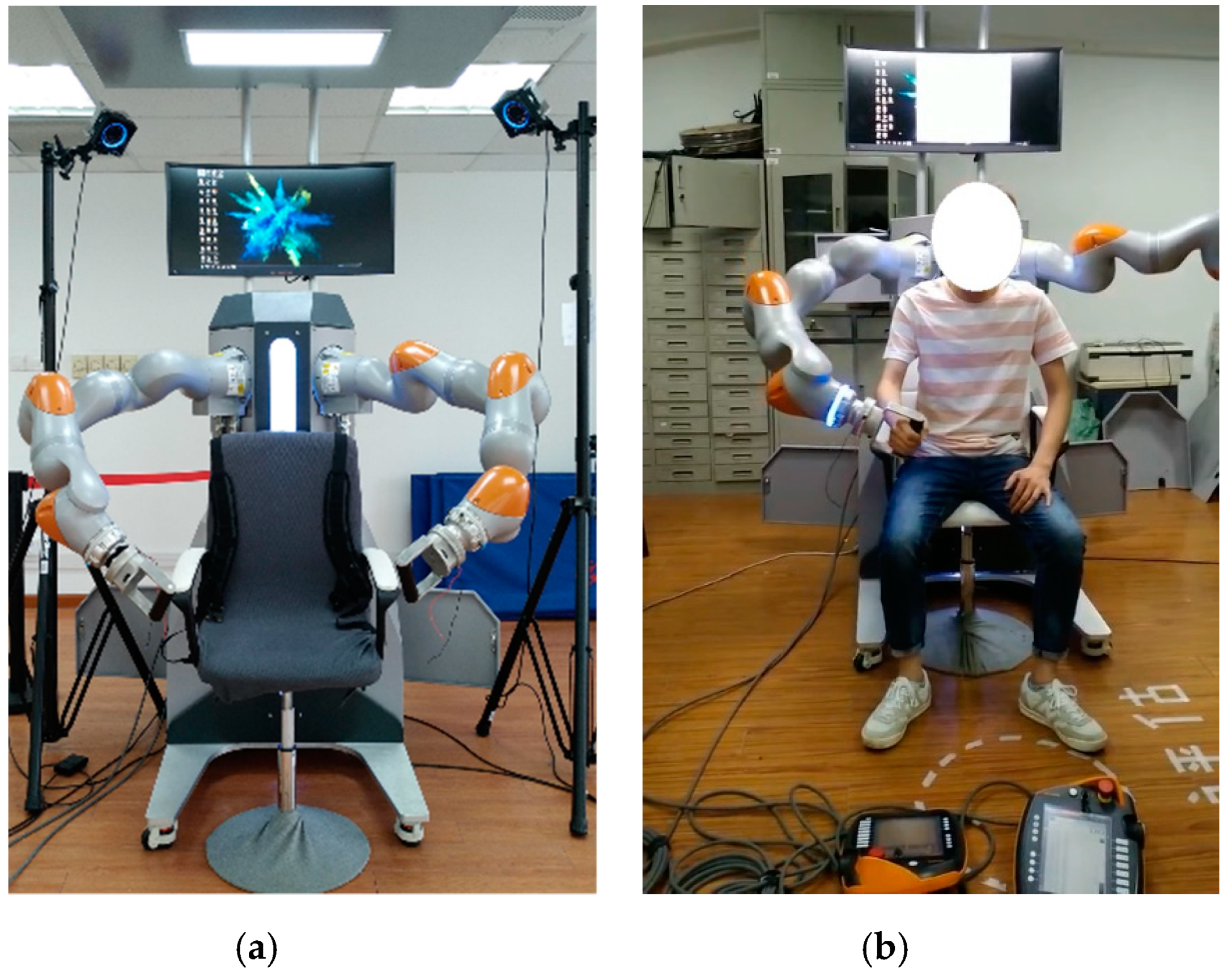
4.1. Experiment Setup

The experimental testing is based on the EULRR, as described in the robot design in Section 2, which is an end-effector upper limb rehabilitation robot that can assist the patient’s arm in achieving spatial rehabilitation training. The manipulator in EULRR is a lightweight robot that can realize real-time external torque control [39] through the FRI (fast research interface) software package [40]. The robot control law can be written as follow:
τ C m d = k j ( q F R I q m e s ) + D ( d j ) + τ F R I + f d y n a m i c s ( q , q ˙ , q ¨ )
where k j is the stiffness matrix in the joint space of the robot, d j is the damping term, and f d y n a m i c s ( q , q ˙ , q ¨ ) is the robot dynamic model. Besides, τ F R I is the expected torque, which is sent in real-time through FRI. During the testing, τ F R I is the equivalent torque of the robot’s assistance force in joint space, calculated by Equation (22).
During the testing, the male subject sat inside the EULRR, as shown in the right of Figure 8. The subject’s hand was connected to the end of the robot through the handle. The test was performed on a healthy 25-year-old subject who was 180 cm tall and weighed 65 kg, assuming that the subject’s right upper arm was the affected side. The manipulator on the same side of the subject’s affected side was used during the training testing, and the manipulator on the other side moved to the home position that is defined as a safe position, as shown in the right of Figure 8. Similarly, when the other side manipulator was used, the opposite manipulator was also moved to the home position. In order to verify the effectiveness of the AAN controller based on the EULRR, the subject was required to complete three tasks, respectively: (a) move the handle of the manipulator freely without any robot assistance under the guidance of the visual scene; (b) testing with the robot assistance without the virtual channel under the guidance of the visual scene; (c) testing with the AAN controller under the guidance of the visual scene. The Unity scene (shown in Figure 9) was used to provide visual guidance and displayed on an extra screen in front of the subject, as shown in the right of Figure 8 (the extra screen is not shown in the picture), in which the white ball in the scene represented the position of the hand of the subject. A circle trajectory was selected during the testing task, as the yellow curve, shown in Figure 9. The three testing tasks were carried out from the initial position, and the moving direction was counterclockwise with the same number of turns. To reduce the impact of motion velocity on the AAN controller, the subject was required to move slowly on the predetermined trajectory, and the robot’s end-effector pose was fixed during the testing, as shown in Figure 8.
For the testing task 1, the subject could move the robot to carry out arbitrary spatial movement without any robot assistance, the robot was in a fully backward driving state, and the subject had fully spatial freedom. For the testing task 2, the stiffness K was set according to the Equation (11) as K = [ 300 , 300 , 300 ] T . The robot would provide assistance force if the subject’s arm deviated from the predetermined trajectory (the yellow curve). In the first 50 s, the subject was asked to perform a normal testing movement. From the 50th second, the subject was asked to deliberately deviate from the predetermined trajectory, that is, to generate a large deviation to fight against the robot. For the testing task 3, the upper and lower limits of the stiffness gradient field were set as K 0 = [ 10 , 10 , 10 ] T and K 1 = [ 300 , 300 , 300 ] T according to the Equation (21), and the radius of the virtual channel was set as R W = 25 mm . The robot did not provide any assistance when the subject’s arm moved within the virtual channel and provided assistance when moving out of the virtual channel. Besides, in the first 50 s, the subject was asked to perform a normal testing movement. From the 50th second, the subject was asked to deliberately deviate from the predetermined trajectory and the virtual channel, that is, to generate a large deviation to fight against the robot. Besides, the robot system runs in the Windows environment, and the data of the robot and the Unity scene are transmitted by UDP. During the three testings, the joint position of the robot and the interaction torque between the robot and the subject measured by the robot joint torque sensors were obtained in real-time.

4.2. Data Analysis

To reduce the influence of noise on the obtained data, a Gaussian lowpass filter was used to deal with the joint position data and the joint torque data during the three testings. To further evaluate the deviation degree of the movement of the subject’s hand, the distance deviation between the actual trajectory and the expected trajectory was calculated:
ε = ( P a c t _ x P N ) 2 + ( P a c t _ y P N ) 2 + ( P a c t _ z P N ) 2
where ε is the calculated distance deviation value. The interaction torque between the robot and the subject measured by the robot joint torque sensor was calculated as follows:
F i n t = J T ( q ) τ i n t
F i n t _ t o t a l = F 2 i n t _ x + F 2 i n t _ y + F 2 i n t _ z
After filtering the data of the robot under three tasks with the Gaussian lowpass filters, the position of the subject’s hand during the three training tasks in the world coordinate frame was obtained based on the forward kinematics of the robot, as shown in Figure 10. The circle area in Figure 10c is the virtual channel constructed by the controller, the red curve is the predetermined trajectory, and the blue one is the actual trajectory of the subject’s hand. The result of the interaction force between the subject and the end-effector of the robot during the three testings is shown in Figure 11. The distance deviation between the actual trajectory and the expected trajectory according to the Equation (24) and the total interaction force between the robot and the subject’s hand according to the Equation (26) were calculated and shown in Figure 12.

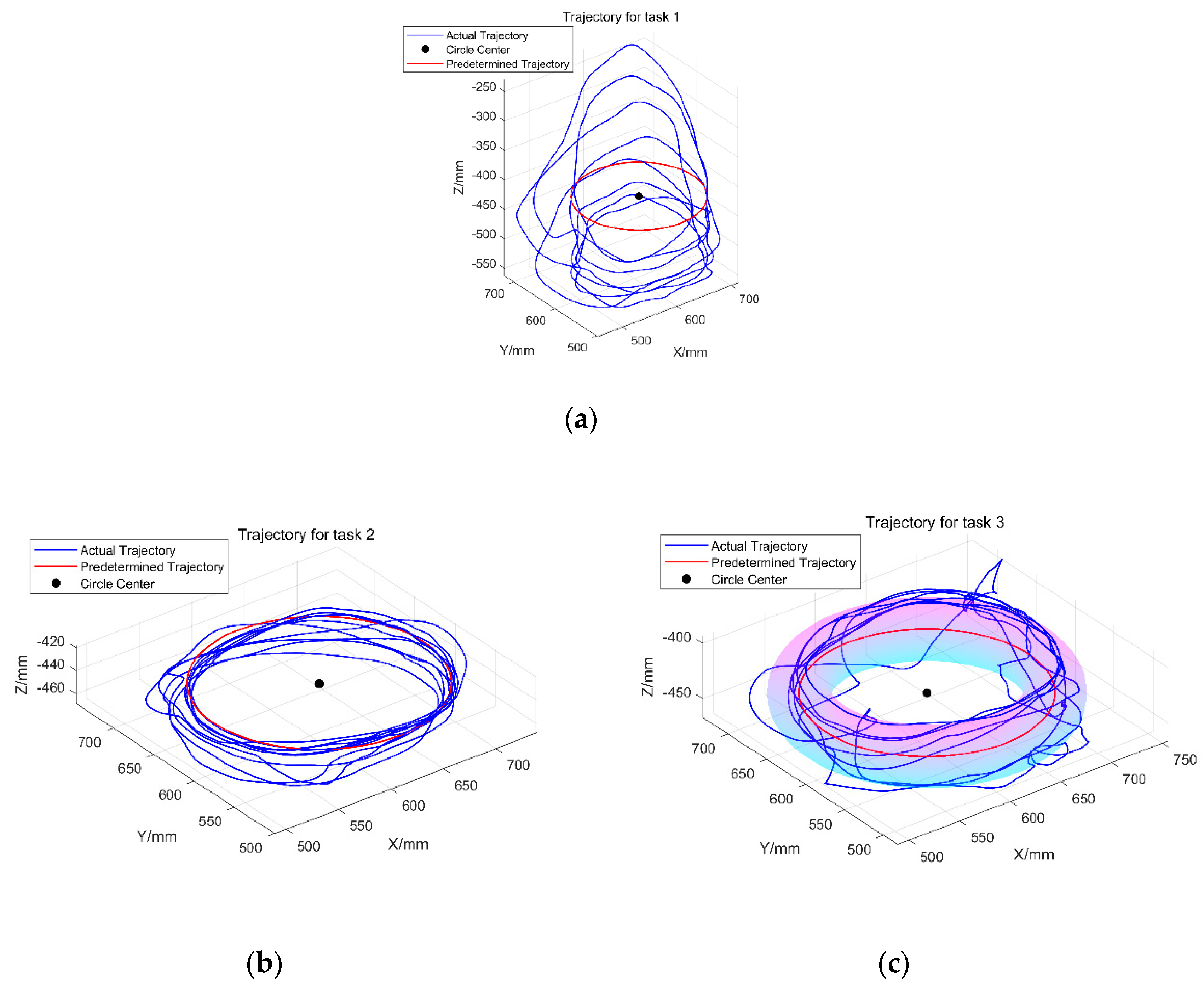
4.3. Experiment Results

According to the experimental results, for the testing task 1, the trajectory of the subject’s hand in the Unity scene deviates from the predetermined trajectory significantly under the guidance of visual, as shown in Figure 10a and Figure 12a, with the maximum deviation reaching 180 mm. The total interaction force between the subject and the robot’s end-effector is below 5N, as shown in Figure 11a and Figure 12a, which is caused by the error of the robot joint torque sensor (2% of the maximum error of sensor). At this time, the robot does not provide assistance force and is in a fully backward driving state, and the subject has complete spatial freedom. For testing task 2, it can be seen from Figure 10b that the trajectory of the subject is concentrated around the predetermined trajectory. Its movement deviates from the predetermined trajectory in the first 50 s and is small, and the total interactive force between the subject and the robot’s end-effector is within 5 N, while the latter part deviates from the predetermined trajectory and is larger (starting from the 50 s), with the total interactive force also becoming larger, highest up to 45 N, as shown in Figure 12b. The robot will provide assistance whenever the subject’s hand deviates from the predetermined trajectory during the testing. The assistance force increases with the increase in deviation distance, and the subject has limited spatial freedom. For the testing task 3, it can be seen from Figure 10c that the subject’s hand moving trajectory is mainly concentrated in the virtual channel. As the radius of the virtual channel is set as 25 mm, the total interaction force between the robot end-effector and the subject’s hand is about 5 N when the male subject’s hand moves in the virtual channel, as shown in Figure 11c and Figure 12c, while the total interaction force increases when the subject’s hand deviates from the virtual channel (starting from the 50 s). The total interaction force between the robot end-effector and the male subject’s hand in the virtual channel is not zero because the moving velocity of the subject is not zero in reality, and the lower limits of the stiffness gradient field are not set to zero. Besides, the posture of the robot is fixed during the test. It can be seen from Figure 11 that the interactive moment between the robot and the subject’s hand is within 2 N.m.
By comparing the deviation degree of the subject in the three testing tasks and the total interaction force between the subject’s hand and the robot’s end-effector, it can be seen that the deviation degree of task 1 is the largest. The robot has no assistance, and the subject has fully spatial freedom. The deviation degree is small in task 2, and the robot’s assistance force increases with the deviation degree. In task 3, the robot does not provide assistance force within the virtual channel, while the assistance force increases with the increase in deviation degree when moving out of the virtual channel. Compared with task 3 and task 1, the robot provides no assistance when the subject’s hand is moving inside the virtual channel while provides assistance when the subject’s hand deviates from the virtual channel in testing task 3. Compared with task 2 and task 3, the subject’s hand in task 3 has fully spatial freedom when moving within the virtual channel. As can be seen from Figure 12b,c, the interaction force between the subject’s hand and the robot’s end-effector in testing task 2 and testing task 3 within 50 s is about 5 N, and the deviation degree in task 3 is significantly larger than that in task 2. The subject in task 3 deviates to a greater degree with the same robot assistance force compared with task 2. The controller in task 3 enables the subject’s hand to have spatial freedom in the allowed virtual channel while provides assistance when moving out of the virtual channel.

5. Discussion and Conclusions

In this paper, we have developed a new end-effector upper limb rehabilitation robot (EULRR) first, which can enable a patient’s arm to carry out a spatial movement, and then have presented a controller to provide motion assistance for assist-as-needed training of the patients with upper limb motor dysfunction. The controller enables the patient’s arm to have spatial freedom by constructing a virtual channel around the predetermined training trajectory. This controller would construct a normal force field around the virtual channel to provide assistance when moving out of the allowed virtual channel. Then, the controller is implemented based on the EULRR and validated through a preliminarily male subject experiment in different conditions. The results show that for the defined motion scenario, the subject has full freedom when moving along the predetermined trajectory within the virtual channel that is constructed by the controller and is assisted by the robot according to the controller when moving out of the virtual channel. Although the EULRR designed in this paper can carry out rehabilitation training on the spatial trajectory, the trajectory in the testing is limited on the horizontal plane in this paper in order to let the subject feel the trajectory in the Unity scene better. However, the controller proposed in this paper does not depend on the choice of training trajectory, and its performance will not be affected for any spatial trajectory.
As a pilot study, the limitations are that only a healthy subject was recruited to do the experiment testing to validate the effectiveness of the proposed controller, and the simple testing Unity scene was used to provide visual guidance for the testing. In the next step, the controller is planned to be used in elderly volunteers and patients with upper limb motor dysfunction to help to increase the intensity of the rehabilitation therapy by assisting the arm movement and by provoking active participation. Besides, we will also develop the Unity game scene and redesign the handle further to collaborate with the proposed controller for the testing task in the close future.

Author Contributions

In this work, L.Z. conceived and designed the experiments; S.G. gave some constructive suggestions; L.Z. performed the experiments; L.Z. and Q.S. analyzed the data; S.G. guided the writing of the article and made some modifications; L.Z. wrote the paper. All authors have read and agreed to the published version of the manuscript.

Funding

This research is supported by the National Natural Science Foundation of China (Grant No. 61973205) and the National Key Research and Development Program of China (Grant No. 2018YFC2001601) and the Science and Technology Commission of Shanghai Municipality (Grant No.18511108302).

Acknowledgments

The authors are grateful to the anonymous reviewers and the Editor for their valuable comments and suggestions on improving this paper.

Conflicts of Interest

The authors declare no conflict of interest.

References

  1. Battiston, B.; Titolo, P.; Ciclamini, D.; Panero, B. Peripheral Nerve Defects: Overviews of Practice in Europe. Hand Clin. 2017, 33, 545. [Google Scholar] [CrossRef] [PubMed]
  2. Bertani, R.; Melegari, C.; Maria, C.; Bramanti, A.; Bramanti, P.; Calabrò, R.S. Effects of robot-assisted upper limb rehabilitation in stroke patients: A systematic review with meta-analysis. Neurol. Sci. 2017, 38, 1561–1569. [Google Scholar] [CrossRef] [PubMed]
  3. Milot, M.; Spencer, S.J.; Chan, V.; Allington, J.P.; Klein, J.; Chou, C.; Bobrow, J.E.; Cramer, S.C.; Reinkensmeyer, D.J. A crossover pilot study evaluating the functional outcomes of two different types of robotic movement training in chronic stroke survivors using the arm exoskeleton BONES. J. Neuroeng. Rehabil. 2013, 10, 112. [Google Scholar] [CrossRef] [PubMed] [Green Version]
  4. Mehrholz, J.; Hädrich, A.; Platz, T.; Kugler, J.; Pohl, M. Electromechanical and robot-assisted arm training for improving generic activities of daily living, arm function, and arm muscle strength after stroke. Cochrane Database Syst. Rev. 2012, 6, CD006876. [Google Scholar]
  5. Roger, G.; Volker, D. Rehabilitation robots for the treatment of sensorimotor deficits: A neurophysiological perspective. J. Neuroeng. Rehabil. 2018, 15, 46. [Google Scholar]
  6. Krebs, H.I.; Ferraro, M.; Buerger, S.P.; Newbery, M.J.; Makiyama, A.; Sandmann, M.; Lynch, D.; Volpe, B.T.; Hogan, N. Rehabilitation robotics: Pilot trial of a spatial extension for MIT-Manus. J. Neuroeng. Rehabil. 2004, 1, 5. [Google Scholar] [CrossRef] [Green Version]
  7. Rui, L.; Amirabdollahian, F.; Topping, M.; Driessen, B.; Harwin, W. Upper Limb Robot Mediated Stroke Therapy—GENTLE/s Approach. Auton. Robots 2003, 15, 35–51. [Google Scholar]
  8. Toth, A.; Nyitrai, D.; Jurak, M.; Merksz, I.; Fazekas, G.; Denes, Z. Safe robot therapy: Adaptation and usability test of a three-position enabling device for use in robot mediated physical therapy of stroke. In Proceedings of the IEEE International Conference on Rehabilitation Robotics, Kyoto, Japan, 23–26 June 2009. [Google Scholar]
  9. Nef, T.; Guidali, M.; Riener, R. ARMin III—Arm therapy exoskeleton with an ergonomic shoulder actuation. Appl. Bionics Biomech. 2009, 6, 127–142. [Google Scholar] [CrossRef] [Green Version]
  10. Sugar, T.G.; He, J.; Koeneman, E.J.; Koeneman, J.B.; Herman, R.; Huang, H.; Schultz, R.S.; Herring, D.E.; Wanberg, J.; Balasubramanian, S. Design and control of RUPERT: A device for robotic upper extremity repetitive therapy. IEEE Trans. Neural Syst. Rehabil. Eng. 2007, 15, 336–346. [Google Scholar] [CrossRef]
  11. Ruffaldi, E.; Barsotti, M.; Leonardis, D.; Bassani, G.; Frisoli, A.; Bergamasco, M. Evaluating Virtual Embodiment with the ALEx Exoskeleton[M]// Haptics: Neuroscience, Devices, Modeling, and Applications; Springer: Heidelberg, Germany, 2014. [Google Scholar]
  12. Akiyama, Y.; Yamada, Y.; Okamoto, S. Interaction forces beneath cuffs of physical assistant robots and their motion-based estimation. Adv. Robot. 2015, 29, 15. [Google Scholar] [CrossRef]
  13. Chang, W.H.; Kim, Y.H. Robot-assisted Therapy in Stroke Rehabilitation. J. Stroke 2013, 15, 174–181. [Google Scholar] [CrossRef] [PubMed]
  14. Proietti, T.; Crocher, V.; Roby-Brami, A.; Jarrasse, N. Upper-limb robotic exoskeletons for neurorehabilitation: A review on control strategies. IEEE Rev. Biomed. Eng. 2016, 9, 4–14. [Google Scholar] [CrossRef] [Green Version]
  15. Babaiasl, M.; Mahdioun, S.H.; Jaryani, P.; Yazdani, M. A review of technological and clinical aspects of robot-aided rehabilitation of upper-extremity after stroke. Disabil. Rehabil. Assist. Technol. 2016, 11, 263–280. [Google Scholar] [CrossRef]
  16. Tucker, M.R.; Olivier, J.; Pagel, A.; Bleuler, H.; Bouri, M.; Lambercy, O.; Millán, J.D.R.; Riener, R.; Vallery, H.; Gassert, R. Control strategies for active lower extremity prosthetics and orthotics: A review. J. NeuroEng. Rehabil. 2015, 12, 1. [Google Scholar] [CrossRef] [Green Version]
  17. Brunnstrom, S.; Sawner, K.A.; Lavigne, J.M. Brunnstrom’s Movement Therapy in Hemiplegia: A Neurophysiological Approach; Lippincott: Philadelphia, PA, USA, 1992. [Google Scholar]
  18. Hogan, N.; Krebs, H.I.; Rohrer, B.; Palazzolo, J.J.; Dipietro, L.; Fasoli, S.E.; Stein, J.; Hughes, R.; Frontera, W.R.; Lynch, D. Motions or muscles? Some behavioral factors underlying robotic assistance of motor recovery. J. Rehabil. Res. Dev. 2006, 43, 605. [Google Scholar] [CrossRef] [PubMed]
  19. Emken, J.L.; Bobrow, J.E.; Reinkensmeyer, D.J. Robotic movement training as an optimization problem: Designing a controller that assists only as needed. In Proceedings of the 9th International Conference on Rehabilitation Robotics, Chicago, IL, USA, 28 June–1 July 2005. [Google Scholar]
  20. Pehlivan, A.U.; Losey, D.P.; Ormalley, M.K. Minimal Assist-as-Needed (mAAN) Controller for Upper Limb Robotic Rehabilitation. IEEE Trans. Robot. 2015, 32, 113–124. [Google Scholar] [CrossRef]
  21. Pehlivan, A.; Sergi, F.; O’Malley, M. A Subject-Adaptive Controller for Wrist Robotic Rehabilitation. IEEE/ASME Trans. Mechatron. 2014, 20, 1338–1350. [Google Scholar] [CrossRef]
  22. Jabbari Asl, H.; Narikiyo, T.; Kawanishi, M. An assist-as-needed control scheme for robot-assisted rehabilitation. In Proceedings of the 2017 American Control Conference (ACC), Seattle, WA, USA, 24–26 May 2017; pp. 198–203. [Google Scholar]
  23. Grosmaire, A.G.; Duret, C. Does assist-as-needed upper limb robotic therapy promote participation in repetitive activity-based motor training in sub-acute stroke patients with severe paresis? Neurorehabilitation 2017, 41, 31–39. [Google Scholar] [CrossRef]
  24. Hogan, N. Impedance control: An approach to manipulation. Part I, II, III. In Proceedings of the American Control Conference, San Diego, CA, USA, 6–8 June 1984. [Google Scholar]
  25. Hui, G.; Misgeld, B.J.E.; Shi, Y.; Ji, L. Dynamic Modeling and Interactive Performance of PARM: A Parallel Upper-Limb Rehabilitation Robot Using Impedance Control for Patients after Stroke. J. Healthc. Eng. 2018, 2018, 8647591. [Google Scholar]
  26. Huo, J.; Zhang, X.; Ji, R.; Liu, Y.; Bi, S.; Ji, L.; Li, C. Development and Implementation of an End-Effector Upper Limb Rehabilitation Robot for Hemiplegic Patients with Line and Circle Tracking Training. J. Healthc. Eng. 2017, 2017, 4931217. [Google Scholar]
  27. Perez-Ibarra, J.C.; Siqueira, A.A.; Silva-Couto, M.A.; de Russo, T.L.; Krebs, H.I. Adaptive Impedance Control Applied to Robot-Aided Neuro-Rehabilitation of the Ankle. IEEE Robot. Autom. Lett. 2018, 4, 185–192. [Google Scholar] [CrossRef]
  28. Cui, X.; Chen, W.; Jin, X.; Agrawal, S.K. Design of a 7-DOF Cable-Driven Arm Exoskeleton (CAREX-7) and a Controller for Dexterous Motion Training or Assistance. IEEE/ASME Trans. Mechatron. 2017, 22, 161–172. [Google Scholar] [CrossRef]
  29. Asl, H.J.; Yamashita, M.; Narikiyo, T.; Kawanishi, M. Field-Based Assist-As-Needed Control Schemes for Rehabilitation Robots. IEEE/ASME Trans. Mechatron. 2020, 25, 2100–2111. [Google Scholar] [CrossRef]
  30. Brokaw, E.B.; Murray, T.; Nef, T.; Lum, P.S. Retraining of interjoint arm coordination after stroke using robot-assisted time-independent functional training. J. Rehabil. Res. Dev. 2011, 48, 299–316. [Google Scholar] [CrossRef]
  31. Proietti, T.; Guigon, E. Modifying upper-limb inter-joint coordination in healthy subjects by training with a robotic exoskeleton. J. Neuroeng. Rehabil. 2017, 14, 55. [Google Scholar] [CrossRef] [Green Version]
  32. Agarwal, P. and Deshpande, A.D. Subject-Specific Assist-as-Needed Controllers for a Hand Exoskeleton for Rehabilitation. IEEE Robot. Autom. Lett. 2018, 3, 508–515. [Google Scholar] [CrossRef]
  33. Khairuddin, I.M.; Sidek, S.N.; Yusof, H.M.; Baarath, K.; Majeed, A.P. Assistive-as-Needed Strategy for Upper-Limb Robotic Systems: An Initial Survey. IOP Conf. Ser. Mater. Sci. Eng. 2017, 260, 12027. [Google Scholar] [CrossRef]
  34. Klopčar, N.; Lenarčič, J. Kinematic Model for Determination of Human Arm Reachable Workspace. Meccanica 2005, 40, 203–219. [Google Scholar] [CrossRef]
  35. Kaya, M.D.; Hasiloglu, A.S.; Bayramoglu, M.; Yesilyurt, H.; Ozok, A.F. A new approach to estimate anthropometric measurements by adaptive neuro-fuzzy inference system. Int. J. Ind. Ergon. 2003, 32, 105–114. [Google Scholar] [CrossRef]
  36. Fransson, C.; Winkel, J. Hand strength: The influence of grip span and grip type. Ergonomics 1991, 34, 881–892. [Google Scholar] [CrossRef]
  37. Jordan, M.; Benitez, L.M.V.; Schmidt, S.; Folgheraiter, M.; Albiez, J. Model-Based Control and Design of a Low-Pressure Fluid Actuation System for Haptic Devices. In Proceedings of the ACTUATOR 2012, 13th International Conference on New Actuators, Bremen, Germany, 18–20 June 2012. [Google Scholar]
  38. Rodrigues, T.A.; Goroso, D.G.; Westgate, P.M.; Carrico, C.; Batistella, L.R.; Sawaki, L. Slow Versus Fast Robot-Assisted Locomotor Training After Severe Stroke. Am. J. Phys. Med. Rehabil. 2017, 96, S165–S170. [Google Scholar] [CrossRef] [PubMed]
  39. Bischoff, R.; Kurth, J.; Schreiber, G.; Koeppe, R.; Hirzinger, G. The KUKA-DLR Lightweight Robot arm—A new reference platform for robotics research and manufacturing. In Proceedings of the ISR 2010 (41st International Symposium on Robotics) and ROBOTIK 2010 (6th German Conference on Robotics), Munich, Germany, 7–9 June 2010. [Google Scholar]
  40. Schreiber, G.; Stemmer, A.; Bischoff, R. The Fast Research Interface for the KUKA Lightweight Robot. In Proceedings of the Workshop on IEEE ICRA 2010 Workshop on Innovative Robot Control Architectures for Demanding (Research) Applications—How to Modify and Enhance Commercial Controllers, Anchorage, AK, USA, 3–8 May 2010. [Google Scholar]
Figure 1. Three-dimension model of the end-effector upper limb rehabilitation robot (EULRR) designed in SolidWork.
Applsci 10 06684 g001
Figure 2. Three-dimension model of the handle.
Applsci 10 06684 g002
Figure 3. The link coordinate frames of the manipulator.
Applsci 10 06684 g003
Figure 4. Schematic diagram of the spatial virtual channel.
Applsci 10 06684 g004
Figure 5. Concept of the virtual tunnel in the assist-as-needed (AAN) control (simplified to a planar case for better understanding).
Applsci 10 06684 g005
Figure 6. The schematic diagram of the assistance force field for a circle trajectory without a virtual channel.
Applsci 10 06684 g006
Figure 7. The control chart of the AAN controller.
Applsci 10 06684 g007
Figure 8. The EULRR prototype and subject testing. (a) the EULRR prototype; (b) the testing of the subject.
Applsci 10 06684 g008
Figure 9. The Unity scene for the testing task.
Applsci 10 06684 g009
Figure 10. The trajectory of the subject’s hand during the three testing tasks. (a) the trajectory of subject’s hand for the task1; (b) the trajectory of subject’s hand for the task2; (c) the trajectory of subject’s hand for the task3.
Applsci 10 06684 g010
Figure 11. The interaction force between the robot and the subject’s hand during the three testing tasks. (a) the interaction force for task 1; (b) the interaction force for task 2; (c) the interaction force for task 3.
Applsci 10 06684 g011aApplsci 10 06684 g011b
Figure 12. The position deviation between the subject’s hand and the desired trajectory, and the total interaction force between the participant’s hand and the robot’s handle during the three testing tasks. (a) the position deviation and the total interaction force for the task 1; (b) the position deviation and the total interaction force for the task 2; (c) the position deviation and the total interaction force for the task 3.
Applsci 10 06684 g012
Table 1. DH (Denavit & Hartenbrtg) parameters of the manipulator.
Link q i / ( ° ) α i / ( ° ) a i / ( mm ) d i / ( mm ) Motion Range/(°)
1 q 1 −900340−170~170
2 q 2 9000−120~120
3 q 3 900400−170~170
4 q 4 −9000−120~120
5 q 5 −900400−170~170
6 q 6 9000−120~120
7 q 7 00152−175~175

