Article

Development and Testing of a Roots Pump for Hydrogen Recirculation in Fuel Cell System

1
School of Energy and Power Engineering, Xi’an Jiaotong University, Xi’an 710049, China
2
Suzhou Academy, Xi’an Jiaotong University, Suzhou 215123, China
3
Yantai Dongde Industry Co., Ltd., 331 Changjiang Road, Yantai 264006, China
*
Author to whom correspondence should be addressed.
Appl. Sci. 2020, 10(22), 8091; https://doi.org/10.3390/app10228091
Submission received: 24 October 2020 / Revised: 10 November 2020 / Accepted: 13 November 2020 / Published: 15 November 2020

Abstract

:
In this paper, the development and testing of a Roots pump with a new rotor profile for hydrogen recirculation in the fuel cell system are presented. The design method of the rotor profile, port position, and structure of the pump is presented. A prototype of a three-lobe Roots pump with helical rotors was fabricated, and its performance was experimentally tested. The measured data show that the effect of the pressure difference on the flow rate and volumetric efficiency of the Roots pump is the most significant, while the effect of suction pressure is limited. It is concluded that the leakage rather than flow resistance is the key factor, which has a major influence on volumetric and isentropic efficiency. The comparison of the performance is also given by the measured results of the same Roots pump working with air, helium, and hydrogen. Finally, the successful integration of the Roots pumps into three PEM fuel cell systems is reported and the optimal operating parameters of the Roots pump in the systems under various loads are also presented. It is found that the performance of the Roots pump integrated into the fuel cell system is better than that measured with pure hydrogen on the test rig. The performance maps composed of all the measured data of the Roots pump are very helpful for the optimal design and operation of the fuel cell system.

HIGHLIGHTS
  • A Roots pump with a new rotor profile for hydrogen recirculation in the PEM fuel cell system is developed.
  • The detailed performance of the prototype was measured by a test rig working with hydrogen.
  • The comparison of the testing results is presented for the same Roots pump working with air, helium, and hydrogen
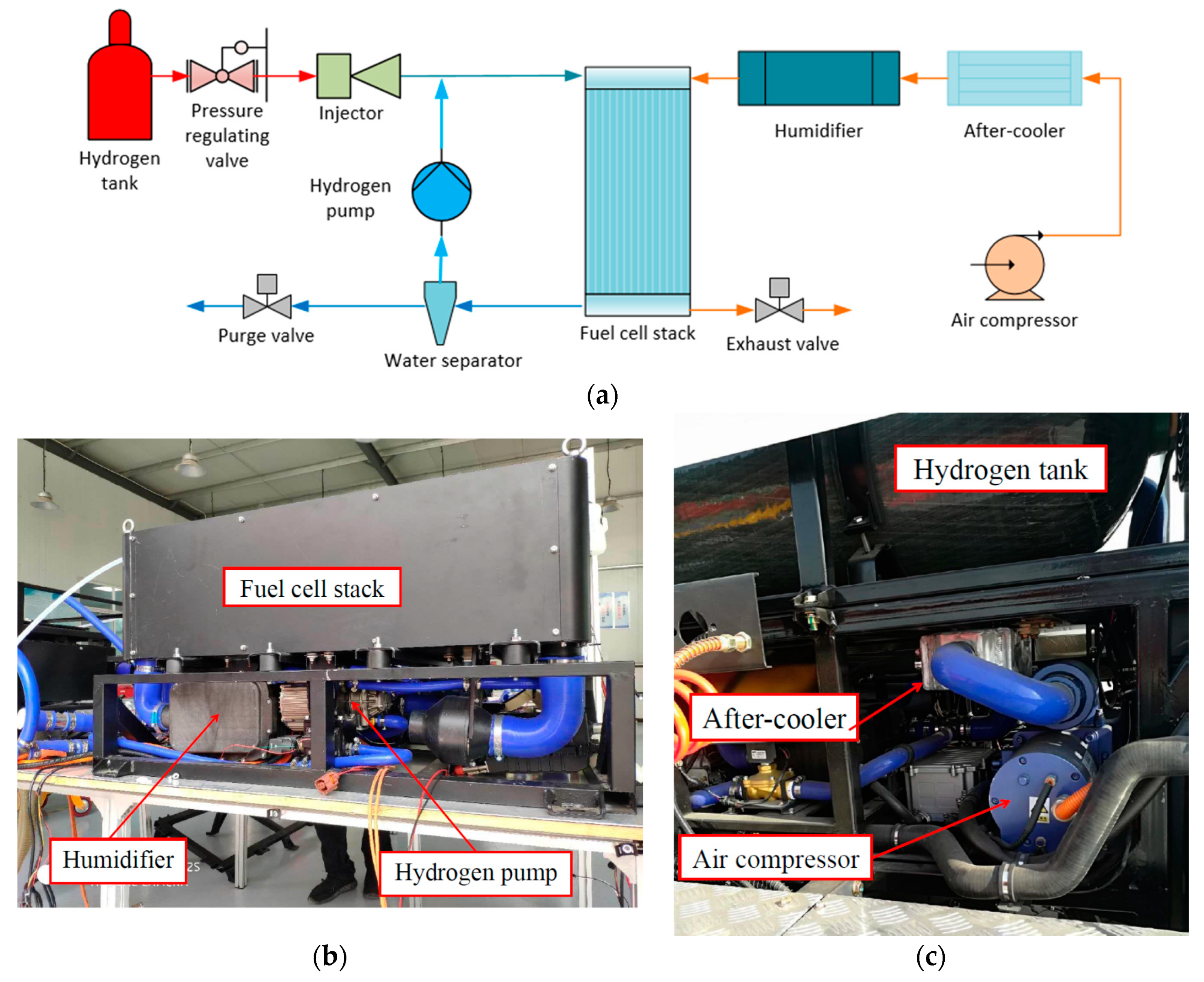
  • The integration of the Roots pump into a PEM fuel cell system is reported.

1. Introduction

As an emerging renewable energy source, the proton exchange membrane (PEM) fuel cell system has great potential in various vehicles and distributed energy systems [1]. In the last three decades, fuel cell technology has made great progress in commercialization. The output power of the PEM fuel cell has been increased steadily, the majority of which are in the range of 60–100 kW, but the cost and durability are still big challenges [2]. On the one hand, a large amount of research on fuel cells has been performed to improve the performance and durability of the stack [3]. On the other hand, developing a simple and efficient Balance of Plant (BOP) subsystem can also increase the life of the fuel cell. BOP mainly includes the anode hydrogen supply, cathode air supply, and thermal management systems [4]. With the increase in the output power and the use of the metal bipolar plate, the operating pressure of the PEM fuel cell system has gradually increased to 200–300 kPa. In these systems, which have a large output power and high operating pressure, the hydrogen recirculating scheme is preferred for the anode hydrogen supply subsystem.
Generally, there are three anode hydrogen supply configurations applied in the PEM fuel cell system: dead-end design, flowing through the structure, and hydrogen recirculation. Compared to the dead-end design or flowing through the structure, the configuration with hydrogen recirculation has advantages such as high power density, low hydrogen consumption, and robust reliability [5]. The hydrogen pump is an important component of the anode hydrogen supply configuration with hydrogen recirculation, the performance of which has a significant impact on the performance of the fuel cell system [6]. A performance map of the hydrogen pump is always needed in the design of a fuel cell system [7]. It is also very important for the realization of the control strategies during the operation of the fuel cell system [8,9].
The performance map of the hydrogen pump is dependent on the specific type of pumps. There are three kinds of pumps used for hydrogen recirculation in the PEM fuel cell systems: electrochemical pump, ejector, and mechanical pump [10]. The electrochemical hydrogen pump dissociates hydrogen into electron and hydrogen ion by using DC voltage. This kind of hydrogen pump has advantages such as small power consumption and low noise [11]. The ejector utilizes the pressure difference between the hydrogen tank and the fuel cell stack as the driving force, which has the advantages of no moving parts, low maintenance cost, and relatively high efficiency [12]. However, the design and control methods of the ejector are complicated because of difficulty in adapting to variable working conditions of fuel cell systems [13]. The mechanical pump increases the hydrogen pressure at the outlet of the fuel cell stack to recirculate it to the inlet, which is driven with a motor powered by the fuel cell system itself. Due to the advantages including multi-phase delivery, easy control, and excellent characteristics in off-design operating conditions, the mechanical pump is widely used in the fuel cell system, especially for automotive applications. Regarding energy efficiency, the system efficiencies of three types of pumps were investigated by Toghyani et al. [10]. The system efficiency of the ejector is highest because of the low parasitic power while, the system of the mechanical compressor has the lowest efficiency. Hence, low system efficiency is the disadvantage of the mechanical compressor. It means that a mechanical hydrogen pump with high performance is in urgent need to be developed.
The mechanical pump is the general name of a group of pumps, which can be divided into several types according to the structures of the key components, such as the regenerative pump, claw pump, scroll pump, and Roots pump. The regenerative pump works at small flow rates and a high compression ratio, providing the advantages of low vibrations, high reliability, and the ability to work without lubrication [14,15]. The claw pump is a rotary positive displacement pump with built-in compression, the main advantages of which include simple construction, structural compactness, and oil-free operation [16]. The scroll pump operates by the meshing of two scrolls with tight clearance, which has the advantages of high efficiency, a wide range of adjustable flow, low noise, and vibration [17,18]. The Roots pump also belongs to the positive displacement machine and its advantages include high reliability, low cost, and permission with reversible rotation. The main disadvantage of the Roots pump is low efficiency since there is no built-in compression within the machine. However, this built-in compression is unimportant in the specific application in the hydrogen recirculation because the pressure difference required is relatively small. Therefore, the Roots pump is a distinguished choice for hydrogen recirculation in the fuel cell system. For example, the hydrogen recirculation pump used in the fuel cell system of the Toyota Mirai is a Roots pump with two straight lobes [19].
Although the Roots pump has already been used for hydrogen recirculation in the fuel cell system, it is hard to find published papers related to the Roots pump for this application except for one primary simulation work from the reference [20]. The majority of the papers about the Roots pump were related to applications as air blowers and vacuum pumps. Nevertheless, all these studies provided invaluable insights and helpful information for the development of the Roots pump for hydrogen recirculation. It was demonstrated by the research that the performance of the Roots pump is strongly influenced by the rotor profile and port position. The sealing performance of Roots vacuum pumps and volume efficiency have been improved by using a profile comprising five arcs [21] or a new design profile using an extended cycloid curve with a variable trochoid ratio [22]. The rotor profile has been optimized based on the calculated backward leakage from each of the four clearances within the Roots vacuum pump, and the results enabled the optimum rotor profiles to be developed [23]. The pressure distribution in a Roots blower with three lobes was simulated by the 2D model and validated by testing data [24]. The transient flow field in the Roots blower was investigated by the Reynolds-Averaged Navier–Stokes computational modeling, which agreed well with the experimental results [25]. Moreover, some research has shown that the performance of the Roots pump with helical rotors and multi-lobes is better than that with straight rotors and two-lobes [26,27,28]. Research has shown that the rotor profile significantly influences the flow field and consequent the performance of the Roots pump.
Therefore, the development of a Roots pump with a new rotor profile for hydrogen recirculation in fuel cell systems and testing of its performance map were the research objectives in this study. The effects of the rotor profile design, port position, and structure of the pump on the performance are discussed and presented in the paper. A prototype of three-lobe Roots pump with helical rotors having a theoretical capacity per rotation of 0.135 L was fabricated, based on which an extensive experimental study was carried out through the test rig built especially for evaluating the performance of the Roots pump. The flow rate and power consumption of the prototype were measured under various operating conditions of rotation speed, suction pressure, and pressure difference. The comparison of the performance for the Roots pump working and being tested with air, helium, and hydrogen is also presented in this paper. Finally, the designed Roots pump was successfully integrated into three PEM fuel cell systems, with output powers of 60, 80, and 110 kW, respectively. The operation performance of the Roots pump under these different loads was analyzed.

2. Development of the Roots Pump

2.1. Specification Parameters
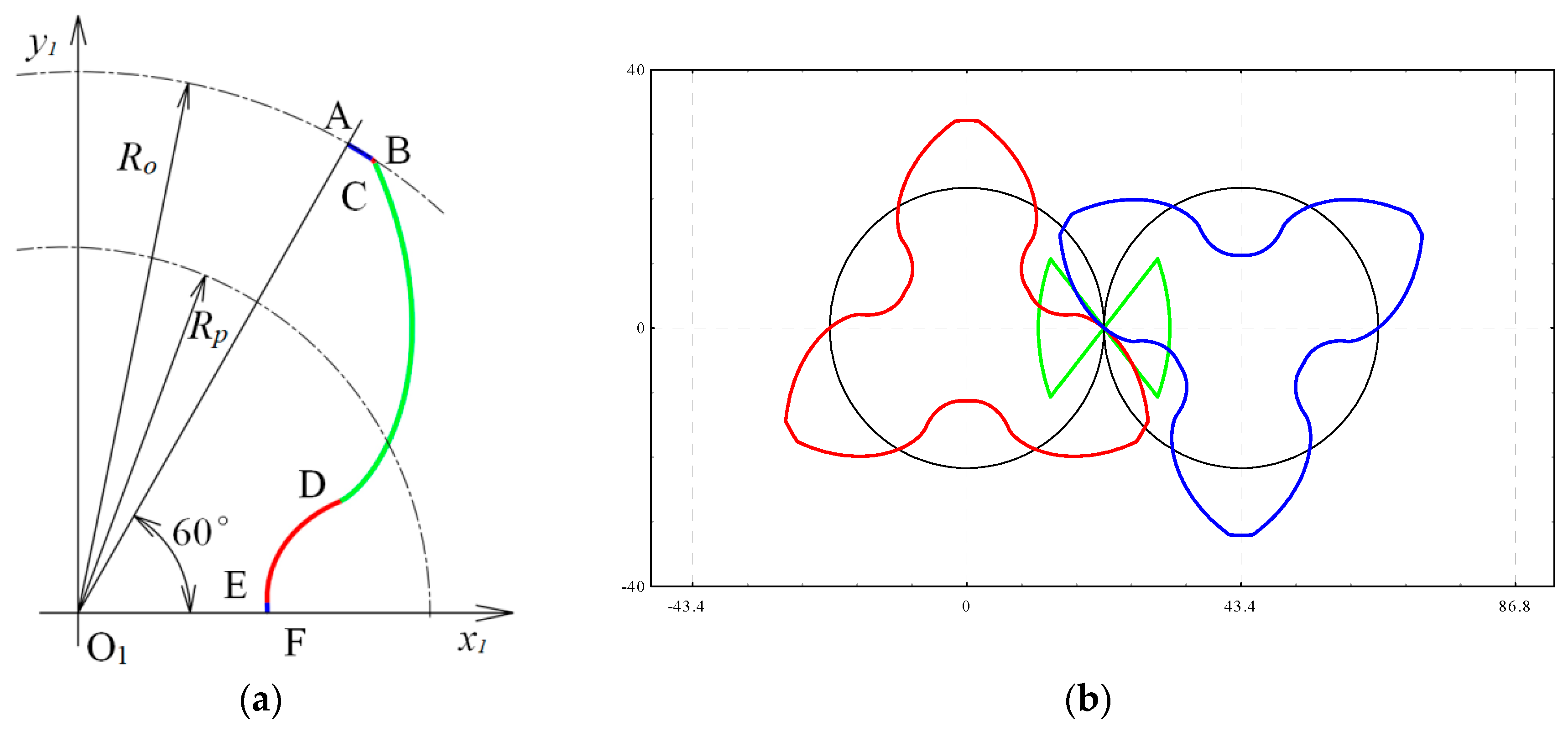
The Roots pump is developed for the fuel cell systems with the output power between 60 and 110 kW under full load operating conditions. The pump is required to operate steadily when the load of the fuel cell is down to 25%. The specification parameters of the Roots pump are listed in Table 1.
The main technical parameters of the Roots pump are designed and listed in Table 2. The hydrogen recirculating pump used in the fuel cell system is required to adapt to a wide flowrate range with high performance, compact volume, and low noise. The size of the Roots pump is dependent on the volume rate and rotation speed. In actuality, for a positive displacement pump or compressor, there is always an optimum speed for the best performance and minimum size. Both the size and cost can be reduced at a significantly high speed, but the performance will become worse due to the high flow losses. Thus, the rated rotation speed is chosen as 8000 rpm for the flowrate demand of 110 kW stack. The flowrate demand under other loads is realized by adjusting the speed. According to the volume flowrate required and the rotation speed determined, the theoretical capacity per rotation of the Roots pump can be obtained. After that, considering the leakage and operational stability of rotors, based on the rotor profile presented in the following section, the diameter of the rotor and center distance between rotors as well as the length of the rotor are determined by referring to the ratio of length to diameter commonly used in engineering for Roots pump. Despite the simple design and low manufacturing cost of Roots pumps using rotors with straight lobes, the performance of the Roots pump can be improved by using helical rotors especially considering the noise and vibration. Thus, the helical rotor is selected for the hydrogen pump because the characteristics of noise and vibration are important to a component in the fuel cell system for various vehicles.

2.2. Rotor Profile

The rotor profile has a significant effect on the performance of the Roots pump. As shown in Figure 1a, the rotor profile is composed of five curves. At the tip of the rotor, there is a circular arc AB which has the same radius as the rotor for reducing the leakage between the rotor tip and the casing. The main part of the profile is an involute curve CD across the pith circle of the rotor. Another circular arc BC is designed to smoothly connect the involute curve CD and the arc AB at the tip. The remaining two curves of the profile DE and EF are the conjugated curves with the two circular arcs BC and AB, respectively. The engage line indicated by the green curve and the whole profile for the Roots pump is shown in Figure 1b. It is illustrated by the shape of the engaged line that the profile continuously and smoothly meshes at all contact points.
The lobe number and the wrap angle are two key parameters having great effects on the performance of the Roots pump. The number of intermediate chambers increases with the lobe number. Hence, the pressure difference decreases with the increment in the lobe number. A decrease in pressure difference results in a reduction of leakage and an increase in volumetric efficiency. Moreover, the manufacturing cost can increase with the enlargement in the lobe number, which should also be taken into account in the design. Based on these considerations, a rotor with three lobes is designed for the Roots pump. Regarding the value of the wrap angle, two aspects of issues need to be considered in the design, which are addressed in this paper. One is the variation in the axial velocity of the gas within the pump from the suction end face to the discharge end face. To eliminate either acceleration or deceleration of the gas, the wrap angle is designed to make the axial velocity of the gas equal to the flow velocity at the suction ports. Another consideration of the wrap angle is the increase in the area of the radial discharge ports. The flow resistance will be smaller with the larger value of the wrap angle since the area is proportional to the increase of the wrap angle.

2.3. Clearances within the Pump

The performance of the Roots pump is influenced significantly by the clearances which can result in gas leakage from the high-pressure chamber to the low-pressure chamber within the machine. The values of these clearances are influenced by many factors such as the thermal expansion of the rotors and casing, the clearance of the bearing, the backlash of the timing-gear, the form and position errors resulted from machining and assembly, etc. The final values of the clearances are reported as follows: clearance between the rotors is 0.1 mm, clearance between the rotor tip and the casing is also 0.1 mm, clearances between the rotor end face and the casing at the suction end and the discharge end are 0.1 and 0.15 mm, respectively.
In general, under the given clearance size, the relative leakage flowrate of the Roots pump can be reduced almost linearly with the increasing of the rotation speed and thus the volumetric efficiency can be improved. Meanwhile, the flow resistances through the suction and discharge ports will rise greatly with increase of the rotation speed and then will cause the reduction of the volumetric efficiency and increase of the power consumption. Therefore, the performance of the Roots pump is determined by the combined effects of leakage and flow resistance.

2.4. Suction and Discharge Ports

The performance of the Roots pump can be affected greatly by the positions of the suction port and discharge ports. Because helical rotors are designed for the Roots pump, the suction port and discharge port have to be located diagonally. The positions and shapes of the suction and the discharge ports are shown in Figure 2a, while the structure of the Roots pump is in Figure 2b. As shown in Figure 2b, the axial suction port is designed on the upper side of the suction end-face, which is connected to the working chamber until the chamber volume is formed by the casing and two helical rotors reach the maximum value. On the other hand, both axial and radial ports are designed for the discharge port. The axial discharge port is fabricated on the lower side of the discharge end-face, and the radial discharge port is on the casing. Due to the fluctuation in the suction pressure of the Roots pump and the small pressure difference, the internal compression cannot occur by the design of the discharge port, which is located at the position where the chamber volume formed by the casing and two helical rotors is going to reduce from the maximum value.

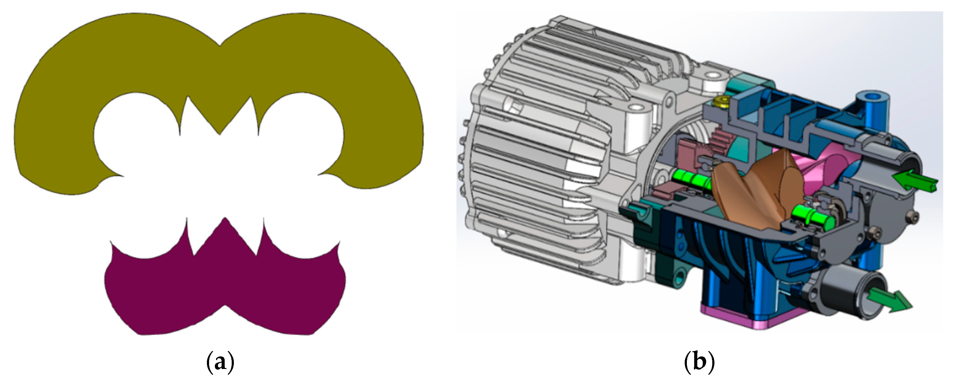
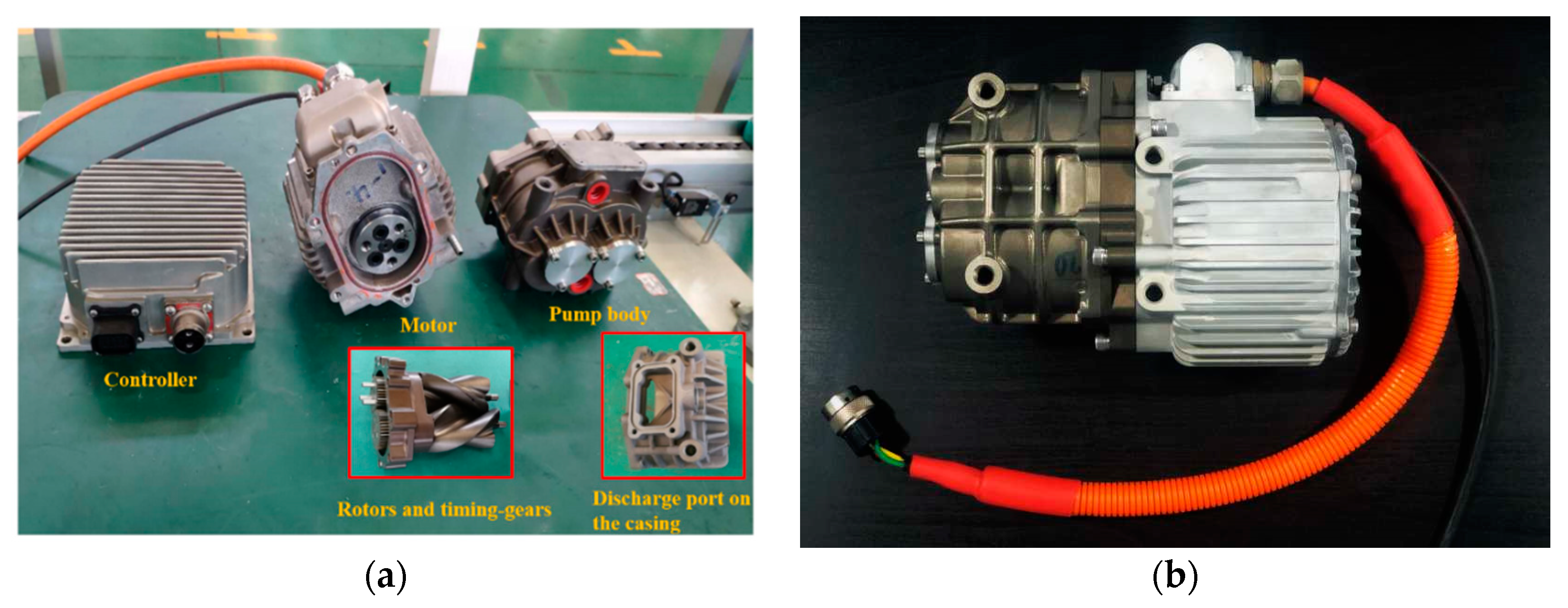
2.5. Prototype of the Roots Pump

The detailed structure of the pump body and the prototype are shown in Figure 3a. The rotors of the Roots pump are driven and separated by the timing-gears and one of the gears is connected to the shaft of the motor. The gears are designed with a small pressure angle and low module in order to limit the change in clearance between the rotors when there is a thermal expansion of the center distance due to the temperature lift. The prototype of the Roots pump is developed in this research work with the semi-hermetic configuration, as can be seen in Figure 3a. The motor and the pump are connected by a flange. The permanent magnet motor is air-cooled and controlled by a controller which is a frequency converter. For the convenience of connecting the pump to the fuel cell system, both the suction and discharge pipe interfaces are axially located on the end-face of the casing. The assembly of the pump and the motor is shown in Figure 3b.

3. Testing of the Roots Pump
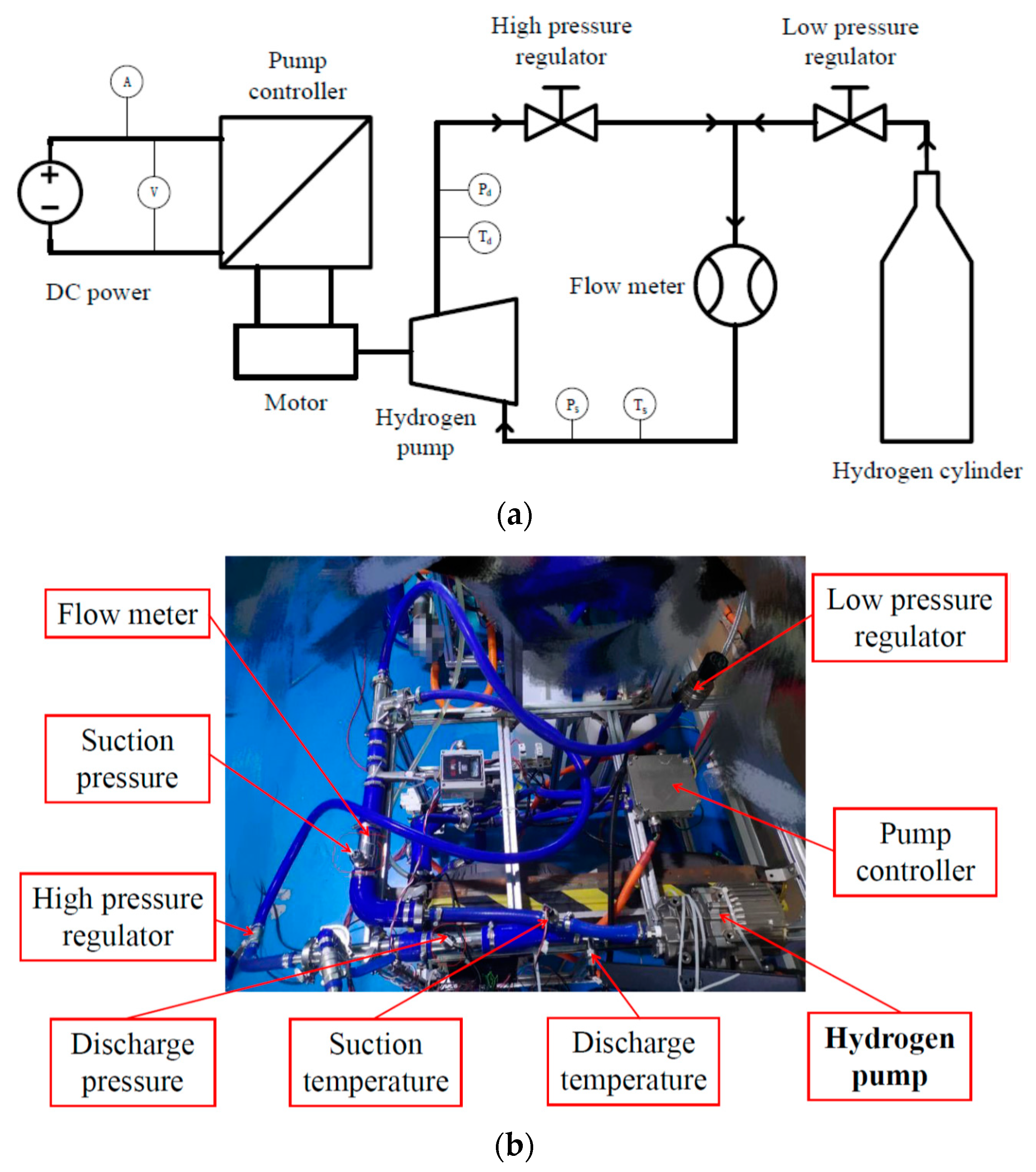
In this study, the working fluids in the Roots pump investigated included air, helium, and hydrogen. Considering the safety and economy, air was firstly used to verify the design and manufacturing quality of the Roots pump. Then, the prototype was test with helium, which is a safe working gas having similar properties to hydrogen. Based on the obtained results, the testing with hydrogen was carried out under a wide range of pressure differences, rotation speeds, and suction pressures. In the following sections, the test of hydrogen is reported in detail and a comparison is also given regarding the performance of the same Roots pump working with air, helium, and hydrogen.

3.1. Test Rig

The schematic diagram and photo of the test rig for measuring the performance of the Roots pump with hydrogen are shown in Figure 4a,b, respectively. Recirculation configuration is designed for the hydrogen circuit because hydrogen is expensive and dangerous. The hydrogen in the high-pressure side flows back to the low-pressure side. All the connecting pipes and measuring equipment are compatible and calibrated to hydrogen. The pressure difference is controlled by the high-pressure regulator in the discharge pipe while the suction pressure is adjusted by charging or discharging gas in the pipes on the suction side through the low-pressure regulator which is connected to a hydrogen cylinder with high pressure. The temperature and pressure of hydrogen are measured by temperature sensors and pressure sensors, respectively. The variable rotation speed of the Roots pump is controlled by the controller and the rotation speed is obtained by the feedback of the controller communication protocol. A Coriolis mass flow meter located on the suction pipe is used to measure the volume flow rate of the pump. Its maximum range is 1000 L/min and uncertainty is smaller than 0.8%. The power input to the motor through the controller is supplied by a DC power source with a constant voltage value of 480 V and the current varied with an accuracy of 0.1 A. The power consumption of the Roots pump can be calculated indirectly according to the measured voltage and the current. The test rig for helium is almost the same as that for hydrogen while the test rig for air is an open circuit and the suction pressure is the ambient pressure.

3.2. Data Measurement

During the testing, the rotation speed of the Roots pump is from 3000 to 9000 rpm, the pressure difference is from 5 to 30 kPa, and the suction pressure is from 180 and 230 kPa. Regarding the suction temperature, it is about 30 °C depending on the pressure difference and rotation speed.
The performance parameters of a Roots pump include volume flow rate, power consumption, volumetric efficiency, and isentropic efficiency. The volumetric efficiency ηv is defined as the ratio of the actual volumetric flow rate Q to the theoretical volume flow rate Qth. A higher volumetric efficiency implies a better performance of the pump. It is calculated by the following equation:
η v = Q / Q t h
Q t h = 2 Z A 0 L n
where Z is the lobe numbers of the rotor, A0 is the area between two lobes of the rotor and the casing, L is the rotor length, and n is the rotation speed of the rotor.
The isentropic efficiency ηis is the ratio of the power consumption with isentropic compression Nis to the actual power consumption N. A higher isentropic efficiency means a more efficient compression process, fewer friction losses in timing-gear and bearings, and higher efficiency of the motor and controller. It is expressed by the equation:
η i s = N i s / N
where N i s is the power consumption with isentropic compression and can be calculated with the equation:
N i s = κ κ 1 P s Q ( ( P d P s ) κ 1 κ 1 )
P d = P s + Δ P
where k is the isentropic index of the gas, P s and P d are the suction and discharge pressure, and Δ P is the pressure difference. This equation indicates that the main factors affecting the power consumption of a Roots pump include the type of gas, suction pressure, and pressure difference.

3.3. Results and Discussion

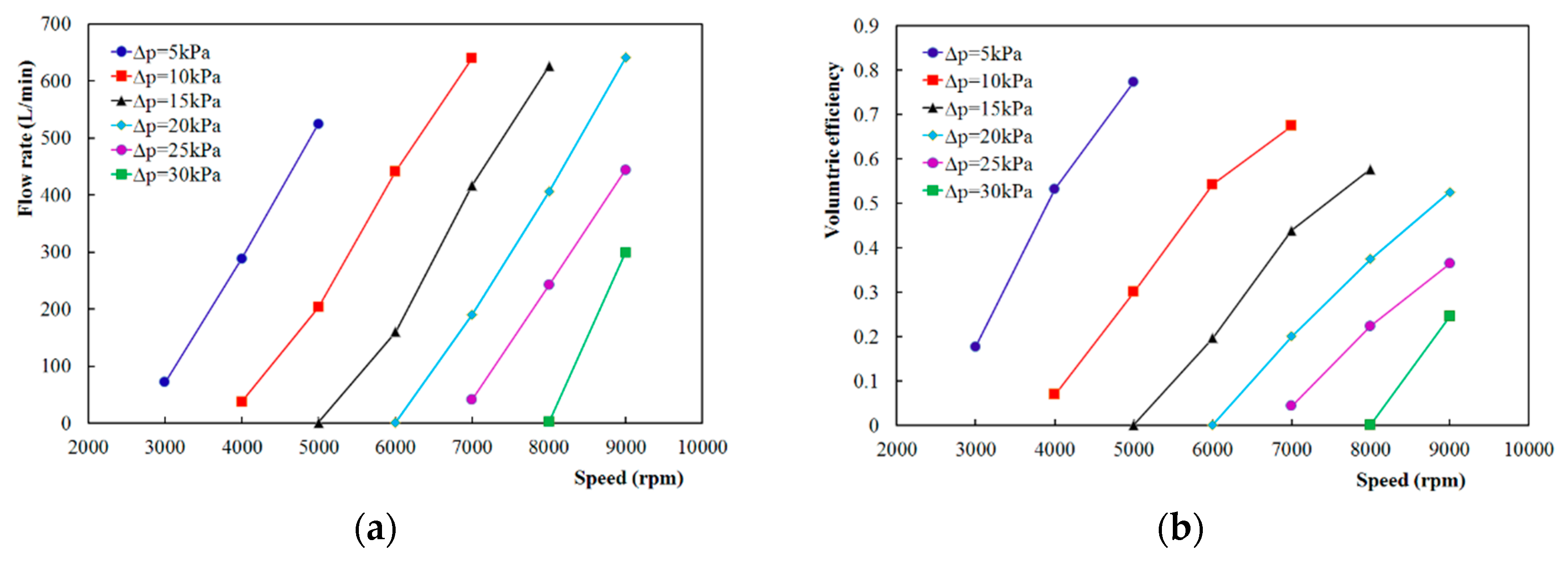
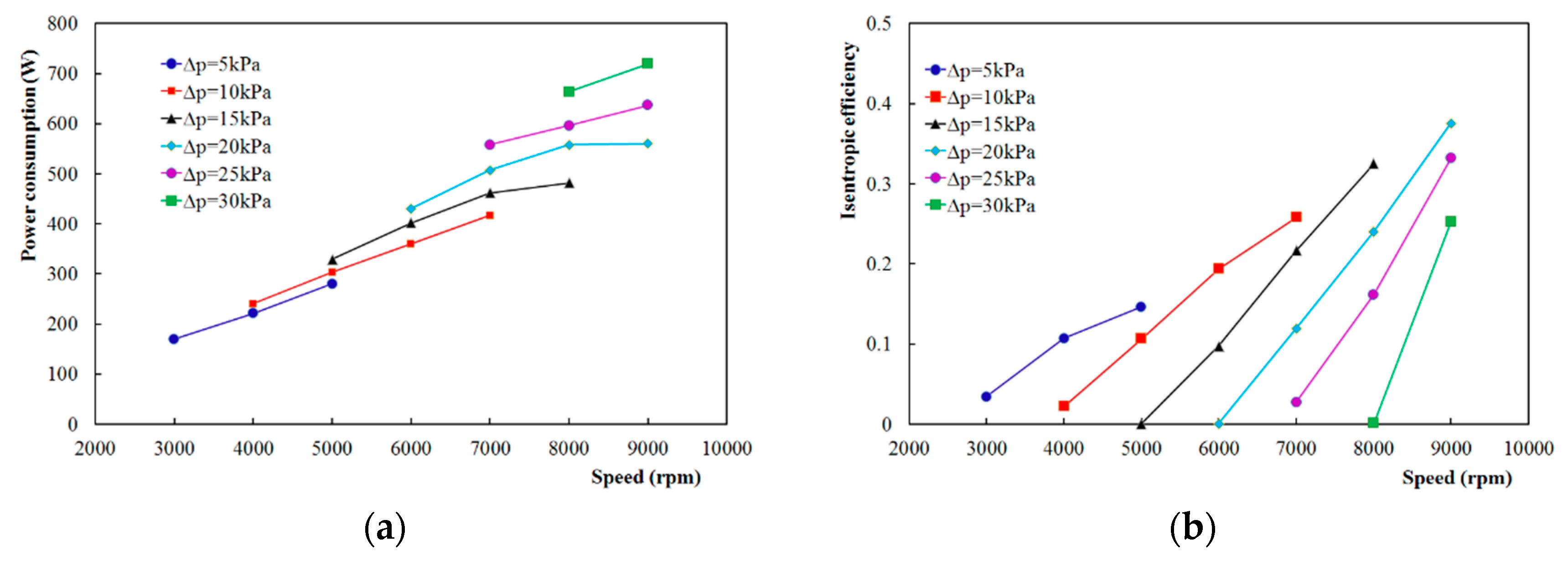
3.3.1. Effect of Pressure Difference

Figure 5a shows the variation in the volume flow rate of the Roots pump with the rotation speed and pressure difference while the suction pressure is kept as 200 kPa. The working gas is pure hydrogen. The volume flow rate varies almost linearly with the rotation speed under a given pressure difference. This is the typical pattern for positive displacement pumps, which means that the flow rate is not coupled with the pressure difference. Thus, the requirements of various flow rates for different fuel cell systems can be satisfied by controlling the rotation speed of the Roots pump. At a certain speed in Figure 5a, the flow rate decreases quickly with the increase in the pressure difference, which becomes zero when the pressure difference is larger than a certain value. This means the leakage is the key factor having a great influence on the performance of the Roots pump and all clearances within the pump should be kept as small as possible.
Figure 5b shows the variation of volumetric efficiency of the Roots pump with the rotation speed and pressure difference while the suction pressure is kept as 200 kPa. It is shown in Figure 5b that the volumetric efficiency increases monotonously with the speed under a certain pressure difference. This implies that the leakage rather than the flow resistance is the key factor, which has a major effect on volumetric efficiency. Otherwise, the volumetric efficiency would decrease at high rotation speed if the flow resistance has significant influence.
Figure 6a shows the variation of power consumption of the Roots pump with the rotation speed and pressure difference while the suction pressure is kept as 200 kPa. Similar to the pattern of flow rate, the power consumption increases almost linearly with the speed under a certain pressure difference. This is also the typical pattern for positive displacement pumps. At a certain speed in Figure 6a, the power consumption increases proportionally with the increase in the pressure difference. This means the power consumption is still high even when the flow rate is very small under a big pressure difference.
Figure 6b shows the variation of isentropic efficiency of the Roots pump with the rotation speed and pressure difference while the suction pressure is kept as 200 kPa. Similar to the pattern of volumetric efficiency, the isentropic efficiency increases sharply with the speed under a certain pressure difference and this again implies the leakage is the key factor having a great effect on the isentropic efficiency. The effect of leakage on the isentropic efficiency is much greater than other factors such as flow resistance, friction losses, and inefficiency of the motor together with frequency inverter.

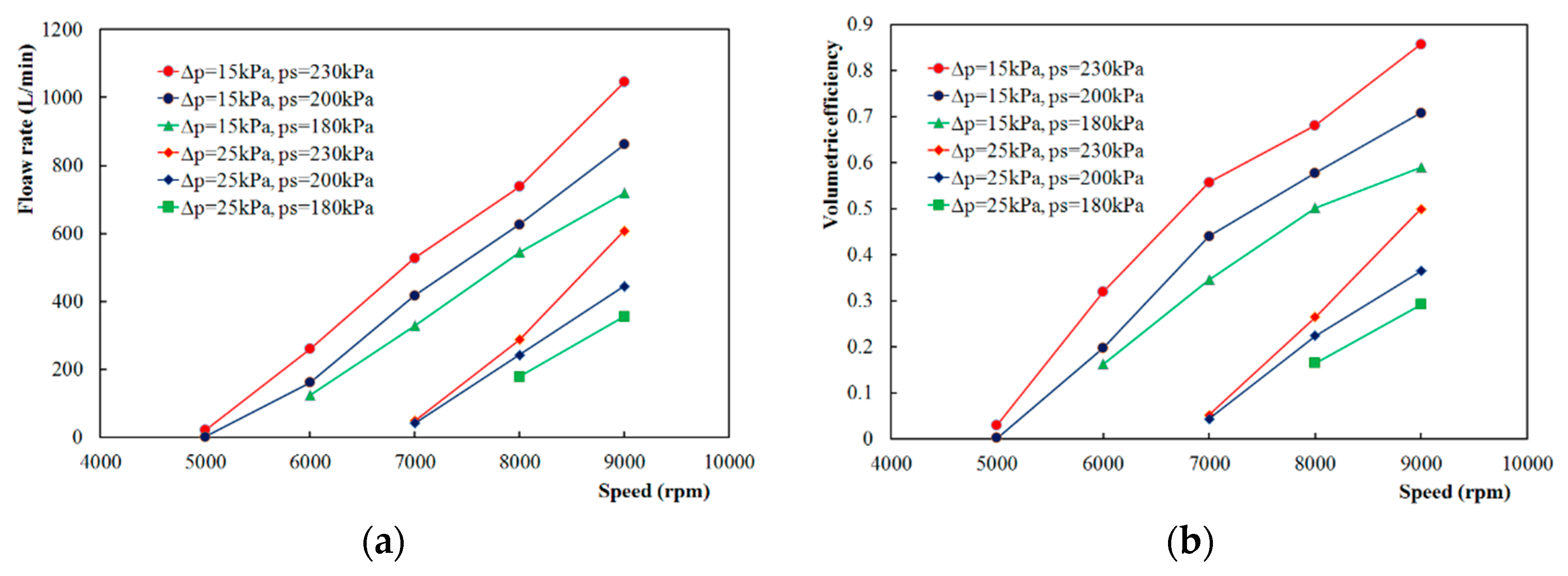
3.3.2. Effect of Suction Pressure

Figure 7a shows the variation in the volume flow rate of the Roots pump with the rotation speed and suction pressure while the pressure differences are 15 and 25 kPa. It can be seen that the flow rate becomes smaller and smaller with a decrease in the suction pressure under the same pressure difference. This is because the pressure ratio increases with the reduction in the suction pressure, which means leakage in the pump will be larger when the pressure ratio becomes higher. It is interesting to find that the variation of volume flow rate with suction pressure is limited when compared to that with pressure difference. The decrease in the flow rate due to the pressure difference from 15 to 25 kPa is much larger than the suction pressure from 230 to 180 kPa. This implies again the pressure difference rather than suction pressure has the dominant influence on the flow rate of the Roots pump.
Figure 7b shows the variation of volumetric efficiency of the Roots pump with the rotation speed and suction pressure while the pressure differences are 15 and 25 kPa. It has a similar pattern as Figure 7a and means that the impact of suction pressure on the volumetric efficiency is less significant than the pressure difference.

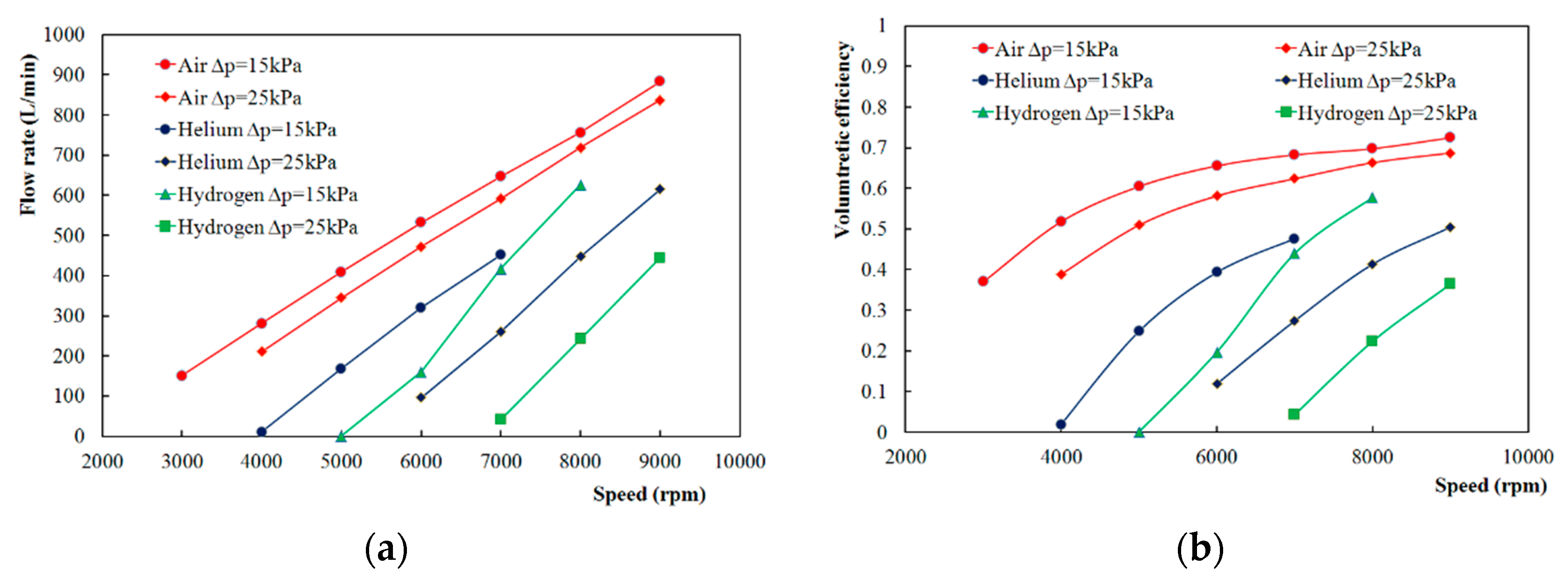
3.3.3. Comparison of Performance with Air, Helium, and Hydrogen

The volume flow rate and volumetric efficiency of the Roots pump working with air, helium, and hydrogen separately are presented and compared in Figure 8. The suction pressure with both helium and hydrogen is 200 kPa while that with air is the ambient pressure. At a certain speed and pressure difference, it can be seen in Figure 8a that the volume flow rate of the Roots pump with air is much higher than that with helium or hydrogen, and the value with helium is also obviously higher than that with hydrogen. Moreover, the reduction of volume flow rate with the increase in pressure difference for hydrogen is larger than helium, and the reduction for helium is larger than air. These experimental results indicate that the performance of the Roots pump is highly sensitive to the properties of the working gas.
Regarding the comparison of volumetric efficiencies shown in Figure 8b, the same variation tendency exists as the volume flow rate. The Roots pump with air has the highest volumetric efficiency, while that with hydrogen has the lowest. The deterioration of the volumetric efficiency by hydrogen is the most serious, while that by air is the least significant. In addition, it can be seen that all the volumetric efficiencies increase with the rotation speed under a certain pressure difference while the values of the increment become smaller when the speed is higher. This means the leakage rather than the flow resistance is the key factor, which has a major effect on the performance of the Roots pump in this application.

4. Integration of the Roots Pump

Based on the testing results on the test rig, the Roots pump developed was then separately integrated into three PEM fuel cell systems with outputs of 60, 80, and 110 kW, respectively. It is validated that the pump can deliver enough hydrogen for the fuel cell systems with different outputs under 100% loads. It is also proved that the Roots pump can operate steadily when the load of the fuel cell systems is down to 25% load. The schematic diagram of the test system and the integration photo of a fuel cell system with the Roots pump is shown in Figure 9. The improvement in the performance of the fuel cell system by integrating the Roots pump developed was observed in tests. The Roots pump operates stably in a wide range of rotation speeds. All the requirements of hydrogen recirculation for the fuel cell systems with outputs of 60, 80, and 110 kW were satisfied with the same Roots pump just by changing its rotation speed. Compared with the type of centrifugal pump such as the regenerative pump, the pressure difference and rotation speed are not coupled together in the Roots pump, which is greatly beneficial to the control of the fuel cell system. When compared with other types of positive displacement pumps such as claw pump and scroll pump, the advantages of the Roots pump include low cost, high efficiency, and robust reliability.
The operating parameters of the Roots pump in PEM fuel cell systems under various loads are listed in Table 3. From the data in Table 3, it can be seen that the ratios of the pump power consumption to fuel cell system power are in the range of 0.77–0.89% with the fuel cell load of 100%, while that is 1.02–1.2% with the fuel cell load of 25%. Moreover, it is interesting to find that the Roots pump is operating with rotation speed in the range of 5400–8000 rpm under the pressure differences of 25–32 kPa. As shown in Figure 5a, there is no hydrogen delivered by the pump under the operating conditions with the combinations of the pressure differences and rotation speeds in Table 3. Comparing the data in Figure 5a and Table 3, it can be found that the performance of the Roots pump integrated into the fuel cell system is better than that measured with pure hydrogen on the test rig. This implies that the performance of the Roots pump is affected greatly by the impurities, such as water vapor and nitrogen, which exist inevitably in the anode circuit of the PEM fuel cell system. This might be because the water vapor and nitrogen are helpful for reducing the leakage within the Roots pump due to their higher mole mass and larger dynamic viscosity than that of the pure hydrogen. Thus, it is suggested that more in-depth research work should be carried out to investigate the anode purge strategy and the effects of the impurities on the performance of the Roots pump in the future.

5. Conclusions

A Roots pump with a new rotor profile for hydrogen recirculation in the PEM fuel cell system was developed and integrated into the PEM fuel cell system successfully. Extensive testing was carried out to evaluate the performance of the Roots pump. The performance maps composed of all the measured data of the Roots pump are very helpful to the design and operation of the fuel cell system. The detailed conclusions are as follows:
(1)
The volume flow rate varies almost linearly with the rotation speed. The requirements of various flow rates for different fuel cell systems can be satisfied by controlling the rotation speed of the Roots pump.
(2)
The effect of the pressure difference on the flow rate and volumetric efficiency of the Roots pump is significant, and the effect of the suction pressure is limited.
(3)
Leakage is the key factor which has a major influence on the volumetric and isentropic efficiency of the Roots pump, while the impact of flow resistance is insignificant.
(4)
The performance of the Roots pump is highly sensitive to the property of the working gas. The measured values of volume flow rate and volumetric efficiency are quite different when the same Roots pump operates with air, helium, and hydrogen.
(5)
The performance of the Roots pump integrated into the fuel cell system is better than that measured with pure hydrogen on the pump test rig. This implies that the effects of the water and nitrogen that existed inevitably in the recirculating hydrogen on the performance of the Roots pump are worth studying further.

Author Contributions

L.X. and J.F. conceived and designed the experiments; W.C. and Z.X. performed the experiments; L.X. and J.F. analyzed the data; X.P. and W.C. contributed materials and analysis tools; J.F. and L.X. wrote the paper. All authors have read and agreed to the published version of the manuscript.

Funding

This work was supported by the National Key Research and Development Program of China (Grant No. 2018YFB0105303) and National Natural Science Foundation of China (Grant No. 51976154).

Conflicts of Interest

The authors declare no conflict of interest.

Abbreviations

A0Area between two lobes of the rotor and the casing, mm2
kIsentropic index
LRotor length, mm
nRotation speed of the rotor, rpm
PPressure, kPa
ΔPPressure difference, kPa
QVolume flow rate, L/min
RoTip radius, mm
RpPith radius, mm
NPower consumption, W
Zlobe numbers of the rotor
Greek symbols
ηisIsentropic efficiency
ηvVolumetric efficiency
Subscripts
dDischarge
sSuction
thTheoretical

References

  1. Wilberforce, T.; Alaswad, A.; Palumbo, A.; Dassisti, M.; Olabi, A. Advances in stationary and portable fuel cell applications. Int. J. Hydrog. Energy 2016, 41, 16509–16522. [Google Scholar] [CrossRef] [Green Version]
  2. Dubau, L.; Castanheira, L.; Maillard, F.; Chatenet, M.; Lottin, O.; Maranzana, G.; Dillet, J.; Lamibrac, A.; Perrin, J.-C.; Moukheiber, E.; et al. A review of PEM fuel cell durability: Materials degradation, local heterogeneities of aging and possible mitigation strategies. Wiley Interdiscip. Rev. Energy Environ. 2014, 3, 540–560. [Google Scholar] [CrossRef]
  3. Jahnke, T.; Futter, G.; Latz, A.; Malkow, T.; Papakonstantinou, G.; Tsotridis, G.; Schott, P.; Gerard, M.; Quinaud, M.; Quiroga, M.A.; et al. Performance and degradation of Proton Exchange Membrane Fuel Cells: State of the art in modeling from atomistic to system scale. J. Power Sources 2016, 304, 207–233. [Google Scholar] [CrossRef] [Green Version]
  4. Wang, Y.; Diaz, D.F.R.; Chen, K.S.; Wang, Z.; Adroher, X.C. Materials, technological status, and fundamentals of PEM fuel cells—A review. Mater. Today 2020, 32, 178–203. [Google Scholar] [CrossRef]
  5. Shen, K.-Y.; Park, S.; Kim, Y.-B. Hydrogen utilization enhancement of proton exchange membrane fuel cell with anode recirculation system through a purge strategy. Int. J. Hydrog. Energy 2020, 45, 16773–16786. [Google Scholar] [CrossRef]
  6. Shao, Y.; Xu, L.; Zhao, X.; Li, J.; Hu, Z.; Fang, C.; Hu, J.; Guo, D.; Ouyang, M. Comparison of self-humidification effect on polymer electrolyte membrane fuel cell with anodic and cathodic exhaust gas recirculation. Int. J. Hydrog. Energy 2020, 45, 3108–3122. [Google Scholar] [CrossRef]
  7. Kim, M.S.; Kim, D.K. Parametric study on dynamic heat and mass transfer response in polymer electrolyte membrane fuel cell for automotive applications. Appl. Therm. Eng. 2020, 167, 114729. [Google Scholar] [CrossRef]
  8. He, J.; Choe, S.-Y.; Hong, C.-O. Analysis and control of a hybrid fuel delivery system for a polymer electrolyte membrane fuel cell. J. Power Sources 2008, 185, 973–984. [Google Scholar] [CrossRef]
  9. He, H.; Quan, S.; Wang, Y.-X. Hydrogen circulation system model predictive control for polymer electrolyte membrane fuel cell-based electric vehicle application. Int. J. Hydrog. Energy 2020, 45, 20382–20390. [Google Scholar] [CrossRef]
  10. Toghyani, S.; Afshari, E.; Baniasadi, E. A parametric comparison of three fuel recirculation system in the closed loop fuel supply system of PEM fuel cell. Int. J. Hydrog. Energy 2019, 44, 7518–7530. [Google Scholar] [CrossRef]
  11. Toghyani, S.; Baniasadi, E.; Afshari, E. Performance analysis and comparative study of an anodic recirculation system based on electrochemical pump in proton exchange membrane fuel cell. Int. J. Hydrog. Energy 2018, 43, 19691–19703. [Google Scholar] [CrossRef]
  12. Feng, J.; Han, J.; Hou, T.; Peng, X. Performance analysis and parametric studies on the primary nozzle of ejectors in proton exchange membrane fuel cell systems. Energy Sources Part A Recover. Util. Environ. Eff. 2020. [Google Scholar] [CrossRef]
  13. Han, J.; Feng, J.; Hou, T.; Peng, X. Performance investigation of a multi-nozzle ejector for proton exchange membrane fuel cell system. Int. J. Energy Res. 2020, 1–18. [Google Scholar] [CrossRef]
  14. Badami, M.; Mura, M. Theoretical model with experimental validation of a regenerative blower for hydrogen recirculation in a PEM fuel cell system. Energy Convers. Manag. 2010, 51, 553–560. [Google Scholar] [CrossRef]
  15. Badami, M.; Mura, M. Leakage effects on the performance characteristics of a regenerative blower for the hydrogen recirculation of a PEM fuel cell. Energy Convers. Manag. 2012, 55, 20–25. [Google Scholar] [CrossRef]
  16. Wang, J.; Jiang, X.; Cai, Y. Investigation of a novel circular arc claw rotor profile for claw vacuum pumps and its performance analysis. Vacuum 2015, 111, 102–109. [Google Scholar] [CrossRef]
  17. Zhang, Q.; Feng, J.; Wen, J.; Peng, X. 3D transient CFD modelling of a scroll-type hydrogen pump used in FCVs. Int. J. Hydrog. Energy 2018, 43, 19231–19241. [Google Scholar] [CrossRef]
  18. Zhang, Q.; Feng, J.; Zhang, Q.; Peng, X. Performance prediction and evaluation of the scroll-type hydrogen pump for FCVs based on CFD–Taguchi method. Int. J. Hydrog. Energy 2019, 44, 15333–15343. [Google Scholar] [CrossRef]
  19. Konno, N.; Mizuno, S.; Nakaji, H.; Ishikawa, Y. Development of Compact and High-Performance Fuel Cell Stack. SAE Int. J. Altern. Powertrains 2015, 4, 123–129. [Google Scholar] [CrossRef]
  20. Xing, L.; He, Y.; Wen, J.; Peng, X. Three-dimensional CFD Modelling of a Roots Blower for Hydrogen Recirculation in Fuel Cell System. In 2018 International Compressor Engineering Conference; Purdue University: West Lafayette, IN, USA, 2018; p. 2562. Available online: https://docs.lib.purdue.edu/icec/2562 (accessed on 21 December 2018).
  21. Wang, P.-Y.; Fong, Z.-H.; Fang, H.S. Design constraints of five-arc Roots vacuum pumps. Proc. Inst. Mech. Eng. Part C J. Mech. Eng. Sci. 2002, 216, 225–234. [Google Scholar] [CrossRef]
  22. Hsieh, C.-F.; Hwang, Y.-W. Study on the High-Sealing of Roots Rotor with Variable Trochoid Ratio. J. Mech. Des. 2006, 129, 1278–1284. [Google Scholar] [CrossRef]
  23. Burmistrov, A.; Belyaev, L.; Ossipov, P.; Fomina, M.; Khannanov, R. Combined experimental and calculation study of conductance of Roots pump channels. Vacuum 2001, 62, 331–335. [Google Scholar] [CrossRef]
  24. Sun, S.-K.; Zhao, B.; Jia, X.-H.; Peng, X.-Y. Three-dimensional numerical simulation and experimental validation of flows in working chambers and inlet/outlet pockets of Roots pump. Vacuum 2017, 137, 195–204. [Google Scholar] [CrossRef]
  25. Singh, G.; Sun, S.; Kovacevic, A.; Li, Q.; Bruecker, C. Transient flow analysis in a Roots blower: Experimental and numerical investigations. Mech. Syst. Signal Process. 2019, 134, 106305. [Google Scholar] [CrossRef]
  26. Mimmi, G.; Pennacchi, P. Compression Load Dynamics in a Special Helical Blower: A Modeling Improvement. J. Mech. Des. 1999, 123, 402–407. [Google Scholar] [CrossRef]
  27. Yao, L.; Ye, Z.; Dai, J.S.; Cai, H. Geometric analysis and tooth profiling of a three-lobe helical rotor of the Roots blower. J. Mater. Process. Technol. 2005, 170, 259–267. [Google Scholar] [CrossRef]
  28. Hsieh, C.-F.; Zhou, Q.-J. Fluid analysis of cylindrical and screw type Roots vacuum pumps. Vacuum 2015, 121, 274–282. [Google Scholar] [CrossRef]
Figure 1. Profile of the Roots pump: (a) composing curves; and (b) profile and engage line.
Applsci 10 08091 g001
Figure 2. (a) Suction and discharge ports; and (b) structure of the pump.
Applsci 10 08091 g002
Figure 3. Prototype of the Roots pump: (a) components of the pump body, motor, and controller; and (b) assembly of the pump body and motor.
Applsci 10 08091 g003
Figure 4. Test rig for Roots pump working with hydrogen: (a) schematic diagram; and (b) photo of the test rig.
Applsci 10 08091 g004
Figure 5. Effect of pressure difference on the performance: (a) flow rate; and (b) volumetric efficiency.
Applsci 10 08091 g005
Figure 6. Effect of pressure difference on the performance: (a) power consumption; and (b) isentropic efficiency.
Applsci 10 08091 g006
Figure 7. Effect of suction pressure on the performance: (a) flow rate; and (b) volumetric efficiency.
Applsci 10 08091 g007
Figure 8. Comparison of performance with air, helium, and hydrogen: (a) flow rate; and (b) volumetric efficiency.
Applsci 10 08091 g008
Figure 9. The schematic diagram and the integration photo of a fuel cell system with the Roots pump: (a) The schematic diagram of the test system (b) Photo of the fuel cell stack and hydrogen pump (c) Photo of the air supply system
Applsci 10 08091 g009
Table 1. Specification parameters of the Roots pump.
ParametersValue
Volume flow rate (L/min)500
Suction temperature (°C)80
Suction pressure (kPa)180–220
Pressure difference (kPa)>20
Table 2. Technical parameters of the Roots pump.
ParametersValue
Lobes of rotor3
Center distance between the rotors(mm)43.4
Outside diameter of rotor(mm)64.2
Length of the rotor (mm)40
Wrap angle of the rotor (°)95
Theoretical capacity per rotation (L)0.135
Rated rotation speed of the rotor (rpm)8000
Tip peripheral speed of the rotor(m/s)26.9
Theoretical volume flow rate (L/min)1082
Table 3. Operating parameters of the Roots pump integrated into fuel cell systems.
ParametersValue
Load of the fuel cell100%25%
Power of the fuel cell (kW)6080110152027.5
Pressure difference (kPa)2529.532109.613
Power consumption of the Roots pump (W)535695850180235280
Rotation speed of the Roots pump (rpm)540070008000300046005500
Publisher’s Note: MDPI stays neutral with regard to jurisdictional claims in published maps and institutional affiliations.

