1. Introduction
Producing electricity from fossil fuels such as coal, natural gas and oil has turned out to be neither affordable long-term nor environmentally friendly [
1]. Therefore, sustainable and virtually endless alternative Renewable Energy Sources (RESs) have been identified, the most popular including sun, wind, water and geothermal.
According to the last report from the European Commission’s science and knowledge service [
2], solar power represents the largest share of all the investments in renewable energies, accounting for 42.5% of the total. Global installed Photovoltaic (PV) capacity reached 222 GigaWatts(GW) at the end of 2015 and is expected to rise further to 4500 (GW) by 2050 [
3]. In addition, with estimates implying a 68% increase in average annual PV investments until 2050, PV plants are expected to accelerate even more [
4].
In a PV plant, a PV panel converts the sun’s energy into Direct Current (DC). A solar inverter converts the low voltage DC coming from a panel into Alternating Current (AC), which is then exported to the grid. While traditional solar inverters simply feed solar power into the grid, smart solar inverters dynamically work with the grid to increase its resilience, reliability, safety and security [
5,
6]. Smart solar inverters make autonomous decisions to keep the grid stable and reliable as more distributed energy resources come online. Instead of just feeding power into the grid, smart solar inverters have two-way communication with it [
7,
8]. Smart solar inverters can perform specific grid-supportive functionalities related to voltage, frequency, communications and controls.
There are many smart solar inverters available on the market. In this work we specifically focus on the so-called (smart) string inverters. A string inverter is a device powered by one or more strings (i.e., arrays) of PV panels. In general, the number of PV panels a string inverter can handle depends on several factors including the output current and voltage of the PV panel, the number of strings allowed by the inverter and the maximum and minimum voltage allowed per string for the inverter. Likewise, the number of PV panels in a plant depends on several factors, such as the amount of energy to be exported to the grid, the efficiency of the PV panels, the site available surface area, the sun exposure and the peak sunlight in that area.
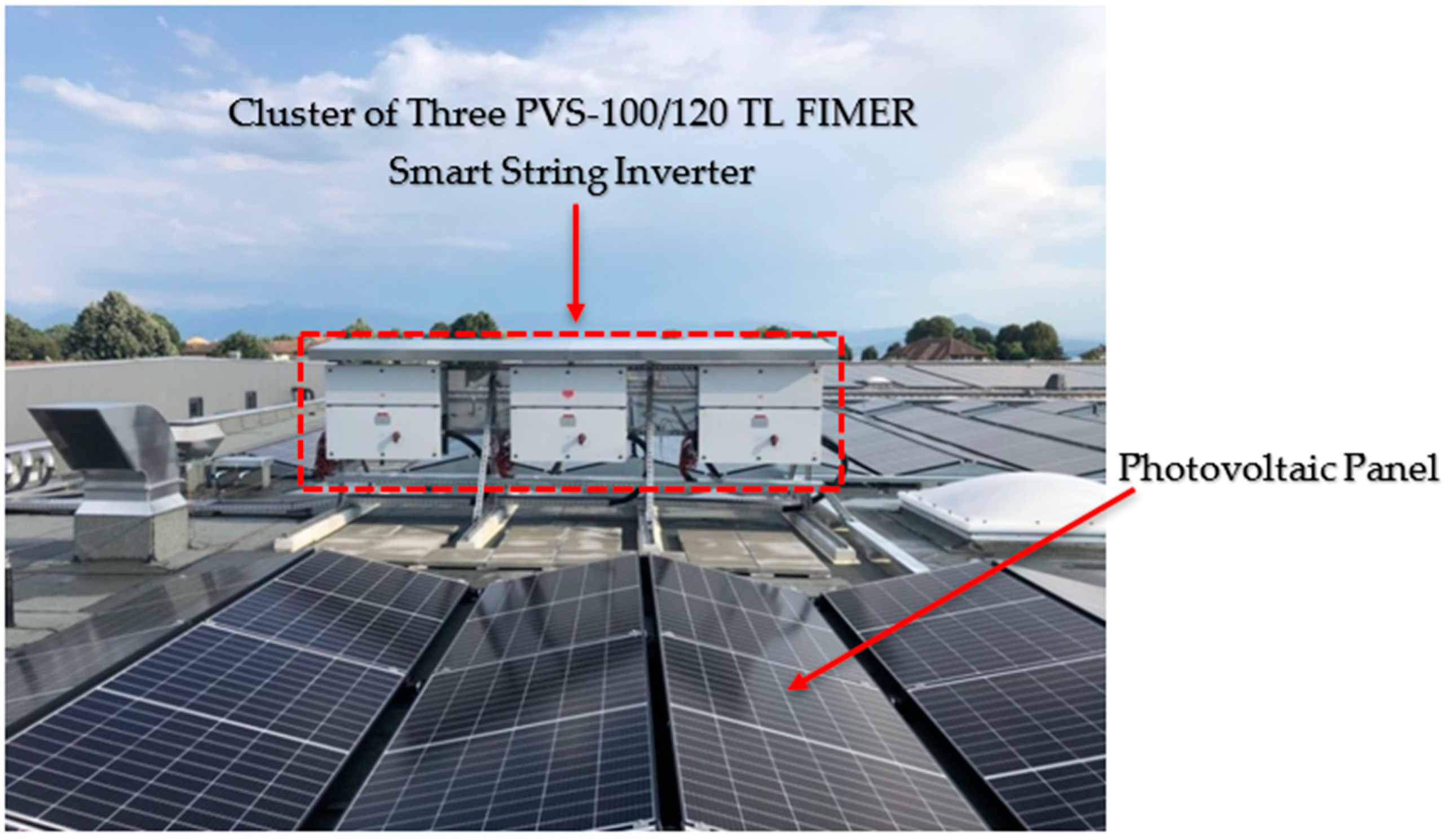
In this context, now more than ever, PV plants feature several string inverters, i.e., clusters composed of several inverters. Clusters of string inverters represent a central component in PV plants of any size, in both residential and Commercial and Industrial (C&I) applications. In
Figure 1 we show an example of C&I application featuring a cluster of three PVS-100/120-TL FIMER smart string inverters installed between Geneva and Lausanne, Switzerland. Photo courtesy of KDISOLAR (Nantes, France) [
9].
In modern-day Smart Grid’s context, the group communication model proves to be a suitable and effective paradigm to design and implement applications and services. In particular, in PV plants the group communication naturally supports and promotes in-network processing. This is a fundamental technique for elaborating the wealth of data provided by the cluster of inverters. According to this model, inverters cooperate towards a given cluster application by exchanging multicast messages.
A relevant example of PV systems application is export limiting. Distribution Network Operators (DNOs) set limits to the amount of power that a cluster of inverters can export to the grid at any time to guarantee grid stability. Therefore, inverters in the cluster must tightly cooperate so that the amount of energy they collectively produce does not violate the export limits. Every inverter periodically multicasts its own sun exposure and the amount of power it has currently exported to the grid. Furthermore, upon receiving these data from all the other inverters in the cluster, the inverter computes the amount of power that it is allowed to generate.
In order to effectively deploy PV systems, the need of secure multicast communication is of paramount importance. Clusters of string inverters may communicate through both wireless and wired networks. In the former case, an attacker equipped with a radio transceiver can easily get access to the cluster communications. In the latter case, you must consider that PV clusters are often installed in unattended geographical areas. Thus, an attacker has a simplified task to connect to the cluster even though it is wired. If an attacker succeeds in connecting to the cluster, (s) he can eavesdrop the network traffic, violating the confidentiality of the information flowing through the network, and inject false data or modify correct data, deviating the cluster’s behavior. Therefore, it must be guaranteed that only authorized principals are allowed to take part in the group communication. Unfortunately, clusters of string inverters currently use multicast over the User Datagram Protocol/Internet Protocol (UDP/IP), which does not provide any mechanism to restrict the access to transmitted data packets to cluster members only [
10].
A security infringement may cause both a confidentiality infringement and system misbehavior. An attacker that succeeds in eavesdropping the data traffic within the PV cluster becomes able to know the power generated by each inverter and so reconstructs the exported power profile of the overall PV plant. However, this is typically confidential information that should be known only to the owner of the PV plant. Furthermore, an attacker that succeeds in altering or injecting fake data becomes able to cheat the cluster into exporting no energy into the grid (zero energy attack) [
11,
12]. At the grid level, this attack causes an energy deficit that must be provided by means of conventional energy sources (e.g., burning oil or coke) so causing additional operational and environmental costs. The attack is even more disruptive at the microgrid level because it may cause a blackout with possible severe human and economic consequences. Alternatively, an attack can cause the cluster of string inverters to export more energy into the grid (energy overflow attack) than the limit set by DNOs. Both at the grid and microgrid level, the attack can trigger grid instability and damage sensitive loads attached on the grid or microgrid itself.
Reasons behind cyber-attacks may disparate and are associated with social, political, economic and cultural conflicts [
13]. As to economic reasons, a malicious service provider might want to unfairly gather confidential information about a competitor by an eavesdropping attack. Or, it may attack a competitor reputation by causing a misbehavior in the PV cluster. Other reasons to destroy or spoil a system include terrorism, vandalism, aimless exhibition of strength and intellectual unscrupulousness and eclecticism [
14].
Hence, if we wish to exploit the advantages of the group communication model, it is crucial to protect communication within the group. A primary method of limiting access to multicast information is through encryption and selective distribution of the secret cryptographic key (i.e., the group key) used to encrypt and decrypt group information [
15]. As a prudent cryptographic engineering practice, the group key should be periodically refreshed to prevent a passive attacker from collecting enough encrypted material to mount an analytical attack [
16,
17,
18]. When a new inverter joins the group, e.g., to increase the PV plant’s capacity, the inverter must be allowed to access the group communication. To achieve this, the joining inverter must be provided with the current group key. In contrast, when an inverter leaves the group because its mission is over, or it is forced to leave because it is suspected to be compromised or faulty, the inverter must be prevented from accessing any further group communication (forward security) [
19]. This requirement can be fulfilled by rekeying the group, that is by generating and securely distributing a new group key to group inverters but the leaving ones. It follows that key revocation has the same level of importance as key distribution. In fact, compromised string inverters must be logically removed from the network communication and, usually, the ability to logically remove them translates into the ability to revoke keys [
20,
21]. If cryptographic algorithms do not expose the secret keys, then they can only be compromised by compromising the device itself. It follows that by revoking all keys of a compromised device, it is possible to remove the logical presence of that device from the network.
In this paper we present a secure and efficient group Key Management System (KMS) to protect the group communication in a PV plant. The novelty of this work is twofold. First, research works do not consider the issue of secure multicast in clusters of solar inverters [
22,
23,
24,
25,
26,
27,
28,
29,
30,
31,
32,
33]. To the best of our knowledge, we are the first tackling the topic of secure group communication, and the related group key management, in the context of PV plants. Secondly, many group key management systems have been proposed [
34,
35,
36,
37,
38,
39,
40,
41,
42,
43,
44,
45,
46,
47,
48,
49,
50,
51,
52,
53,
54,
55,
56,
57,
58,
59,
60]. In this paper we prove that a point-to-point public key-based approach to group key management is a simple yet effective solution to guarantee performance and scalability requirements of a real cluster setup.
The KMS supports group key generation, rekeying, refreshing and distribution. During an initialization phase, the KMS initializes inverters in the cluster with the group key and forms the initial group membership. Upon an inverter’s leaving, the KMS generates a new group key and securely distributes to group members but the leaving one (i.e., rekeying). Furthermore, upon an inverter joining, the KMS securely transmits the current group key to the joining inverter. Secure distribution of the group key takes place through point-to-point secure Transport Layer Security channels [
61] wherein mutual authentication is enabled. Finally, the KMS periodically refreshes the group key by securely multicasting a newly generated group key (i.e., refreshing). The multicast message containing the refreshed group key is protected by means of an Encrypt-then-Message Authentication Code (MAC; EtM) authenticated encrypted scheme [
62]. The resulting multicast communication system is secure as only authorized inverters can take part in the cluster communications. Upon a leave event, the leaving inverter’s keys are revoked, so logically evicting the inverter from the cluster.
The Key Management System is architecturally organized in two main components: Key Distribution Supervisor (KDS) and Key Distribution Centre (KDC). The KDS resides in the cloud, in the case of Internet-connected clusters, or runs on a mobile device as a mobile application, in the case of Internet-disconnected clusters, which is operated by a trustworthy operator who physically goes to the cluster. An instance of the KDC is resident on every inverter in the cluster. At the moment of executing a join, leave or refresh operation, the KDS selects a KDC instance according to a certain policy and triggers the execution of the operation to that KDC instance, which coordinates the actual execution of the operation itself.
We experimentally show that our solution scales up to clusters of tens of inverters and displays a limited memory footprint so that it can be easily accommodated in memory-constrained devices. As a case study, we have built a prototype for a cluster of Power-One Italy S.p.A., a member of the FIMER Group, leader in the market of smart string inverters, under to following constraints: (i) the cluster must accommodate up to 50 inverters (notice that currently real cluster setups come with 40 inverters at most); (ii) the maximum rekeying time must be smaller than 60 s (s) and, finally, (iii) the available memory is 512 MBytes (MB). The proposed KMS turns out able to rekey 50 inverters in about 5.7 s, i.e., 9.5% of the maximum rekeying time, using an RSA-3072 cryptosystem. We also show that the public key cryptosystem has a relevant impact on the rekeying time and thus the overall scalability. In particular we show that, with an equal security level, 256-bit Elliptic Curves make it possible to halve the rekeying time. Furthermore, we show that the KMS displays a virtual memory footprint of about 5 MB, i.e., 1% of the available memory.
The rest of this paper is structured as follows. In
Section 2 we discuss related work. In
Section 3 we define the system model. In
Section 4 we describe the group key management scheme. In
Section 5 we evaluate the performance of the scheme. In
Section 6 we comprehensively discuss the scheme and provide a security analysis. Finally, in
Section 7, we draw our concluding remarks.
2. Related Works
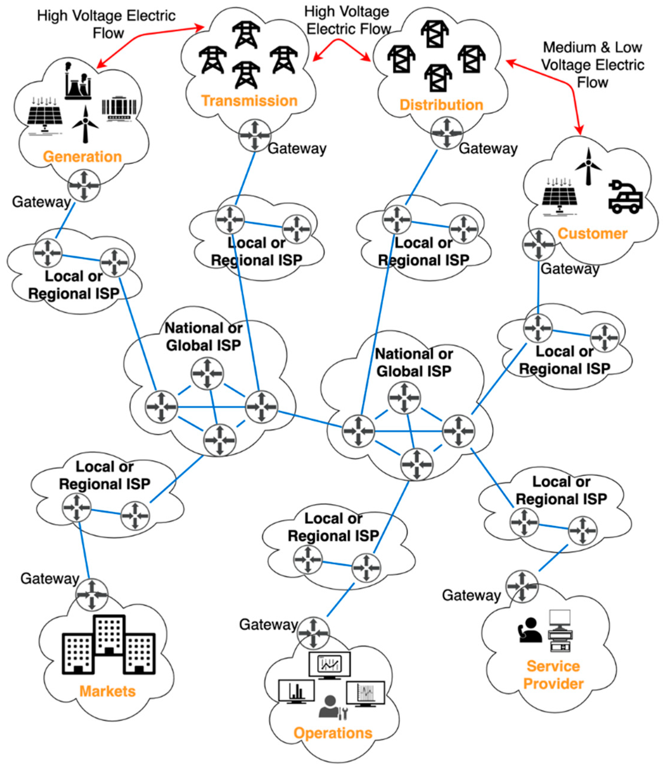
According to the National Institute of Standard and Technology (NIST), the architecture of the Smart Grid (SG) consists of seven domains each of which offers specific Smart Grid’s services [
63]. The seven domains are:
Generation: the electricity generators, including both traditional energy sources and distributed RES;
Transmission: the mediums of bulk electricity over long distances;
Distribution: the distributors of electricity to and from customers;
Customer: the energy consumers. However, they can also generate electricity. We differentiate between three types of customers: residential, commercial and industrial (C&I);
Markets: the operators and the players in electricity markets;
Service Provider: the entities offering services to customers;
Operations: the handlers of the energy flow.
To offer SG’s intendent services, in addition to energy generation, transportation and consumption, communication is required both within devices of the same domain, so-called intradomain communication, and between devices of different domains, i.e., interdomain communication. Communication consists of data packets exchanged via a network of communication links and routers, namely the Internet. In
Figure 2 we present the SG architecture together with the supporting Internet network infrastructure. We differentiated between energy flow (red lines) and data flow (blue lines).
In this SG’s context, IP multicast, i.e., the means of sending IP data packets from one sender to a group of intended recipients, has been recognized to have a variety of applications, including but not limited to monitoring, protection and information dissemination [
64,
65].
However, existing schemes for secure multicast communication in the Smart Grid only focus on the interactions between grid’s control centers and smart devices installed at customers’ premises. Aouini et al. present an IPSECurity-based (IPSEC) protocol to protect the multicast traffic between energy utilities control centers and a group of customer’s smart meters [
22]. The protocol consists of a group key management scheme and allows authentication of the smart meters. The IPSECurity-based protocol avoids eavesdropping, data injection and replay attacks. In [
23], both a mutual authentication scheme between customers’ smart meters and a Smart Grid’s security associate server and a key management protocol is discussed. In this respect, a key-pair, similar to the private–public key pair, is proposed. One key is for the group source, i.e., the Smart Grid’s security associate server. This is called Multicast-Source-Key (MSK). The second key is known as Multicast-Receiver-Key (MRK) and is for group receivers, i.e., smart meters. Whenever the Smart Grid’s security associate server wants to send information to the smart meters, it uses the MSK to encrypt multicast packets. On the other side, group receivers use MRK to decrypt the packets. The scheme also foresees refresh of the group key. Nicanfar et al. [
24] describe a multicast scheme that mutually authenticates a customer’s smart meter and an authentication server in the Smart Grid. Authentication takes place through an initial password. Then, the authors describe a key management protocol based on enhanced identity-based cryptography. The scheme exploits the public key infrastructure. The scheme also embeds a key update process to provide both backward and forward secrecy and to preserve the group key secrecy over time. In [
25], a secure multicast routing protocol is proposed. During an initial authentication phase, the protocol registers a group of customers’ smart meters with an access point acting as certificate authority. After that, a communication phase follows. This consists of individual SMs securely sending data to the grid’s operation centers and the latter securely sending, occasionally, control messages to the multicast group. Saxena et al. [
26] propose a multicast communication scheme based on a publisher–subscribers architecture. The publisher is a Smart Grid’s Human Machine Interface/Supervisory Control And Data Acquisition (HMI/SCADA) server (e.g., a phasor gateway) whereas the subscribers are customer’s intelligent electronic devices (e.g., circuit breakers, transformers and capacitor banks). The scheme ensures mutual authentication between publisher and subscribers and secure delivery of multicast information.
Kim et al. [
29] propose a tree-based key management scheme for secure unicast, multicast and broadcast communication in a Smart Grid network with millions of entities (e.g., Smart Grid facilities, smart meters and sensors). The protocol is based and extends a key management protocol for secure broadcast communications in pay-TV broadcasting systems [
31]. The scheme is secure against three types of threats: (a) loss of confidentiality; (b) loss of integrity and (c) loss of availability. Long et al. [
32] present a key management scheme for secure unicast, multicast and broadcast communication among various components in the Smart Grid, namely power grid control systems and remote sensors and meters. The proposed scheme employs the Iolus framework [
45] for structured key management. The scheme supports the hierarchical structure of the Smart Grid’s control mechanism, i.e., from top to the bottom: control centers, regional coordinators and remote end customers’ devices. For this reason, the scheme provides two different key management mechanisms for upper and lower level communications. This is according to the different resource limits at two different levels. Benmalek et al. [
33] focus on the security of the Advanced Metering Infrastructure (AMI) because of its critical role for the security of the Smart Grid. AMI is responsible for two main tasks. On the one hand, to collect time-based data from consumer’s smart meters and transmit them to AMI host systems. On the other hand, it is also responsible for implementing control commands from AMI host systems to customer’s smart meters, so as to perform required control actions (e.g., mechanism that enable customers to cut down energy usage at peak times). In their paper, the authors propose a Multi-group Key management for AMI (MK-AMI) that support unicast, multicast and broadcast communications. The scheme guarantees: (i) confidentiality of customer’s sensitive data; (ii) integrity of data (e.g., information and control commands) transmitted from customer’s smart meters to AMI host systems and vice versa; (iii) data availability and (iv) non-repudiation. From the performance evaluation viewpoint, the authors show that MK-AMI achieves low storage and communication overheads.
Summarizing, existing related works for secure group communication in the Smart Grid only focus on the intercommunication between Smart Grid’s Operations and Customer domains. In this work, instead, we rather focused on the intracommunication among specific devices of the Customer domain, namely clusters of smart string inverters. To the best of authors’ knowledge, we are the first facing the topic of secure group communication within the context of PV installations.
3. System Model
With reference to
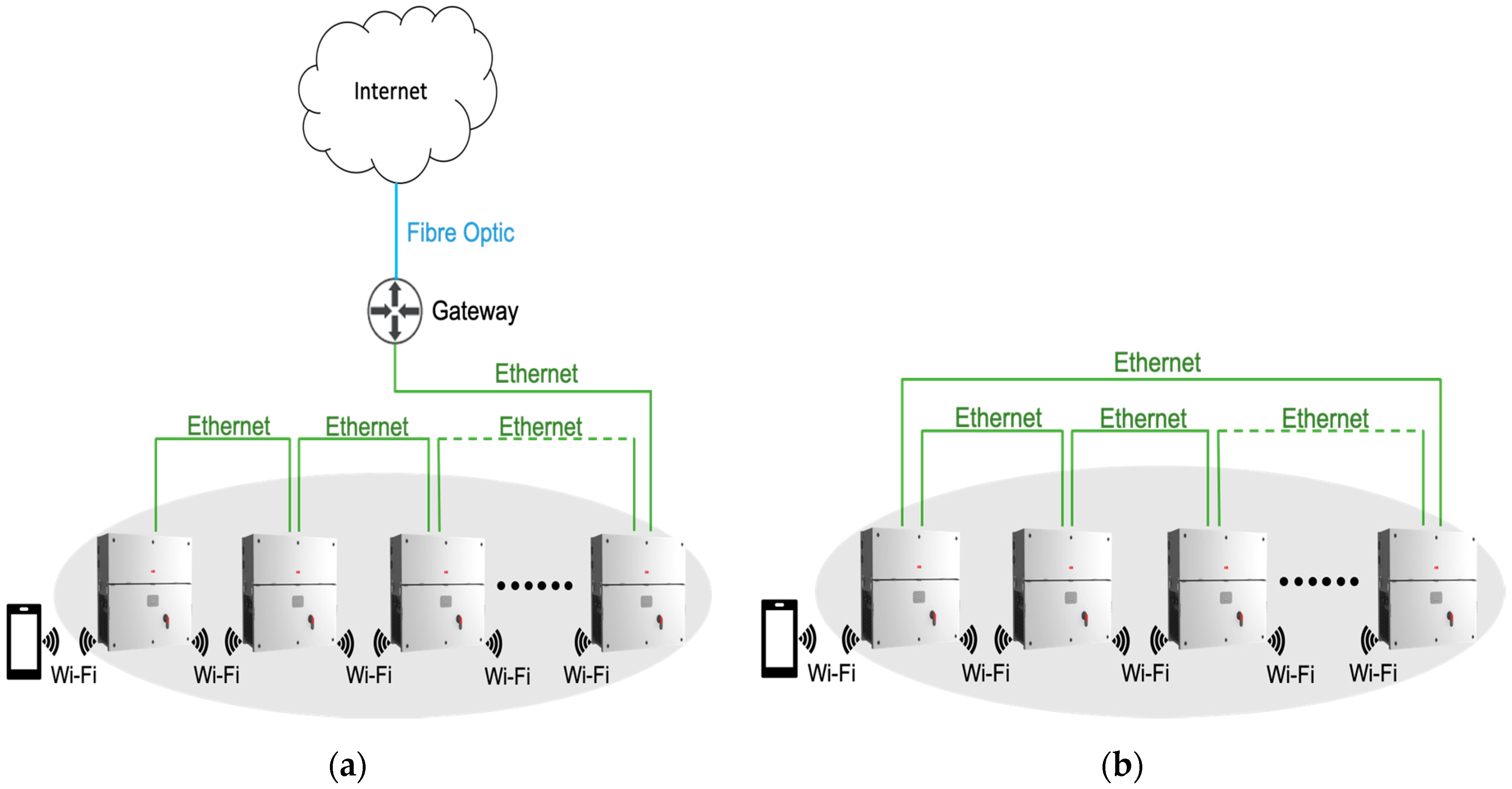
Figure 3, we considered a cluster of
n inverters interconnected by a communication link, both wired (e.g., Ethernet) or wireless (e.g., WiFi). The cluster may be both Internet-connected or not. Inverter
i, 1 ≤
i ≤
n, is identified by a unique identifier UID
i and is configured with a pair of public-private cryptographic keys (
privKi,
pubKi). Let Cert
i be the certificate released to inverter
i by a Certification Authority (CA) trusted by all inverters in the cluster. Certificate Cert
i as well the root certificate Cert
CA of the Certification Authority CA are locally stored at any inverter
i. Furthermore, we assumed that each inverter maintains a Certificate Revocation List (CRL) whereby it stores revoked certificates. Every inverter is equipped with a hardware secure module (HSM) to store secret cryptographic material (e.g., the private key) and a Cryptographically Secure Pseudo Random Generator (CSPRG) [
66]. We assumed that by exploiting the public key material, any pair of inverters could securely communicate in a unicast fashion. By secure we mean that the unicast channel guarantees data confidentiality, integrity and authenticity and inverters’ mutual authentication. On the point-to-point channel, an inverter will abort any attempts of communication from other inverters whose certificates are present in its own CRL. This allows only authorized inverters to securely communicate in a unicast fashion with each other. To fix ideas, you may assume that a pair of inverters uses the Transport Layer Security (TLS) to establish a secure channel whereby mutual authentication (mTLS) has been activated. TLS connection establishment is aborted if the other inverter’s certificate has been revoked. The security of the TLS protocol has been extensively scrutinized [
67,
68,
69,
70,
71]. Protocol and implementation vulnerabilities afflicted different versions of TLS [
72,
73,
74]. In this paper, we assumed an implementation of TLS, which did not suffer from any known vulnerability.
Inverters of the cluster form an IP multicast group
G. To limit access to multicast information, group members share a secret cryptographic key, the group key, which they use to encrypt and decrypt messages that are transmitted and received, respectively, within the group. We denoted by K
G the group key of group
G. We employed the Galois Counter Encryption Mode (GCM) to meet the confidentiality, integrity and authenticity of group communication [
75].
An inverter becomes a member of the group by explicitly joining it. We call this operation join. Upon joining the group, the new member receives the current group key. As a member of the group, an inverter may multicast messages to the other group members.
Later, a member may leave the group. We call this operation leave. Leaving the group may be voluntary, e.g., when the inverter’s mission is completed or when the inverter is sent to maintenance. Alternatively, an inverter may be forced to leave because compromised or suspected to be so. When an inverter leaves the group, the current group key is revoked and a new one is distributed.
In addition, the group key is periodically renewed. We call this operation key refresh.
The group of inverters is managed by a Group Controller (GC) that is composed of three main services: a Group Membership Service (GMS), a Key Management Service (KMS) and an Intrusion Detection Service (IDS).
The GMS component maintains the membership of the group by keeping track of inverters that join and leave the group. Upon a membership change, GMS invokes the join or leave operation accordingly.
The IDS probes/monitors the network activities to uncover compromised inverters. Upon detecting a compromised inverter, the IDS forces the inverter to leave the group by reporting the inverter’s identifier to the GMS.
Whenever an inverter joins, the current group key must be distributed to joining inverters. Whenever an inverter leaves, or is forced to leave the group, a new group-key has to be generated and distributed to group members but leaving ones in order to guarantee the forward security requirement. KMS is the component responsible to perform such tasks. KDS also features a group key refresh to reduce the amount of encrypted material for an effective analytical attack. Both during a leave and a key refresh operation, the KDC generates the new group key in a cryptographically secure random way.
In this paper we focused on KMS and did not treat IDS and GMS any further. The interested reader may find initial readings about IDS and GMS in [
76,
77,
78,
79]. In
Table 1 we introduced key notations.
4. The Group Key Management Scheme
Before deep diving into the details of the group key management scheme, it is important to outline the advantages and disadvantages of a KMS in comparison to other methods. Specifically, we made the comparison with a preshared key, i.e., a shared long-term secret. We assumed this long-term secret to be shared among inverters in each cluster and used to encrypt the group communication.
Table 2 summarizes advantages and disadvantages of each method.
A KMS deals with the generation, storage, exchange, use and replacement of cryptographic keys. With respect to our use case, cryptographic keys were used to encrypt the group communication. On the other hand, a preshared key only requires to be shared through a secure channel before being used to encrypt the group communication. In this regard, we could assume inverters in the same cluster to be configured with such a long-term secret beforehand (e.g., a time of manufacturing). Therefore, we could state the complexity of a KMS was higher than the complexity of establishing a preshared key.
Regarding security, the main difference between the two approaches is that as soon as the preshared secret gets compromised all future multicast messages can be deciphered (and previous ones, if they have been recorded). Actually, this also holds in case of a KMS. Nevertheless, a KMS allows for replacement of the (compromised) cryptographic key and generation of a new one. Assuming a secure channel to distribute the newly generated key, we can state that the security of the group communication is higher in case of a KMS.
As to performance, with respect to our use case, a KMS requires group key generation, storage, distribution and replacement over time. Based on the specific cryptosystem involved, all these operations have an impact, more or less prominent, in terms of performance of the resulting scheme. In any case, such performance will always be lower with respect to an already established preshared key. Securing the multicast communication is the primary goal of this work, thus the reason behind the choice of a KMS.
We now described the join, leave and key refresh operations performed by the KMS. As mentioned in
Section 1, from an architectural point of view, the KMS comprises two components: a Key Distribution Supervisor and a Key Distribution Centre.
An instance of the KDC resides on every inverter in the cluster. Regarding the KDS, in the case of Internet-connected clusters, it runs on the cloud as a cloud application. In contrast, in the case of Internet-disconnected clusters, the KDS runs on a mobile device as a mobile application. The mobile app is used by a trustworthy operator who physically goes to the cluster. We assumed that the KDS is equipped with a pair of private and public key, along with the related certificate, and thus can securely communicate in unicast fashion with any instance of the KDC residing on any inverter in the cluster.
Upon handling a change in the group membership, the GMS notifies the KDS about the kind of event, join or leave, that gives rise to the membership change. Consequently, the KDS triggers the execution of the join or leave operation to an instance of the KDC. The KDS also gives support to a periodic refresh aimed at reducing the amount of encrypted material available to an adversary. So, the KDC triggers the execution of key refresh operations too. Once triggered, the specific instance of the KDC coordinates the actual execution of the operation. The KDS exploits a given policy (e.g., highest/lowest UID) to select the instance, i.e., the inverter where the instance is resident.
In the initialization phase, KMS initializes inverters that form the initial membership. Such initialization takes place via offline methods. KMS assigns each group inverter i the unique identifier UIDi, the public–private key pair (privKi, pubKi), along with the corresponding certificates Certi and CertCA, and an empty CRLi (i.e., with no revoked certificates). Finally, KMS generates the initial group key KG and initializes each inverter with that key. Inverters store the group key and their respective private key in the hardware security module HSM.
The following description of the operations concerns the steady-state, i.e., the state in which all involved group members are up and running.
For the sake of brevity, in the following subsections we will say that “a principal A securely unicast a message m to a principal B” meaning that a secure channel (i.e., a TLS connection) between principals A and B has been successfully established and message m has been sent by A to B through it.
4.1. The Join Operation
Let us consider the situation in which KG is the current group key and a set of inverters has to join the group. We called the Joining Set that set and denoted it as JS. The join operation consists of the following steps.
Initially, the KDS selects a KDC and securely sends it a ‹Join, JS› message that specifies the Joining Set JS.
Upon receiving the ‹Join, JS› message, the KDC reads a timestamp τ from its clock and securely unicasts every inverter in the joining set JS a ‹SeTKey, τ, KG› message specifying the current group key KG. Upon receiving a ‹SeTKey, τ, KG› message from the KDC, a joining inverter takes the following actions:
Check the freshness of timestamp τ (if the timestamp is not fresh, the protocol is aborted);
Securely store key KG into the hardware security module HSM;
Install KG as the current group key.
Finally, the KDC replies to the KDS that the join operation has completed.
At the end of the protocol, all inverters in the group, comprising the ones just joined, can communicate using the group key KG.
4.2. The Leave Operation
Let us consider the situation in which KG is the current group key and a set of inverters has to leave the group. We call the Leaving Set that set and denoted it as LS. Since inverters are leaving the group, the CA revokes the certificates issued to each inverter in LS. The CA also updates the CRL with revoked certificates’ serial numbers. The leave operation consists of the following step.
The KDS selects a KDC and securely sends it a ‹Leave, LS, CRL› message specifying the leaving set LS and the updated CRL.
Upon receiving the ‹Leave, LS, CRL› message, the KDC reads a timestamp τ from its clock, randomly generates a new random group key K′G, and securely sends a ‹SetKey, τ, LS, CRL, K′G› message to every inverter in the cluster but those belonging to LS. This means to any inverter i G \LS where symbol ‘\’ denotes the set difference operator. Upon receiving the ‹SetKey, τ, LS, CRL, K′G› message from the KDC, an inverter i takes the following actions:
Check the freshness of timestamp τ (if the timestamp is not fresh, the protocol is aborted);
Store the updated CRLi CRL;
Securely store the key K′G in the hardware security module HSMi;
Assume key K′G as the current group key.
Finally, the KDC replies to the KDS that the leave operation has completed.
At the end of the protocol, all inverters in the group G but the leaving one can communicate using the group key K′G.
The leave operation logically evicts a leaving inverter from the group by preventing it from communicating after the leave operation has completed. This eviction must be performed at two layers: at the application layer, by revoking the current group key and redistributing the new one to every inverter but the leaving one (step 2.c); and at the transport layer, by updating the certificate revocation list (step 2.b).
4.3. The Key Refresh Operation
Let us consider the situation in which KG is the current group key, which has to be refreshed. The refresh operation consists of the following steps.
The KDS selects a KDC and securely sends it a ‹Refresh› message.
Upon receiving the ‹Refresh› message, the KDC reads a timestamp τ from its clock, randomly generates a new random group key K′G, and securely multicast a message ‹SetKey, IV, › in its encrypted and authenticated form under the current group key KG to every inverter in the cluster. The notation indicates a keyed hash function, namely a Message Authentication Code (MAC) whereas IV denotes an initialization vector, i.e., a nonce. Upon receiving the ‹SetKey, IV, › multicast message from the KDC, an inverter i takes the following actions:
Compute the MAC applying on the encrypted part of the message, , and compare it with the MAC contained in the message (if the MACs do not match, the protocol is aborted);
Decrypt the encrypted part of the message, , by means of the current group key KG and the nonce IV;
Check the freshness of timestamp τ (if the timestamp is not fresh, the protocol is aborted);
Store key K′G in the hardware security module HSMi;
Install key K′G as the current group key.
Finally, the KDC replies to the KDS that the refresh operation has completed.
At the end of the protocol, all inverters in the group G can communicate using the new group key K′G.
5. Performance Evaluation
5.1. Experiment Settings
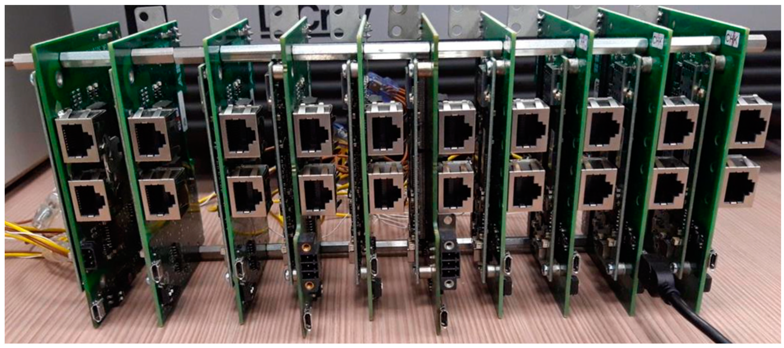
In order to demonstrate the feasibility of the proposed key management scheme, we built a prototype in the C++11 programming language and deployed it on a cluster composed of ten Power-One Italy S.p.A. inverters. The entire cluster is powered with the following voltages/currents: (a) +12 volts (1.5 ampere) and (b) +3.3 volts (0.5 ampere) by means of a 450-watt Allied switching power supply unit (model AL-B450E).
Each smart string inverter in the cluster was equipped with 512 MB Double Data Rate 3 Low voltage (DDR3L) of Random Access Memory (RAM; at 400 megahertz), an Advanced Risk Machine (ARM) Cortex-A8 (model AM3354BZCZA100) Central Processing Unit (CPU) @1.0 GHz, and 4 GBytes (GB) embedded MultiMediaCard (eMMC) flash storage. Cluster inverters run 32-bit Ubuntu 14.04.4, desktop version.
Figure 4 shows the cluster.
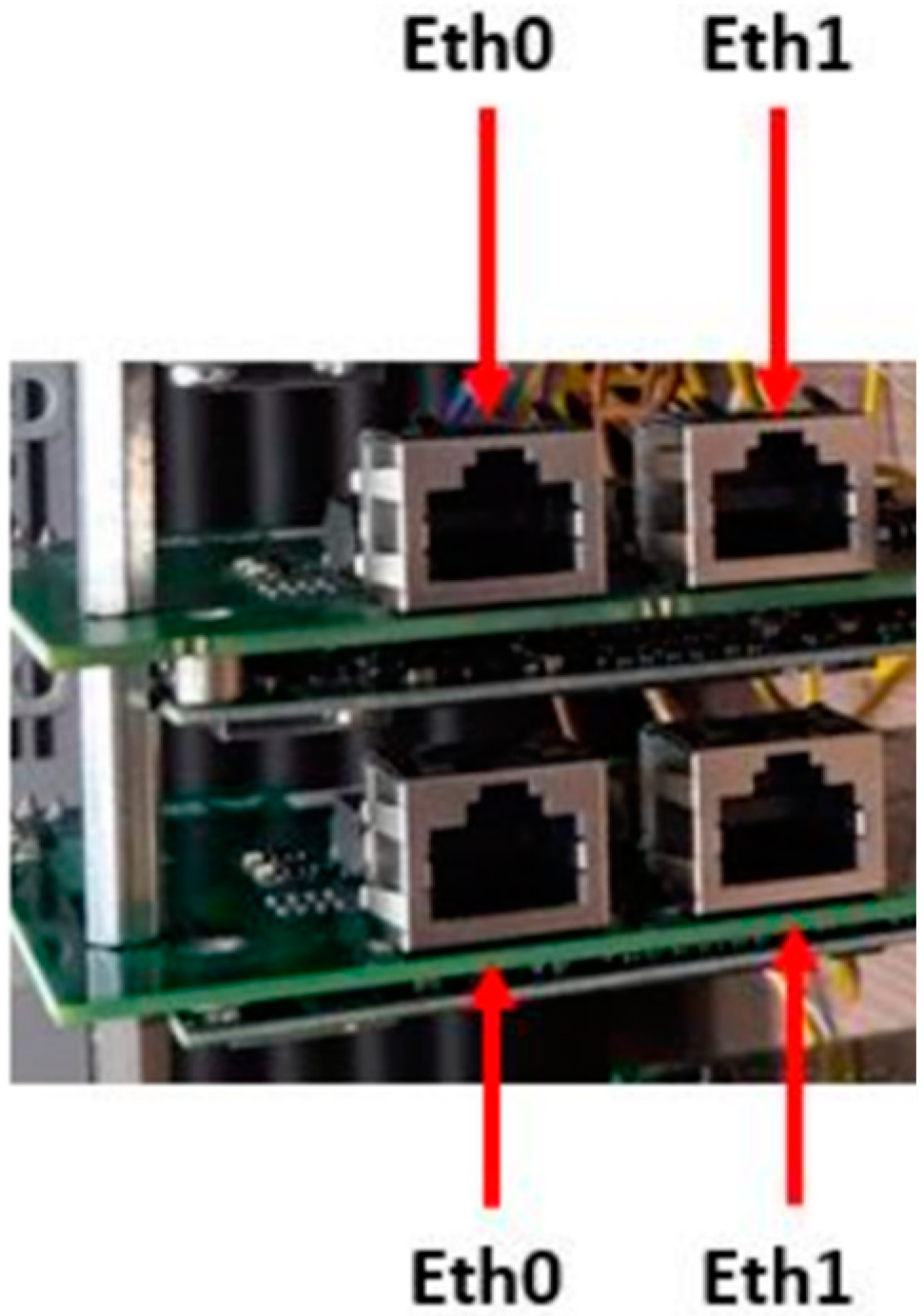
Cluster inverters are interconnected by an Ethernet-based LAN in the daisy chain topology. For this purpose, the key elements are the two Ethernet interfaces 10/100BASE-T, namely Eth0 and Eth1. Specifically, interface Eth0 of one inverter is connected via an Ethernet cable to interface Eth1 of the next inverter and so on and so forth.
Figure 5 shows the system setup’s main connections.
Due to Power-One Italy S.p.A. guidelines and recommendations, including the ones on cybersecurity, a minimum-security level of 112-bit should be considered. Effectively, we considered 112-bit and 128-bit security levels, in the event of future development. Therefore, we endowed each cluster inverter both with an RSA and Elliptic Curves (ECs) private–public key pair with 112-bit and 128-bit security level.
Table 3 presents the mapping between the security level and corresponding type/length of endowed cryptographic keys.
In other terms, the RSA keys length was 2048-bit and 3072-bit while EC named curves considered were secp224r1 (equivalent to 2048-bit RSA key) and secp256k1 (equivalent to 3072-bit RSA key). On the other hand, we always considered a 128-bit long (i.e., 16 bytes) symmetric group key. This was used with Advanced Encryption Standard in Galois Counter Mode (AES-GCM).
Each of the four public keys was certified by an (X509v.3) certificate. Each certificate was issued by an (offline) root Certification Authority (CA) that we created ad-hoc. Certificates were issued from the root CA upon processing associated CSRs. Finally, we also saved the (self-signed) root CA certificate and the CRL on each inverter. In other terms, we defined a one-tier Public Key Infrastructure (PKI) hierarchy chain, with the single CA acting as both root CA and issuing CA.
The reason why we endowed each inverter with different types of keys of a different key length was to evaluate the performance of the scheme as a function of those. Particularly, we evaluated the performance of the prototype along two dimensions, namely: (i) latency for group key generation and distribution and (ii) memory overhead.
5.2. Latency for Group Key Distribution
Latency of operations must comply with the typical timing constraints of a PV plant that are in the order of one minute (at the most). This is essentially a usability requirement engineered (particularly) when the KDS comes in the form of a mobile application. It represents the (maximum) time the operator is willing to wait in order for an operation to complete. The lower the latency the better it is.
We mainly focused on the performance of join and leave operations, which use public key cryptography to establish secure channels (i.e., TLS connections) to communicate the current/new group key to group members. The refresh operation instead multicasts the new group key in its encrypted form under the current group key. This operation uses symmetric encryption, which is much faster than public key encryption [
80].
We evaluated the latency to communicate with a number of group members using different cryptosystems. Specifically, we assumed the group size to range between a minimum of 10 and a maximum of 50 inverters and evaluate the scalability of the prototype as a function of the group size. The lower and the upper bound were due to Power-One Italy S.p.A. single PV plant’s typical capacity, around 2 MegaWatts (MW), and Power-One Italy S.p.A. maximum and minimum inverters’ nominal output power, namely 200 KW and 50 KW, respectively. Although the theoretical upper limit was 40 inverters, we considered 50 of them so as to offer a safe margin.
Practically, to evaluate latency, since the cluster at our disposal consisted of ten inverters only, we executed the prototype multiple times on each cluster inverter in a concurrent fashion, but the one selected as KDC. The different processes only differentiated by the port number associated with the TCP listening socket. Specifically, each cluster inverter but the KDC executed 2, 3, 4 or 5 processes for group size respectively of 20, 30, 40 or 50 inverters. Latency was computed as the time required to distribute the group key to required group members. For each group size considered: (i) have performed 40 experiments, each under the same conditions and (ii) we then double-checked that the latency values obtained by the experiments were independent and identically distributed (i.e., IID-ness hypothesis test). This was accomplished considering a 99% confidence level; (iii) finally, we computed the mean latency and the associated confidence interval. The conditions under which experiments were carried out are summarized here below:
The CRL is empty, i.e., it does not contain any revoked certificates;
Inverters’ mutual authentication;
The negotiated cipher-suite(s) consists of one and only one element (because each cipher suite takes 2 bytes in the ClientHello message), namely:
Parameters (i.e., p,g) related to the ECDH(E) key exchange have been pregenerated by one inverter and stored on each of the other cluster inverters;
The verification of the inverter certificates’ digital signature consists of one and only one verification. This is according to the defined PKI hierarchy chain. Signature’s verification is carried out using the public key of the root CA;
Session caching not enabled.
Experimental results were pretty much the same, with the latency in case of a leave operation a bit higher due to the generation of the new group key (and the time to store the updated CRL). Therefore, with respect to
Figure 6;
Figure 7, we considered a leave operation only. For this reason, a group size equal to some value “x” means that the cardinality of the set of remaining inverters, i.e., the ones to which distribute the newly generated key, is equal to “×”. Finally, it is important to remember that latency accounts for both computation and communication overheads.
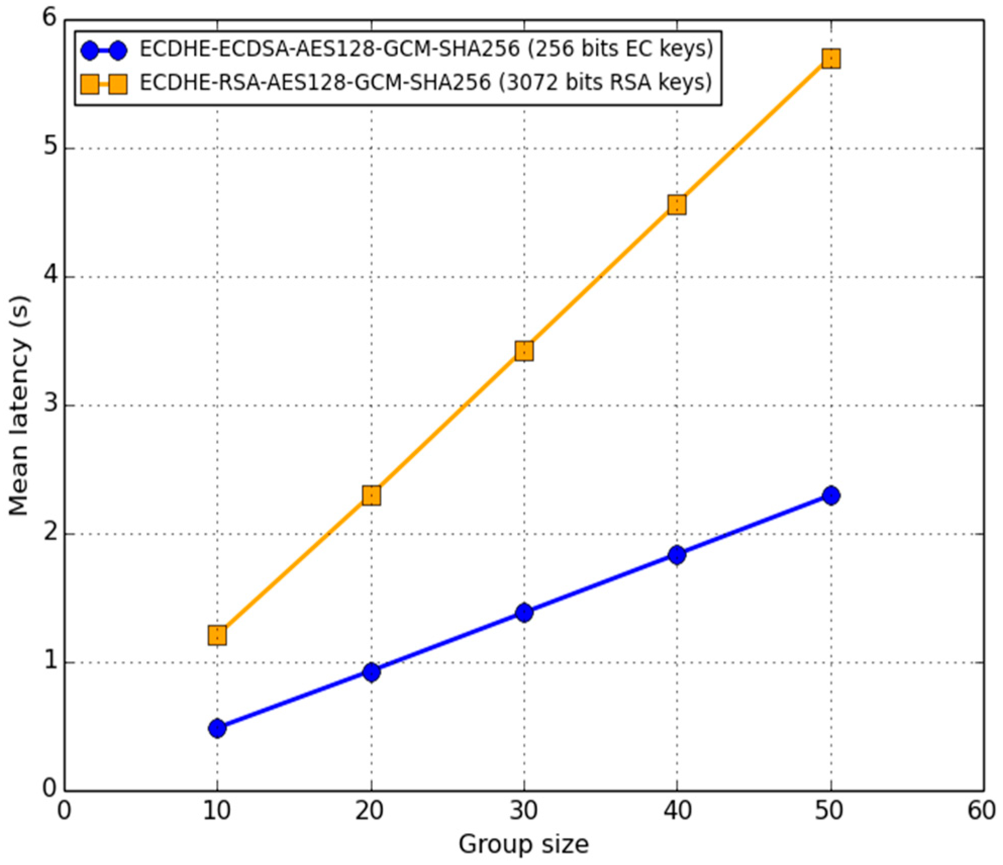
In
Figure 6, we present the (mean) latency (in seconds) of the prototype as a function of the group size and type/length of the key, specifically: RSA vs. EC keys with 128 bits security level. Confidence intervals are not shown due to the scale on the y-axis. The comparison experimental results in
Figure 6 show that typical PV plants’ timing constraints were definitely met. In general, the (mean) latency increased linearly with the group size. We demonstrated that we expected such behavior in our discussion in
Section 6.2. Furthermore, because of ECDSA’s faster processing times and the lower demands on bandwidth with respect to RSA [
81], latency in the case of EC keys is less than half the latency required in the case of RSA keys.
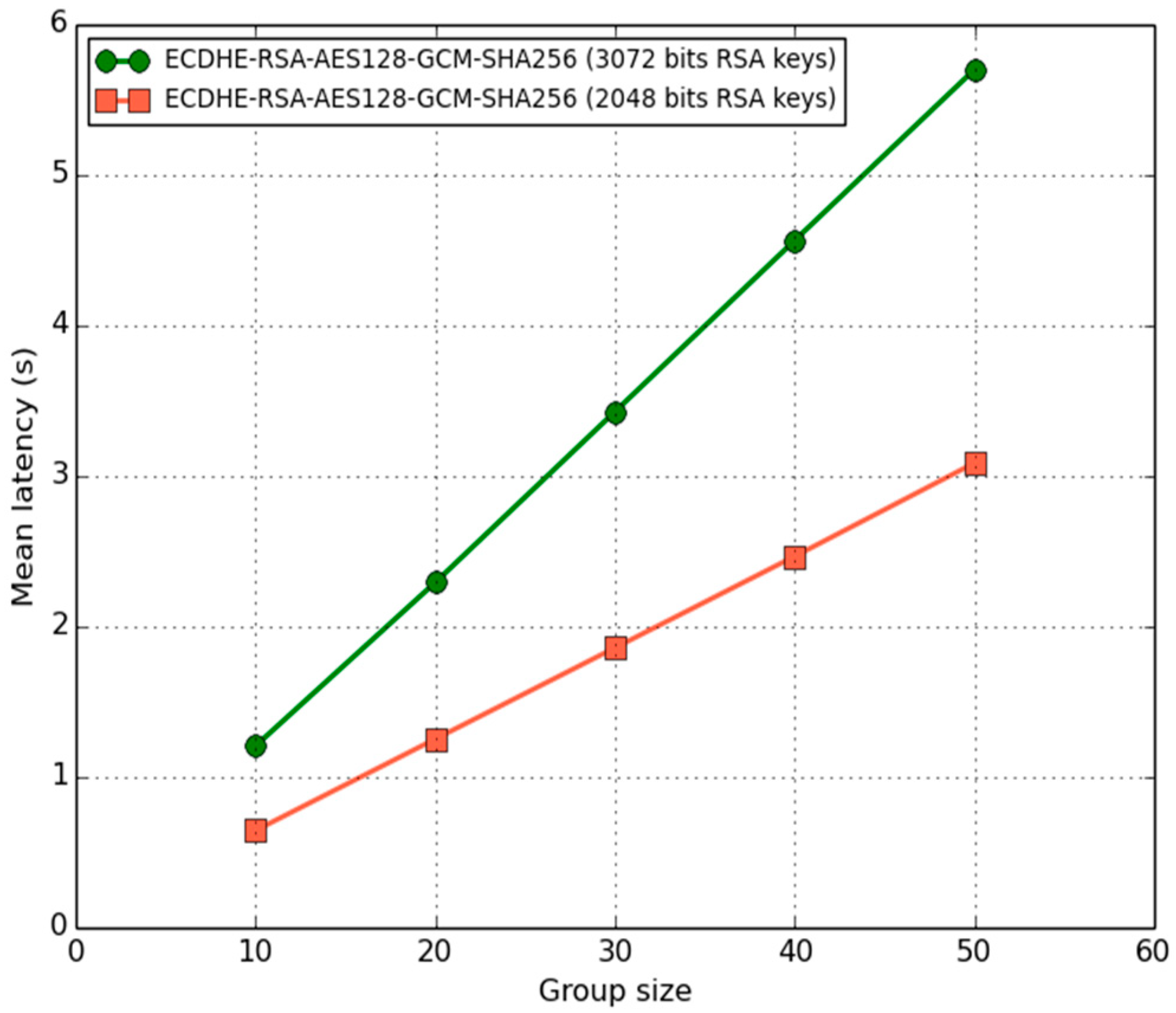
Due to the architecture of Power-One Italy S.p.A. developed inverters and under development, we then specifically focused on RSA keys only. In
Figure 7, we show the mean latency as a function of the group size and RSA key security levels considered: 112-bit vs. 128-bit.
As one might expect, the (mean) latency was approximately 83–87.5% higher in the case of 128-bit strength RSA keys. Though, in this case, the scheme only required 5.7 s to distribute a new group key to 50 inverters. This accounted only for 9.5% of the maximum time allowed for group key distribution, namely 60 s. Therefore, we evaluated the efficiency of the scheme. Specifically, we provided a first definition of efficiency according to the following equation:
It turns out that . It is worthwhile to notice that if the PKI hierarchy chain consisted of intermediate issuing CAs, rather than the root CA only, it would be necessary to verify the digital signatures on the certificate chain up to the root CA. This would increase the latency.
Last but not least, it is important to highlight that we evaluated the (mean) latency, reported in
Figure 6 and
Figure 7, for group sizes greater than 10 members by concurrently running more processes on inverters. As inverters were equipped with a single core CPU, the mean values shown above need to be considered as higher estimates.
In
Table 4 we present the main results regarding latency for group key distribution in a leave operation. As repeated throughout the paper, to the best of author’s knowledge, we are the first addressing the issue of secure group communication in clusters of smart string inverters. Consequently, the results presented below cannot be compared neither with the states of the arts nor with other peoples’ work.
5.3. Memory Overhead
As to memory overhead we intended the memory occupancy of the executable image of the prototype. Since smart string inverters are constrained devices, the lower the memory footprint the better it is.
In
Figure 8 we present the memory footprint of the prototype implementation. We still considered the case of a leave operation and the following cryptosystem: ECDHE-RSA-AES128-GCM-SHA256 (i.e., RSA keys). The security level considered was 128-bit whereas the group size was equal to the maximum cluster size (i.e., 50 inverters).
Memory usage was measured by means of the Unix-like process pseudo-file system, namely the proc (virtual) file system. Particularly, we gathered information from /proc/pid/status where pid was the process id of the prototype.
Figure 8 shows that the Virtual Memory Size (VmSize) of the prototype process was less than 15 MB (i.e., green plus brown rectangles). Of this, less than 5 MB is the maximum Resident Set Size (VMRSS), i.e., the amount actually resident in the main memory. Thus, as far as the VMRSS is concerned, we can state that it accounts (only) for less than 1% of the overall inverter main memory.
With respect to memory overhead, we defined efficiency according to this other equation:
Thus, the efficiency of the scheme in terms of memory overhead is:
. Since smart inverters are constrained devices this is quite an important result. Finally, in
Table 5 we summarized the main results of this subsection. Due to the lack of existing related research works, results could not be used to make comparisons.
6. Discussion
6.1. On the Join Operation
Unlike the leave and key refresh operations, the join operation is not conducive to the creation and installation of a new key, but it simply distributes the current one to the new group members. This allows us to make it computationally less burdensome than the other two operations.
Before successfully completing, a leave/key refresh operation has to make certain that all intended inverters receive the new group key. Otherwise, inverters could end up using different group keys, the old and the new one, so partitioning the group into two logically disconnected subgroups. If during the execution of a leave/refresh operation, an inverter becomes temporarily unavailable (e.g., because of a reduced sun exposure), the execution is aborted. Later, GMS will inform KDS when the inverter recovers. Then, GMS triggers a new execution of the operation. Of course, more complex solutions could be conceived whereby the execution is not aborted and the unavailable inverter gets updated later upon recovery. For the sake of system simplicity, we chose not to pursue this way, as intermittent availability events are infrequent and mostly brief (of course the KDS wisely avoids triggering a rekeying/refreshing operation in a cloudy day or when the dark is approaching).
In contrast, the join operation does not require the execution to abort. Actually, as soon as a joining inverter has performed step 2a and 2b, it may join the group and start sending multicast messages using the current group key.
6.2. On Contributory Group Key Generation
In our approach the KDS selects a given KDC instance, which generates and distributes the new group key. In an alternative contributory approach, all KDC instances contribute to the generation of the group key with their own share [
15].
Generating the group key in a contributory fashion is not suitable for our case because group members have to obtain the group key within a tight deadline, which is in the order of a minute. The issue with generating the group key in a contributory fashion is that, whatever operation we consider—join, leave or key refresh—the overall communication overhead grows linearly with the group size and thus is in the order of O(
N) [
15]. Due to the presence of a deadline, a contributory approach may not be feasible in a large group so limiting the scalability of the group itself.
Alternative contributory approaches are those tree-based (e.g., distributed one-way function tree and Diffie–Hellman logical key hierarchy) where the overhead results to be logarithmic in the group size, i.e., in the order of O(log
N) [
15]. However, better performance comes at the cost of increased complexity of the key management scheme. This is especially true in our application scenario where group members may be intermittently available due to reduced sun exposure. Therefore, for the sake of simplicity, we did not consider tree-based contributory approaches and we did not mention them any further.
We now analyzed the complexity of the scheme we proposed, in terms of overall communication overhead, and compared it with the complexity of a contributory approach.
Table 6 summarizes the results.
First, whatever the operation we considered, in the scheme we proposed the communication (and computation) overhead of involved group inverters but the KDC was always constant, i.e., O(1).
In the case of a join operation, the KDC unicasts the current group key to all joining inverters. It follows that the communication overhead of the KDC increased linearly with the number of joining inverters. If we indicate with nj = |JS| the cardinality of the set of joining inverters, then the communication overhead of the KDS is in the order O(nj). Therefore, the overall communication overhead is O(nj) + O(1) = O(nj). As mentioned above, in a contributory approach the overall communication overhead increased linearly with the total number N of group members. In general, O(N) >> O(nj), up to even one order of magnitude.
In the case of a leave operation, the KDC first generated a new group key and then securely distributed it to each non-evicted group member. So, the KDC had a communication overhead that increased linearly with the number of inverters that remained in the group. We called them the remaining inverters. Let LS be the set of leaving inverters, nl the cardinality of that set, RS = G\LS the set of remaining inverters and nr its cardinality with nr = |RS| = |G\LS| = N - nl. It follows that the communication overhead of the KDS is in the order of O(nr). Thus, the overall communication overhead is O(nr) + O(1) = O(nr). In the case of a contributory approach, the total communication overhead linearly increased with the group size and, for this reason, it was equivalent to our approach, i.e., O(N) = O(nr).
Finally, in the case of the refresh operation, the total communication overhead corresponded to the communication overhead of the KDC only. The overhead amounted to a single multicast message, hence was constant, i.e., O(1).
6.3. Security Analysis
In this section, we considered the security of the join, leave and key refresh operation with respect to two kinds of attacker, the external attacker and the evicted inverter. An external attacker shares no secret with the cluster. In contrast, an evicted inverter holds one or more group keys it obtained when it was a member of the group.
Regarding the external attacker, we claimed that the execution of the join, leave and key refresh operations is secure with respect to this kind of attacker. More precisely, in the execution of the join and leave operations, communications between the KDC and any inverter takes place through a TLS secure channel which, by assumption, provides confidentiality, integrity and mutual authentication.
As to the leave operation, we must also observe that its execution revoked the certificate of the leaving inverter and installed an up-to-date certificate revocation list (CRL) on every non-compromised inverter of the group (steps 1 and 2b). As a consequence, the leaving, possibly compromised, inverter became unable to later establish a TLS connection with any inverter in the group. Indeed, any attempt by an evicted inverter to establish a TLS connection with any group member raises a certificate-revoked failure during the TLS handshake, so making the connection to abort.
As to replay attacks during the execution of the join and leave operations, both messages ‹SeTKey, τ, KG› and ‹SetKey, τ, LS, CRL, K′G›, conveying the current group key and the newly generated one respectively, carry a timestamp τ that guarantees the freshness of messages and thus prevents this kind of attacks.
In the key refresh operation, the multicast message containing the refreshed group key, namely ‹SetKey, IV, ›, guarantees confidentiality, integrity and authenticity as it exploits a scheme of authenticated encryption known as Encrypt-then-MAC (EtM). The security of this message depends on the length of the group key used. In this respect, we assumed a 128-bit symmetric group key. Moreover, also in this case, the presence of a timestamp provides protection against replay attacks. Finally, the IV serves as a randomizer and takes a new value for each newly generated SetKey message.
As to an evicted inverter, let l be such an inverter when the current group key is KG. As soon as the leave operation successfully completes, a new random key K’G gets installed as the new group key (step 2). Since that moment, the group uses key K’G to encrypt its communication. It follows that inverter l holds the previous key KG and thus can neither eavesdrop nor inject fake messages. Inverter l cannot either eavesdrop the new group key K’G during the execution of the leave operation because the key is always transmitted by the KDC through point-to-point secure channels, namely TLS connections. In addition, as the new group key K’G is securely randomly generated, an evicted inverter cannot guess it even though it holds several past keys.
6.4. KDC Election: Longest Sun Exposure Strategy
Once group members get hold of the symmetric group key, we can think of group members as (continuously) running an election algorithm so as to elect the current KDC.
The general idea behind such an election algorithm is to allow the KDS to select as the current KDC the group member less prone to becoming unavailable. The goal is to increase the chance the selected KDC does not turn off before finishing the execution of an operation.
In this connection, because of unpredictable future weather events (e.g., clouds moving in), the algorithm actually accounts for inverters’ back-story, meaning experienced sun exposure. In general, the longer the sun exposure, the longer an inverter is running.
So, as soon as all group members get hold of the group key, we can imagine them running such an election algorithm. Practically, this consists of group members periodically exchanging (e.g., every one second) multicast status messages containing the amount of time since they are running. We referred to this time as uptime. A multicast status message of inverter
i, 1 ≤
i ≤ N, has the following structure:
Essentially, each group member specifies its own unique identifier UIDi, its own uptime uptimei, and a timestamp τ that is meant to mitigate replay attacks. The IV introduces randomization and takes a new value at each newly generated multicast status message. The message is encrypted and authenticated by means of the current group key KG.
Before starting to send multicast status messages, each inverter identifies itself as the current KDC. Once a multicast status message is received, each inverter updates (its own view of) the identity of the current KDC based on the content of the received message itself.
Specifically, whenever the difference between the received uptime and the current KDC’s uptime is greater than the threshold value, the inverter with that higher uptime is elected as the new KDC. Meanwhile, if the difference between the received uptime and the current KDC’s uptime is smaller or equal to the threshold, cluster inverters rely upon a backup election policy. Indeed, in this case, inverters have faced more or less the same sun exposure over time, therefore we can adopt another metric (e.g., we can rely upon the conventional election policy based on highest/lowest UID). In general, we can refer to the just-presented KDC election strategy as the “longest sun exposure”.
It is important to note that the threshold value represents the trade-off between KDC’s unavailability detection (and subsequent new election) and stability of the elected KDC. KDC’s potential instability, i.e., KDC’s identity changing all the time, may lead to longer times in order to redistribute the group key to group members in the case of join/leave/key refresh operations.
The lower the threshold, the faster the KDC unavailability detection but also the lower the stability of the currently elected KDC. In other terms, the threshold may be so low that the real KDC’s identity does not get captured during this threshold time frame. On the other hand, the higher the threshold, the higher the stability of the current elected KDC, but the lower the KDC unavailability detection.
In the end, such a threshold value should be determined through experiments as a function of the period whereby status messages are multicast.
Ultimately, concerning the changes to be made to the group key management scheme described in
Section 4.1,
Section 4.2 and
Section 4.3 there is the need of two additional steps at the very beginning of the protocol. These are required in order to account for such a “longest sun exposure” policy. First, the KDS needs to query one group member so as to request the identity of the current KDC (to select the group member to query, the KDS can adopt the usual election policy based on highest/lowest UID). Secondly, the implicated group member has to reply with the identity of the current KDC.
7. Conclusions
Currently, in the so-called Smart Grid’s context, most PV plants consist of clusters of smart string inverters whereby data exchange takes place according to a multicast paradigm typically over IP. However, IP multicast does not provide secure communication. Indeed, any multicast-enabled host can decide to join, at any time, whatever multicast group without being involved neither in an authentication nor the access control mechanism. Once a host has joined a multicast group, it can immediately send/receive messages to/from such a multicast group. Multicast data is sent in clear. In this regard, a security violation may lead to both exposure of sensitive data and cluster misbehavior. Particularly, in this second case, an attacker can either launch a zero-energy attack or an energy overflow attack. In the former case, the adversary can lead the cluster into exporting no energy into the grid. In the latter case, he/she can cause the cluster into exporting more energy than the limit set with the DNOs. Whatever the attack considered, the environmental and social consequences could be devastating. Issues are even more relevant bearing in mind the investments and the wide-spreading of PV systems until 2050. On the one hand, there are estimates imply a 68% increase in average annual PV investments [
4]. On the other hand, there are predictions of an exponential increase in global installed PV capacity, with a peak of 4500 (GW) [
3].
Therefore, to effectively deploy PV plants the need of secure multicast communication is of primary importance. In this work, we addressed this issue. To the best of authors’ knowledge, we are the first that focused on the security of the group communication in clusters of smart string inverters. We proposed a point-to-point public key-based approach to group key management. Specifically, one authorized inverter in the cluster acts as KDC for group key generation and distribution. The proposed scheme provides forward secrecy and key secrecy over time. The KDC accomplishes the latter task through periodic group key refresh and secure multicast distribution. Finally, we also suggested an ad-hoc election algorithm for clever KDC election.
In the (informal) security analysis we showed that the KMS was secure with respect to both an external attacker and an evicted group member. As to the external attacker, we showed that the execution of the join, leave and key refresh operations were secure because they took place through a secure channel. Specifically, in the case of join and leave operations, the secure channel consisted of a TLS connection. The latter guaranteed inverters mutual authentication and data confidentiality, integrity and authentication. The same guarantees were also provided in the case of a key refresh operation as it exploits a scheme of authenticated encryption known as Encrypt-then-MAC. Finally, the presence of a timestamp guarantees the freshness of messages and thus prevents replay attacks. Regarding an evicted inverter, we demonstrated that it could neither eavesdrop nor inject fake messages. The reason was twofold. On the one side, it could not eavesdrop the new group key K’G during the execution of the leave operation because the key was always transmitted through point-to-point secure channels, namely TLS connections. On the other side, as the new group key K’G was randomly generated, the evicted inverter could not guess it even though it held several past keys.
To demonstrate the feasibility of the KMS we built a prototype and implemented it on a cluster of Power-One Italy S.p.A. smart string inverters. Finally, we evaluated the performance of the scheme, namely latency for the group key distribution and memory overhead. As far as latency is concerned, we showed that when inverters were equipped with RSA-keys providing 128-bit security level, the scheme only required 5.7 s to distribute a new group key to 50 inverters. This accounted only for 9.5% of the maximum time allowed for group key distribution, i.e., 60 s. As to memory overhead, still considering a group of 50 inverters (i.e., maximum cluster size), we showed that the virtual memory size of the prototype process consisted of less than 15 MB. Of these, around 5 MB was the part resident in the main memory. This only accounted for around 1% of the overall inverter’s main memory, i.e., 512 MB. Summarizing, experimental results indicate that the scheme was capable of scaling up to clusters composed of 50 inverters with an efficiency of 90.5% in terms of latency for group key distribution and 99% in terms of memory overhead.
On future research studies, they may assess the limitations of the presented work and investigate possible modification to the presented scheme. Limitations were related to the aforementioned relevant metrics, namely latency for group key distribution and memory overhead. Those metrics are expected to get worse (e.g., increase) in the case of PV plants having a capacity higher than 2 MW and/or in the case of PV plants having string inverters with a nominal output power less than 50 KW. As a matter of fact, in these cases, the number of involved string inverters composing the cluster was expected to be higher than 50 nodes. Particularly, limitations should be assessed considering typical PV plants’ capacity in commercial and industrial applications (i.e., ranging from 1 MW up to 6 MW) and/or considering the minimum nominal output power of typically employed inverters (i.e., 10 KW). In general, all possible combinations should be explored. If latency ends up being the main limitation, tree-based contributory approaches may be investigated. In fact, in tree-based contributory approaches, the overall communication overhead is logarithmic in the group size, rather than linear. Though, the cost introduced with tree-based approaches must also be taken into account. The cost is intended both in terms of increased complexity of the key management scheme but also in terms of increased memory overhead. In this respect, group members are indeed required to maintain a tree of cryptographic keys. Specifically, for a balanced tree, each group member is required to store (at most) (log2 N) + 1 keys, with N equal to the size of the group.
8. Patents
Vernia, F.; Lamoglie L.; Dini G.; Basile M. Secure Group Communication in a cluster of devices. Eur. Pat. 20178535.9–1218, 5 June 2020.


