Article

Reactance Regulation Using Coils with Perpendicular Magnetic Field in the Tubular Core design

Department of Electric and Electronic Engineering, Ariel University, Ariel 40700, Israel
*
Authors to whom correspondence should be addressed.
Appl. Sci. 2020, 10(21), 7645; https://doi.org/10.3390/app10217645
Submission received: 16 September 2020 / Revised: 23 October 2020 / Accepted: 29 October 2020 / Published: 29 October 2020
(This article belongs to the Special Issue Control and Soft Computing)

Abstract

:

Featured Application

The proposed method is useful to provide an uninterrupted power supply for the individual consumers equipped with distinct power generation facilities.

Abstract

This article presents an efficient method for prosumer connection to the distribution line. The prosumers can be connected to the distribution line using specially designed controllable reactive impedance. The reactive impedance is controlled using specially designed coils and magnetic core. The internal coil is wound in the toroidal direction (across the z-axis) and creates a toroidal shape. A thin ferromagnetic strip is coiled on this toroidal shape in the poloidal direction to form the ferromagnetic core. Then, an external coil is wound on this ferromagnetic core in the poloidal direction. The internal coil is controlled by the inductive impedance of the external coil, which is related to the anisotropic properties of ferromagnetic strips. The internal coil is connected between the power supply line and a prosumer. This arrangement confirms the magnetic independence of coils and the symmetry of the current in the internal coil. The magnetic coupling between both coils is very low (~0.015–0.017) and appropriate for engineering applications. It is approved that the impedance of the internal coil is changed due to the anisotropic magnetic properties of the core material.

1. Introduction

In the present day, the consumers look to additional energy generation facilities (e.g., solar, wind) to fulfill their increasing energy demands [1,2,3,4,5,6]. Renewable energy produced by consumers can be utilized for themselves and can also be transferred as surplus energy to the distribution grid. Such consumers are termed as prosumers [7]. The electrical power generation from renewable energy sources is not always steady as it depends on environmental conditions [8]. Hence, efficient and accurate analog control is required. Such control should equalize the energy flow balance between prosumer needs and its generation ability by regulating power flows and prosumers in the distribution line [9].
Nowadays, several electronic control systems relate to the grid to monitor the real situation [10]. These systems determine the need to connect/disconnect load or to connect reactive power with the grid in case of voltage instabilities, shortening, or any other faults [11,12]. The sluggish response of control systems restricts the flexibility and efficiency of energy flow regulation [13]. In this case, the analog connection seems more efficient. The controllable reactance can adjust the energy flow smoothly and rapidly in both directions [14,15,16,17]. The magnetic amplifiers (MA) and magnetic circuits were widely used in power flow control systems [18,19,20]. These MAs are useful for numerous power systems because of several advantages, e.g., high temperature durability, reliability, simplified control circuit, good dynamic characteristics, and significant amplification effect [21,22,23,24,25,26]. The MAs are widely used in power distribution high voltage networks to control power flow and over-current protection [22,23]. In direct-drive wind turbines, the MAs are also used for permanent magnet synchronous generator control [24]. It is observed that these amplifiers improve the ride-through capability of the permanent magnet synchronous generator [25]. The MAs can operate at high frequencies as compared to analogous circuitry based IGBT devices [26]. Therefore, MAs can be successfully used for significant power circuitry as well as for relatively small applications. Several geometrical arrangements for MAs were suggested to diminish the induction effect [27]. The induction effect exists because of the induction of the AC coil on the other one. The major drawback of MAs is the non-symmetry and appearance of the offset in the current curve. The main reason is the shift of the initial point on the magnetization curve. To prevent the non-symmetry an off-set current is applied to split current flow for two paths, one in positive and another in a negative direction by diodes [28]. This solution requires a double reactance arrangement, as a result the device becomes bulky. In this scenario, the design with two perpendicular and magnetically independent coils seems more convenient than others. Different methods were proposed and discussed to develop magnetically independent coils [26,27,29]. One design is based on the suggested antiparallel arrangement of two magnetic cores [26]. However, these devices are bulky as both coils are wound on different cores. Qiu et al. proposed a specific design of the MA using flat magnetic rings for superconducting energy storage [30]. The separated magnetic rings are placed in the toroidal direction over the internal winding. The air gap between magnetic rings is one of the significant disadvantages of such designs [30]. To avoid the air gap problem, the MAs are designed using the laminated magnetic core [31,32]. The control coil is placed inside the laminated magnetic core. Our previous article discussed the advantages and disadvantages of the toroidal magnetic core with two perpendicular coils [33]. The simplistic design of MAs has benefits for modern applications.
This article presents an efficient magnetic amplifier (MA) for the smooth connection of prosumers to the distribution line. In the first step, the analytical approach is discussed for the estimation of magnetic coupling. After that, magnetic coupling and controllability of the proposed design are measured and investigated.

2. Method of Power Flow Control

The schematic diagram of power flow control is shown in Figure 1a. The prosumer load is connected to the grid through controllable reactance. The auxiliary generating module is connected to the prosumer to provide load requirements. Generally, auxiliary generating modules have a slow response and a relatively narrow range of regulation. Therefore, the fast regulation of power flow is preferable using the controllable reactance.
Let us consider that a coil is wound on the magnetic core. The magnetic characteristic of the core is explained in Figure 1b. The current ( I ) induced by AC voltage ( V ) is represented as:
I = V X L = V ω L = V R m ω N 2
where ω is frequency, X L is the reactance, N is the number of coil’s turns, and R m is the magnetic reluctance. The magnetic permeability of core material (μ = dB/dH) is varied with the location of different working points and becomes smaller as the voltage enhances. Therefore, an additional excitation coil on the same core can regulate the working point and current. The excitation current in the second coil controls the impedance of the first one.
The impedance variations due to the non-linear magnetic curve are used in the traditional MAs (Figure 1b). The DC current of one of the magnetically independent winding shifts a working point of another winding from one position to another (WP1 to WP2). The derivative at point WP1 is much smaller than derivative at WP2 due to the strong non-linearity of a function B = f(H). However, the use of the nonlinear behavior of the B-H curve leads to high harmonics, large total harmonic distortion (THD), and a current offset. These distortions are responsible for poor electricity quality and low service duration of AC motors and transformers. The method to modify the magnetization curve by a control current seems more efficient, compact, and cheaper. This method originated from the fact that the magnetic anisotropy depends on the magnetization orientation [34,35,36,37]. The largest permeability is obtained in the longitudinal axis of magnetic strips, whereas the lowest permeability is observed in the perpendicular direction of the largest magnetization. This arrangement allows for impedance control by altering the B-H curve. In this method, the change of DC current in one winding (designated as a control coil) causes the shift of magnetization vector angle of another winding (designated as a working coil) in the direction from maximum to minimal permeability that provides the corresponding decrease of the working coil impedance. It is important to emphasize that the initial working point always remains at the beginning of the B-H axes. Therefore, the symmetry of a working coil current is ensured.

3. Materials and Methods

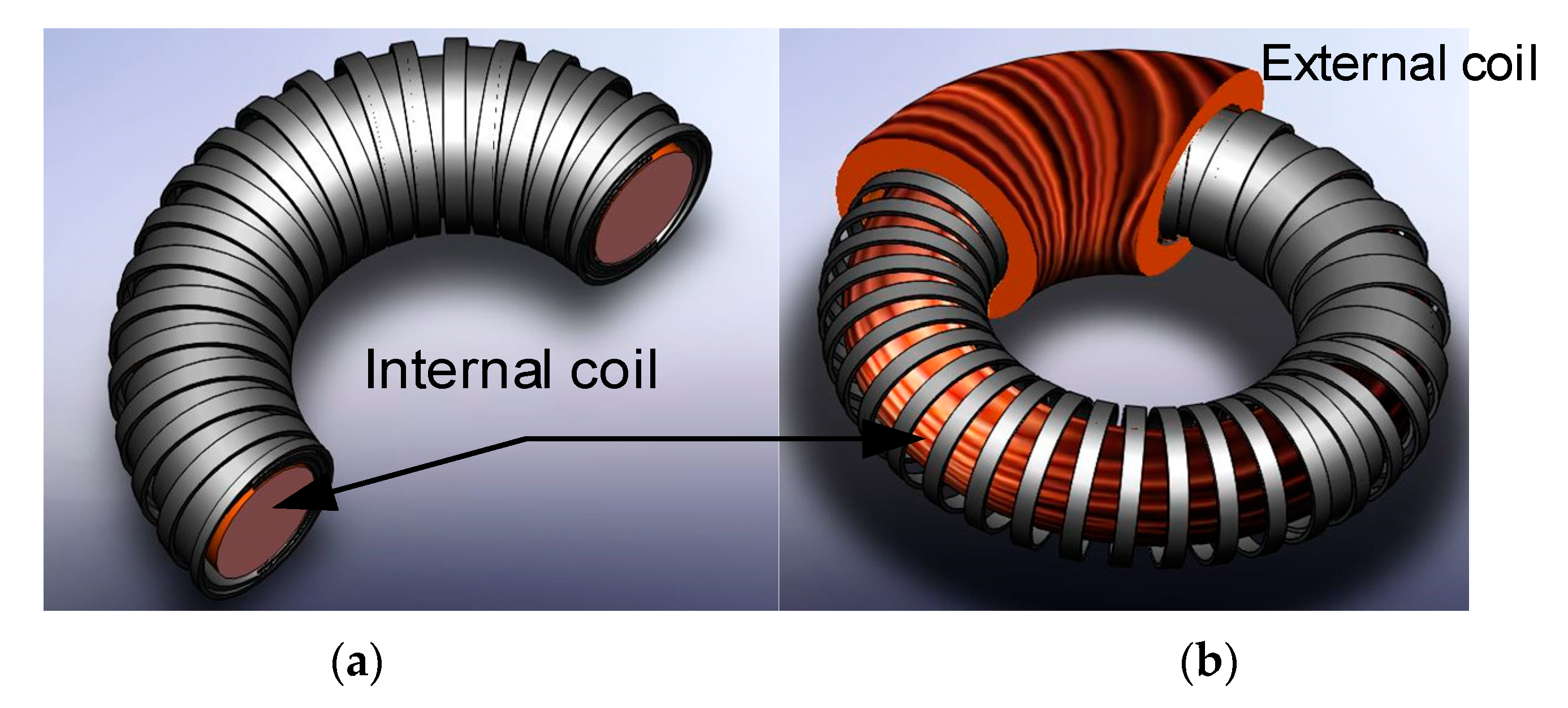
3.1. Proposed Designs

In this work, a specific method is proposed to design coils with perpendicular magnetic fields. Figure 2a,b show the schematic of the proposed design. Initially, the inner coil is wound in the toroidal direction to produce a toroidal shape. After that, a thin ribbon of ferromagnetic steel is wound on this toroidal shape in the poloidal direction to form the ferromagnetic core. The outer surface of the core should be isolated, and an external coil is wound in the poloidal direction (Figure 2b).
The winding parameters of internal coil are: N = 260 turns, diameter of wire (d) = 1 mm, RDC = 1.27 Ω, R50Hz = 28.9 Ω, L50Hz = 931 mH, whereas N = 1509 turns, d = 0.3 mm, RDC = 21.1Ω, R50Hz = 121.9Ω, L50Hz = 836.6 mH, for the external coil. The ferromagnetic core is designed using multiple ribbon sections. Two closely placed segments are attached by micro-welding. The thickness of ribbon section is 0.1 mm. The degree of independence between perpendicular windings is studied analytically and experimentally in the following sections.

3.2. The Analytical Background for the Calculation of Magnetic Coupling

This section presents the analytical background for the calculation of magnetic coupling. A preliminary analysis of magnetic coupling was discussed in our previous work [33]. Figure 3 demonstrates the equivalent circuit of the proposed MA. The equivalent first harmonic of current is employed for the analytical description. Despite having additional harmonics in the current, this method gives enough accuracy for the magnetic coupling assessment discussed in this work. Generally, the standard Kirchhoff equations can be applied for the analytical analysis.
The equivalent circuit is expressed as the following set of equations with phasor variables and parameters:
V ˙ 1 I ˙ 1 ( R 1 + j X 1 ) + j I ˙ 2 X m = 0
I ˙ 2 ( R 2 + R L + j X 2 ) + j I 1 X m = 0
where X 1 = ω L 1 , X 2 = ω L 2 ,   X m = ω L m . The dot over symbols represents the phasor variables. The inductive coupling ( K c o u p l e ) is estimated using X 1 , X 2 , and X m as follows [38]:
K c o u p l e = X m X 1 X 2
Now, the important question is how to measure all inductances ( X 1 , X 2 , and X m ). In our previous work [33], we suggested that the open-circuit test can be applied to assess magnetic coupling. For this purpose, Equations (2) and (3) are rearranged for the open-circuit case (I2 = 0) as:
{ V ˙ 1 I ˙ 1 ( R 1 + j X 1 ) = 0 V ˙ 2 + j I ˙ 1 X m = 0
And after simplification:
X m = V ˙ 2 j V ˙ 1 ( R 1 + j X 1 )
Since the magnitude of X m is the real number the angle φT = 0 it provides the following expression for the estimation of X m through the open-circuit test:
X m = V 2 V 1 R 1 2 + X 1 2 = V 2 V 1 Z 1

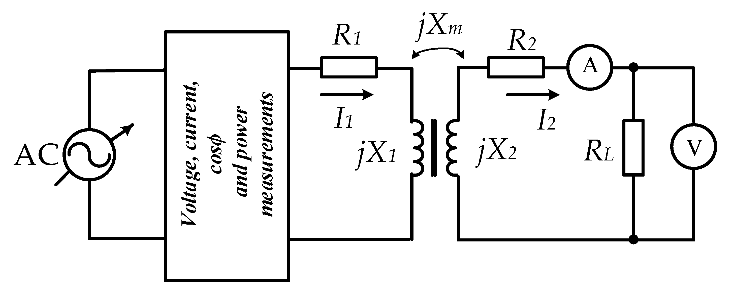
3.3. Experimental Setup

The experimental setup for the measurement of magnetic coupling is shown in Figure 4a. The experimental setup includes a voltmeter, ampere meter, wattmeter, TRMS leakage clamp with power functions (MD 9272, Metrel Co.) [39], and a digital multimeter (APPA 98IV, APPA Technology Corp.) [40]. The resistivity and inductivity of coils were measured using a handheld LCR Meter (U1732C, Keysight Technology) [41]. An autotransformer connected with a step-down transformer was also used for better control of the relatively small voltages. The coupling coefficients were measured according to an analytically developed procedure (Section 3.2). The parameters ( X m , X 1 , and X 2 ) were measured using open-circuit and short-circuit experiments. The X ˜ 2 X 2 + X m is measured during open-circuit measurements when the voltage with appropriate magnitude and 50 Hz frequency is applied on the second coil. The current’s magnitudes ( I 1 and I 2 ) were calculated through a short-circuit test. The resistances (R1 and R2) were measured with the DC current. The measurements of resistances and inductivities were carried out with the 891 Bench LCR meter [42]. For controllability measurement, the coil setup is immersed in liquid nitrogen (77 K) to minimize resistance (Figure 4b).

3.4. Controllability

The controllability analysis of the proposed design is important for the determination of the range of possible applications. It can be estimated using the change of working winding impedance by the DC current in the control coil. The equivalent circuit of working winding with the experimental setup is represented in Figure 5.

4. Results and Discussion

4.1. Magnetic Coupling

Figure 6a illustrates the relationship between impedance and resistance with the current for internal and external coils. It is important to point out that the external coil remains open circuit during the internal coil measurement and vice versa. It is observed that the impedance of both coils decreases as the current increases. The peculiarity of the magnetic curve can explain the initial decrease of impedance. The magnetic saturation is also responsible for the reduction of impedance and reactance with the current amplification. Another possible factor is the appearance of high current harmonics.
The relation between impedance and current can be approximated by the exponentiation function:
Z = a I b
where coefficients a =   23563 and b =   −0.801 for the inner coil, whereas a =   5945.2 and b =   −0.542 for the outer coil. The approximation coefficient ( R 2 ) is more than 0.99 for both coils.
Figure 6b presents the coupling coefficient ( K c o u p l e ) versus current in the internal coil. The magnetic coupling increases (~11%) as the current in the internal coil is enhanced. However, the coupling coefficient varies only ±5.5% from the average value (~0.0158) and remains constant with a relatively low magnitude. It is applicable to the controllable impedance design. The coupling coefficient can be expressed by a cubic polynomic function:
K c o u p l e = 3 10 8 I 3 3 10 6 I 2 + 8 10 5 I + 0.0148
The coefficient R 2   is equal to 0.98.

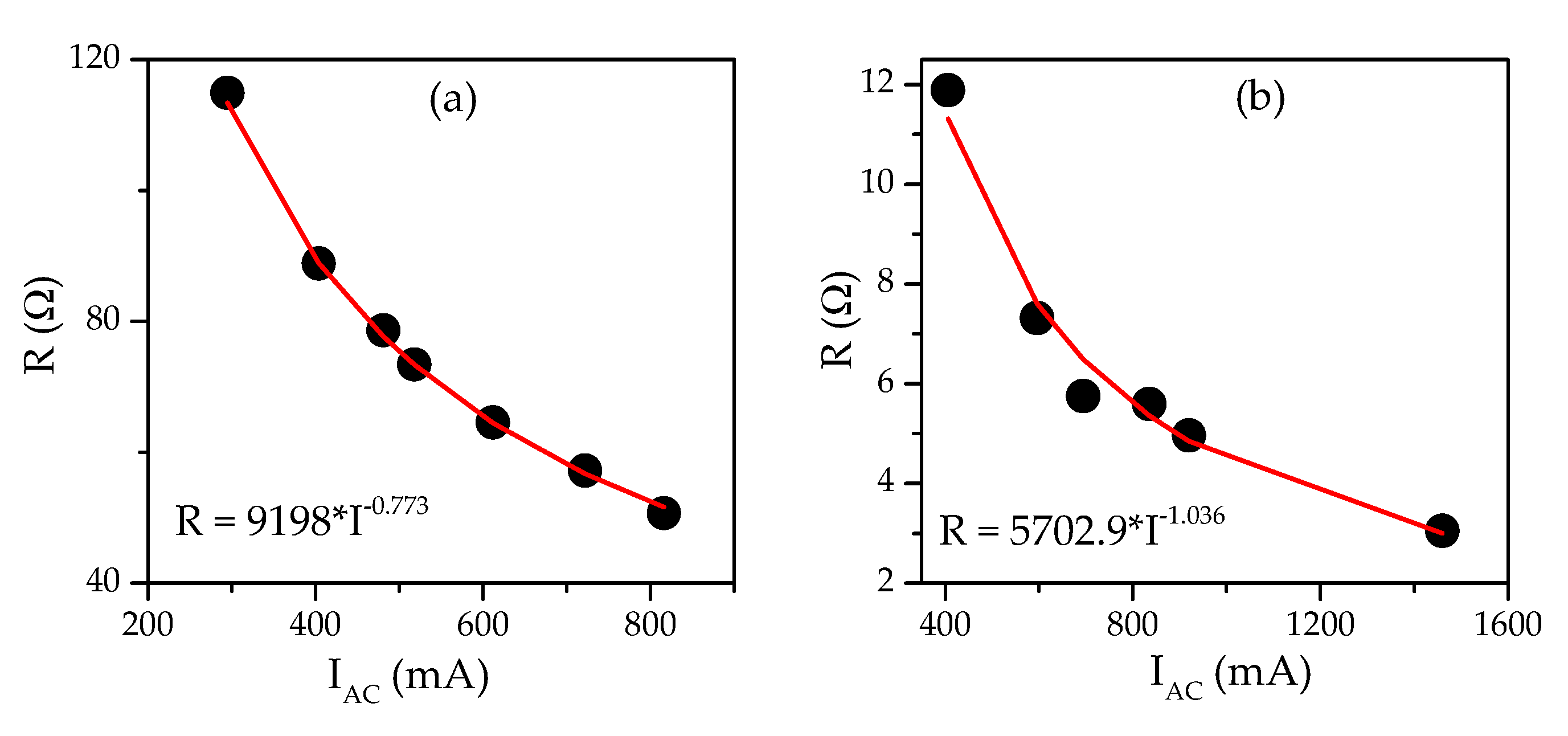
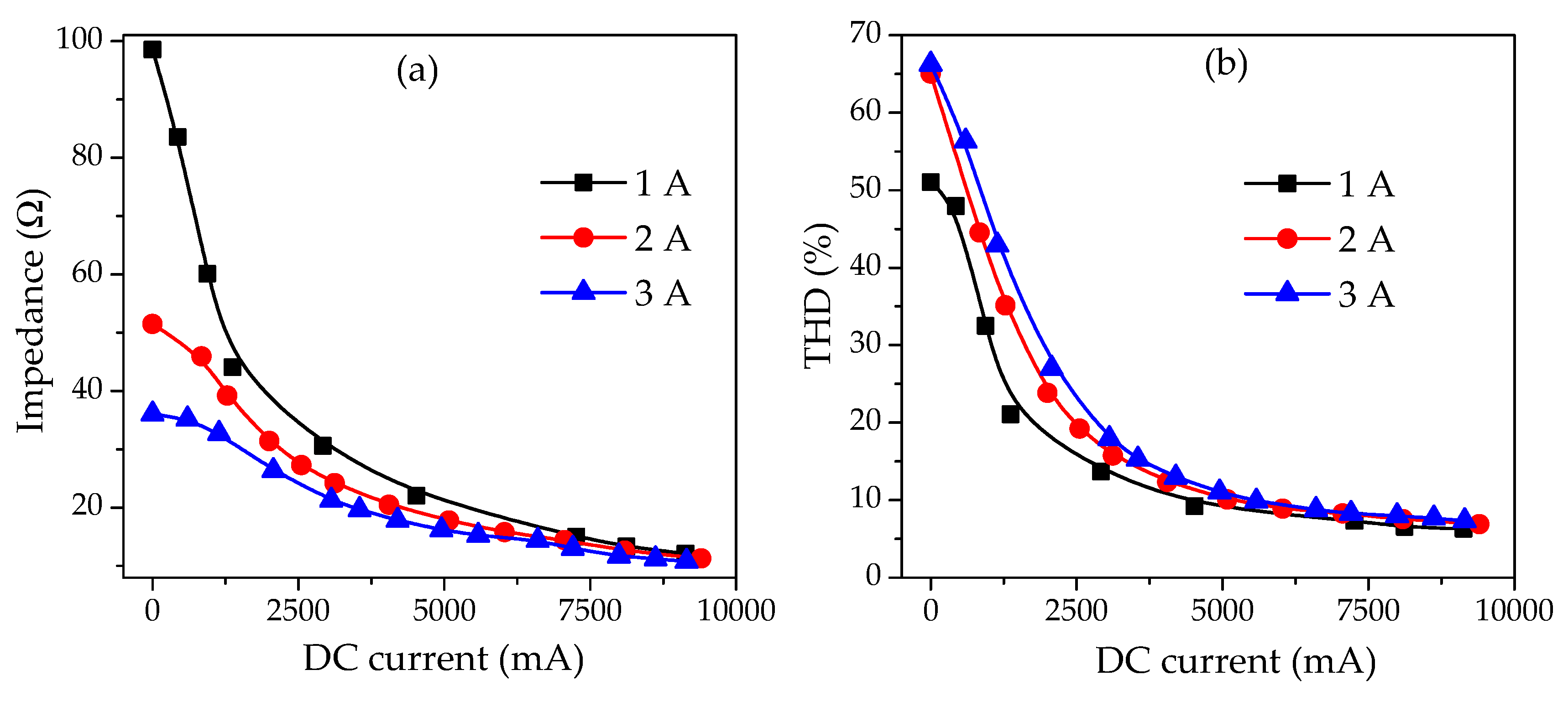
4.2. Resistance and Reactance of Coils

The resistances of both coils in the equivalent circuit are determined by the net DC conductivity, skin-effect influence, and ferromagnetic losses (eddy current and hysteresis). The resistances of both coils are shown in Figure 7a,b. The DC resistance values of both coils are 1.3 Ω and 21.3 Ω for internal and external coils, respectively. The DC resistance constitutes a small portion of the equivalent values. The diminished hysteresis losses explain the resistance drops with an increase of the current. The equivalent resistances of both coils may be described by the exponential function like (8). The expressions are shown in Figure 7a,b.
The experimental studies show that the reactance of both coils is very similar to the impedance since total losses in these coils are relatively small. The external coil reactance is almost equal to the impedance and is 99% of the impedance. The reactance of the internal coil is 91–95% of the impedance.

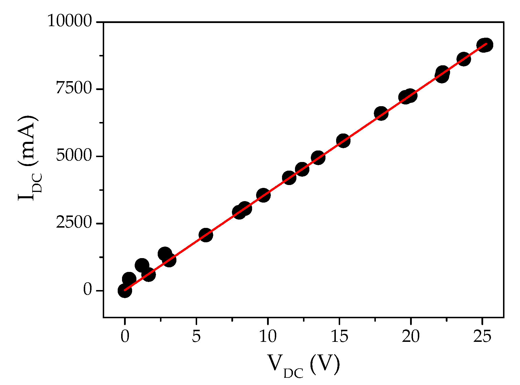
4.3. Controllability

Figure 8 represents the I–V curve of control winding immersed in liquid nitrogen. For the measurement, the control DC current is changed from 0 to ~9400 mA. The calculated resistance of working and control coils are ~0.174 Ω and 2.74 Ω, respectively (Figure 8). Copper losses can contribute a significant portion of total ones and interfere with the estimation of ferromagnetic losses. The coil is immersed in liquid nitrogen to minimize resistance influencing the copper losses. It provides the opportunity to increase the magnetic field of the control winding significantly, and the resistance of the working coil remains minimum.
The impedance and THD% were measured for different AC current of 1A, 2A, and 3A as a function of DC current. The impedance of working winding is shown in Figure 9a. It can be observed that the impedance of the working coil is changed ~ 6 times for the AC current of 1A and ~3 times for the current of 3A. These results confirm the possibility of changing the energy flow to some extent in the distribution grid and a prosumer. The characteristics of the AC current should be verified considering the presence of non-linear magnetization curves of the core. Figure 10 represents AC current shapes for DC control current of 8120 mA and 0 mA. It is observed that the current curve is distorted from a simple sinusoid curve because of the nonlinearity of the magnetization curve. The designer of a power circuit should know these circumstances and consider them in the project development.
The distorted behavior of the current is assigned to the higher THD coefficient. The THD coefficients for different DC currents are represented in Figure 9b. It is observed that the THD coefficient is higher for the lower control DC current.

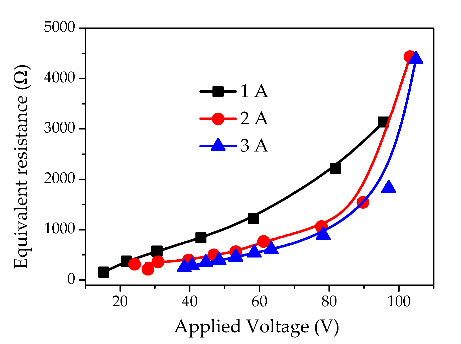
4.4. Parameters of the Equivalent Circuit

Equivalent circuit (Figure 5) parameters represent important information for the development of magnetic switching devices. The R 1 is the active resistance of the coil and can be estimated through DC measurements of the coil resistance. The inductivity ( L μ ) can be measured using special devices [43]. The resistance of magnetic losses ( R μ ) for 50 Hz can be obtained from Figure 8. It should be noted that the magnetic losses strongly depend on frequency variations. In the proposed design, the leakage flux for coils placed in ferromagnetic tubes is less than 1%. Therefore, it can be neglected for most applications. If it is necessary to consider the leakage flux, then it can be estimated as ~1% of the main inductance. Figure 11 shows the magnetic core losses at 50 Hz as a function of voltage.

5. Discussion

This work proves that the controllable magnetic impedance can be achieved by creating coils with perpendicular magnetic fields in the specially designed tubular frame. The orthogonality of coils ensures their magnetic independence. The magnetic cores designed from separated thin ribbons strips seem more promising for the design of orthogonal magnetically independent coils. This framework provides one coil with a controllable and wide range of impedance, while another magnetically independent coil can control the first one.
The magnification of impedance depends on the current and may achieve magnitude 10–15 times. It is enough for the applications. Here, we also want to point out that a small coupling (~0.015–0.017) always remains and depends on the core design. This small coupling allows the DC current in the control winding without special current sources and straightforward from an electronic controller. The magnetic non-isotropy of the ribbon exhibits higher permeability in the longitude axis than that of the latitude axis. This circumstance allows the controllability of AC coil impedance and, therefore, the flow of current through it by shifting the magnetic field of a working winding from the direction with the highest permeability to the lowest one. The proposed solution is important for the distribution lines and smart grids enriched by numerous individual power generation facilities (e.g., solar, wind, etc.). In case of any fault or emergencies, the consumer can be disconnected from the grid using substantial impedance. During this period, the consumer is supported by energy generation plants and remains in the weak galvanic connection to the grid. The consumer again connects to the grid as soon as the fault or voltage instabilities are rectified. The connection and disconnection processes take place smoothly without any problems caused by the non-synchronization of phase and frequency.

6. Conclusions

In this article, we studied the special design of orthogonal magnetic coils to produce controllable impedance. The DC current one (control) coil regulates the impedance of another one (working) coil. The degree of magnetic independence between perpendicular coils is in the range of 0.015–0.017 only. The controllability is also verified with experimental investigations. The impedance of the working coil can alter 10–15 times the initial value through the control current. It is applicable for regulating the power flow between the grid and a consumer. The equivalent resistance of the working coil is responsible for the heating represented mainly by ferromagnetic losses. Henceforth, the investigation of ferromagnetic steels should be organized to develop new materials with more anisotropy of magnetizing curves and lower losses. The electrical influence between the grid and the consumer can be significantly diminished during fault situations, and the connection remains uninterrupted. The prosumers return to usual feeding without problems caused by non-synchronization between the phases/frequencies of generators and the grid.

Author Contributions

Conceptualization, S.R., A.S. and M.A.; methodology, S.R., E.L. and M.A.; formal analysis, S.R. and E.L.; investigation, resources, and data curation, S.R., E.L., A.S. and M.A.; writing—original draft preparation, S.R., E.L. and M.A.; writing—review and editing, S.R. and M.A.; supervision and project administration, M.A. All authors have read and agreed to the published version of the manuscript.

Funding

This research received no external funding.

Conflicts of Interest

The authors declare no conflict of interest.

References

  1. Balzamov, D.S.; Akhmetova, I.G.; Balzamova, E.Y.; Oykina, G.I.; Bronsrkaya, V.V. Options for organizing own sources of energy supply at the facilities of generating companies based on steam screw machines. J. Phys. Conf. Ser. 2019, 1399, 055018. [Google Scholar] [CrossRef]
  2. Kubarkov, Y.P.; Makarov, Y.V.; Golubeva, K.A. Application of distributed generation for optimization of voltage levels in power electric systems with active-adaptive network based on genetic algorithm. In Proceedings of the Dynamics of Systems, Mechanisms and Machines (Dynamics), Omsk, Russia, 14–16 November 2017; pp. 1–4. [Google Scholar]
  3. Gerislioglu, B.; Ozturk, F.; Sanli, A.E.; Gunlu, G. The multi-windings forward structure battery balancing. In Proceedings of the 11th International Conference on Electronics, Computer and Computation (ICECCO), Abuja, Nigeria, 29 September–1 October 2014; pp. 1–4. [Google Scholar]
  4. Baev, I.; Dzyuba, A.; Solovyeva, I.; Kuzmina, N. Improving the efficiency of using smalldistributed generation systems through mechanisms of demand management for electricity and gas. Int. J. Energy Prod. Manag. 2018, 3, 277. [Google Scholar]
  5. Zafar, R.; Mahmood, A.; Razzaq, S.; Ali, W.; Naeem, U.; Shehzad, K. Prosumer based energy management and sharing in smart grid. Renew. Sust. Energy Rev. 2018, 82, 1675. [Google Scholar] [CrossRef]
  6. Liu, N.; Yu, X.; Wang, C.; Wang, J. Energy sharing management for microgrids with PV prosumers: A stackelberg game approach. IEEE Trans. Industr. Inform. 2017, 13, 1088. [Google Scholar] [CrossRef]
  7. Espe, E.; Potdar, V.; Chang, E. Prosumer Communities and Relationships in Smart Grids: A Literature Review, Evolution and Future Directions. Energies 2018, 11, 2528. [Google Scholar] [CrossRef] [Green Version]
  8. Rajput, S.; Averbukh, M.; Yahalom, A.; Minav, T. An Approval of MPPT Based on PV Cell’s Simplified Equivalent Circuit During Fast-Shading Conditions. Electronics 2019, 8, 1060. [Google Scholar] [CrossRef] [Green Version]
  9. Drabek, T.; Dybowski, P. Control of prosumer energy sources in power grid feeded by three-phase distribution transformer. In Proceedings of the 15th Selected Issues of Electrical Engineering and Electronics (WZEE), Zakopane, Poland, 8–10 December 2019; pp. 1–6. [Google Scholar]
  10. McGranaghan, M.; Houseman, D.; Schmitt, L.; Cleveland, F.; Lambert, E. Enabling the integrated grid: Leveraging data to integrate distributed resources and customers. IEEE Power Energy Mag. 2015, 14, 83. [Google Scholar] [CrossRef]
  11. Dileep, G. A survey on smart grid technologies and applications. Renew. Energy 2020, 146, 2589. [Google Scholar] [CrossRef]
  12. Rajput, S.; Amiel, I.; Sitbon, M.; Aharon, I.; Averbukh, M. Control the Voltage Instabilities of Distribution Lines using Capacitive Reactive Power. Energies 2020, 13, 875. [Google Scholar] [CrossRef] [Green Version]
  13. Bouzid, A.M.; Guerrero, J.M.; Cheriti, A.; Bouhamida, M.; Sicard, P.; Benghanem, M. A survey on control of electric power distributed generation systems for microgrid applications. Renew. Sust. Energy Rev. 2015, 44, 751. [Google Scholar] [CrossRef] [Green Version]
  14. Guihong, F.; Fengxiang, W.; Jin, W. Design principles of magnetically controlled reactor. In Proceedings of the Fifth International Conference on Electrical Machines and Systems (IEEE Cat. No. 01EX501), Shenyang, China, 18–20 August 2001; pp. 212–214. [Google Scholar]
  15. Li, D.; Tian, J. A novel variable reactor with transformer and inverter control. In Proceedings of the International Conference on Electrical Machines and Systems, Wuhan, China, 17–20 October 2008; pp. 4440–4443. [Google Scholar]
  16. Mingxing, T.; Qingfu, L. Magnetic saturation type and transformer type controllable shunt reactor. High Volt. Eng. 2003, 7, 001. [Google Scholar]
  17. Yang, X.; Yue, C. Orthogonal flux controllable reactor for transmission lines. In Proceedings of the International Conference on Power System Technology, Hangzhou, China, 24–28 October 2010; pp. 1–4. [Google Scholar]
  18. Ben-Yaakov, S.; Peretz, M.M. A self-adjusting sinusoidal power source suitable for driving capacitive loads. IEEE Trans. Power Electr. 2006, 21, 890. [Google Scholar] [CrossRef]
  19. Shafaghatian, N.; Heidary, A.; Radmanesh, H.; Rouzbehi, K. Microgrids interconnection to upstream AC grid using a dual-function fault current limiter and power flow controller: Principle and test results. IET Energy Syst. Integr. 2019, 1, 269. [Google Scholar] [CrossRef]
  20. Wilson, T.G. The evolution of power electronics. IEEE Trans. Power Electr. 2000, 15, 439. [Google Scholar] [CrossRef]
  21. Dimitrovski, A.; Li, Z.; Ozpineci, B. Magnetic amplifier-based power-flow controller. IEEE Trans. Power Deliv. 2015, 30, 1708. [Google Scholar] [CrossRef]
  22. Young, M.A., II; Dimitrovski, A.D.; Patterson, R.W.; Liu, Y. Impacts of a Magnetic Amplifier-Based Power Flow Controller on Power System Distance Protection; Oak Ridge National Lab (ORNL): Oak Ridge, TN, USA, 2014. [Google Scholar]
  23. Lin, K.; Tomsovic, K.; Wan, Q.; Dimitrovski, A. A Study of Magnetic Amplifier-based Power Flow Controller for Power System Stability Improvement. Electr. Power Compon. Syst. 2016, 44, 966. [Google Scholar] [CrossRef]
  24. Ibrahim, R.A.; Hamad, M.S.; Ahmed, K.H.; Dessouky, Y.G.; Williams, B.W. Improved ride-through of PMSG wind turbine during symmetrical voltage dip using a magnetic amplifier. In Proceedings of the 2nd IET Renewable Power Generation Conference (RPG 2013), Beijing, China, 9–11 September 2013; pp. 1–6. [Google Scholar]
  25. Yaskiv, V.; Yaskiv, A.; Abramovitz, A.; Smedley, K. Performance evaluation of MagAmp regulated isolated AC-DC converter with high PF. In Proceedings of the 2014 IEEE ELEKTRO, Rajecke Teplice, Slovakia, 19–20 May 2014; pp. 411–416. [Google Scholar]
  26. O’Grady, C.M. Magnetic Amplifiers for Voltage Regulation Applications; Undergraduate Honors College, University of Arkansas: Fayetteville, NC, USA, 2015. [Google Scholar]
  27. Liu, W.; Luo, L.; Dong, S.; Lou, Y. Overview of power controllable reactor technology. Energy Procedia 2012, 17, 483–491. [Google Scholar] [CrossRef] [Green Version]
  28. Ko, J.-H.; Baek, S.-W.; Lee, K.-M.; Kim, H.-W.; Cho, K.-Y.; Kim, J.-M. Hybrid Current-Mode Control of PSFB Converter to Compensate Slew Interval and Prevent Magnetic Saturation of Transformers. Electronics 2020, 9, 1395. [Google Scholar] [CrossRef]
  29. Sedykh, O.A. Calculation of magnetic amplifiers with toroidal cores. Avtom. Telemekhanika 1956, 17, 445. [Google Scholar]
  30. Qiu, M.; Rao, S.; Zhu, J.; Fu, S.; Li, Z.; Liu, W.; Chen, P.; Gong, J. Energy storage characteristics of MJ-class toroidal HTS-SMES considering maximum value of perpendicular magnetic field. Energy Procedia 2017, 105, 4179–4184. [Google Scholar] [CrossRef]
  31. Aganza-Torres, A.; Pfeiffer, J.; Zacharias, P. Interleaved Buck Converter with Coupled Inductors as Auxiliary Bias-Current Source for Controllable Magnetic Devices. In Proceedings of the PCIM Europe Digital Days 2020; International Exhibition and Conference for Power Electronics, Intelligent Motion, Renewable Energy and Energy Management, Berlin, Germany, 7–8 July 2020; pp. 1–8. [Google Scholar]
  32. Zacharias, P.; Kleeb, T.; Fenske, F.; Wende, J.; Pfeiffer, J. Controlled magnetic devices in power electronic applications. In Proceedings of the 19th European Conference on Power Electronics and Applications (EPE’17 ECCE Europe), Warsaw, Poland, 11–14 September 2017; pp. 1–10. [Google Scholar]
  33. Lokshin, E.; Minav, T.; Averbukh, M. Minimization Magnetic Coupling of Perpendicular Coils Winded Inside and Outside Toroidal Core made Thin Magnetic Ribbon. In Proceedings of the IEEE International Conference on the Science of Electrical Engineering in Israel (ICSEE), Eilat, Israel, 12–14 December 2018; pp. 1–4. [Google Scholar]
  34. Shirkoohi, G.; Arikat, M. Anisotropic properties of high permeability grain-oriented 3.25% si-fe electrical steel. IEEE Trans. Magn. 1994, 30, 928–930. [Google Scholar]
  35. Păltânea, V.; Paltanea, G. Study of the Magnetic Anisotropy of the Grain Oriented (GO) and Non-Oriented (NO) Silicon Iron Materials. Mater. Sci. Forum 2011, 670, 66–73. [Google Scholar]
  36. Chwastek, K.R.; Baghel, A.P.S.; De Campos, M.F.; Kulkarni, S.V.; Szczygłowski, J. A description for the anisotropy of magnetic properties of grain-oriented steels. IEEE Trans. Magn. 2015, 51, 1. [Google Scholar]
  37. Paltanea, V.M.; Paltanea, G.; Gavrila, H.; Dumitru, L. Experimental analysis of magnetic anisotropy in silicon iron steels using the single strip tester. In Proceedings of the 9th International Symposium on Advanced Topics in Electrical Engineering (ATEE), Bucharest, Romania, 7–9 May 2015; pp. 456–459. [Google Scholar]
  38. Irwin, J.D.; Nelms, R.M. Basic Engineering Circuit Analysis; John Wiley & Sons: Hoboken, NJ, USA, 2007. [Google Scholar]
  39. TRMS Leakage Clamp (Metrel MD9272) with Power Functions. Available online: https://www.test-meter.co.uk/metrel-md-9272-trms-leakage-clamp-with-power-functions/ (accessed on 30 December 2019).
  40. APPA 90IV SERIES MULTIMETERS. Available online: http://www.appatech.com/en/product-553890/APPA-90IV-SERIES-MULTIMETERS-APPA-98IV.html (accessed on 4 June 2018).
  41. KEYSIGHT U1733C LCR Meter. Available online: https://www.keysight.com/en/pd-1984428-pn-U1732C/100hz-120hz-1khz-10khz-handheld-lcr-meter?cc=IL&lc=eng (accessed on 21 January 2020).
  42. 300kHz Bench LCR Meter. Available online: https://www.bkprecision.com/products/component-testers/891-300khz-bench-lcr-meter.html (accessed on 14 July 2020).
  43. Suresh, V.; Abudhahir, A. An analytical model for prediction of magnetic flux leakage from surface defects in ferromagnetic tubes. Meas. Sci. Rev. 2016, 16, 8–13. [Google Scholar]
Figure 1. (a) The schematic of load power regulation through controllable reactance, (b) Non-linear magnetic curves of controllable reactance for different DC currents in the control winding [B is magnetic flux density, φ is magnetic flux, l is the average path of magnetic lines in the core, A is cross-section of core, H is field strength, I is current in the coil, WP1 is working point at I1, and WP2 is working point at I2].
Applsci 10 07645 g001
Figure 2. Schematic representation of principle to create two perpendicular coils (a) internal winding covered with ferromagnetic ribbon, (b) external coil on the ferromagnetic core.
Applsci 10 07645 g002
Figure 3. Equivalent circuit of two coupled magnetic coils [AC: controllable voltage source; ω: frequency of voltage source; R1, R2: equivalent resistances of coupled windings; Lσ1, Lσ2: inductivities of magnetic leakage paths in both coils; Lσm: mutual inductance between windings; A/V: tester for voltage and current measurements].
Applsci 10 07645 g003
Figure 4. (a) Experimental setup for coupling measurement, (b) coil immersed in liquid nitrogen.
Applsci 10 07645 g004
Figure 5. The equivalent circuit of the experimental setup for coil controllability measurement: R1—pure ohmic resistance of a working coil; Lleak—inductance of a leakage magnetic field; Rμ—resistance representing energy losses in the core; Lμ—inductance of the coil; Ic—coil current; Iloss—current representing core losses; Iμ—magnetization current.
Applsci 10 07645 g005
Figure 6. (a) Impedance of the internal and external coils. The external coil remains open circuit during the measurement of the internal coil and vice versa. (b) Coupling coefficient as a function of current in internal coil. Solid lines represent the approximation.
Applsci 10 07645 g006
Figure 7. Equivalent resistance of (a) external coil and (b) internal coil. Solid lines represent the approximation. The approximation coefficient ( R 2 ) is more than 0.99.
Applsci 10 07645 g007
Figure 8. I–V curve of control winding. The resistance is calculated using the I–V curve.
Applsci 10 07645 g008
Figure 9. (a) Working coil impedance versus DC control current. (b) total harmonic distortion (THD) of a working current depending on DC control current.
Applsci 10 07645 g009
Figure 10. Voltage-current shapes for different DC control currents (a) 8120 mA, (b) 0 mA.
Applsci 10 07645 g010
Figure 11. Equivalent parallel resistance (for 50 Hz), which is designated as magnetic core losses.
Applsci 10 07645 g011
Publisher’s Note: MDPI stays neutral with regard to jurisdictional claims in published maps and institutional affiliations.

