Article

Line of Sight and Image Motion Compensation for Step and Stare Imaging System

Key Laboratory of Airborne Optical Imaging and Measurement, Changchun Institute of Optics, Fine Mechanics and Physics, Chinese Academy of Science, Changchun 130033, China
*
Author to whom correspondence should be addressed.
Appl. Sci. 2020, 10(20), 7119; https://doi.org/10.3390/app10207119
Submission received: 7 August 2020 / Revised: 26 September 2020 / Accepted: 3 October 2020 / Published: 13 October 2020
(This article belongs to the Section Earth Sciences)

Abstract

:

Featured Application

The step and stare system introduced in this article can be used in the system with high needs for geo-location and resolution applications, such as marine search and rescue, border patrol, etc.

Abstract

In recent years, applications such as marine search and rescue, border patrol, etc. require electro-optical equipment to have both high resolution and precise geographic positioning abilities. The step and stare working based on a composite control system is a preferred solution. This paper proposed a step and stare system composed of two single-axis fast steering mirrors and a two-axis gimbal. The fast steering mirrors (FSMs) realize image motion compensation and the gimbal completes pointing control. The working principle and the working mode of the system are described first. According to the imaging optical path, the algorithm and control flow of the line of sight (LOS) and image motion compensation are developed. The proposed method is verified through ground imaging and flight tests. Under the condition of flight, the pointing accuracy of the target can be controlled within 15 m. The proposed algorithm can achieve effective motion compensation and get high-resolution images. This achieves high resolution and accurate LOS simultaneously.

1. Introduction

In recent years, electro-optic/infrared imaging systems with high resolution, wide area, and accurate geo-positioning characteristics are required for search and rescue, border and coastal patrol, and other applications. For the above requirements, the system should have a long focal length, high imaging frame frequency, and high geo-locating accuracy. Such systems have three imaging patterns: linear array scanning, step and stare, and scan stare imaging patterns [1]. Step and stare imaging pattern in which the line of sight (LOS) is stepped to a position and held for some time and then stepped to a new position. This type of scan is often used when a pattern of several small images are to be stitched together in a mosaic to form a larger image and should be preferred when more accurate geo-location is required [2].
There are two primary architectures for the step and stare imaging system: two-axis gimbaled systems and two-axis gimbaled systems with steering mirrors. Two-axis gimbaled systems are switched to perform LOS pointing and motion compensation. They are the simplest and lowest cost. However, they are not suitable for high frame frequency applications because of the larger payload. Two-axis gimbaled systems with steering mirrors provide more stability but with greater cost and complexity [3]. This architecture can choose two single-axis steering mirrors and one two-axis steering mirror. Considering the nonlinear coupling and complexity of control, one two-axis steering mirror is generally only used in limited space. If the space allowed, two single-axis steering mirrors can be preferred. The description is detailed in Table 1. The system described in this paper has a suitable space, so it chooses the architecture of a two-axis gimbal with two single-axis steering mirrors.
The step and stare imaging system needs to focus on how to achieve an accurate line of sight or image motion compensation. The way of using two-axis or multi-axis gimbals to achieve stabilization of the LOS is described in many early documents [4,5,6,7,8,9].With the emergence and development of fast steering mirrors, the literature began to use the fast steering mirrors(FSMs) with two-axis gimbals to realize the composite systems to achieve more accurate and fast stabilization of LOS. Most of these systems focus on the tracking system and pay more attention to the stabilization accuracy of the LOS of the system rather than the imaging resolution [10,11,12,13]. The above literature does not combine the LOS and image motion compensation. The system described in this article needs to achieve high-resolution images while achieving LOS stability. That means, to reach the LOS pointing position before the imaging exposure, and to carry out image motion compensation during the exposure. Thus, we will focus this paper on LOS and image motion compensation for step and stare imaging system which uses two-axis gimbal with two single-axis steering mirrors.
The layout of the rest of this paper is as follows. The second part of this article describes the composition, working principle, and imaging optical path. In the third part, the LOS and motion compensation kinematics and algorithm are described. The method proposed in this paper is verified by ground and flight tests in the fourth part, and the conclusions got from the tests are expounded. The test results are discussed and summarized in Section 5.

2. Step and Stare Imaging System

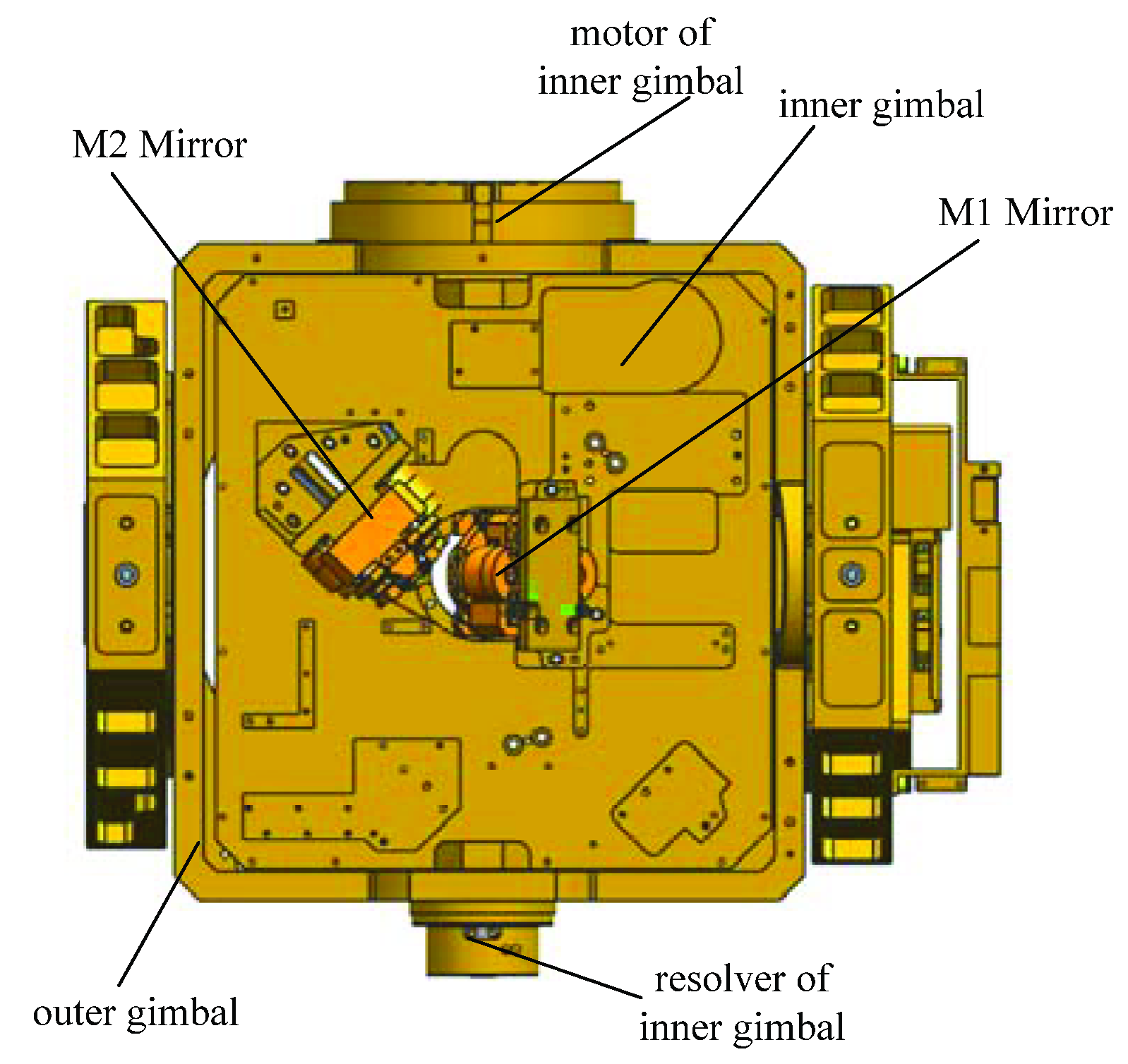
2.1. System Components and Operating Principle

Rapid step and star imaging system is mainly composed of an optical subsystem, command and algorithm unit, gimbaled subsystem, mirror subsystem and detector. The gimbaled subsystem consists of two axes of roll and pitch, which is used to achieve the bore sight pointing before exposure. The mirror subsystem is composed of rotating mirrors and fixed mirrors. The rotating mirrors are used to achieve image motion compensation during the exposure, and they are M1 and M2 mirrors which are fast steering mirrors. The fixed mirrors are used to realize optical path rotation, which is convenient to realize position layout. The gimbal and the rotating mirrors are shown in Figure 1.
The working principle of the system and timing diagram is shown in Figure 2. Based on the position information of the ground target, the command and algorithm unit calculates the respective two-axis gimbaled command angle. The gimbaled controller drives the gimbal to step to the corresponding angle before exposure and keeps the inertial space position stable during the exposure. The mirror system is used to compensate for the image movement caused by the speed, attitude movement of the plane, and the gimbal; the detector collects imagery. After one exposure, the command and algorithm unit gives the next gimbaled command angle according to the geospatial position and overlap ratio. The gimbal system and the mirror system repeat the tasks in the previous frame process. Repeatedly, the images at each location are then stitched together to form a large but high-resolution mosaic image [14].

2.2. Imaging Optics Path

The schematic diagram of the imaging optical path of the system is shown in Figure 3. The beam of the ground target is incident into the detector through M1, M2, M3, and M4 mirrors. The outer gimbal rotates around the pitch axis, and the inner gimbal rotates around the roll axis. Whether the outer or the inner gimbal rotates, it drives the mirror system and detector to rotate synchronously. In the mirror system, the M1 mirror and M2 mirror are rotating mirrors, which respectively compensate for the image motion in roll and pitch directions. M3 and M4 mirrors are fixed mirrors, which mainly realize the internal optical path turning so that the light can be injected into the detector.

3. LOS and Motion Compensation Kinematics and Algorithm

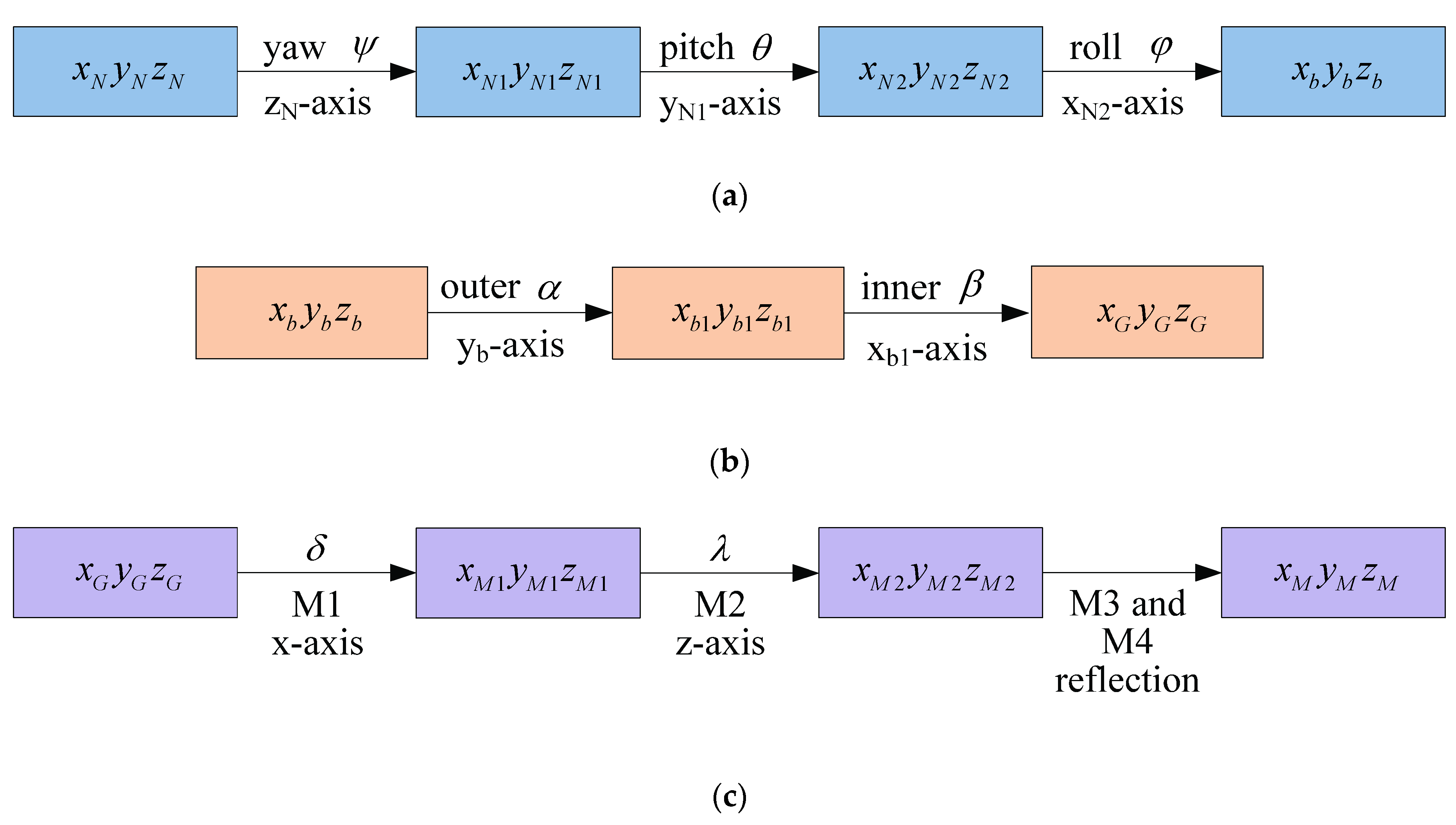
3.1. Coordinate Frames

Four principal coordinate frames are used in the system. These are the geographical coordinate frame, the aircraft body coordinate frame, the gimbal coordinate frame and the mirror coordinate frame, and all of the coordinate frames follow the “right-hand” coordinate system.
Geographical coordinate frame: this frame is the reference coordinates, in which GPS/IMU carries out navigation computations. Its center of this frame is at the intersection of the IMU axes, and this coordinate can use either north-east-down (NED) or east-north-up (ENU) Cartesian coordinate forms. As interesting objects are below the aircraft, it is a more intuitive selection of the NED coordinate system. This coordinate frame is denoted by the symbol N.
Aircraft body coordinate frame: this coordinate frame also has its origin at the GPS/IMU location. Its axes are consistent with that of GPS/IMU. When the GPS/IMU is in parallel with the aircraft, its x-axis points to the flight direction, and they-axis is orthogonal with the x-axis and refers to the right, then the z-axis completes the orthogonal right-handed set. This coordinate frame is denoted by the symbol b.
Gimbal coordinate frame: gimbal axes are aligned to the aircraft body axes at zero gimbal angles. The outer gimbal axis is coincident with the aircraft pitch axis at zero roll gimbal angle. The inner gimbal axis is coincident with the aircraft roll axis at zero pitch gimbal angle. This coordinate frame is denoted by the symbol G.
Mirror coordinate frame: all the mirrors are mounted on the inner gimbal. M1 mirror is a roll mirror and rotates about the x-axis. When its angle is zero, its normal vector is tilted 45° with the x-axis of the gimbal. M2 mirror is a pitch mirror and rotates about the z-axis. When its angle is zero, its normal vector is tilted through 45° with the y-axis of the gimbal. M3 and M4 mirrors are fixed mirrors. Their normal vector is respectively tilted through −45° and −135° with the z-axis of the gimbal. This coordinate frame is denoted by the symbol M [15,16].

3.2. Analysis of Coordinate Transformation

The transformation among coordinate frames are shown in Figure 4.
From the geographical coordinate frame to the aircraft body coordinate frame, the angle of yaw is represented with Ψ, pitch is represented with θ, and roll is represented with φ. The transform of C N b is:
C N b = ( 1 0 0 0 cos φ sin φ 0 sin φ cos φ ) ( cos θ 0 sin θ 0 1 0 sin θ 0 cos θ ) ( cos ψ sin ψ 0 sin ψ cos ψ 0 0 0 1 )
From the aircraft body coordinate frame to the gimbal coordinate frame, the angle of the outer gimbal is represented with α, and the angle of the inner gimbal is represented with β. Then C b G is:
C b G = ( 1 0 0 0 cos β sin β 0 sin β cos β ) ( cos α 0 sin α 0 1 0 sin α 0 cos α )
According to Snell’s Law, the transformation of the incident vector Pi to the reflected vector Po by the mirror can be represented by the Equation (3) [17,18,19]:
P o = T × P i
The matrix T is a transform in terms of the mirror normal components, Nx, Ny, and Nz written as:
T = ( 1 2 N x 2 2 N x N y 2 N x N z 2 N x N y 1 2 N y 2 2 N y N z 2 N x N z 2 N y N z 1 2 N z 2 )
Thus, C G M is:
C G M = ( 0 1 0 1 0 0 0 0 1 ) T 4   f r o m   N 4 ( 0 1 0 1 0 0 0 0 1 ) T 3   f r o m   N 3 ( sin 2 λ cos 2 λ 0 cos 2 λ sin 2 λ 0 0 0 1 ) T 2   f r o m   N 2 ( 1 0 0 0 sin 2 δ cos 2 δ 0 cos 2 δ sin 2 δ ) T 1   f r o m   N 1
The matrices in the Equation (5) are calculated from the normal vectors according to Equation (4), which are as follows:
N 1 = ( 0 cos ( δ + 45 ° ) sin ( δ + 45 ° ) ) T
N 2 = ( cos ( λ + 45 ° ) sin ( λ + 45 ° ) 0 ) T
N 3 = ( 2 2 2 2 0 ) T
N 4 = ( 2 2 2 2 0 ) T

3.3. LOS Command Angle

According to the working principle, LOS is realized by the gimbaled subsystem. To keep LOS stable, it is necessary to adjust the pointing of the inner and outer gimbals in real-time with the change of the attitude of the aircraft. Therefore, the LOS command angle refers to the pointing angle of the gimbal.
In the geographical coordinate frame, the coordinates of the target and the aircraft are respectively ( x T N , y T N , z T N ) and ( x b N , y b N , z b N ) . L is defined as the photographic distance, and its expression is:
| ( x TN x bN ) 2 + ( y TN y bN ) 2 + ( z TN z bN ) 2 |
Then the unit vector of the LOS pointing is:
( u Nx u Ny u Nz ) = 1 L ( x TN x bN y TN y bN z TN z bN )
Converting the vector to that in the aircraft body coordinate is:
( u bx u by u bz ) = C N b ( u Nx u Ny u Nz )
Then the pointing angles of the inner gimbalsαand the outer gimbalsβare:
α = arctan ( u by u bz )
β = arcsin ( u bx )
The functional block diagram and control sequence are shown in Figure 5.

3.4. Image Motion Compensation

Three factors cause the image motion in the system: the linear speed of the aircraft, the angular rate of the aircraft, and the angular rate of the gimbals. As mentioned above, the image motion compensation is implemented by the mirror rotating around the corresponding axis. Therefore, it is necessary to convert various types of image motions into angular rates of the corresponding axes in the mirror coordinate.
According to the principle that the linear speed is vertical to the LOS of a point that lies on the LOS vector, the equations are developed for the linear speed of the aircraft. Dividing the orthogonal components by the range to the point, then yields the two angular LOS rates orthogonal to the LOS that are required for control [18].M3 and M4 are fixed mirrors, which are used to reflect the LOS into the detector and are not used for compensation. So the coordinate transformation here can only be converted to the M2 mirror, that is T3 and T4 were ignored in Equation (5). Converting the linear speed of the aircraft, (VNx, VNy, VNz)T in the geographic coordinate frame to that in the mirror coordinate system is:
( V M x V M y V M z ) = C G M 2 × C b G × C N b ( V N x V N y V N z )
The resulting angular rates in the mirror system are:
ω VMy = V Mx 2 L
ω VMx = V My 2 L
The transformation of the angular rates of the aircraft and the gimbal to the mirror coordinate can be expressed as follows:
( 1 0 0 0 sin 2 δ cos 2 δ 0 cos 2 δ sin 2 δ ) { ( 1 0 0 0 cos β sin β 0 sin β cos β ) [ ( cos α 0 sin α 0 1 0 sin α 0 cos α ) ( ω bx ω by ω bz ) + ( 0 α ˙ 0 ) ] + ( β ˙ 0 0 ) } + ( 2 δ ˙ 0 0 )
where α ˙ and β ˙ are the angle rates of the gimbal, and δ ˙ is the angle rate of the M1 mirror. ω bx , ω by , and ω bz are the angle rates of roll, pitch and yaw respectively in the aircraft body coordinate frame.
After calculation, the compensation velocities of M1 and M2 mirrors are as follows:
ω M 1 x = β ˙ + ω bx cos α + ω bz sin α + 2 δ ˙
ω M 2 z = 2 λ ˙ + cos 2 δ [ cos β ( α ˙ + ω by ) + sin β ( ω bz cos α + ω x sin α ) ] sin 2 δ [ sin β ( α ˙ + ω by ) cos β ( ω bz cos α + ω x sin α ) ]
where λ ˙ is the angle rate of the mirror of M2.
To ensure the image speed on the focal plane is zero, it is only necessary to ensure that Equations (19) and (20) are equal to zero. Then the compensation speeds of M1 and M2 mirrors are:
δ ˙ = β ˙ + ω bx cos α + ω z sin α 2
λ ˙ = cos 2 δ [ cos β ( α ˙ + ω by ) + sin β ( ω bz cos α + ω x sin α ) ] sin 2 δ [ sin β ( α ˙ + ω by ) cos β ( ω bz cos α + ω x sin α ) ] 2
From the above equations, it can be known the angular rate that the M1 mirror required to rotate is consistent with the value sensed by the gyro of the inner gimbal. So it can be obtained directly by collecting the value of the inner gimbal gyro. However, the angular rate of the M2 mirror is related to several parameters, including the current angle of the M1 mirror, the angles and angular rates of the inner and outer gimbals, and the angular rates of the aircraft. If a gyro can be installed on the z-axis of the M1 mirror, the rate sensed by this gyro can be used as the compensation parameter of the M2 mirror. However, because of limiting installation space, the axis cannot be installed with a gyro. Considering the parameters required by the M2 mirror are only used as the inputs of the system, and its control feedback uses a special position sensor, so the requirements for the acquisition bandwidth of the above parameters are not high. And therefore, the sensors installed on the gimbals, M1 mirror and the aircraft can be used, then the compensated parameters can be obtained by calculation. The block diagram of the system is shown in Figure 6.

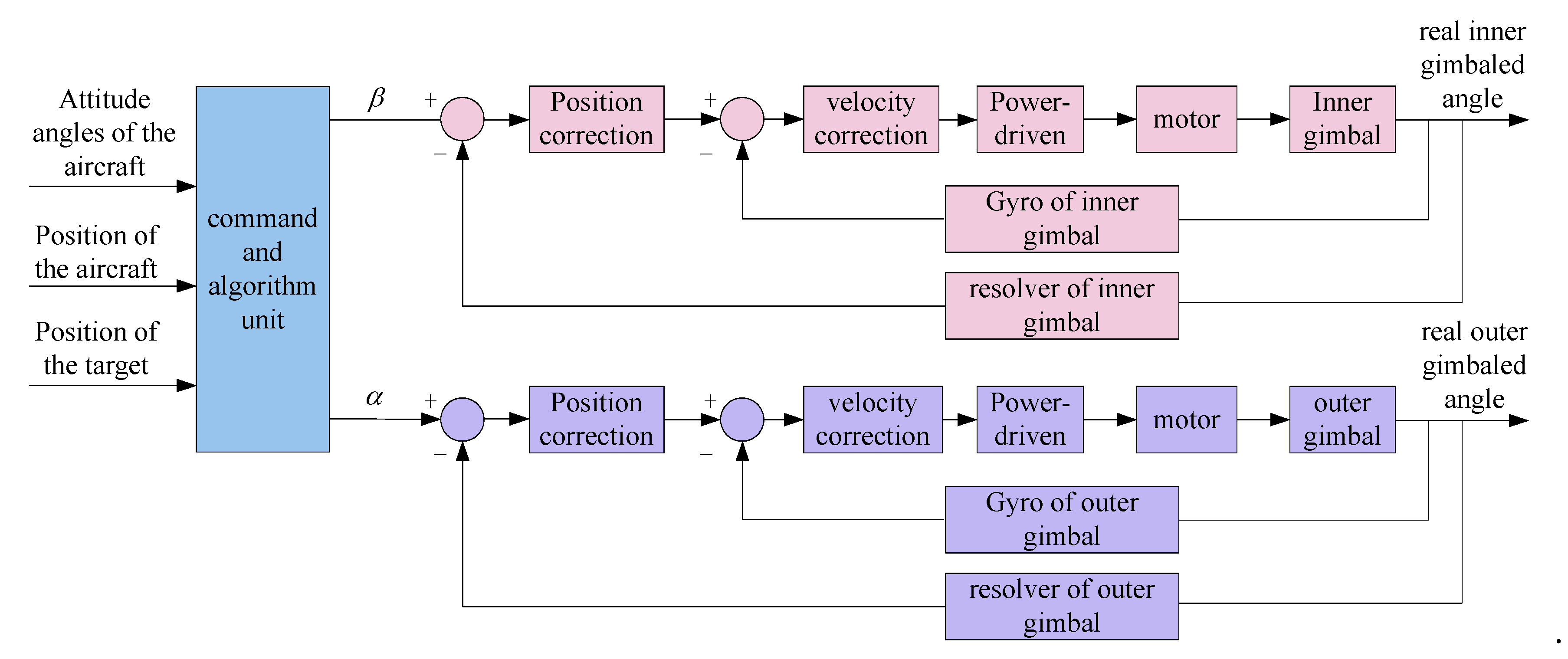
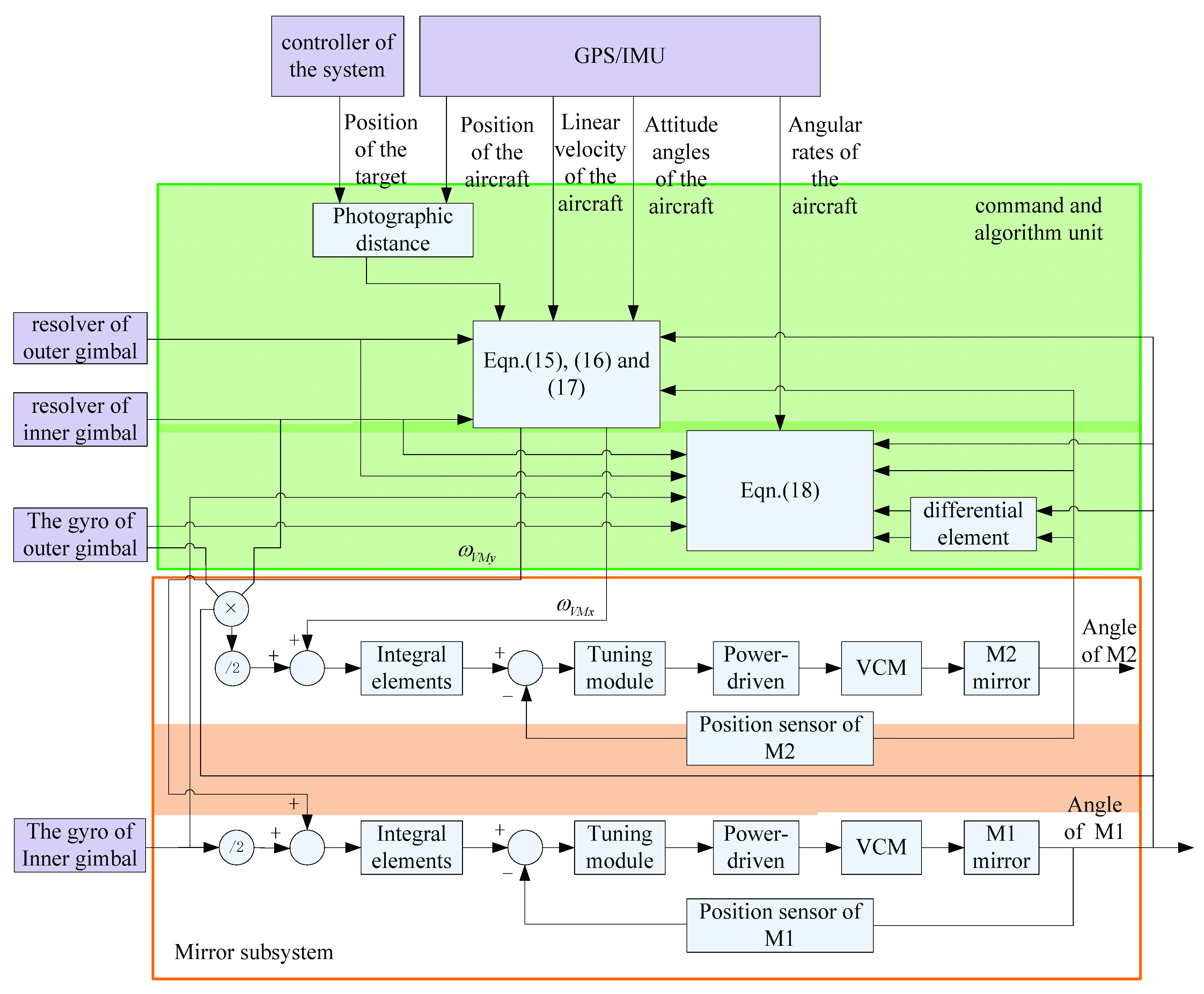
3.5. Control Process

The imaging time of each frame is 60ms.After receiving the target position information, the command and algorithm unit starts to calculate the working parameters required by the gimbal and FSMs. According to the method described in Section 3.3, the gimbaled command angles are calculated in real-time based on information such as the position of the target point and the aircraft, the attitude of the aircraft. Similarly, as described in Section 3.4, the velocities of image motion compensation are calculated. After the frame cycle starts, the gimbaled command angle required by the current target position is updated in real time and sent to the gimbal subsystem, and the “step” command is started at the same time. Then the gimbal is controlled to move to the position indicated by the command angle. To reserve start time for FSMs, the command and algorithm unit send image motion compensation (IMC) command before exposure. During the exposure, the gimbal subsystem keeps the LOS stable, and FSMs compensate according to the real-time velocities. After the exposure is completed, the command and algorithm unit starts to send the gimbaled command angles of the next frame, which is repeated to achieve high-precision positioning and high-resolution imaging. The control flow chart is shown in Figure 7.

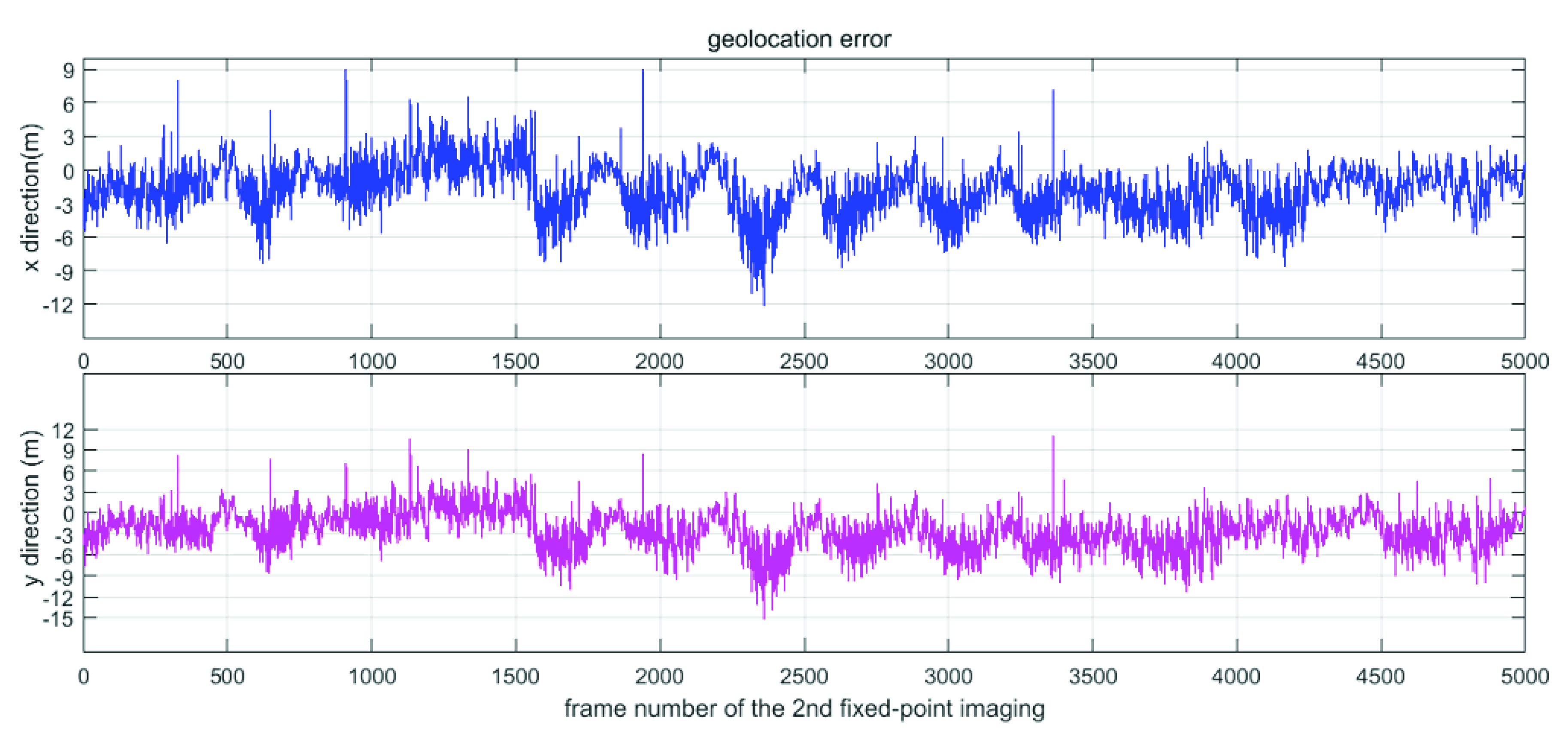
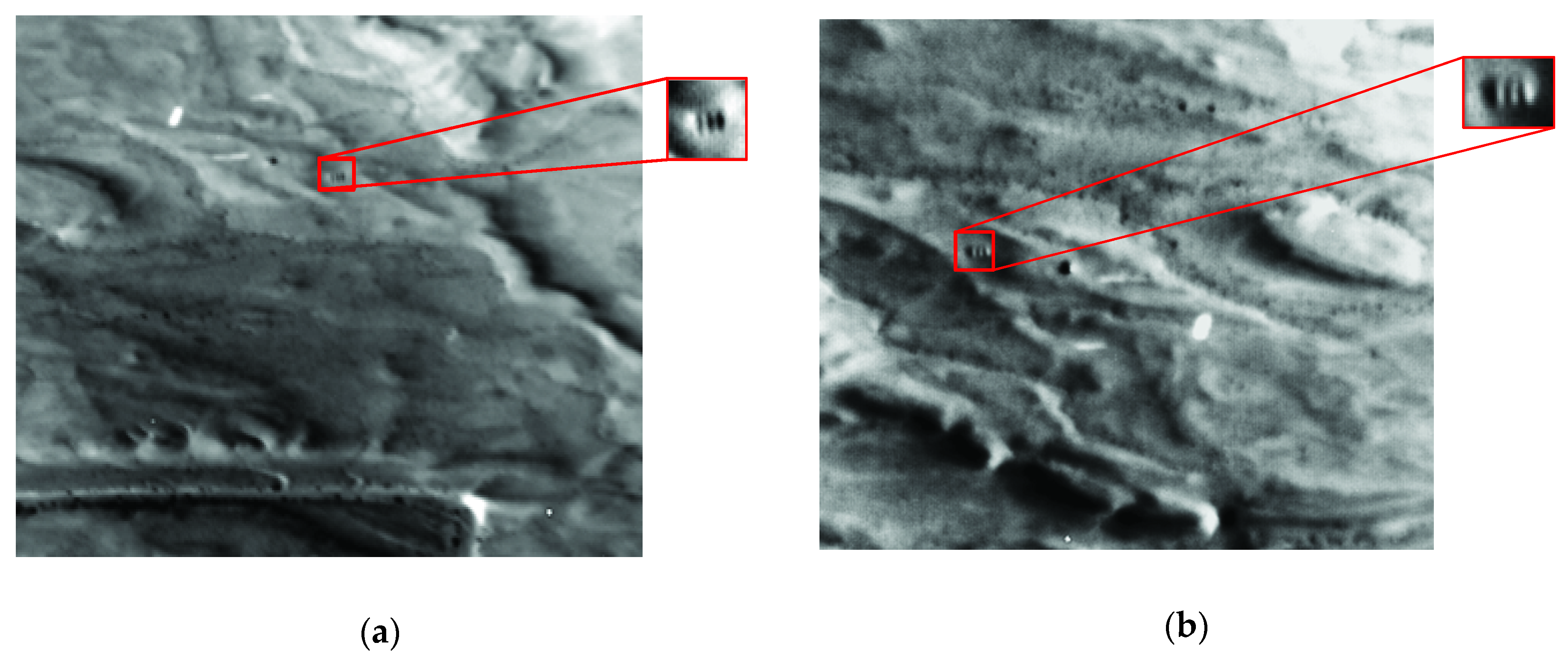
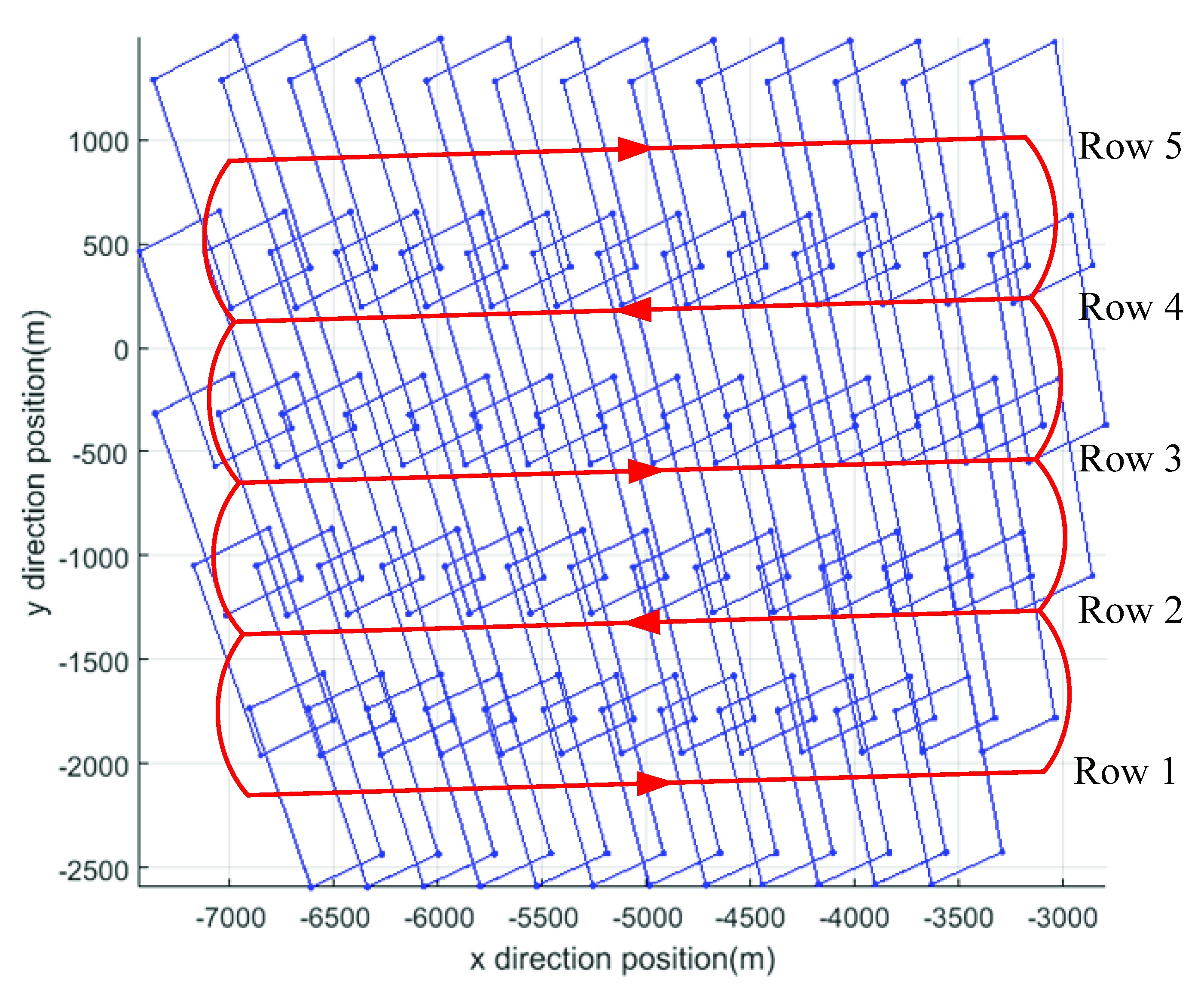
4. Experiments and Results

To verify the method of LOS and image motion compensation, a series of flight tests were performed. The flight altitude t of the aircraft is about 7400m, and the photographing distance is from 22 km to 24 km. There are two kinds of imaging methods: fixed-point mode and search mode. Fixed-point mode imaging refers to the continuous imaging of fixed target points on the ground. And search mode refers to seamless coverage imaging of an area on the ground.
In the fixed-point mode, the coordinate of the target is fixed and is located in (0,0,0). With the aircraft flying, the gimbaled command angles and velocities of IMC are calculated in real time. The gimbal subsystem adjusts the pointing angles to keep the LOS point to the fixed target. At the same time, according to the flight information of the aircraft, the actual gimbaled angles and the position of the compensation mirrors, the LOS and the corresponding ground target coordinates can be calculated reversely. And the position deviation between the planned imaging target and the actual target point can be obtained. Figure 8 shows the data that the system performs fixed-point imaging in two different directions. Although the position of the aircraft changes greatly, LOS always points to the fixed target and images the target from all angles. Due to the measurement errors of various sensors, the errors of the control system and other reasons, there will be position deviations in the imaging projection area on the ground. The position deviation of roll and pitch directions are within 15 m, as shown in Figure 9. In the exposure process, FSMs adjust the position in real time according to the given speeds to keep the image clear. Figure 10 is photographed images of the two fixed-point imaging in the mid wave infrared (MWIR) band. The tri-bar can be clearly distinguished from the detailed enlarged pictures.
In the search mode, the target coordinates are variable. In the case of ensuring the overlap, different targets are imaged in sequence, to perform search imaging on an area. The command and algorithm unit calculates the gimbaled command angles of the current target and sends it to the gimbal subsystem before exposure. The position of the target is always maintained during the exposure, and it switches to the command angles of the next target after the exposure is completed. To improve efficiency, the system step and start back and forth. The first row is from left to right, the second one is the opposite. The roll gimbaled angle changes greatly with each frame step, while pitch gimbaled angle changes greatly with each row step. Figure 11 is the ground imaging projection map in search mode. It can be seen that it can achieve the coverage imaging of the area and meet the overlapping requirements. The real-time changes of the gimbaled angles are shown in Figure 12. During each frame, the gimbaled angles approach gradually the command angles and keep stable until the next command angles are received. Figure 13 shows the positions of the FSMs at the exposure time in the search process. Since the step direction is opposite after each row, the compensation direction of the next row is reversed.

5. Conclusions

In this paper, a novel step–stare system was proposed, which was composed of two single-axis fast steering mirrors and a two-axis gimbal. The two-axis and four-frame system proposed in the past is mainly used to solve the problem of LOS pointing. A two-axis gimbal is used to achieve large-angle pointing and “coarse” control, and FSMs are used to achieve “finer” LOS pointing. The system proposed in this paper is time-sharing. The gimbal is mainly used to control the LOS before exposure and keep the LOS during exposure, while FSMs are used to compensate the image motion during exposure, so as to achieve accurate LOS and high-resolution imaging at the same time. This paper introduced the working principle and system composition of the system established the coordinate system and proposed the algorithm of LOS and image motion compensation (IMC) based on the imaging optical path. Finally, the correctness of the algorithm and control flow was verified by flight test. The composite step and stare system can be used in the system with high requirements for geo-location and resolution.

Author Contributions

Conceptualization, J.X.; software, J.X., P.H. and J.L.; validation, J.X., P.H., J.L., H.Z. and Y.L.; writing—original draft preparation, J.X.; writing—review and editing, J.X. and P.H. All authors have read and agreed to the published version of the manuscript.

Funding

This research was funded by the National high resolution project of China, grant number [GFZX0403260312].

Conflicts of Interest

The authors declare no conflict of interest.

References

  1. Hilkert, J.M. Inertially stabilized platform technology Concepts and principles. IEEE Control Syst. Mag. 2008, 28, 26–46. [Google Scholar]
  2. Hilkert, J.M. Kinematic algorithms for line-of-sight pointing and scanning using INS/GPS position and velocity information. Proc. SPIE 2005, 5810, 11–22. [Google Scholar]
  3. Miller, J.L.; Way, S.P.; Ellison, B.; Archer, C.L. Design challenges regarding high- definition electro-optic/infrared stabilized imaging systems. Opt. Eng. 2013, 52, 1841–1843. [Google Scholar] [CrossRef]
  4. Miller, R.; Mooty, G.; Hilkert, J.M. Gimbal system configurations and line-of-sight control techniques for small UAV applications. Proc. SPIE 2013, 8713, 871308. [Google Scholar]
  5. Hilkert, J.M. A unique three-axis gimbal mechanism. Proc. SPIE 2008, 6971, 69710E.1–69710E.8. [Google Scholar]
  6. Osborne, J.; Hicks, G.; Fuentes, R. Global analysis of the double-gimbal mechanism. IEEE Control Syst. Mag. 2008, 28, 44–64. [Google Scholar]
  7. Hilkert, J. A comparison of inertial line-of-sight stabilization techniques using mirrors. Proc. SPIE 2004, 5430, 13–22. [Google Scholar]
  8. Battistel, A.; Lizarralde, F.; Hsu, L. Inertially stabilized platforms using only two gyroscopic measures and sensitivity analysis to unmodeled motion. In Proceedings of the American Control Conference, Montreal, QC, Canada, 27–29 June 2012; pp. 4582–4587. [Google Scholar]
  9. Mokbel, H.F.; Ying, L.Q.; Roshdy, A.A.; Hua, C.G. Modeling and Optimization of Electro-Optical Dual Axis Inertially Stabilized Platform. In Proceedings of the 2012 International Conference on Optoelectronics and Microelectronics, Changchun, China, 23–25 August 2012; pp. 372–377. [Google Scholar]
  10. Haessig, D.A., Jr.; Towaco, N.J. Mirror Positioning Assembly for Stabilizing the Line-of-Sight in a Two-Axis Line-of-Sight Pointing System. U.S. Patent 5220456, 15 June 1993. [Google Scholar]
  11. Wang, Y. Research on High Precision LOS stabilization Technology Based on Fast Steering Mirror. Ph.D. Thesis, Changchun Institute of Optics, Fine Mechanics and Physics, Chinese Academy of Science, Beijing, China, 2016. (In Chinese). [Google Scholar]
  12. Wang, L.; Liu, X.; Wang, C. Line-of-sight kinematics modeling and correction for precision pointing systems based on a two-axis fast steering mirror. Opt. Eng. 2019, 58, 084110. [Google Scholar] [CrossRef]
  13. Zhou, Q.; Ben-Tzvi, P.; Fan, D.; Goldenberg, A.A. Design of Fast Steering Mirror systems for precision laser beams steering. In Proceedings of the 2008 International Workshop on Robotic and Sensors Environments, Ottawa, ON, Canada, 17–18 October 2008; pp. 144–149. [Google Scholar]
  14. Hilkert, J.M.; Kanga, G.; Kinnear, K. Line-of-sight kinematics and corrections for fast-steering mirrors used in precision pointing and tracking systems. Proc. SPIE 2014, 9076, 90760F. [Google Scholar]
  15. National Geospatial-Intelligence Agency. Frame Sensor Model Metadata Profile Supporting Precise Geopositioning; SIG. 0002–2.1; National Geospatial-Intelligence Agency: Fort Belvoir, VA, USA, 2011. [Google Scholar]
  16. Held, K.J.; Brendan, H.R. Tier II Plus Airborne EO sensor LOS control and Image geolocation. In Proceedings of the IEEE 1997 IEEE Aerospace Conference, Aspen, CO, USA, 13 February 1997; pp. 377–405. [Google Scholar]
  17. Debruin, J.C. Derivation of line-of-sight stabilization equations for gimbaled-mirror optical systems. Proc. SPIE 1991, 1543, 236–247. [Google Scholar]
  18. Hilkert, J.M.; Cohen, S. Development of mirror stabilization line-of-sight rate equations for an unconventional sensor-to-gimbal orientation. Proc. SPIE 2009, 7338, 733803. [Google Scholar]
  19. Royalty, J.M. Line-of-Sight Kinematics for a Two-Axis Head Mirror: Equations for predicting and controlling mirrored LOS pointing. Proc. SPIE 2009, 7338, 733804. [Google Scholar]
Figure 1. Diagram of compensating mirror and gimbal.
Applsci 10 07119 g001
Figure 2. Working principle and timing diagram; (a) working principle; (b) timing diagram.
Applsci 10 07119 g002
Figure 3. Imaging optical path of the system.
Applsci 10 07119 g003
Figure 4. Transformation relationship (a) from the geographical coordinate frame to the aircraft body coordinate frame, denoted by C N b ; (b) from the aircraft body coordinate frame to the gimbal coordinate frame, denoted by C b G ; (c) from the gimbal coordinate frame to the mirror coordinate frame, denoted by C G M .
Applsci 10 07119 g004
Figure 5. Block diagram of gimbaled control.
Applsci 10 07119 g005
Figure 6. Block diagram of image motion compensation.
Applsci 10 07119 g006
Figure 7. Control flow chart of the system.
Applsci 10 07119 g007
Figure 8. Aircraft flight path and ground imaging projection when the system performs fixed-point imaging in two different directions.
Applsci 10 07119 g008
Figure 9. Target positioning accuracy in X and Z directions for the second fixed-point imaging.
Applsci 10 07119 g009
Figure 10. Photographed images of the two fixed-point modes (a) image obtained from the first fixed-point imaging; (b) image obtained from the second fixed-point imaging.
Applsci 10 07119 g010
Figure 11. The ground imaging projection map in search mode.
Applsci 10 07119 g011
Figure 12. The gimbaled angles in search mode.
Applsci 10 07119 g012
Figure 13. The position of the FSMs in search mode.
Applsci 10 07119 g013
Table 1. Typical architectures for line of sight (LOS) and motion compensation.
Work ModeAdvantageDisadvantage
two-axis gimbalgimbal switches to complete LOS and motion compensationsimple structure and low costlimited stability and performance, not suitable to high-resolution and high frequency
two-axis gimbal with two single-axis steering mirrorsgimbal works for LOS pointing, and steering mirrors work for motion compensation of respective axis accurate stability and low payloadhigh cost and complexity. Compared to the two-axis mirror, they need more space.
two-axis gimbal with one two-axis steering mirrorgimbal works for LOS pointing, and steering mirror work for motion compensation of two-axisaccurate stability and low payloadCompared to two single-axis mirrors, it has nonlinear coupling, and the control algorithm is more complicated

