Featured Application
Testing system of multisensory human–machine interfaces for blind and visually impaired people’s navigation. Indoor and outdoor, as well as virtual and real environments are supported.
Abstract
In this paper, the Virtually Enhanced Senses (VES) System is described. It is an ARCore-based, mixed-reality system meant to assist blind and visually impaired people’s navigation. VES operates in indoor and outdoor environments without any previous in-situ installation. It provides users with specific, runtime-configurable stimuli according to their pose, i.e., position and orientation, and the information of the environment recorded in a virtual replica. It implements three output data modalities: Wall-tracking assistance, acoustic compass, and a novel sensory substitution algorithm, Geometry-based Virtual Acoustic Space (GbVAS). The multimodal output of this algorithm takes advantage of natural human perception encoding of spatial data. Preliminary experiments of GbVAS have been conducted with sixteen subjects in three different scenarios, demonstrating basic orientation and mobility skills after six minutes training.
1. Introduction
Recent scientific and technological advances have opened new possibilities in the development of navigation systems, i.e., systems that provide required or helpful data to get to a destination point, specifically adapted for blind and visually impaired (BVI) users. Current market-available devices range from applying Bluetooth Low Energy (BLE) beacons for user positioning [1], to the usage of computer vision to analyze key features of the user’s surroundings [2].
However, several issues remain, especially in terms of data acquisition, e.g., the detection and identification of obstacles in the user’s path; human-machine interfaces, e.g., how to provide the user with the ever-rich, visual-type data of their surroundings; production costs; etc. Particularly, non-intrusive human-machine interfaces act as a bottleneck of the information that can be conveyed to the user. As described in a previous review, this has limited the potential of several proposals [3]. These interfaces must provide adequate data output to the remnant sensory capabilities. In the event of severe or total sensory loss, it is necessary to make use of alternative sensory modalities.
In this context, the present work focuses on developing more effective and efficient non-visual, human–machine interfaces for navigation systems for BVI people. To that end, previous and novel solutions are integrated in a highly configurable, mixed-reality system. In addition to an acoustic compass and a wall-tracking assistance feature, it includes Geometry-Based Virtual Acoustic Space: A novel, multimodal sensory substitution algorithm which takes advantage of the perceptual and higher cognitive processes of touch and hearing. Conversely to previous projects, the visual and acoustic output, as well as the virtual scenario, can be configured from a server at runtime. Scenarios of various sizes and complexity can be used, from simple mazes to urban environments with moving vehicles.
2. Related Work
To date, several approaches for BVI people’s navigation have been tested [3]. According to the objectives pursued, the requirements of the human–machine interface vary. The first distinction can be made between those that focus on assisting the user in orientation and/or mobility tasks. Although there is no standard definition of these terms, in the literature ‘orientation’ or ‘wayfinding’ relates to the ability to know and continuously update one’s own position, and moving in the environment in relation to a destination [4]. Conversely, ‘mobility’ relates to “immediate responses to environmental features” [5], involving the “detection and avoidance of obstacles or drop-offs in the path of travel” [4].
Linguistic-based interfaces are the most extended for orientation purposes. This could be appreciated in currently available smartphone applications such as WayFindr [6], NavCog [1] or NaviLens [7]. However, these interfaces showed severe throughput restrictions [3] and were found non-optimal even for simple left/right cues [8]. Other interfaces incorporated non-linguistic solutions, ranging from spatialized audio to haptic displays. For instance, Head-Related Transfer Function (HRTF) sound processing and motion capture systems were applied to guide BVI users along a route by reproducing virtual sound sources at intermediate points [9]. Also, hand-held devices were developed which provided verbal messages according to the position pointed at, or tapped, on a map [10,11]; others change shape to provide heading cues [12].
Another main set of non-linguistic solutions adapted stimuli from one sensor modality to another, i.e., sensory substitution. Not limited to orientation, systems in this line of work strive to assist BVI people in navigation by mapping visual-to-tactile and visual-to-acoustic stimuli.
Some of the first devices encoded low-level visual information in acoustic/tactile stimuli, e.g., pixel data from video frames. As could be appreciated in Bach-y-Rita’s et al.’s TVSS [13] and Meijer’s vOICe [14] these systems do provide users with visual-like perceptions [15,16] but the amount of data that can be conveyed is severely restricted. Some of the major constraints are the “difference of throughput data capability between sensory modalities (bandwidth), and the compatibility with higher-nature cognitive processes” [3,17]. On the other hand, several sensory substitution systems extracted high-level information out of raw measurements and exploited the natural capabilities of the remaining sensory modalities to assimilate such information.
As an example of the latter, in the Virtual Acoustic Space project [18] the 3D surfaces in front of the user were captured by means of stereovision, and thereafter an array of virtual sound sources—stereopixels—were generated over these surfaces. As stated, this was perceived as a “large number of raindrops striking the surface of a pane of glass”. This specific visual-to-auditory mapping made use of the capability of hearing to locate audio sources, infer room size from the reverberation, etc. A later test showed how blind subjects were able to use these acoustic cues to build a schematic of their environment without relying on touch [19].
Additionally, the Haptic Radar project [20] consisted of a wearable set of IR proximity sensors paired with haptic actuators. Distance measurements from objects were encoded in vibration intensity, effectively providing the user with intuitive information regarding the presence/absence of and distance from objects in multiple directions at the same time. Untrained test subjects were able to detect and avoid unseen approaching objects. Similarly, the ENVS project [21] encoded distance measurements as haptic stimuli in the user’s fingers. As stated by the researchers, it seemed as if things were touched from a distance.
Although these visual-to-auditory and visual-to-tactile sensory substitution interfaces showed positive results, their development was conditioned to the currently available technology. One of the major restrictions lies in the type and amount of information that could be extracted from raw data of transductors, e.g., cameras or IR-sensors. In this regard, several projects utilized previously modelled data of the environment, thus allowing isolation of the design and optimization of the human–machine interface from the data acquisition system. For example, some projects offer virtual-reality platforms which allow users to explore scenery prior to travelling, by means of an avatar controlled by the user and a virtualized sensory substitution device [22,23].
In opposition to the pre-journey solutions of virtual reality, mixed reality promotes its usage in actual navigation scenarios. Several projects in this line of work implement sensory substitution interfaces using periodic measurements of the user’s position and body movement [24]. Simultaneous Locating and Mapping technology (SLAM) from Google Tango eased the development of interfaces for BVI people’s navigation, which required no additional infrastructure installation [25,26]. This can be also applied to systems such as Google ARCore [27], which capture the motion of compatible smartphones through Concurrent Odometry and Mapping technology (COM).
In this context, the developed prototype is a mixed-reality system which integrates previous and novel human–machine interfaces to assist BVI people in actual navigation scenarios. It relies on ARCore’s COM, thus no in-situ installation is needed to track the users’ movement. All required data of the surroundings are previously registered, which served to further improve previous sensory substitution algorithms; see Section 3.1.3.
3. Materials and Methods
3.1. The Virtually Enhanced Senses System
Next, the VES system is described throughout three sub-sections. Firstly, the user requirements are briefly discussed. Secondly, general features and system architecture are described. Finally, the third section delves into several key algorithms which convert useful data for BVI navigation into acoustic stimuli.
3.1.1. User Requirements
In this section we consider the navigation system interface design from the perspective of a total loss of visual information. The information provided can afterwards be adapted for specific user profiles, as both needs and means of assistance mainly vary according to the type and degree of visual loss.
Required data for navigation are summarized below [28]:
- “The presence, location, and preferably the nature of obstacles immediately ahead of the traveler.” This relates to obstacle avoidance support;
- Data on the “path or surface on which the traveler is walking, such as texture, gradient, upcoming steps,” etc.;
- “The position and nature of objects to the sides of the travel path,” i.e., hedges, fences, doorways, etc.;
- Information that helps users to “maintain a straight course, notably the presence of some type of aiming point in the distance,” e.g., distant traffic sounds;
- “Landmark location and identification,” including those previously seen, particularly in (3);
- Information that “allows the traveler to build up a mental map, image, or schema for the chosen route to be followed.” (see “Cognitive Mapping” in [29]).
Even if such information is contained in the device, it must also be conveyed to the user within a time window, e.g., when triggering obstacle detection warnings. This leads to the study of the bandwidth of the remaining sensory modalities, and how to make use of it without masking natural stimuli useful for navigation, e.g., listening to traffic sounds. Furthermore, it is necessary to adapt the output data to higher-nature cognitive processes [17]. Therefore, and given the larger bandwidth of vision, among other sensory modalities, task-oriented interfaces are required to minimize the amount of data provided.
However, the theoretical basis which sustains the design of these interfaces is a currently active research area. For instance, there is still no consensus regarding the capabilities of the targeted public to acquire spatial knowledge, e.g., how the absence of vision degrades mental representations of the environment in terms of performance in subsequent navigation tasks [5]; the role of landmarks in the development of such representations [29]; etc.
Nevertheless, previous works provide several useful cues for efficient tactile and acoustic spatial data encoding, such as the importance of the motor-sensing loop or the role of synesthesia, cortical plasticity and even rote learning. In addition, recent work in neuroscience provides new insights into the perceptual and cognitive processes involved [17,30]. The contributions range from studies on the visual acuity of sensory substitution devices [31,32], to the analysis of correlated neural activity, e.g., activation of the Visual Word Form Area (VWFA) and Fusiform Face Area (FFA) of the visual cortex through tactile/acoustic stimuli [30].
3.1.2. System Architecture
The VES system is a software application developed with Unity game engine (v2018.2.18f1, Unity Technologies), Vuforia (v8.0.10, PTC), Resonance Audio (v1.2.1, Google) and ARCore (v1.5.0, Google). It runs on a hardware platform composed of two modules (Figure 1): The equipment carried by the user, i.e., earphones and two smartphones; and a smartphone or laptop used as a server.
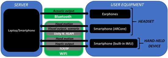
Figure 1.
System architecture.
As stated before, the system generates stimuli according to the movements of the user. In this regard, the ARCore-compatible smartphone tracks the head pose of the user in the environment, while the remaining smartphone tracks hand movements. These data are provided to a server within a few tens of meters’ radius from the position of the user, data which are updated each 20 ms. Finally, the server is used to control the multisensory feedback and the scenario to be loaded. Also, it allows for one-way communication with the user through a built-in call feature.
Once the system starts running, the headset waits for an anchor image which fixes a virtual scenario to a specific position in the real world. The movement of the user—head and hand—is then captured and synchronized with an avatar’s in a virtual scenario.
Some of the developed virtual scenarios are replicas of real environments, which were previously recorded with a 3D camera (Figure 2b). To assist navigation in real spaces, virtual and real environments are aligned by placing the anchor image in a preset position.
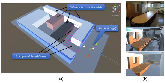
Figure 2.
(a) Elements of a virtual scenario (b) Development of a virtual replica of a real scenario. Up-to-down, the room is recorded with a 3D camera and then is rebuilt with primitives.
All virtual scenarios are constructed with primitive geometries, such as cubes, spheres or cylinders, both to lessen computing costs and avoid unnecessary data for BVI people’s navigation. These primitives are mapped to an acoustic material used to model reverberation, impact sounds, etc. Particularly, Resonance Audio has been used to simulate early and late reflections in different locations according to the arrangement of primitives (Figure 2a).
The acoustic feedback is generated according to the user’s movement, the scenario loaded and the chosen algorithms which trigger the stimuli, i.e., output modes. VES can also provide visual feedback, a feature which is currently limited to on/off options. However, it offers post-processing of the virtual camera’s output, which can be applied to simulate several visual impairments for sighted users or to enhance visually impaired users’ residual vision.
As for the output modes, the system currently supports the following:
- Geometry-based Virtual Acoustic Space (GbVAS): This includes three novel main modes of stimulation based on the Virtual Acoustic Space project, and a speech synthesis module. It provides information concerning points 1, 3, 5 and 6 of Section 3.1.1. Further details will be described in the next sub-section;
- Acoustic Compass: This provides the user with a fixed orientation cue through spatialized audio. Therefore, it directly addresses point 4;
- Wall-tracking assistance: This novel mode, which was specifically requested by the end users, is meant to help them move parallel to a wall (points 3, 4). Once the user distances from a reference wall, a haptic warning will be triggered in the hand-held device, and a virtual sound source will be spawned in the closest point of the closest wall. The position of this sound source will be periodically updated according to the user’s movement. When the user reaches a threshold distance, the virtual sound source will be turned off.
3.1.3. Geometry-Based Virtual Acoustic Space
The output mode described in this section is intended to provide information from points 1 and 3–6 of Section 3.1.1, taking advantage of several perceptual and cognitive factors.
In opposition to low-level sensory substitution, high-level information (e.g., the size, form, and composition of objects) is encoded in acoustic stimuli. Also, it exploits the natural capabilities of hearing, such as sound source localization and material discrimination.
The stimuli are generated in virtual volumes fixed to the user body, e.g., the hand or head, to allow intuitive active perception in a motor-sensory loop schema. In this regard, we start from the premise that simple object geometries could be intuitively assimilated by the user’s kinesthetic sense, as could be seen in the Haptic Radar project. Redundancy in these rudimentary extended touch and acoustic sensations is then used to reinforce distance perception beyond arm reach (points 1, 3, 5 and 6 of Section 3.1.1). Furthermore, it pursues the perception of distance in different directions, which is a feature related to vision that is of key importance in the development of a mental representation of the environment [29,33] (point 6).
This output mode is further divided into three sub-modes which can be simultaneously executed: Projected VAS, Aural VAS, and Flashlight.
The first sub-mode, Projected VAS (PVAS), is a variation of the VAS project [19]. Instead of a stereo-vision device, PVAS uses data of the virtual scenario. This allows one to model the material of each element, filter which of them trigger acoustic feedback, customize the detection range of virtual sensors, etc. Also, the spawning process of the audio sources differs from the original system.
Analogously to VAS, this output mode generates an array of virtual sound sources located over the surfaces in front of the user. Particularly, it makes use of a virtual field of view of configurable range (Figure 3) which originates between the user’s eyes. The sound sources are spawned sequentially over the surfaces within the field of view.
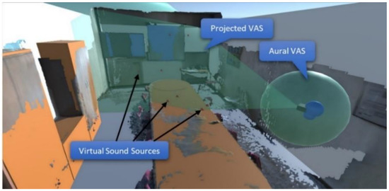
Figure 3.
Projected and Aural VAS.
The primitives which comprise all the elements of the scenario are mapped to an acoustic material. For this output mode, several impact sounds were recorded as split-second mono audio tracks, each one linked to a specific acoustic material. Once a sound source is spawned over an element’s surface, it reproduces an audio track corresponding to that primitive’s material, and is deleted afterwards.
The audio sources are positioned according to an array of MxN elements. Each one of these elements provides a spawn position within the PVAS field of view, , and an audio track corresponding to the material of the primitives, (Figure 4).
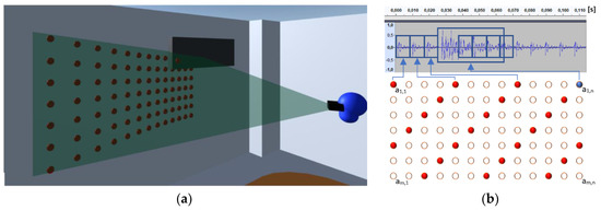
Figure 4.
Projected VAS. (a) Spawn positions of virtual audio sources. (b) S(t) acoustic output corresponding to (a), k = 4, in the first low-resolution image (T1).
When generating the PVAS acoustic output S(t), the array is accessed sequentially each . millisecond. The acoustic output prior to Resonance Audio’s processing (e.g., HRTF) corresponds to the expression
The array is accessed according to a linear congruential generator which verifies the Hull–Dobell theorem. Therefore, each element is called once per iteration of NxM elements, i.e., acoustic image. The equations used are
This algorithm is a low pass spatial filter of the acoustic image which provides a resolution-latency tradeoff schema. It firstly generates a fast, low-resolution acoustic image of the environment in seconds. The original acoustic image is then generated after seconds. This is meant to ease active sensing by reducing the motor-sensory loop latency. However, it assumes that orientation and mobility tasks are associated to relatively large elements, i.e., low spatial frequency data.
The original recordings have been weighted according to the size of each element and their relevance from the user perspective. Large background elements such as walls or ceiling are mapped to short, low-volume audio tracks. Conversely, tables, cupboards, etc., are mapped to longer, higher-volume audio tracks. This is oriented to reinforce the figure–background discrimination, to reduce the background noise, and to draw the user’s attention to relevant features of the environment even through a single acoustic pixel (Figure 4b). Finally, S(t) is converted to spatialized audio in the server with Resonance Audio (i.e., directivity of sound sources, reflections, occlusions, HRTF, etc.) and conveyed to the earphones.
The second sub-mode, Aural VAS (AVAS), spawns one virtual sound source per primitive which collides with a virtual area surrounding the user (Figure 3). The sound source is positioned at the closest point of the collided primitive. Each acoustic material is mapped to an AVAS audio track. These audio tracks are modulated according to the relative motion of the user in relation to the collided objects, which offers a rudimentary illusion of friction. Alternatively, non-modulated sounds are applied. These could be triggered when the user first collides with an object, or periodically while the virtual area overlaps with a nearby object. To avoid masking simultaneous sound sources, split-second audio tracks are reproduced periodically.
The third sub-mode, Flashlight, implements PVAS in combination with a speech synthesis module. In this mode, the virtual field of view of PVAS originates from the hand-held device, thus decoupling head movements from sound source spawning. This is meant to ease sound source localization, as well as promote faster and wider scanning movements.
By default, the virtual field of view is configured as a narrow beam to ease pointing accurately at a single element, similarly to Lazzus [10] and previous projects. All elements of the virtual scenario are tagged with a verbal description, which is reproduced when the user points to each object and taps the screen. The identification of an element through a verbal message, e.g., “table”, then conditions the induced perceptions and the development of mental representations of the scene.
All these modes include a filtering mask which allows the user to define a subset of perceivable objects of the virtual scenario, e.g., table, doors. Analogously to the audio track weighting, this feature was used to filter unnecessary information, and to help users in object–background discrimination. From the perspective of vision–acoustic sensory substitution, these methods favor figure–ground perception.
3.2. Experimental Procedures
In this work, three tests were conducted to validate the developed prototype. These tests were designed for normal-sighted, untrained individuals. The objective is to assess whether the subjects could decipher the data encoding of GbVAS, as well as to gather information regarding the development and usage of a mental representation of a scenario only perceivable through the prototype’s output.
The tests were carried out on flat surfaces of at least 40 × 20 m, such as soccer fields (Figure 5a). Each test has its own virtual scenario which was loaded within the field bounds (Figure 6).
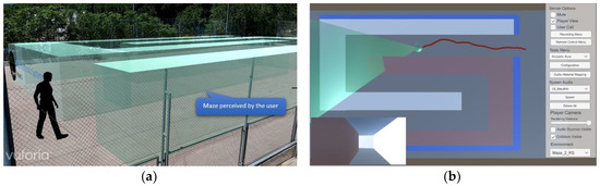
Figure 5.
Experiment design. (a) User in the soccer field with a loaded virtual scenario (b) Screenshot of the server’s graphical interface while the user moves through the scenario.
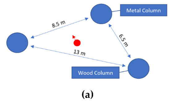
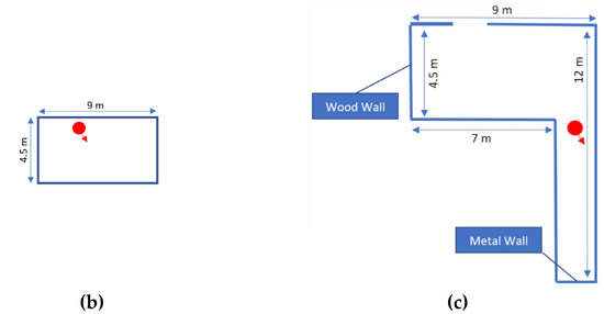
Figure 6.
Scenarios for tests 1 (a), 2 (b) and 3 (c). The default material is “brick”. The starting position and orientation are represented by a red dot and red arrow, respectively.
The first two tests consist of the free exploration of an unknown scenario (Figure 6a,b) within a time limit. The blindfolded subjects were told to move freely, make their own judgements about the audio spatial cues, and afterwards draw a sketch of how they perceived the scene. The sketch must be a bird’s eye view of the scene and must be drawn within a square representing the football field (scale reference).
No prior information of the scenario was provided as it could be used to decipher the data output. The time limit was fixed to three minutes, because in previous experiments there were no signs of major improvements in the output data decoding, nor in the knowledge of the scenario, after that time. Thereafter, the sketches are meant to provide data on the subjects’ perceptions through the sensory substitution algorithm, as well as any resulting survey/configurational knowledge of the scenario.
In the third test, subjects were shown a map of a virtual scenario (Figure 6c). Thereafter, they were blindfolded and immersed in the scenario at an unknown start position and were told to find the exit. The time limit was also three minutes.
The subjects received six minutes training in GbVAS’ usage through Tests 1 and 2. Also, subjects were familiarized with the scenario, which is meant to further improve output decoding. Subjects must then use that information to periodically estimate their position in relation to the exit, plan a route, and follow it.
Regarding the scenarios’ design, all three were meant to ease GbVAS’ output decoding, as well as evaluate orientation and mobility performance.
GbVAS partially uses natural data encoding, e.g., 3D location through HRTF, or the presence of physical elements and their material composition, by reproducing impact sounds. Starting from the premise that the subjects effectively and efficiently assimilate such data with no prior training, they must then search for the causes that trigger those stimuli. To that end, they need to observe the contingencies between body movements and the resulting changes in acoustic stimulation.
Taking this into consideration, the first scenario was designed as an open area with few elements of a reduced size, specifically three columns which are also intended to serve as landmarks (Figure 6a). This is meant to ease the discrimination of when an element enters or exits the GbVAS virtual area, i.e., the identification of spatial boundaries. Thereafter, the subjects are free to make estimations about the range of such boundaries. Given that the scenario is unknown, this serves to test if the kinesthetic sense is able to assimilate GbVAS’ virtual area and disentangle its shape from those of the elements in the vicinity.
The second scenario is a rectangular room of 4.5 × 9 m (Figure 6b). In Test 1, the users were provided with basic cues of the data output, emphasizing whether there is an element or not. In this closed area, minimum perception and consequent mobility tasks can be assumed if the subjects move without leaving the room.
Finally, the third scenario was intended to be simple, with several easy to perceive elements used as landmarks. In line with this, it was designed as an L-shaped room with different wall materials. If subjects can leave the room through the exit, it would mean that they are able to decode the prototype’s output to a degree that allows it to be used for basic orientation and mobility tasks.
In addition to the sketches, the motion data of the subjects were recorded in the three tests. Specifically, the subjects’ head pose was measured and registered with ARCore each 20 ms. Therefore, centimeter-accuracy representations of the route followed are available for further analysis (e.g., Figure 7a), in addition to split-second reactions to environmental features.

Figure 7.
Screenshots of the route followed by a test subject in tests 1 (a) and 3 (b).
For these experiments we had a total of sixteen subjects, which were divided equally into groups A and B (Table 1). Both groups undertook the three tests, but with different GbVAS configurations. As stated in Table 1, Group A only used PVAS while PVAS and AVAS were used simultaneously by Group B.

Table 1.
Geometric-based virtual acoustic space (GbVAS) configuration for groups A and B. PVAS’ matrix of stereopixels (MxN), randomizer (K), angle of view, spawning period (TS) and detection distance. AVAS’ mode of operation and detection range (radius).
PVAS configuration was set as a compromise between field of view, resolution and feedback delay, optimized after previous tests. Firstly, the feedback delay was set to its minimum value. In this regard, the current implementation introduces jitter in Ts, i.e., minimum motor-sensory loop delay, with a standard deviation of 9 ms. Thereafter, we defined 20 ms as the minimum threshold of Ts which guarantees acceptable quality of the output signal. The acoustic image resolution was then fixed to 13 × 7 within a field of view of 30° and 50° in the vertical and horizontal axis, respectively. With this setup, 27% of the original acoustic image resolution is provided in half a second.
On the other hand, AVAS was configured as non-modulated periodic pulses which are triggered in a virtual area within arms’ reach. Again, this configuration was considered optimal after previous experiments and according to the final users’ suggestions.
4. Results
Several common user behaviors were observed throughout the experiments carried out, most of which are summarized in Figure 8 and Figure 9.
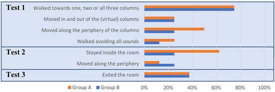
Figure 8.
Common subject behavior.
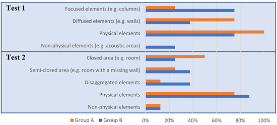
Figure 9.
Common features of the scenarios described and drawn by the subjects.
In the first test, 75% of the subjects walked to one, two or all three columns sequentially, and stopped at a fixed distance. Thereafter, most of them walked in and out of the columns periodically (25%, e.g., Figure 7a) or moved along their periphery (37.5%), allegedly calibrating its range. Conversely, 18.75% simply avoided all sound-triggering areas. In the sketches, Group A showed a tendency to identify the columns as 5–6 m long walls; conversely, Group B identified them as rectangular-shaped areas with a similar size to the columns.
In the second test, nearly half of the subjects remained inside the room. Of the remaining subjects, three of them exited the room and moved along its periphery. Approximately one third of the subjects identified the room as a closed area, while most of the other subjects drew perpendicular walls or several disaggregated elements which left open spaces. One of the test subjects was unable to draw anything (Group A).
In the third test, 37.5% of the subjects of both groups successfully left the room (e.g., Figure 7b), and another one missed the exit by approximately a meter. Outside of the test methodology, these subjects accurately described the starting point and route followed. As an example, we include a drawing made by one of Group A’s subjects (Figure 10). Most of the remaining subjects slid repeatedly through the walls, while some of them were able to roughly describe the route followed until a point at which they lost key position references.
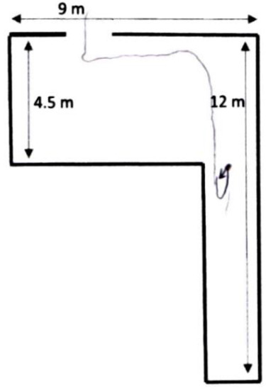
Figure 10.
Subject A1′s drawing of the starting point and route followed in Test 1.
Finally, all users described their experience with the prototype. Most of them found PVAS intuitive and easy to use. Particularly, the subjects that completed successfully Test 3 seemed to correctly decode PVAS’ output. One of them even reported a delay in head movements and acoustic stimuli which matches with T2 (Section 3.1.3). As for AVAS, approximately half of Group B interpreted the sound pulses, which signal a collision, as orientation cues. Coherently, they tended to be lured towards nearby elements, and some of them even described most of the scenarios’ elements as areas which triggered characteristic sounds (material–audio track mapping) instead of solid volumes. However, an understanding of AVAS operation has a positive impact on navigation performance. In line with this, two subjects of Group B that failed to complete Test 3 repeated and completed it after a brief explanation of how AVAS works. One of them used AVAS to move at a fixed distance from the room walls, while the other used it to avoid them.
5. Discussion
The prototype VES has been conceived and developed as a versatile tool which allows the implement and testing of non-visual human-machine interfaces for BVI navigation in both virtual and real scenarios. The tests described in the previous section have validated its potential in this regard. Also, the tests conducted provide a few cues about GbVAS’ effect on orientation and mobility tasks. Nevertheless, a more detailed analysis of a more extensive population of both normal-sighted and BVI individuals is required.
Coherently with the experiments’ design, most of the test subjects identified regions in which acoustic cues were generated, as well as GbVAS’ virtual areas which moved according to head movements. After only six minutes training, they were able to use the prototype to perceive key features of the environment. The usage of natural data encoding is considered to play a key role in this respect.
Nevertheless, the spatial boundaries of nearby elements and GbVAS virtual areas tended to be distorted when there is no prior knowledge on the prototype’s output nor the scenario.
In Test 1, Group A tended to overestimate the size of the columns. This is probably due to an underestimation of PVAS’ field of view and lack of training, as an object’s size could be inferred from the acoustic image. However, these results did not occur in a known environment (Test 3). On the other hand, Group B tended to correctly estimate the columns’ size, probably because of a redundancy in PVAS and AVAS output.
However, in Test 2 Group B performed poorly compared with Group A. Again, they tended to interpret AVAS output as heading cues, and were therefore lured inside the walls. Outside of the experimental setup, experimented users of GbVAS used AVAS to improve mobility performance. In future experiments, it will be tested whether the subjects’ navigation behavior changes if they are provided with a few notions of AVAS operation.
Another key result of these experiments is that PVAS and AVAS could be used at the same time by Group B. Therefore, the required bandwidth and cognitive load was low enough to avoid overloading the user. For future research, it would also be important to test whether VES can be used by the targeted public without masking key auditory feedback from the actual environment.
These results also account for the importance of bias, as the low resolution of VES does not allow the identification of features which were drawn in the sketches, e.g., the shapes of the columns in Test 1. Even simple messages can condition perception, and the development of a mental representation of the environment. Therefore, this highlights the potential of verbal interfaces in this regard.
Finally, the feedback provided by the subjects can be summarized in two main points. Firstly, a detailed explanation on GbVAS operation is needed, although some of the users were able to decode the data output by themselves through a trial-and-error process. Secondly, AVAS data-encoding proved to be difficult to assimilate, although its range of effect effectively complemented PVAS once the user became familiar with it. Therefore, this human–machine interface algorithm might be further enhanced with novel spatial data encoding while maintaining AVAS’s virtual area.
6. Conclusions
The VES prototype described throughout this document has been assessed as a versatile platform to test non-visual human–machine interfaces for BVI navigation in indoor and outdoor, and real and virtual environments. Overall, it is a software application running in commodity devices, which eases its usage for experimentation purposes, and might encourage further development in the field.
The current output configuration integrates previous and novel sensory substitution algorithms. Our approach involves the usage of natural data-encoding of human perception, with an emphasis placed on distance perception of hearing and remote touch. In the conducted tests, VES showed promising results in orientation and mobility tasks after only six minutes training. In this regard, ARCore motion capture provided key and objective test data, from the route followed by users to split-second reactions to the elements in their path. This includes the delay between an obstacle warning and the subsequent changes in walking speed, or the correspondence between head movements, which trigger spatial-related data, and the route followed by the user.
Author Contributions
Conceptualization, S.R. and A.A.; methodology, S.R.; software, S.R.; validation, S.R. and A.A.; formal analysis, S.R.; investigation, S.R.; resources, A.A.; data curation, S.R.; writing—Original draft preparation, S.R.; writing—Review and editing, A.A.; visualization, S.R.; supervision, A.A. All authors have read and agreed to the published version of the manuscript.
Funding
This research received no external funding.
Acknowledgments
The authors also want to thank Francisco Tirado and Roberto Rodriguez-Zurrunero from B105 Electronic Systems Lab, for their comments that greatly improved the manuscript.
Conflicts of Interest
The authors declare no conflict of interest.
References
- Ahmetovic, D.; Gleason, C.; Ruan, C.; Kitani, K. NavCog: A Navigational Cognitive Assistant for the Blind. In Proceedings of the 18th International Conference on Human-Computer Interaction with Mobile Devices and Services (MobileHCI ’16), Florence, Italy, 6–9 September 2016; pp. 90–99. [Google Scholar]
- Seeing, A.I. Talking Camera App for Those with a Visual Impairment. Available online: https://www.microsoft.com/en-us/seeing-ai/ (accessed on 9 January 2020).
- Real, S.; Araujo, A. Navigation Systems for the Blind and Visually Impaired: Past Work, Challenges, and Open Problems. Sensors 2019, 19, 3404. [Google Scholar] [CrossRef] [PubMed]
- Montello, D.; Giudice, N.A. Navigating without vision: Principles of blind spatial cognition. In Handbook of Behavioral and Cognitive Geography; Edward Elgar Publishing: Cheltenham, UK; Northampton, MA, USA, 2018; pp. 260–288. [Google Scholar]
- Schinazi, V.R.; Thrash, T.; Chebat, D.R. Spatial navigation by congenitally blind individuals. Wiley Interdiscip. Rev. Cogn. Sci. 2016, 7, 37–58. [Google Scholar] [CrossRef] [PubMed]
- WayFindr. Available online: https://www.wayfindr.net/ (accessed on 9 January 2020).
- NaviLens-Smartphone Application. Available online: https://www.navilens.com/ (accessed on 9 January 2020).
- Loomis, J.M.; Golledge, R.G.; Klatzky, R.L.; Marston, J.R. Assisting wayfinding in visually impaired travelers. In Applied Spatial Cognition: From Research to Cognitive Technology; Lawrence Erlbaum Associates, Inc.: Mahwah, NJ, USA, 2007; pp. 179–203. [Google Scholar]
- Carrasco, E.; Loyo, E.; Otaegui, O.; Fösleitner, C.; Dubielzig, M.; Olmedo, R.; Wasserburger, W.; Spiller, J. ARGUS Autonomous Navigation System for People with Visual Impairments. In Lecture Notes in Computer Science (Including Subseries Lecture Notes in Artificial Intelligence and Lecture Notes in Bioinformatics); Springer: Berlin/Heidelberg, Germany, 2014; Volume 8548, pp. 100–107. [Google Scholar]
- Lazzus. Available online: http://www.lazzus.com/en/ (accessed on 29 July 2019).
- Hub, A. Precise Indoor and Outdoor Navigation for the Blind and Visually Impaired Using Augmented Maps and the TANIA System. In Proceedings of the 9th International Conference on Low Vision, Vision 2008, Montreal, QC, Canada, 7–11 July 2008; pp. 2–5. [Google Scholar]
- Spiers, A.J.; Dollar, A.M. Design and evaluation of shape-changing haptic interfaces for pedestrian navigation assistance. IEEE Trans. Haptics 2017, 10, 17–28. [Google Scholar] [CrossRef] [PubMed]
- Kaczmarek, K.; Bach-y-Rita, P.; Tompkins, W.J.; Webster, J.G. A tactile vision-substitution system for the blind: Computer-controlled partial image sequencing. IEEE Trans. Biomed. Eng. 1985, 32, 602–608. [Google Scholar] [CrossRef] [PubMed]
- Meijer, P.B.L. An Experimental System for Auditory Image Representations. IEEE Trans. Biomed. Eng. 1992, 39, 112–121. [Google Scholar] [CrossRef] [PubMed]
- Grant, P.; Spencer, L.; Arnoldussen, A.; Hogle, R.; Nau, A.; Szlyk, J.; Nussdorf, J.; Fletcher, D.C.; Gordon, K.; Seiple, W. The Functional Performance of the BrainPort V100 Device in Persons Who Are Profoundly Blind. J. Vis. Impair. Blind. 2016, 110, 77–89. [Google Scholar] [CrossRef]
- Ward, J.; Meijer, P. Visual experiences in the blind induced by an auditory sensory substitution device. Conscious. Cogn. 2010, 19, 492–500. [Google Scholar] [CrossRef] [PubMed]
- Loomis, J.M.; Klatzky, R.L.; Giudice, N.A. Sensory substitution of vision: Importance of perceptual and cognitive processing. In Assistive Technology for Blindness and Low Vision; CRC Press: Boca Ratón, FL, USA, 2012; pp. 162–191. [Google Scholar]
- Gonzalez-Mora, J.L.; Rodriguez-Hernaindez, A.F.; Burunat, E.; Martin, F.; Castellano, M.A. Seeing the world by hearing: Virtual Acoustic Space (VAS) a new space perception system for blind people. In Proceedings of the 2006 2nd International Conference on Information & Communication Technologies, Damascus, Syria, 24–28 April 2006; Volume 1, pp. 837–842. [Google Scholar]
- González-Mora, J.L.; R Odríguez-Hernández, A.; Rodríguez-Ramos, L.F.; Dfaz-Saco, L.; Sosa, N. Development of a new space perception system for blind people, based on the creation of a virtual acoustic space. In Engineering Applications of Bio-Inspired Artificial Neural Networks, Proceedings of the International Work-Conference on Artificial Neural Networks, Alicante, Spain, 2–4 June 1999; Lecture Notes Computer Science; Springer: Berlin/Heidelberg, Germany, 1999; Volume 1607, pp. 321–330. [Google Scholar]
- Cassinelli, A.; Reynolds, C.; Ishikawa, M. Augmenting spatial awareness with haptic radar. In Proceedings of the 2006 10th IEEE International Symposium on Wearable Computers, Montreux, Switzerland, 11–14 October 2006; pp. 61–64. [Google Scholar]
- Meers, S.; Ward, K. A vision system for providing 3D perception of the environment via transcutaneous electro-neural stimulation. In Proceedings of the Eighth International Conference on Information Visualisation 2004 (IV 2004), London, UK, 16 July 2004. [Google Scholar]
- Lahav, O.; Gedalevitz, H.; Battersby, S.; Brown, D.; Evett, L.; Merritt, P. Virtual environment navigation with look-around mode to explore new real spaces by people who are blind. Disabil. Rehabil. 2018, 40, 1072–1084. [Google Scholar] [CrossRef] [PubMed]
- Cobo, A.; Guerrón, N.E.; Martín, C.; del Pozo, F.; Serrano, J.J. Differences between blind people’s cognitive maps after proximity and distant exploration of virtual environments. Comput. Hum. Behav. 2017, 77, 294–308. [Google Scholar] [CrossRef]
- Zerroug, A.; Cassinelli, A.; Ishikawa, M. Virtual Haptic Radar. In Proceedings of the ACM SIGGRAPH ASIA 2009 Sketches, Yokohama, Japan, 16–19 December 2009. [Google Scholar]
- Massiceti, D.; Hicks, S.L.; van Rheede, J.J. Stereosonic Vision: Exploring Visual-to-Auditory Sensory Substitution Mappings in an Immersive Virtual Reality Navigation Paradigm. PLoS ONE 2018, 13, e0199389. [Google Scholar] [CrossRef] [PubMed]
- Jafri, R.; Campos, R.L.; Ali, S.A.; Arabnia, H.R. Visual and Infrared Sensor Data-Based Obstacle Detection for the Visually Impaired Using the Google Project Tango Tablet Development Kit and the Unity Engine. IEEE Access 2017, 6, 443–454. [Google Scholar] [CrossRef]
- Zhang, X.; Yao, X.; Zhu, Y.; Hu, F. An ARCore based user centric assistive navigation system for visually impaired people. Appl. Sci. 2019, 9, 989. [Google Scholar] [CrossRef]
- Electronic Travel Aids: New Directions for Research; National Academies Press: Washington, DC, USA, 1986; ISBN 978-0-309-07791-0.
- Schinazi, V. Representing Space: The Development Content and Accuracy of Mental Representations by the Blind and Visually Impaired; University College London: London, UK, 2008. [Google Scholar]
- Maidenbaum, S.; Abboud, S.; Amedi, A. Sensory substitution: Closing the gap between basic research and widespread practical visual rehabilitation. Neurosci. Biobehav. Rev. 2014, 41, 3–15. [Google Scholar] [CrossRef] [PubMed]
- Haigh, A.; Brown, D.J.; Meijer, P.; Proulx, M.J. How well do you see what you hear? The acuity of visual-to-auditory sensory substitution. Front. Psychol. 2013, 4, 330. [Google Scholar] [CrossRef] [PubMed]
- Sampaio, E.; Maris, S.; Bach-y-Rita, P. Brain plasticity: Visual acuity of blind persons via the tongue. Brain Res. 2001, 908, 204–207. [Google Scholar] [CrossRef]
- Thinus-Blanc, C.; Gaunet, F. Representation of space in blind persons: Vision as a spatial sense? Psychol. Bull. 1997, 121, 20–42. [Google Scholar] [CrossRef] [PubMed]
© 2020 by the authors. Licensee MDPI, Basel, Switzerland. This article is an open access article distributed under the terms and conditions of the Creative Commons Attribution (CC BY) license (http://creativecommons.org/licenses/by/4.0/).