1. Introduction
For some people with limb problems, it is impossible to have accurate control over hand movement. Common assistive devices for them include a head-controlled control stick-shaped device, mouth-held stick device, and mouth-controlled blow device. However, these assistive tools are not sanitary, comfortable, or convenient because users have to wear or touch some mechanical sensing devices [
1,
2,
3]. Given the inconvenience of the existing assistive systems for the disabled, a system, featuring a combination of computer-based vision technology and movement detection, was developed [
4,
5,
6]. Based on information about the head, it is a household control system for the disabled, and includes color segmentation and head recognition [
7].
When the head is held straight without any deflection, the eyes are almost on the same horizontal line; when the head tilts right or left, the angle between the line linking the canthi of the eyes and the horizontal line changes. Therefore, a tilt of the head can be judged according to the angle. There are many algorithms and configurations for head-control devices and sensing human activities [
8]. In an image-type head gesture control device, a CCD (charge-coupled device) camera is used to detect the position of the head without influence from the background. Head movements can also be linked to the position of the cursor on a screen, and the user can control the cursor with his head [
9]. Canal developed a system that deals with dynamic gestures, such as waving or nodding, that were recognized using a dynamic time-warping approach based on gesture-specific features computed from depth maps [
10]. Lee developed an interface used by severely disabled people who can only move their heads and have difficulties using a joystick, chin stick, and voice- or breath-sensor assistive devices [
11]. Terven focused on detecting head-nodding as a relatively simple, non-verbal communication modality because of its significance as a gesture displayed during social interactions [
12]. Madeo outlined an approach to automating G-unit and gesture phase segmentation. Their approach treated the segmentation question as a classification problem and used a vector machine with different strategies to solve it [
13]. Yi proposed an intelligent wheelchair system based on sEMG (surface electromyography), head gestures, and a feature extraction algorithm based on an improved wavelet packet and sample entropy [
14]. Pisharady pointed out the need to consider many measures together with the recognition accuracy of the algorithm to predict its success in real-world applications [
15]. Lalithamani used a single-web camera as the input device to recognize hand gestures. Some of these gestures included controlling the mouse cursor, clicking actions, and a few shortcuts for opening specific applications [
16]. Halim proposed a method to detect gestures stored in a dictionary with an accuracy of 91% and could define and add custom-made gestures [
17].
This study develops a machine vision system. Equipped with a laptop and connected with numeric head-controlled software, it is transformed into a sound-generating system suitable for the disabled. With the system, users can change their head pose, and, using the program code, the change will be converted into acoustic signals to generate sound. This study thus establishes a numeric human–machine interface to provide a more flexible and diverse interface for users.
The rest of this paper is organized as follows: in
Section 2, the proposed conceptual design is described in detail. User testing is described in
Section 3.
Section 4 presents the experimental results and the discussion. Finally, the conclusions are given in
Section 5.
2. Conceptual Design
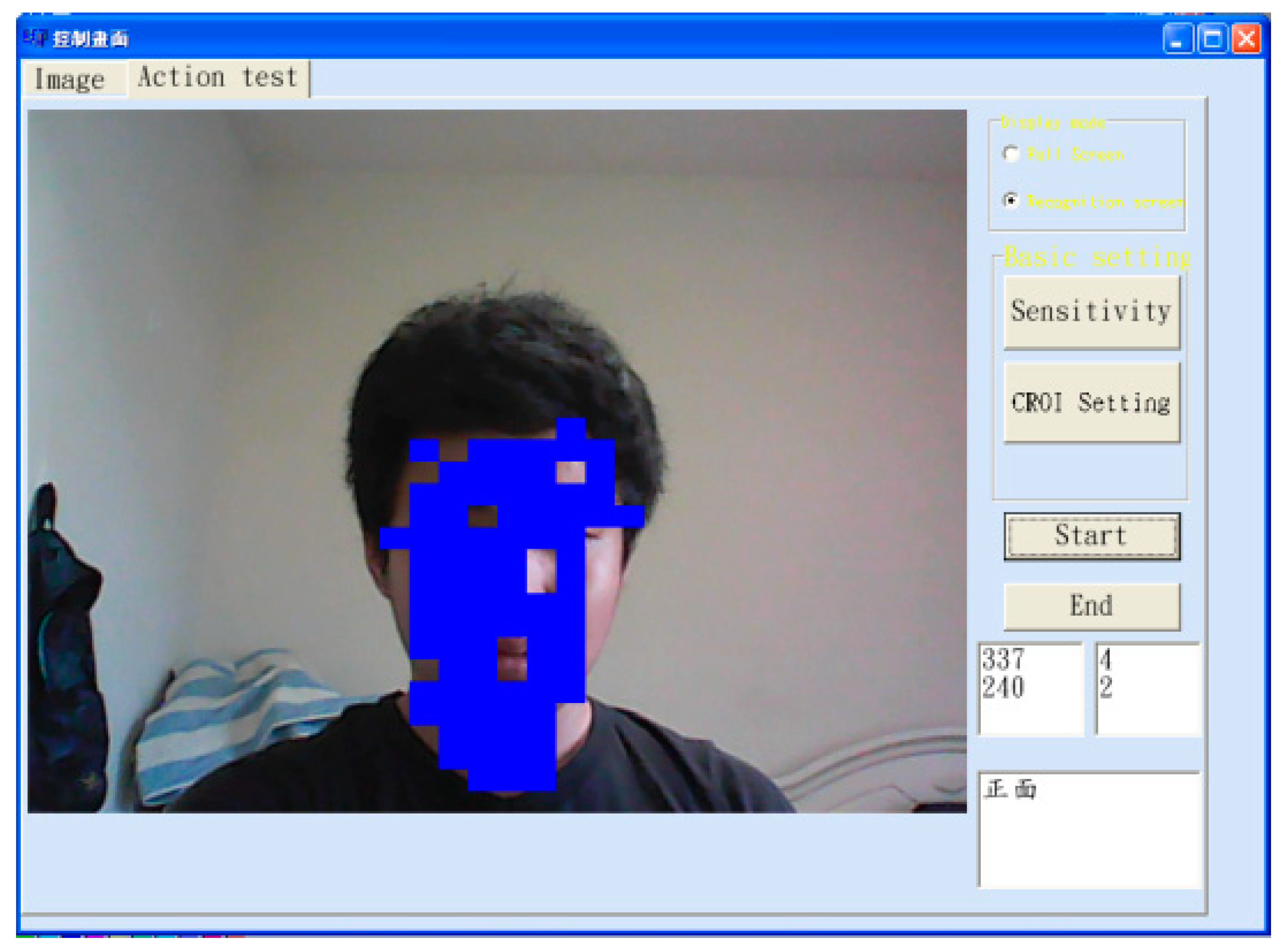
This research used image-sensing equipment to detect head rotation position information and complete the comparison of head posture changes. Due to the use of a telescope lens, the user does not need to be very close to the camera to get a clear head image, which can save processing time for face or head detection. A personal computer and a C++ object-oriented development platform were used for program development. In Microsoft Windows, the user’s control speed was improved with simple operation methods. In the aspect of searching for the target object (the head), first we adjusted the proper skin color threshold value for image input and, at the same time, calculated the coordinates of the center of the head (
Figure 1).
where
RXY,
GXY, and
BXY are the values of RGB components.
Rmax,
Rmin,
Gmax,
Gmin,
Bmax, and
Bmin are the upper and lower values of RGB channels in the skin image.
g(x,y) is the new gray level. Equation (1) assumed that in the RGB space skin color is cuboid, which was a simplification.
We then activated the dynamic image search method and set up a dynamic image search frame by taking the coordinates of the barycenter point of the skin color part in the image (
Figure 1) as the initial value. After finding the barycenter point (
Ux, Uy) in the image, the system proceeded to the validation process.
where
xf and
yf are the coordinates of the points of the skin color part in the image.
a is the number of pixels in the skin image.
The user had to move along a specific path, according to the coordinates indicated by the system, to confirm that the system had retrieved the feature object. If not, the system must return to the initial setting to retrieve the feature object again. According to the head direction judgment rule of this study, the skin color barycenter point of the front-side image was taken as the datum point [
18].
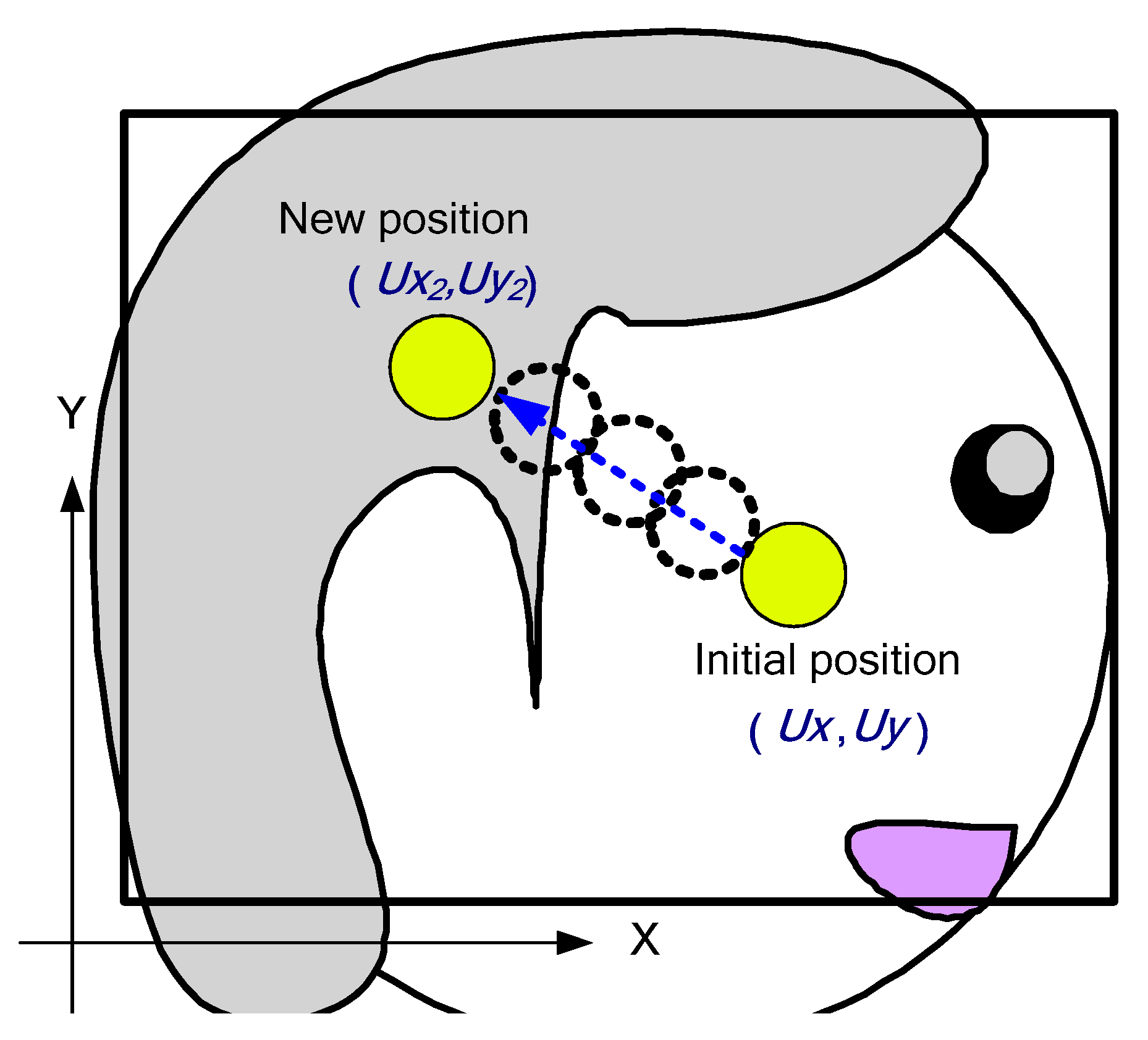
When the head moved, the system recorded the position of skin color points and then judged if the head moved upwards or downwards, according to the change in the position of the skin color points. If the number of skin color points after head movement was smaller than that of the front-side position, the result would be taken as an additional condition for subsequent direction judgment. The barycenter after object movement was then sought in the dynamic image search box. The relevance between the barycenter point after the movement and the new datum point (
Ux2, Uy2) was obtained in the judgment equation, and its corresponding status was displayed (
Figure 2) [
19].
The total number of skin color highlights of the front side of the head was
Ua, while
Ua2 was the total number of skin color highlights after head movement. When
Ua2 was smaller than
Ua, the judgment parameter
Uc was set as 0; otherwise it was set as 1.
Here (
Ux, Uy) are, respectively, the components
x and
y of the datum point; (
Ux2, Uy2) are the respective components
x and
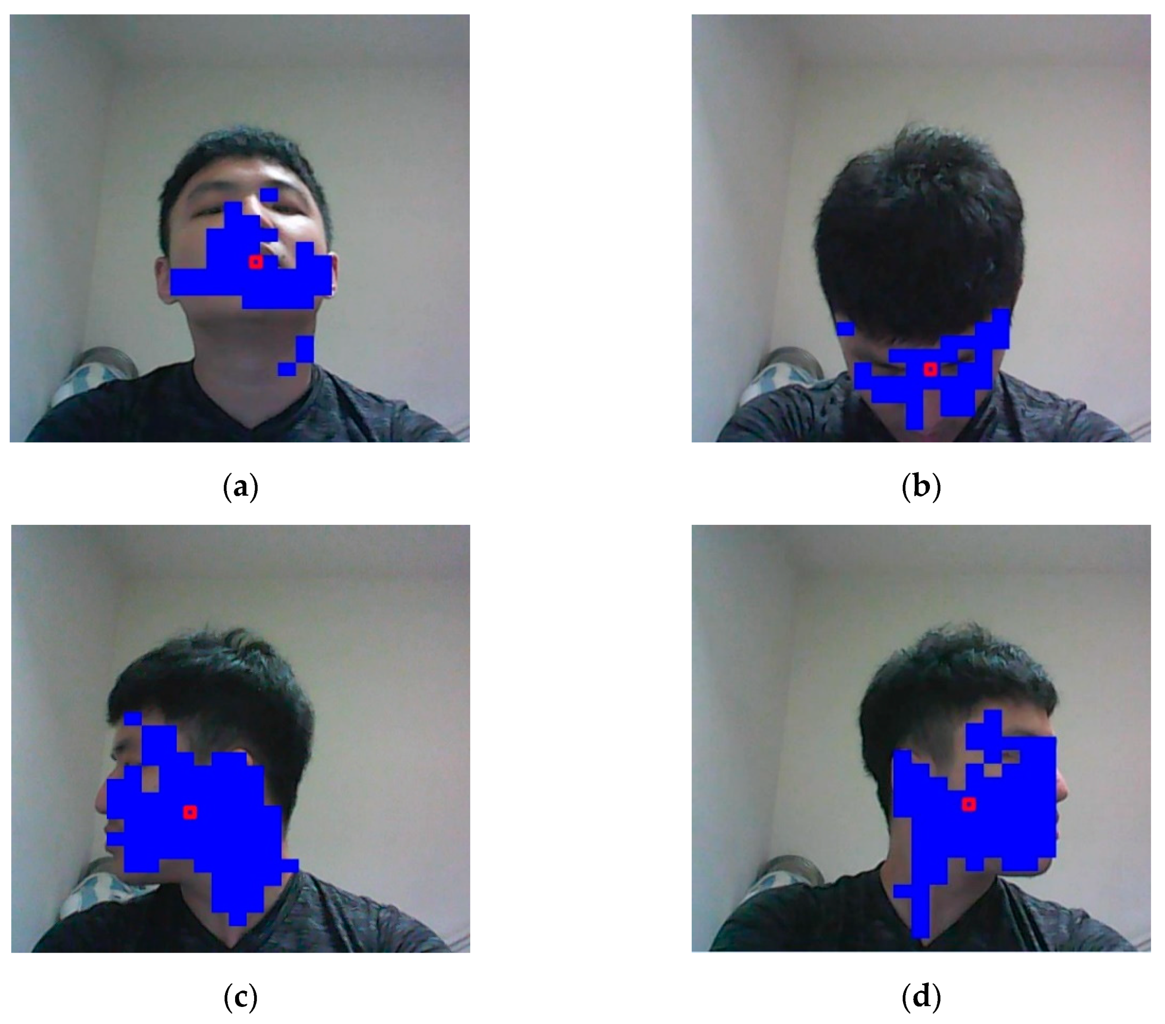
y of the barycenter coordinates of the image after its movement. When the head was raised or lowered, due to light reflection, many pixels belonging to the face were unrecognized as skin, so the system must have had a fault-tolerant design. After the above-mentioned judgment of head direction, the system was able to judge the upward, downward, leftward, and rightward movements of the head. In
Figure 3, the blue parts show the facial positions traced by the system. The background was normally the wall of an office room. It can be defined as follows:
where
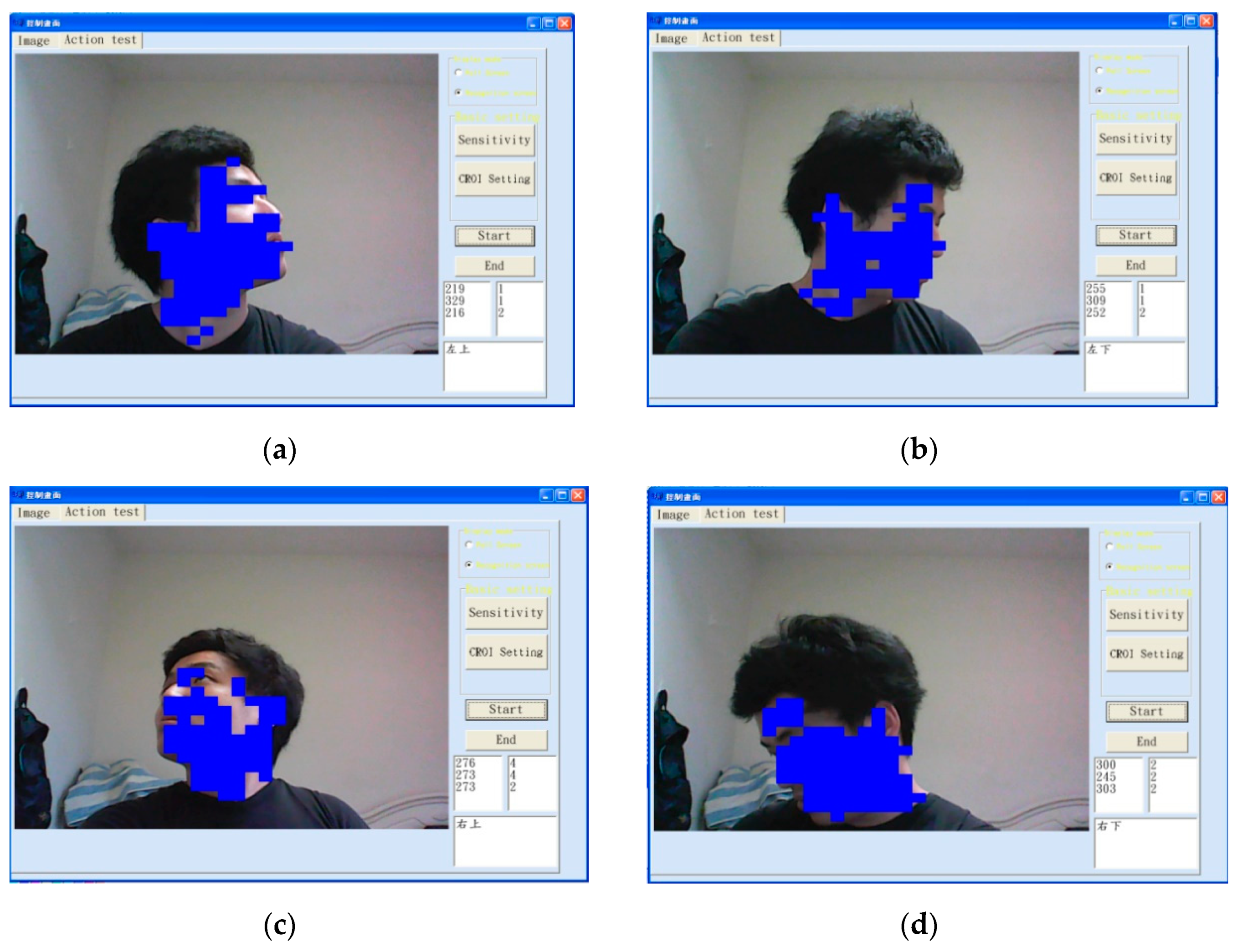
w, v are the adjustment parameters. It could be extended to judge the right-upward, right-downward, left-upward, and left-downward movements of the head (
Figure 4). For initialization, we usually set
w = 20 and
v = 10. The skin color area would be much larger when the neck was visible. As the head moved downwards, the area would be smaller. The adjustment parameters could be applied here to solve this problem. The situations in
Figure 4 did not show significant differences in blue-area size, but through the innovative judgment method of this system, head movement in eight directions could still be correctly judged.
3. User Testing
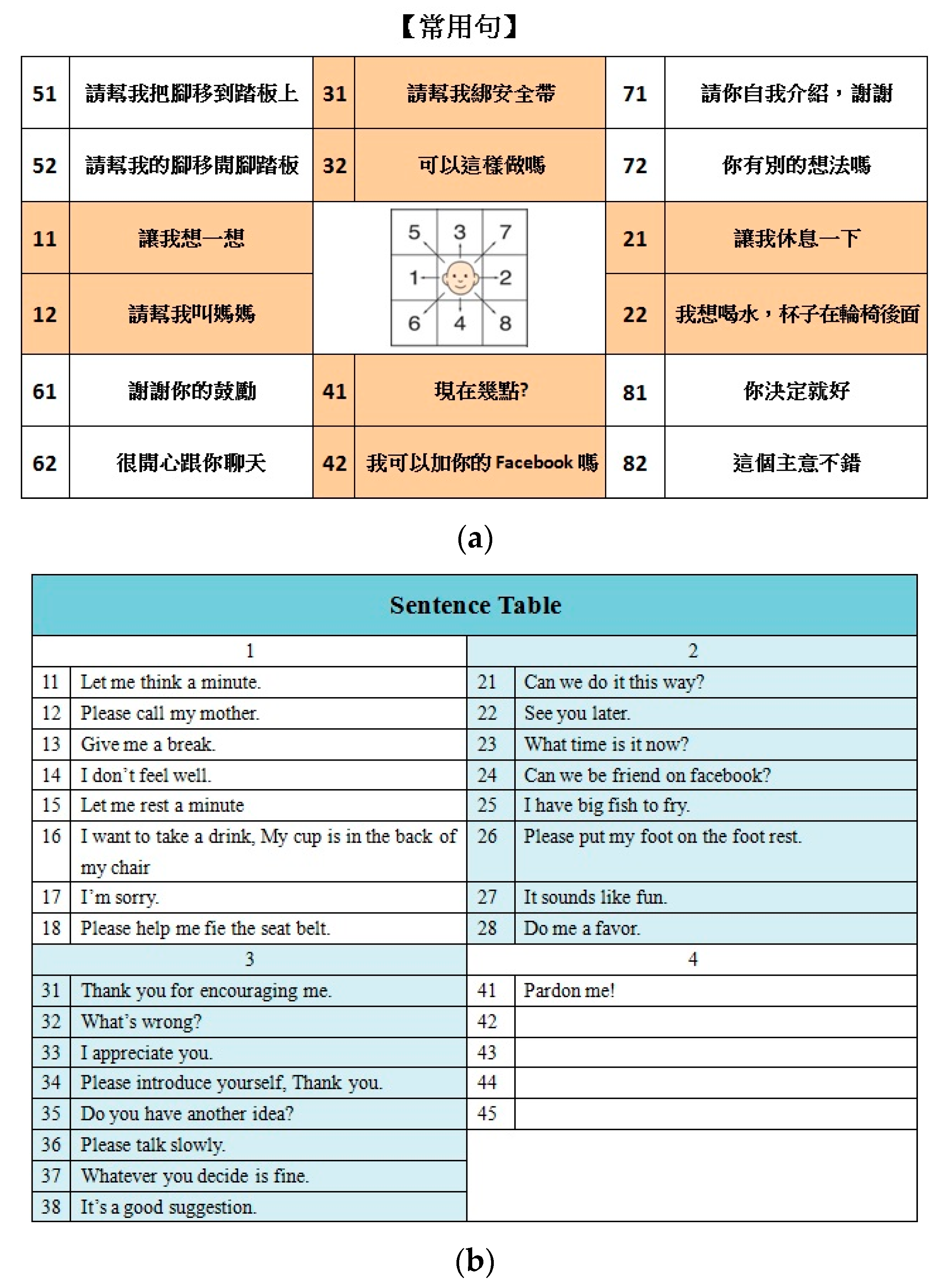
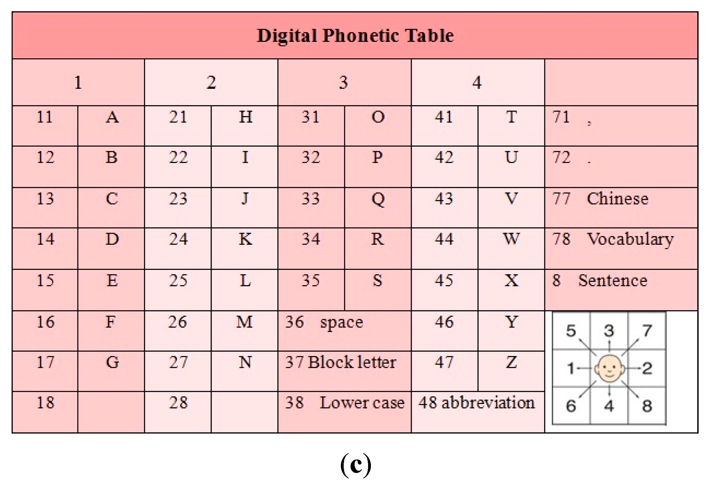
Figure 5 shows an example of a Chinese sentence table [
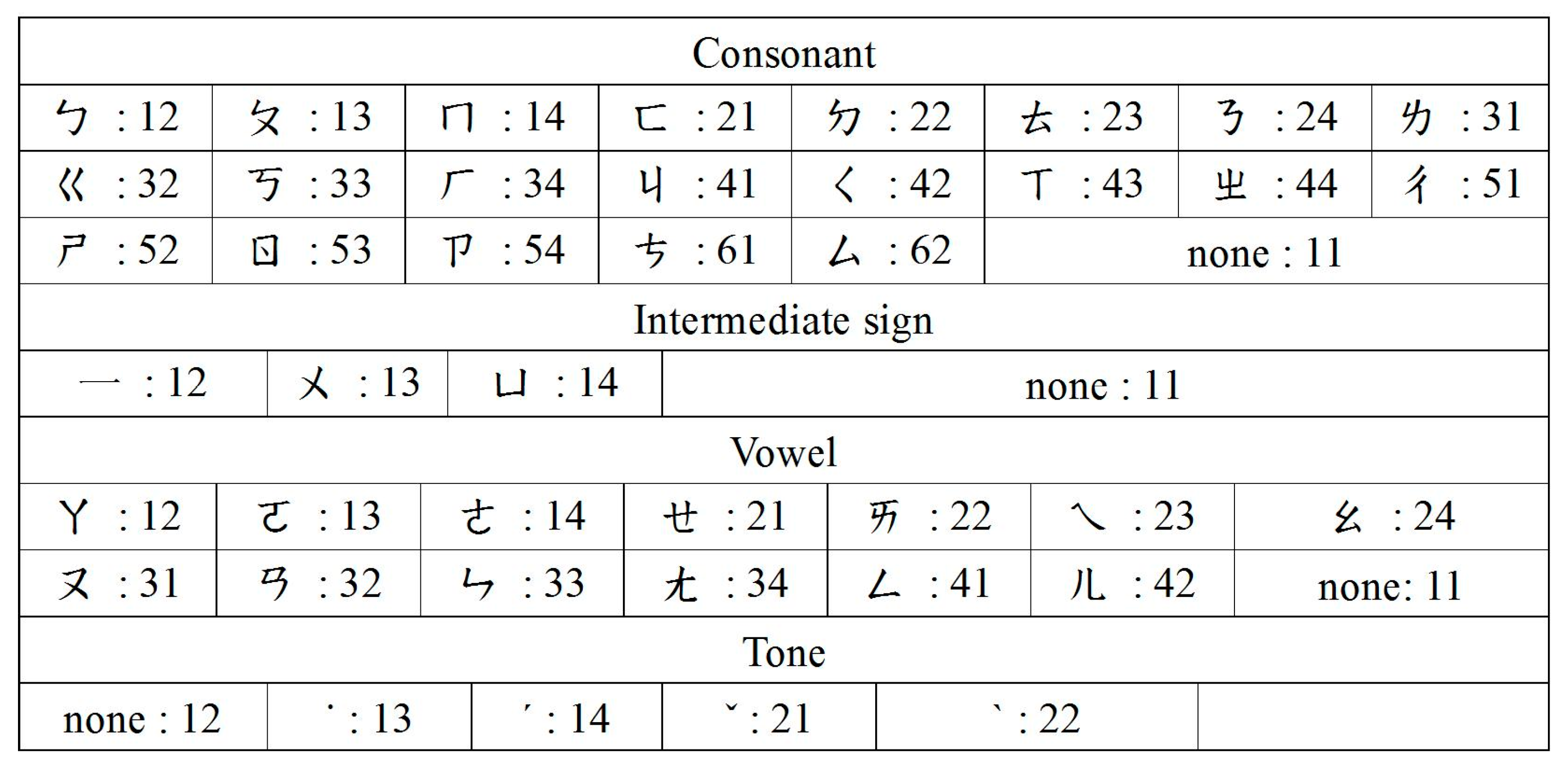
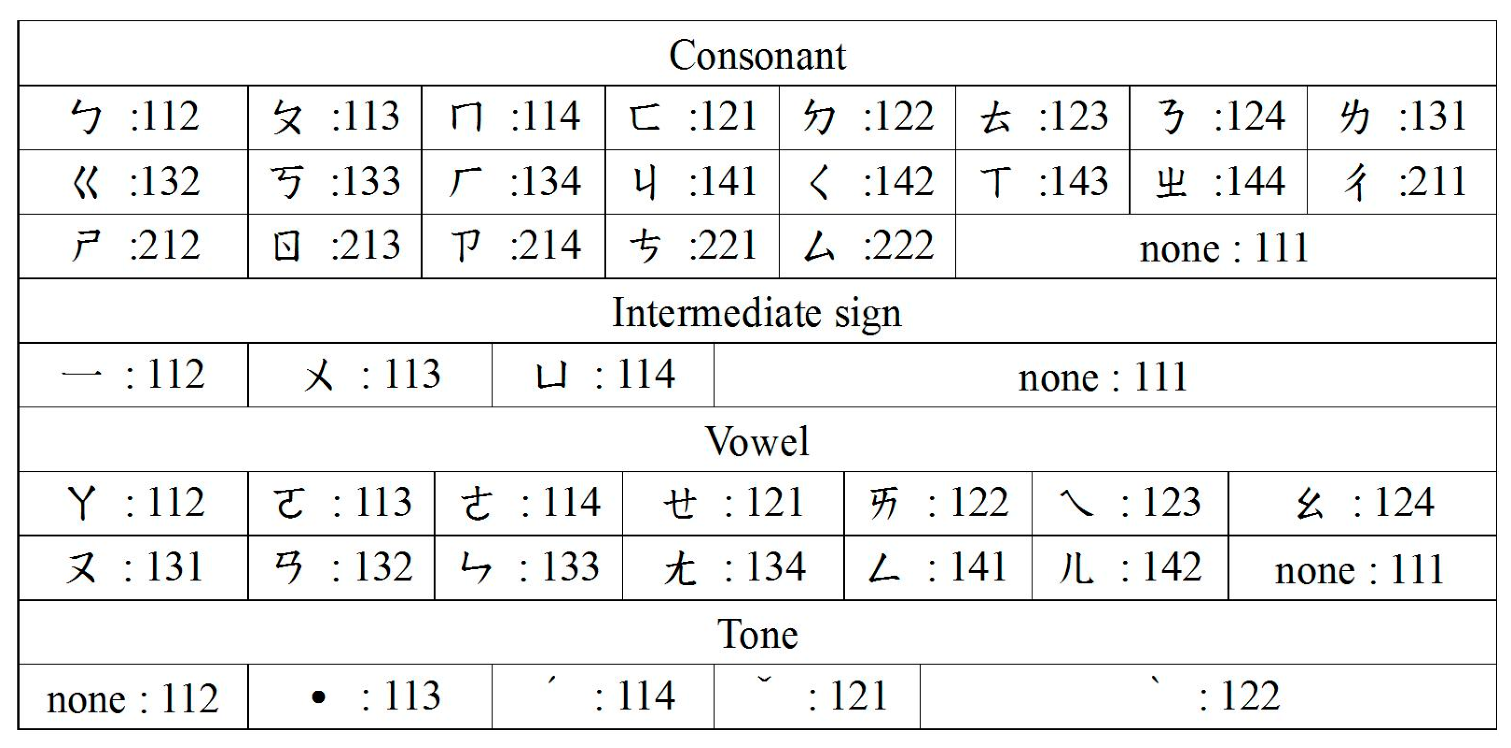
20] frequently used in numeric human–machine interfaces. This research established two different Chinese code tables. For the disabled, digitalized Chinese phonetic alphabet tables are far more complicated and difficult to use than the English ones. The selection of the eight-direction model or the four-direction model would lead users to the two-numeric-codes procedure (
Figure 6) or the three-numeric-codes procedure (
Figure 7). The rules in Chinese reduced the problems that users had with the flexible phonetic alphabet. It could obtain eight postures of up, down, left, right, top right, bottom right, top left, and bottom left, then converted the feature point position result detected by the system for judging. For example, the English letter “E” has a two numeric code of 15. The user needed to complete the first head-action selection “1” and then the second head-action selection “5” to complete the input of the English letter “E”. The system did not need an extra activation command, so the user moved their head to select a sentence. When a command was made by mistake, the user needed only to shake his head and try again.
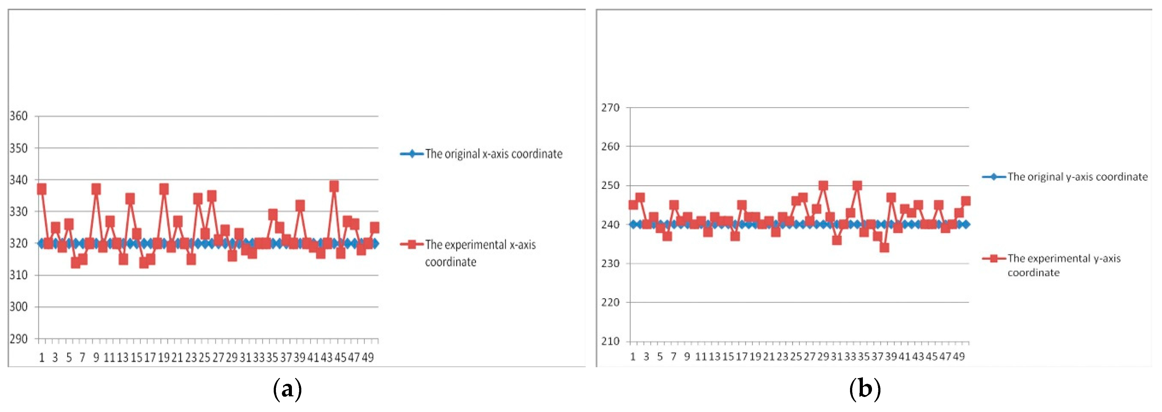
The test results of computing position stability of this study are shown in
Figure 8. For the analysis of the barycenter algorithm, the experiment placed the black center point in the center of the image. The actual position coordinates in the image captured by the camera were compared with barycenter position coordinates. The experiment was repeated 50 times, and, according to
Figure 8, the accuracy of the barycenter algorithm was high; hence, the human–machine interface of the system resulted in a low probability of misjudgment and was convenient to operate.
This study included statistical analysis of the accuracy of the head-pose-detection system. Through the conversion of the eight poses (up, down, left, right, upper right, lower right, upper left, and lower left), the feature point positions detected by the system and the judgment-based positions were observed. The eight-direction and four-direction systems were both tested 80 times under three states: (1) finish one movement within 10 s; (2) finish one movement within 5 s; and (3) finish one movement within 2 s. The results are shown in
Figure 9 and
Figure 10.
The scope of the direction judgment in the experiment was as follows: up, y < 220; down, y > 370; left, x > 375; right, x < 310; lower right, x < 310 and y > 370; upper right, x < 310 and y < 220; lower left, x>375 and y > 370; upper left, x < 310 and y < 220; x and y are the respective horizontal and vertical coordinate points of the barycenter. According to the statistical results, the accuracy of one movement in the eight directions within 10 s was 100%, 97.5% within 5 s, and 92.5% within 2 s. The accuracy of one movement in the four directions was 100% within 10 s and 5s, and 97.5% within 2 s. This demonstrated that if users required to finish a head turn within 2 s with the system’s help, there might be errors due to inadequate time for procedural judgment. Nonetheless, the accuracy was still over 90%. Therefore, the system was quite stable.
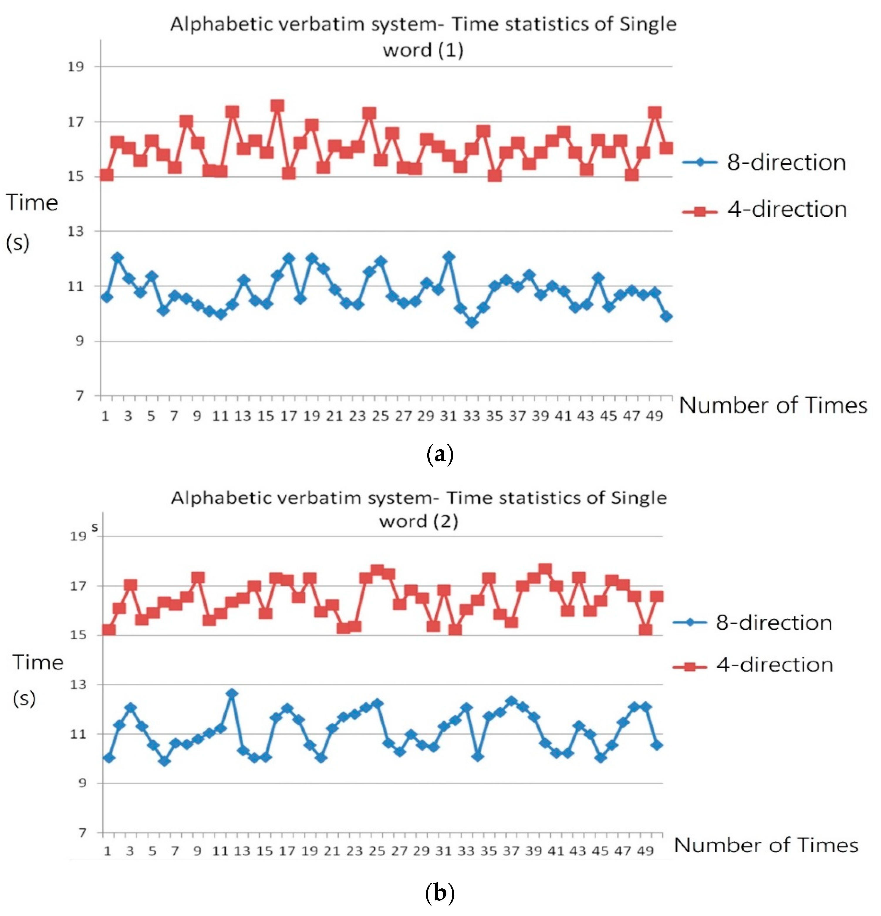
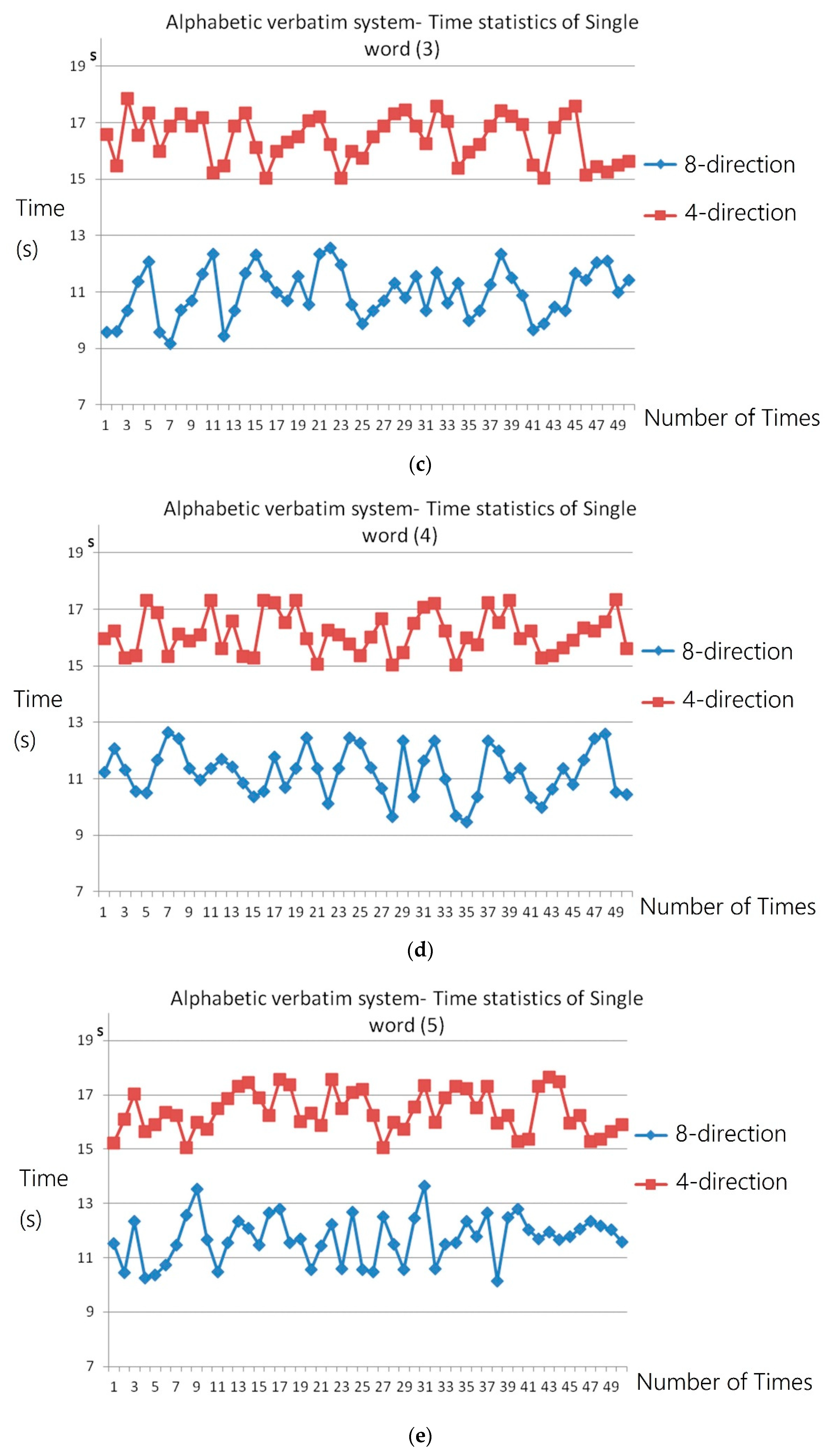
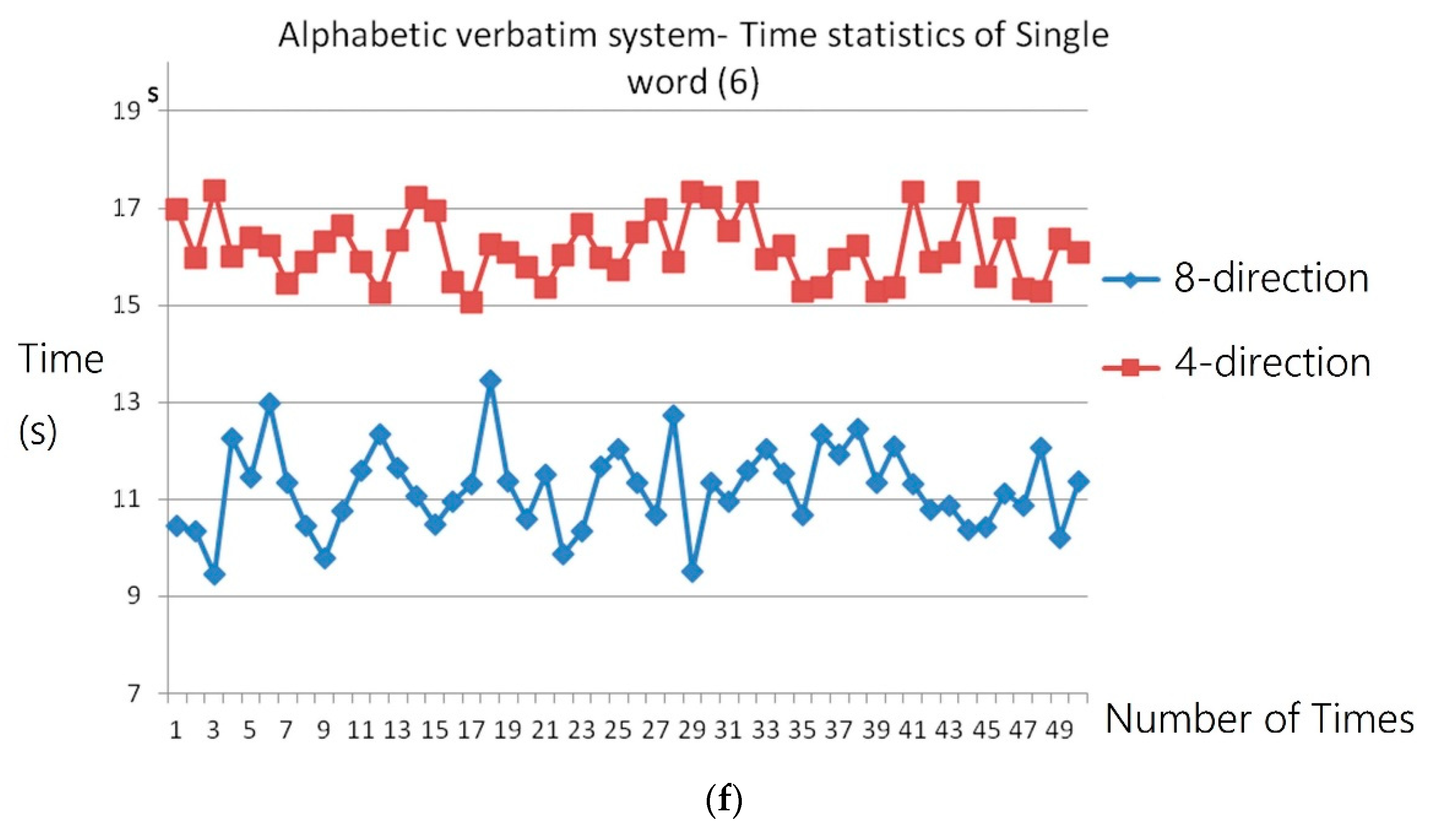
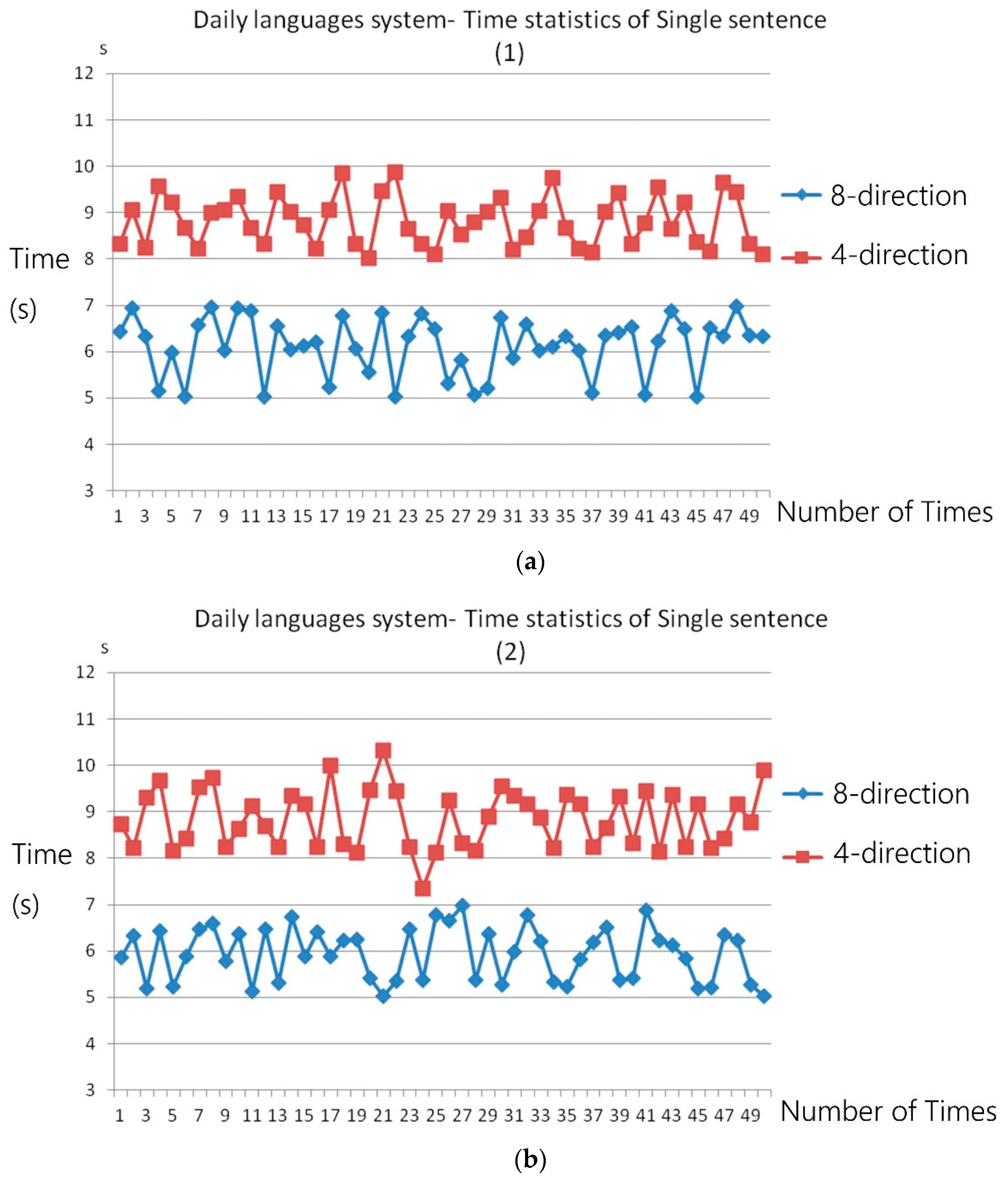
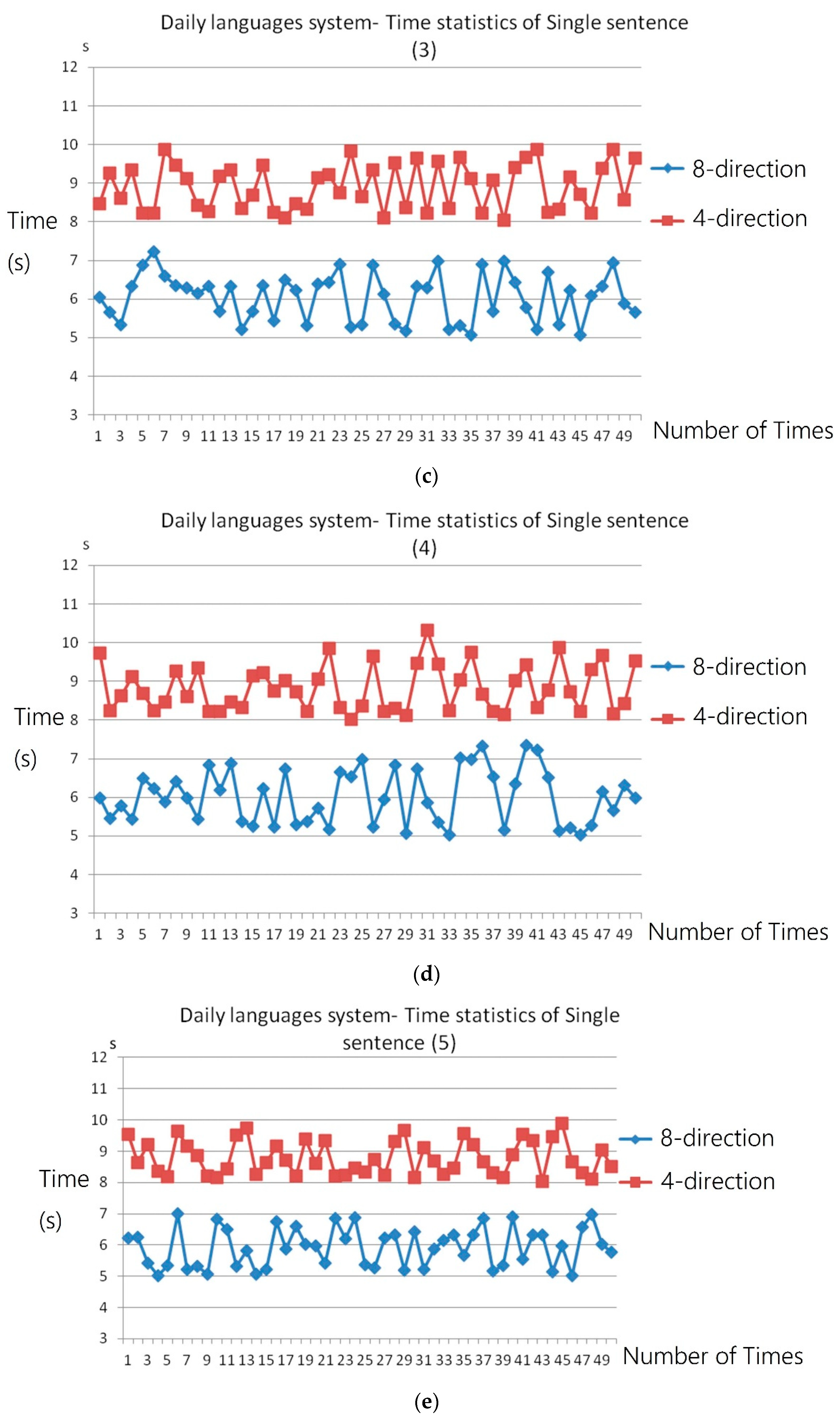
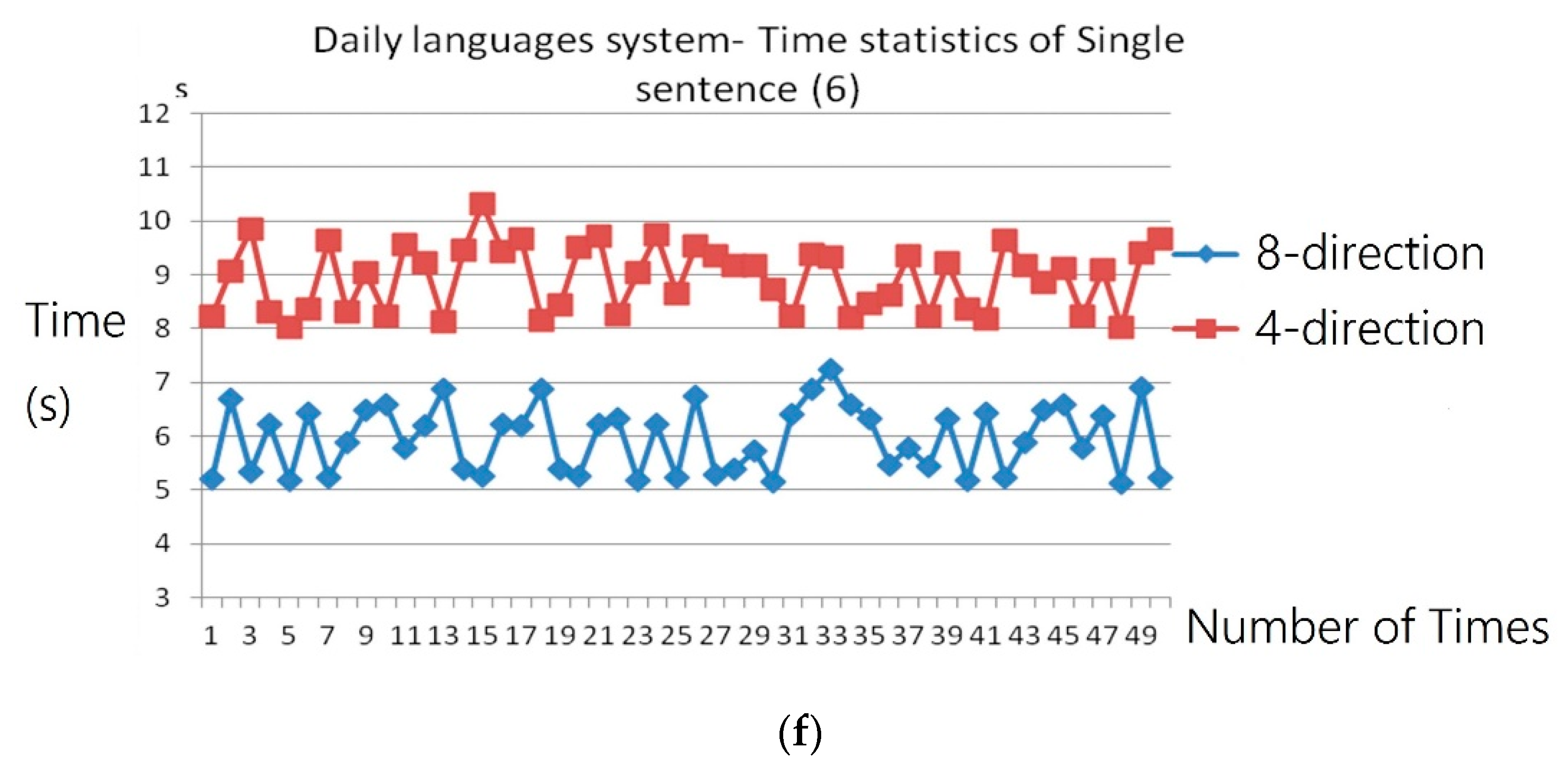
The experiment of coding time count consisted of two parts:
The two parts included the four-direction and eight-direction codes, respectively. Six users and their family members were invited to participate in the experiment. In the word-by-word sound-generating system, the words with three different syllables were taken as the testing words, and “Please help me.” was taken as the testing sentence for the pronunciation of frequently used sentences [
20,
21,
22]. The experiment results showed the average time the system required to spell a word and to finish a frequently used sentence. Recording of the time started with the user’s head turn and did not stop until the system finished the coding and generated sound.
4. Experimental Results and Discussion
According to the experiment results, the average time for the word-by-word sound-generating system to spell a word was as follows: (1) eight directions = 11.17 ± 0.85 s; (2) four directions = 16.27 ± 0.74 s. The average time for the frequently used sentence system to finish a sentence was as follows: eight directions = 6.00 ± 0.63 s; (3) four directions = 8.86 ± 0.58 s.
With the users’ experience and their suggestions, this study improved the head-controlled system. Aside from testing the system, the patients also participated in the experiment of coding time count. With head-turn images filmed by the CCD and image scanning, this study obtained the parameters of a head turn and facilitated position detection. The obtained parameters were used as coding elements in a phonetic system. As head feature colors could be captured, it was possible to locate the head without the parameters set in the procedure. This not only simplified parameter adjustment, but also enabled the camera to locate the head at any time.
In this study, different test environments and scenes were taken, and test results were used as adjustment coefficients in image processing. After the tests, the image processing and environment control methods most suitable for the system were found. The methods could lead to the correct judgment of head-turn directions. The system was used for repeated experiments, and the misjudgment rate was less than 3%, which meant that the system was highly stable.
For the disabled who cannot accurately operate the bi-system coding of four or eight directions, there was a probability of misjudgment, caused by their inability to control their bodies. In the future, it is suggested that image judgment should be upgraded to make the program more complete. Additionally, the existing four-direction coding is too difficult for Chinese grammatical coding. If it could be extended to the eight-direction judgment for coding, then the combination of the recognized data and the phonetic system would allow users to operate the system more conveniently.
The detection and coding of the system could also be applied to a rehabilitation system for the disabled. Unlike the traditional method, where the architecture is specifically designed for different movement control training, the combination of computer vision technology and movement control training enables users to train themselves with head turn games, makes rehabilitation training more attractive, and equips rehabilitation with both training and entertainment.
5. Conclusions
This study developed a system where machine vision technology was integrated with action-control for display on a numeric human–machine interface and applied it to a phonetic system for patients with general paralysis. The system used machine vision technology to detect eight directions of head motion and displayed the obtained direction data on the human–machine interface. This was then combined with a phonetic module to develop software that generated sound according to head control. Differently from traditional supporting devices for those with physical problems, the interactive head-control device featuring the combination of machine vision technology and action recognition was both practical and convenient. This device had many applications in complex and economical equipment, as confirmed by its use in environmental control. We hope our head-control device can become more useful for human–machine interfaces in the future.
Author Contributions
Conceptualization, C.-M.C., C.-S.L., W.-C.C., C.-T.C. and Y.-L.H.; methodology, C.-M.C. and C.-S.L.; software, W.-C.C.; validation, C.-S.L., W.-C.C. and Y.-L.H.; formal analysis, C.-S.L. and W.-C.C.; investigation, C.-M.C.; resources, C.-S.L.; data curation, C.-T.C.; writing—original draft preparation, C.-S.L.; writing—review and editing, C.-S.L. and C.-M.C.; visualization, C.-M.C.; supervision, C.-S.L.; project administration, C.-S.L., Y.-L.H., and C.-M.C.; funding acquisition, C.-S.L., C.-M.C., and Y.-L.H. All authors have read and agreed to the published version of the manuscript.
Funding
This research project was supported by the Ministry of Science and Technology, under Grant No. MOST 108-2628-E-035-002-MY3 and MOST 108-2221-E-035-069.
Conflicts of Interest
The authors declare no conflict of interest. The funders had no role in the design of the study; in the collection, analyses, or interpretation of data; in the writing of the manuscript, or in the decision to publish the results.
References
- Hands, G.L.; Stepp, C.E. Effect of age on human–computer interface control via neck electromyography. Interact. Comput. 2016, 28, 47–54. [Google Scholar] [CrossRef] [PubMed]
- Lamberti, L.; Camastra, F. Handy: A real-time three color glove-based gesture recognizer with learning vector quantization. Expert Syst. Appl. 2012, 39, 10489–10494. [Google Scholar] [CrossRef]
- Yang, S.W.; Lin, C.S.; Lin, S.K. Design of virtual keyboard using blink control method for the severely disabled. Comput. Methods Programs Biomed. 2013, 111, 410–418. [Google Scholar] [CrossRef] [PubMed]
- Lin, C.S.; Yang, H.J.; Lay, Y.L.; Yang, S.W. The design idea and use intention evaluation of a public installation of an eye-gaze system. Assist. Technol. 2011, 23, 187–198. [Google Scholar] [CrossRef] [PubMed]
- Liu, L.; Shao, L.; Rockett, P. Boosted key-frame selection and correlated pyramidal motion-feature representation for human action recognition. Pattern Recognit. 2013, 46, 1810–1818. [Google Scholar] [CrossRef]
- Lun, R.; Zhao, W. A survey of applications and human motion recognition with microsof kinect. Int. J. Pattern Recognit. Artif. Intell. 2015, 29, 1–48. [Google Scholar] [CrossRef]
- Lancioni, G.E.; Reilly, M.F.O.; Singh, N.N.; Oliva, D.; Scalini, L.; Vigo, C.M.; Groeneweg, J. Microswitch clusters to enhance adaptive responses and head control: A programme extension for three children with multiple disabilities. Disabil. Rehabil. 2005, 27, 637–641. [Google Scholar] [CrossRef]
- Drosou, A.; Ioannidis, D.; Moustakas, K.; Tzovaras, D. Spatiotemporal analysis of human activities for biometric authentication. Comput. Vis. Image Underst. 2012, 116, 411–421. [Google Scholar] [CrossRef]
- Lin, C.S.; Ho, C.W.; Chang, K.C.; Hung, S.S.; Shei, H.J.; Yeh, M.S. A novel device for head gesture measurement system in combination with eye-controlled human–machine interface. Opt. Lasers Eng. 2006, 44, 597–614. [Google Scholar] [CrossRef]
- Canal, G.; Escalera, S.; Angulo, C. A real-time human-robot interaction system based on gestures for assistive scenarios. Comput. Vis. Image Underst. 2016, 149, 65–77. [Google Scholar] [CrossRef]
- Lee, G.C.; Loo, C.K.; Chockalingam, L. An integrated approach for head gesture based interface. Appl. Soft Comput. 2012, 12, 1101–1114. [Google Scholar] [CrossRef]
- Terven, J.R.; Raducanu, B.; Meza-de-Luna, M.E.; Salas, J. Head-gestures mirroring detection in dyadic social interactions with computer vision-based wearable devices. Neurocomputing 2016, 175, 866–876. [Google Scholar] [CrossRef]
- Madeo, R.C.B.; Peres, S.M.; Lima, C.A.D.M. Gesture phase segmentation using support vector machines. Expert Syst. Appl. 2016, 56, 100–115. [Google Scholar] [CrossRef]
- Xiaolin, Z.; Yi, F.; Yuan, L. Intelligent wheelchair system based on sEMG and head gesture. J. China Univ. Posts Telecommun. 2015, 22, 74–80. [Google Scholar]
- Pisharady, P.K.; Saerbeck, M. Recent method sand databases in vision-based hand gesture recognition: A review. Comput. Vis. Image Underst. 2015, 141, 152–165. [Google Scholar] [CrossRef]
- Lalithamani, N. Gesture control using single camera for PC. Procedia Comput. Sci. 2016, 78, 146–152. [Google Scholar] [CrossRef]
- Halim, Z.; Abbas, G. A kinect-based sign language hand gesture recognition system for hearing- and speech-impaired: A pilot study of pakistani sign language. Assist. Technol. 2015, 27, 34–43. [Google Scholar] [CrossRef] [PubMed]
- Korkmaz, O.; Ider, S.K.; Ozgoren, M.K. Trajectory tracking control of an underactuated underwater vehicle redundant manipulator system. Asian J. Control 2016, 18, 1593–1607. [Google Scholar] [CrossRef]
- Raheja, J.; Dutta, P.; Kalita, S.; Lovendra, S. An insight into the algorithms on real-time people tracking and counting system. Int. J. Comput. Appl. 2012, 46, 1–6. [Google Scholar]
- Lee, G.H.; Yeh, F.; Hslao, Y.H. Kinect-based taiwanese sign-language recognition system. Multimed. Tools Appl. 2016, 75, 261–279. [Google Scholar] [CrossRef]
- Lin, C.S.; Lin, J.C.; Huang, Y.C.; Lai, Y.C.; Chang, H.C. The designs and applications of a scanning interface with electrical signal detection on the scalp for the severely disabled. Comput. Methods Programs Biomed. 2015, 122, 207–214. [Google Scholar] [CrossRef] [PubMed]
- Hejda, J.; Kutilek, P.; Hozman, J.; Cerny, R. Motion capture camera system for measurement of head and shoulders position. Biomed. Eng. Biomed. Tech. 2012, 57, 472–475. [Google Scholar] [CrossRef]
© 2020 by the authors. Licensee MDPI, Basel, Switzerland. This article is an open access article distributed under the terms and conditions of the Creative Commons Attribution (CC BY) license (http://creativecommons.org/licenses/by/4.0/).


