Article

Particle Swarm Optimization of a Passivity-Based Controller for Dynamic Positioning of Ships

1
Department of Mechatronics Engineering, German Jordanian University, Amman 11180, Jordan
2
IEEE Member, Piscataway, NJ 08854, USA
*
Author to whom correspondence should be addressed.
Appl. Sci. 2020, 10(20), 7314; https://doi.org/10.3390/app10207314
Submission received: 21 September 2020 / Revised: 12 October 2020 / Accepted: 14 October 2020 / Published: 19 October 2020
(This article belongs to the Special Issue Nonlinear Control: Theory and Applications)

Abstract

:
Dynamic positioning (DP) control system is an essential module used in offshore ships for accurate maneuvering and maintaining of ship’s position and heading (fixed location or pre-determined track) by means of thruster forces being generated by controllers. In this paper, an interconnection and damping assignment-passivity based control (IDA-PBC) controller is developed for DP of surface ships. The design of the IDA-PBC controller involves a dynamic extension utilizing the coordinate transformation which adds damping to some coordinates to ensure asymptotic stability and adds integral action to enhance the robustness of the system against disturbances. The particle swarm optimization (PSO) technique is one of the the population-based optimization methods that has gained the attention of the control research communities and used to solve various engineering problems. The PSO algorithm is proposed for the optimization of the IDA-PBC controller. Numerical simulations results with comparisons illustrate the effectiveness of the new PSO-tuned dynamic IDA-PBC controller.

1. Introduction

Marine vessels and ships have been widely used for offshore exploration, deep-sea mining, military operations, rigs-drilling and offshore wind farm constructions [1]. For such activities to be operated under safe and stable conditions, the vessels need to be equipped with advanced motion-control systems [2]. This has led to increasing demands for dynamic positioning (DP) systems to regulate the vessels’ plane motions in order to maintain its position and heading. The dynamic positioning systems automatically control and maintain the ship’s position and heading by means of computers, thrusters, propellers, filters, sensors and other components [3]. The capability of the ship for maneuvering and maintaining its position precisely depends on the efficiency and capacity of the components of the DP system. Precise operations require expensive hardware components (sensors, filters, etc) whose functionality and performance are degraded over time as the vessel maneuvers in the water [4]. Furthermore, the complexity and nonlinearity of the vessel dynamics and the fact that environment conditions of the sea/ocean (due to wind, waves and currents) are changeable and unpredictable have brought about new challenges on the design of DP systems [4]. The obvious alternative solution is the design of advanced and intelligent control system.
Various advanced control techniques have been thoroughly discussed in literature and successfully applied to DP systems. A comprehensive literature survey for the control methods of DP systems until 2011 have been discussed in [3]. Further review and comparison of different control techniques have been presented in the recent review in [1]. The single-input–single-output PID control is a first reported method used for DP system regulation [1,5]. A low-pass filter was combined to the PID controller to control the motion of the DP system in the 3-degrees-of-freedom (DOF) horizontal plane. PID controllers have also been used in the nonlinear PID-control approach as proposed in [6], and model free multivariable PID controller tuning method with a capability of online tuning of DP control systems [7]. The emergence of Kalman filter and optimal theories was utilized to establish more advanced control design in [8] which was adopted and further improved and extended in the works of [9,10,11,12] and the references therein.
To deal with the exact dynamics of the vessel/ship (i.e., ship’s nonlinear hydrodynamics), a number of nonlinear control methods have been proposed. State and input/output feedback linearization control methods have been discussed in [6,13,14]. Lyapunov-based design techniques including: nonlinear (passive) observer based on Lyapunov theory with wave filtering and full-scale experimental results [15], Asymmetric Barrier Lyapunov Function with Neural Networks have been deployed to control a vessel with output constraints and uncertainties [16], a combination of backstepping technique and Barrier Lyapunov Function with a passive observer to estimate some states [17]. Considering the robustness of DP system to variations in environmental and loading conditions, sliding mode control has been developed in [18,19].
Fuzzy-logic and neural network algorithm methods have the ability to reduce the complex nonlinear characteristics of the DP system controller (by means of approximation of nonlinear function) without heavy/tedious online computation requirements [20,21]. This enables online estimation with time-saving in case of dynamics variations of the DP systems due to ex. disturbances which clarifies the wide use of such methods in various control-related problems of the DP systems as in [2,5,22,23] and the references therein. Model-predictive control (MPC) is another popular control method that has recently been reported in the literature by a number of authors. Enhancement in control performance of the DP systems can be achieved deploying this method due to its systematic way in handling various (inputs, outputs and states) constraints [24], its model/performance optimization capabilities as well as its robustness against external disturbances and unmodeled dynamics [1,4]. The tracking MPC control problem of underactuated surface vessels has been proposed in [20]. In [24], both linear and nonlinear MPC approaches have been investigated for the trajectory tracking problem of autonomous vessels. Considering uncertain environmental disturbances, measurement errors and partially measured states, two robust control methods based on MPC and using a simple Luenberger observer for DP systems control problem of autonomous surface vessels have been discussed in [4].
Passivity-based control (PBC) is another class of nonlinear control methods that have received a lot of interest due to its advantages in reducing the complexity in the control design [3] exploiting intrinsic system properties. By invoking the physically motivated principles of energy dissipation and transformation, the stabilization of the dynamical system is achieved fulfilling its passivity property which is related to the stability properties of the systems [25]. The PBC problem aims at making the closed loop system passive by shaping both the energy and internal interconnection structure of the system. The most notable example of the PBC approach is the interconnection and damping assignment-passivity based control (IDA-PBC) which has already been successfully applied to various dynamical systems adopting port-Hamiltonian (PH) formalism [26]. In addition to energy and structural shaping of the PH model, damping is injected by means of feedback control to ensure asymptotic stability of the closed-loop system. Passivity theory has been used in [6] to establish a passive nonlinear observer and in [27] a passivity-based controller based on IDA-PBC method has been proposed to stabilize a DP system of ship.
Focusing on enhancement of the control performance, optimization techniques have been widely used and applied. They provide systematic procedure for designing of controllers, tuning the parameters and gains, and online estimation/calibration for unknown parameters caused by environmental changes or disturbances [21,28]. In the literature, various optimization algorithms have been developed to improve the quality of the closed-loop system such as Artificial Bee Colony (ABC) algorithm [29], Ant Colony Optimization (ACO) algorithm [30], Bacterial Foraging Optimization (BFO) algorithm [31], Multi-Verse Optimization (MVO) algorithm [32] and Gravitational Search Algorithm (GSA) [33]. Particle Swarm Optimization (PSO) is one of the effective optimization methods that has been successfully used in tuning PID controllers as in [34], for quadrotor stabilization based on integral backstepping control design [35], for tuning the parameters of fuzzy PD controller with minimization of integral square error cost function in [36], to improve the performance of an ultrasonic transducer [28]. For the control of DP systems, authors in [21] have deployed the PSO method to optimize the fuzzy function/parameters to enhance the quality and performance of the DP system of the ship.
In this paper, we propose a dynamic IDA-PBC controller that stabilizes the ship/vessel. It introduces a modified version of the IDA-PBC controller which was proposed in [27] by adopting the state-transformation to obtain a dynamical feedback controller with robustness capability due to the incorporation of the integral action controller. In addition, damping is injected in both the position and momenta states to ensure asymptotic stability. Furthermore, the design and selection of parameters/gains of nonlinear controllers are generally obtained using trial and error which relies mainly on experience, and usually requires tedious computations. Here, we make use of PSO algorithm to obtain the gains of the IDA-PBC controller which provides an effective way to select/tune these gains thus improving the control performance of DP system of the ship. Moreover, we provide full proofs for stability and matching between the open-loop and closed-loop models necessary to prove that the Hamiltonian structure and passivity properties are preserved despite the deployment of state-transformation method in the course of controller design procedures. Finally, we show that the proposed method guarantees robustness of DP system with respect to environmental disturbances induced by wind, waves and currents in seas and oceans.
The rest of the paper is organized as follows: Section 2 describes the dynamical model of the ship based on the PH formalism. In Section 3, the dynamic controller based on IDA-PBC method is proposed. Section 4 introduces the PSO algorithm and the suggested cost function used to tune the gains of the IDA-PBC controller. The proposed control scheme and tuning algorithm are simulated and compared in Section 5 to verify the performance of the newly PSO-tuned IDA-PBC controller. Finally, concluding remarks and future work are given in Section 6.

2. The Port-Hamiltonian Modeling of the Surface Ship

DP system of a vessel is a unit in a ship which automatically maintains its position (fixed location or predetermined track) and heading by means of thruster force [3]. The primary role of this unit is maintaining the vessel position within a given operational area with high accuracy essential to perform offshore operations in such areas. First we will give a brief description to the DP system followed by the model of the surface ship.

2.1. The DP System Overview

Conventional DP systems for vessels are usually designed to achieve reliable and accurate position/station keeping capabilities. It compromises the following main components being a set of dedicated modules which are a combination of propulsion and maneuvering devices and controllers [1,3]:
  • Power System. It compromises all components and units responsible to supply the DP system with its power requirements including: Prime movers, Generators, Switchboards, Electrical distribution system (cabling and piping), transformers. It may also include more advanced subsystems for energy storage and power management purposes.
  • Thruster system. The vessel’s horizontal motion is influenced and controlled by means of thrusters and propellers which are also the sole source of position/heading keeping. They supply the DP system with thrust force and direction and it includes thrusters with electronic drive units, propellers and rudders, cabling and piping and other associated auxiliary subsystems.
  • Control System. it compromises all hardware and software components including processors and computers, joystick control unit, Sensors and instrumentation and signal processing units, Position and heading reference systems (navigation, acoustic, microwaves and laser systems), operator and display panels.

2.2. The Mathematical Model

The motion of the marine vessel whether in maneuvering or sea-keeping state is described in 6-DOF model as shown in Figure 1 [24]. The first 3-DOF is to define translations and the other 3-DOF to define the orientation accounting for the 6 typical motion components of the marine vessels; longitudinal motion (surge), transverse (sideways) motion (sway), rotation around the vertical axis (yaw), rotation about the longitudinal axis (roll), rotation about the transverse axis (pitch), and vertical motion (heave). Typically, the position and orientation of a ship are expressed relative to two coordinate frames: the earth coordinate frame (inertial fixed frame) with origin O and (X,Y,Z) coordinates, and the body coordinate frame, which is fixed to the ship and moves along with it, with b origin and ( x , y , z ) coordinates.
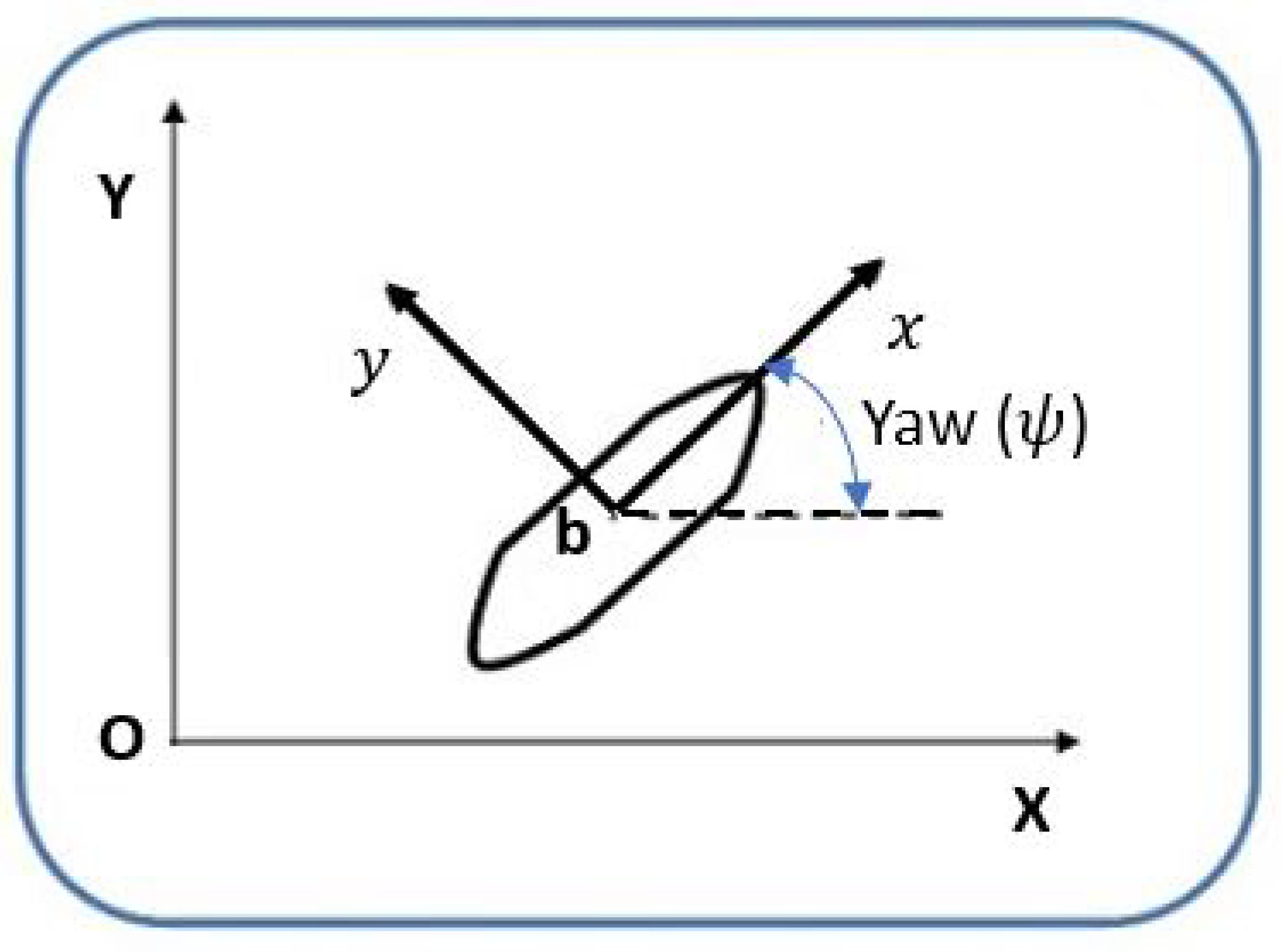
In most DP system control applications, which are featured by low-frequency and low-speed motion, rolling and pitching actions induce negligible motions and thus roll, pitch and heave motions are ignored and the control problem is reduced to a 3-DOF vessel model having a coupled surge–sway–yaw components [24,37]. An illustration of the ship model with a motion described in a horizontal plane is shown in Figure 2, with the 3-DOF (surge, sway, yaw) described in the two-coordinate frames.
The nonlinear mathematical model for vessel dynamics in horizontal plane can be expressed as [38,39]:
η ˙ v ˙ = 0 3 × 3 T ( ψ ) 0 3 × 3 M 1 D η v + 0 3 × 3 M 1 τ + 0 3 × 3 M 1 T ( ψ ) b ,
where η = [ X , Y , ψ ] is the configuration variables vector gives the position and heading angle (orientation) in the earth coordinate frame, the vector v = [ u , v , r ] represents the velocity vector expressed in the vessel’s body coordinate frame. τ R 3 is the control vector of the forces and moments produced by the ship’s propulsion system and b R 3 is the disturbances vector. The transformation matrix T represents the rotation matrix that gives the relative orientation of the inertial and body frames, the damping matrix D and the mass matrix M are all given by:
T = cos ( ψ ) sin ( ψ ) 0 sin ( ψ ) cos ( ψ ) 0 0 0 1 , D = d 11 0 0 0 d 22 d 23 0 d 23 d 33 M = M = m 11 0 0 0 m 22 m 23 0 m 23 m 33 ,
where 0 3 × 3 is the 3 × 3 zero matrix. The PH formalism for general nonlinear systems is given by [25]:
x ˙ = ( J ( x ) ( x ) ) H + G ( x ) τ y = G ( x ) H ,
where J ( x ) = J ( x ) is the interconnection matrix, ( x ) = ( x ) 0 is the damping matrix, H is the Hamiltonian (total energy ) of the system, G ( x ) is the input matrix and H is the gradient vector of the Hamiltonian. The ship model (1) can be described by pH form as [27]:
x ˙ = 0 3 × 3 T ( q 3 ) T ( q 3 ) 0 3 × 3 0 3 × 3 0 3 × 3 0 3 × 3 D q H p H + 0 3 × 3 I 3 τ + 0 3 × 3 T ( q 3 ) b
where x = [ X , Y , ψ , p 1 , p 2 , p 3 ] T = [ q 1 , q 2 , q 3 , p 1 , p 2 , p 3 ] is the state vector of the system, with the configuration states vector q = [ q 1 , q 2 , q 3 ] and the momenta vector p = [ p 1 , p 2 , p 3 ] = M v . I 3 is the 3 × 3 identity matrix. The Hamiltonian of the system is given by by its kinetic energy function
H = 1 2 p M 1 p .

3. The IDA-PBC Controller Design

In this section, we design a control law for DP system of the ship using the classical IDA-PBC and by incorporating a state-transformation which enables adding an integral action and damping controllers to achieve asymptotic stabilization. This method is resulted in a dynamic control law while preserving the PH structure. In the IDA-PBC method, the control law can be found by matching the open loop system (3) with the desired closed-loop model:
x ˙ = [ J d ( x ) d ( x ) ] H d y = G ( x ) H d ,
where J d ( x ) is the desired interconnection matrix, d ( x ) is the desired damping matrix and H d is the desired Hamiltonian. The following proposition establishes procedures for the design of the controller:
Proposition 1.
Consider the PCH system (4). Define the coordinates transformation
x = f ( q , p ) z = f ( z 1 , z 2 , z 3 ) ,
with
z 1 = q , z 2 = p M K I z 3 + M T 1 ( q 3 ) K q z 1 Ψ , z 3 = T ( q 3 ) z 1 H d .
Define the desired Hamiltonian function
H d = Ψ ( z 1 ) + 1 2 z 2 M 1 z 2 + 1 2 z 3 K I z 3 ,
where Ψ ( z 1 ) is desired potential energy function which has a minimum at z 1 = 0 . Then the closed-loop PCH system is obtained as
z ˙ 1 z ˙ 2 z ˙ 3 = K q T ( q 3 ) T ( q 3 ) T ( q 3 ) K p 0 3 × 3 T ( q 3 ) 0 3 × 3 0 3 × 3 z 1 H d z 2 H d z 3 H d ,
and the dynamic control law
u = T ( q 3 ) M K I T ( q 3 ) K p T 1 ( q 3 ) K q + M T 1 ( q 3 ) d d t [ T ( q 3 ) ] T 1 ( q 3 ) K z 1 z 1 Ψ ( K p D ) M 1 p + K p K I z 3 M T 1 ( q 3 ) K q d d t [ z 1 Ψ ] T ( q 3 ) b ,
with the update law
z ˙ 3 = T ( q 3 ) z 1 H d ,
(asymptotically) stabilized the ship at the desired equilibrium point ( z 1 , z 2 , z 3 ) = ( 0 , 0 , 0 ) .
Remark 1.
In the closed-loop model (9), K q = d i a g { k q 1 , k q 2 , k q 3 } > 0 and K p = d i a g { r 1 , r 2 , r 3 } > 0 are the damping matrices injected in the configuration z 1 and momenta z 2 coordinates, respectively, which ensure asymptotic stability. K I = d i a g { k i 1 , k i 2 , k i 3 } > 0 is a constant integral matrix which improves the robustness of the closed-loop system against external disturbances and steady-state errors.
Proof of Proposition 1.
Considering the function (8) as a candidate Lyapunov function, the time derivative of this function along the trajectories of (9) is given by:
H ˙ d = z 1 H d z ˙ 1 + z 2 H d z ˙ 2 + z 3 H d z ˙ 3 = z 1 H d ( K q z 1 H d + T ( q 3 ) z 2 H d + T ( q 3 ) z 3 H d ) + z 2 H d ( T ( q 3 ) z 1 H d K p z 2 H d ) + z 3 H d ( T ( q 3 ) z 1 H d ) = z 1 H d K q z 1 H d z 2 H d K p z 2 H d .
 □
Using a quadratic energy function
Ψ ( z 1 ) = 1 2 z 1 C z 1 ,
where C > 0 is the gain matrix such that the quadratic function has its minimum at z 1 = 0 and substituting (13) into (12) we obtain
H ˙ d = z 1 C K q z 1 z 2 M 1 K p M 1 z 2 .
Using the norm-notation defined as y A : = y A y [25], (14) can be expressed as the following inequality
= z 1 C K q 2 M 1 z 2 K p 2 0 ,
which ensures stability of the system at its desired equilibrium. Asymptotic stability at the desired equilibrium point can be satisfied using the following detectability condition (the detectability condition has been used in [40] although not exactly in the same context):
Condition 1.
The output
y d = z 1 M 1 z 2
is a detectable output of the dynamics (9).
The realization of the closed-loop dynamics (9) via the coordinate-transformation (7) can be verified by matching the states of the open-loop system (4) with their corresponding states in the closed-loop system (9). That is, for the position state
q ˙ in ( 4 ) z ˙ 1 in ( 9 ) T ( q 3 ) p H = K z 1 z 1 Ψ + T ( q 3 ) z 2 H d + T ( q 3 ) z 3 H d .
Substituting p H from (5) and z 2 H d , z 3 H d from (8), we obtain
T ( q 3 ) M 1 p = K z 1 z 1 Ψ + T ( q 3 ) M 1 z 2 + T ( q 3 ) K I z 3
Finally, substituting z 2 from (7), the left-hand and right-hand sides are equivalent. Similarly, the equivalency between p and z 2 states that established the control law (10) can be found by differentiating the transformation (7) with respect to time and using d d t ( A B ) = d A d t B + A d B d t and d d t ( T 1 ) = T 1 d d t ( T ) T 1 :
z ˙ 2 = p ˙ M K I z ˙ 3 + M T 1 ( q 3 ) K q d d t [ z 1 Ψ ] + M T 1 ( q 3 ) d d t [ T ( q 3 ) ] T 1 ( q 3 ) K q z 1 Ψ .
Substituting ( z ˙ 2 , z ˙ 3 , p ˙ ) from the dynamics (4), (9) yields:
T z 1 Ψ K p M 1 z 2 T z 1 H D p H + τ + T b + M K I T z 1 Ψ M T 1 d d t [ T ] T 1 K z 1 z 1 Ψ + M J 1 K z 1 d d t [ z 1 Ψ ]
Substituting z 2 from (7) and rearranging, we obtain the dynamic controller (10).
Remark 2.
Here, we have shown that the proposed method stabilized the ship at its desired equilibrium position and orientation using the states (coordinates)-transformation without destroying the PH structure nor the passivity properties.

4. The PSO Method for DP of Ship

Similar to most nonlinear control approaches, the gains and parameters of the IDA-PBC control law (10) are generally obtained using trial and error which relies mainly on experience, and usually results in tedious computations. Here, we utilize the PSO algorithm to obtain the optimal gains of this controller which provides an effective way to tune these gains thus improving the control performance of DP system of the ship.

4.1. An Overview of PSO Method

Since its introduction in [41], particle swarm optimization (PSO) algorithm has received wide attention and has been widely used for various optimization applications. Inspired by the social and intelligent collective behavior of animals (such as insects, herds, birds and fishes) and the learning experiences they develop conforming cooperatively some ways in searching for food [42,43]. The PSO design is a population-based stochastic optimization algorithm which has the advantages of simple implementation and simple integration with other optimization methods as well as its rapid convergence capability [43]. In this algorithm, a group of particles called population moves in the search-space looking for the optimal value of a performance index (fitness function). The position and the velocity of each particle is updated according to mathematical equations which are:
x i j n + 1 = x i j n + v i j n + 1
v i j n + 1 = w v i j n + r 1 c 1 ( p i j n x i j n ) + r 2 c 2 ( g j n x i j n ) ,
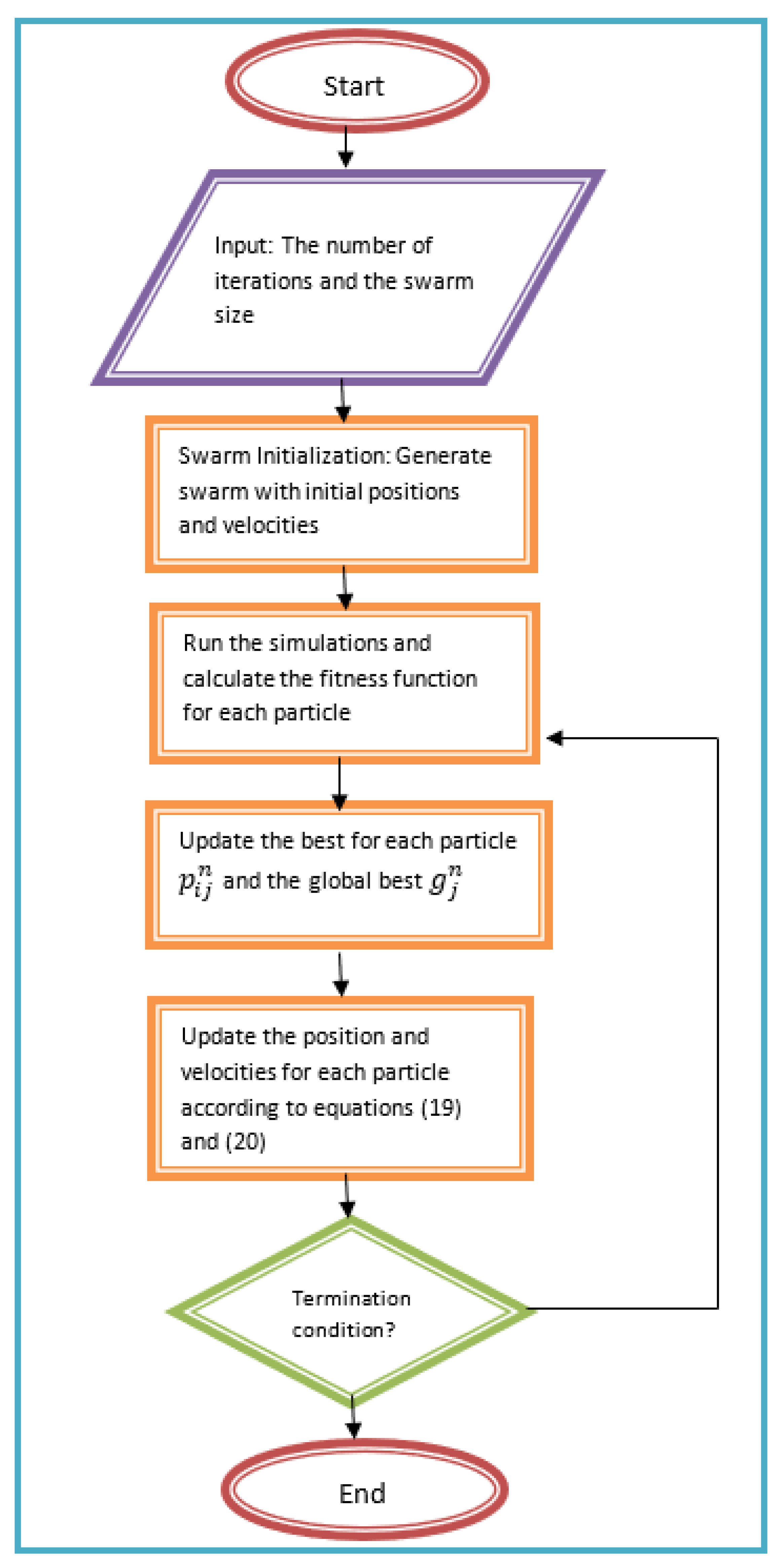
where x i j n is the position of the particle i at the current iteration in the j dimension, x i j n + 1 is the position of the particle at the next iteration, v i j n is the velocity of the particle i at the current iteration, v i j n + 1 is the velocity of the next iteration, w is the inertia weight, c 1 is the self-weight acceleration coefficient, c 2 is the social-weight acceleration coefficient, r 1 and r 2 are uniformly distributed numbers, p i j n is the best previous position (with minimum fitness value) of the particle i in the j dimension until the current iteration n and g j n is the position of the best particle in the dimension j at the current iteration. The flow-chart of the PSO algorithm is illustrated in Figure 3.

4.2. Application of PSO Algorithm for DP of Ship

In this work, the PSO was used to tune the modified passivity-based controller for improving the performance of a dynamic positioning system in a surface ship. The design space is the controller gains which are the diagonal elements in ex. K q matrix:
X D e s i g n = ( k q 1 , k q 2 , k q 3 ) .
The objective that used in this optimization is the performance index integral square error (ISE) which can be defined for the three outputs (x-position, y-position and yaw angle ( ψ )):
I S E = t 0 t f e x ( t ) 2 + e y ( t ) 2 + e ψ ( t ) 2 ,
e x ( t ) is the error in the x-position, e y ( t ) is the error in the y-position and e ψ ( t ) is the error in the yaw angle. We used this method (the summation of the three errors) in preparing the performance index as in [36].

4.3. Convergence to the Optimal Solution Using PSO Method

In terms of convergence of the function to the optimal solution, optimization methods can be split into two groups; local and global optimization methods. The local optimization could ensure the function/algorithm convergence to the local optimal solution while the global methods could guarantee a convergence to a global solution among multiple local optima. Moreover and based on the local or global convergence condition, optimization techniques can be decomposed into two main methods: the metaheuristic and deterministic methods following their tendency to converge towards a local or global optimum, respectively [44].
Most metaheuristic methods are naturally or biologically motivated mimicking the behavioral characteristics and/or interactions of living agents such as worms, fish, birds, bees [45]. Metaheuristic methods are gaining popularity in several application domains including in control system, neural network training and function optimization due to their ease of implementation, rapid convergence capability without requiring high mathematical preparation and computational complexity [42,46]. The most popular metaheuristic methods, which have been used to solve a wide range of real-life optimization problems, are differential evolution, artificial bee colony, particle swarm optimization, genetic algorithm, simulated annealing, gravitational search algorithm and firefly algorithm [44,46]. On the other hand, deterministic methods follow a definite trajectory to the closest minimum from random initial solution(s), which ensure more accurate results. However, these methods require sophisticated mathematics and extensive computation. They also need a lot of memory for sampling and lengthy simulations [46,47]. Charactarized by the fact that the selected objective function must satisfy the Lipschitz condition, a number of approaches have been proposed in the literature; the DIRECT method and its locally-biased version DIRECT-L, and the approach based on adaptive diagonal curves [46], and the geometric global optimization methods [44].
To guarantee that our proposed PSO approach converges to the optimal value, we used the PSO algorithm implemented in the Global Optimization Toolbox in Matlab. This toolbox examines several basins of attraction to find the global optima [48]. This Global Optimization Toolbox “provides functions that search for global solutions to problems that contain multiple maxima or minima. This gives some confidence that particleswarm reports a local minimum and that the final obtained value is the global solution [49]”. Furthermore, and based on the comprehensive discussion and analysis in [44], PSO methods manifest a better performance as well as being less sensitive to the accuracy increment with respect to the other tested metaheuristics. In addition, trial points generated by PSO were distributed in a smarter manner with respect to the other metaheuristics and even better than some global methods [44]. Motivated by these points and due to the fact that PSO method solves the optimization problem in a computationally efficient manner, we have adopted this method among other optimization methods. It’s effectiveness will be verified in the next section.

5. Numerical Simulations

Three sets of numerical simulations based on the 3-DOF planar model of the ship (vessel) were carried out to demonstrate the effectiveness of the proposed control design. The first set of simulations demonstrates the improved design, the second shows the role of PSO tuning method, and the third shows the robustness of the closed-loop against external disturbances. All the simulations have been implemented in the Matlab/Simulink environment.

5.1. A Comparison between the Modified and the Original Controllers

To show the effectiveness of the proposed controller, we have compared it with the original proposed in [27]. The values of the model parameters M and D are [27]:
M = 1.1274 0 0 0 1.8902 0.0744 0 0.0744 0.1278 , D = 0.0358 0 0 0 0.1183 0.0124 0 0.0124 0.0308 ,
and the controller gains have been selected as:
K p = 1.5 0 0 0 1 0 0 0 0.3 , K I = 0.05 0 0 0 0.03 0 0 0 0.06 K z 1 = 1.0 0 0 0 1.0 0 0 0 1.0 , C = 0.01 0 0 0 0.01 0 0 0 0.08
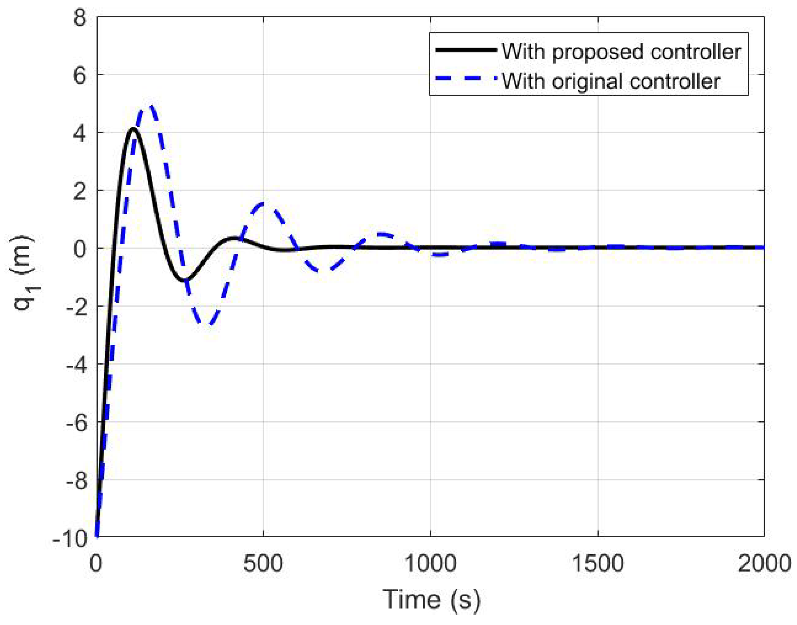
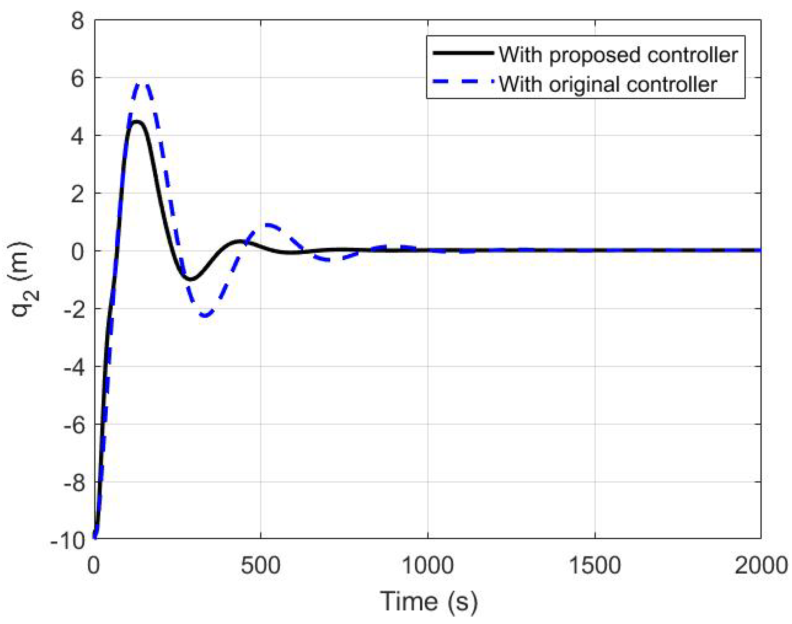
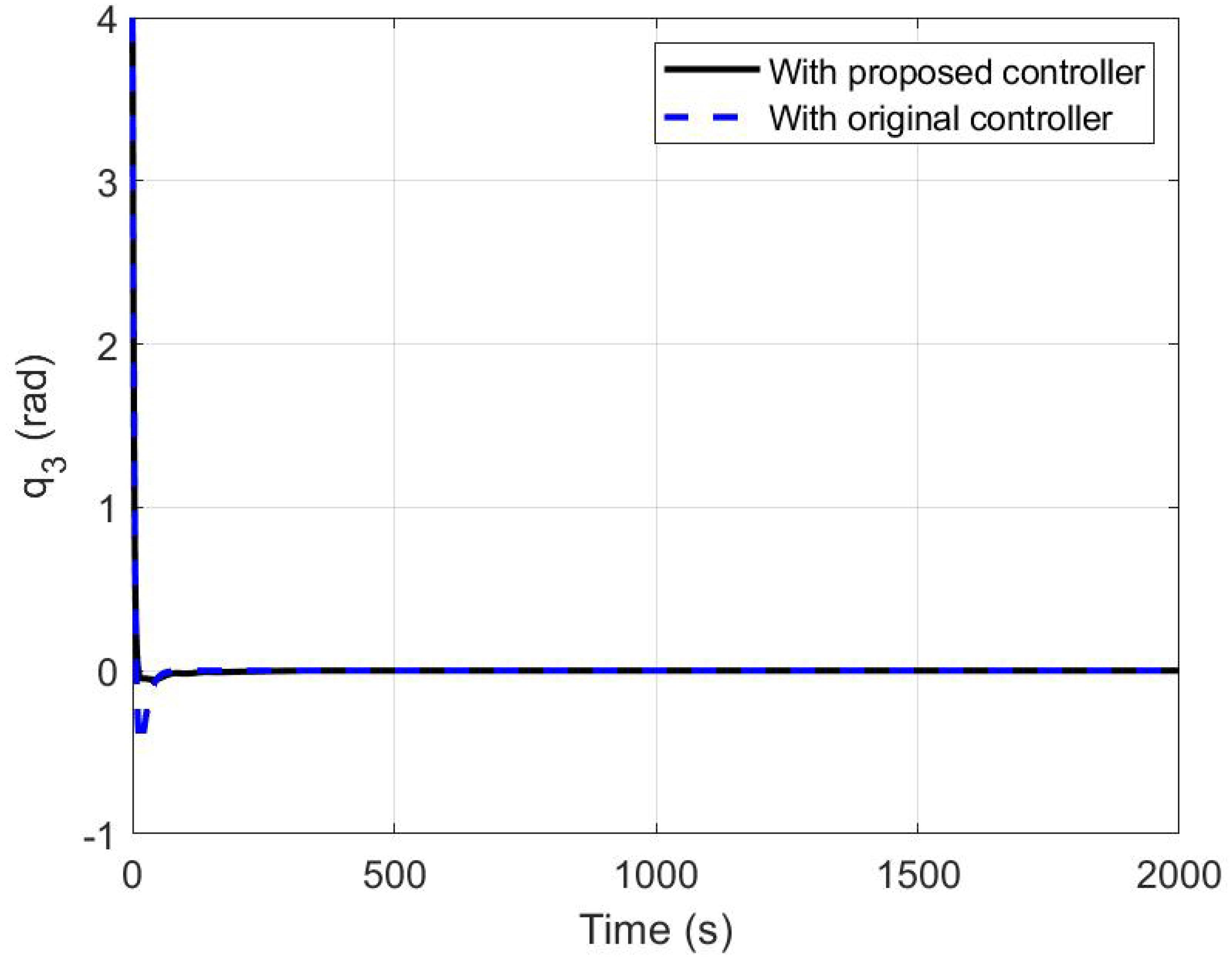
The initial state (initial position and orientation of the ship) has been chosen as 10 m for both positions ( q 1 , q 2 ) and 4 rad for yaw angle ( q 3 ). The aim is to stabilize the ship at its desired equilibrium (0,0,0). Figure 4 and Figure 5 show the time histories of the position states q 1 (position in x coordinate) and q 2 (position in y coordinate,) and Figure 6 shows the time history of the orientation (heading) q 3 (yaw angle). The figures show simulations using both the original and proposed controllers. The performance (time response characteristics) for both controllers are shown in Table 1. The improvement on the performance of the closed-loop system using the proposed controller over the classical one has been demonstrated evident by faster response, less overshoot in the x and y directions as well as an improved undershoot in the yaw angle.

5.2. The PSO Tuning of the Proposed Controller

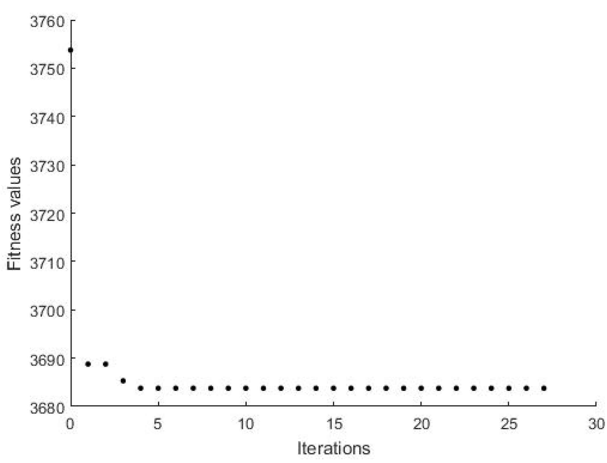
Here, we show the procedures to tune the controller gains as discussed in Section 4. We use the same model parameters as in the previous subsection. The algorithm parameters are shown in Table 2. The iterations versus the fitness values for ISE are shown in Figure 7. The termination happened before the maximum iteration because of the steady value of the fitness functions. The optimal values resulted from the tuning iterations are obtained as
K = 10 10 4.125 .
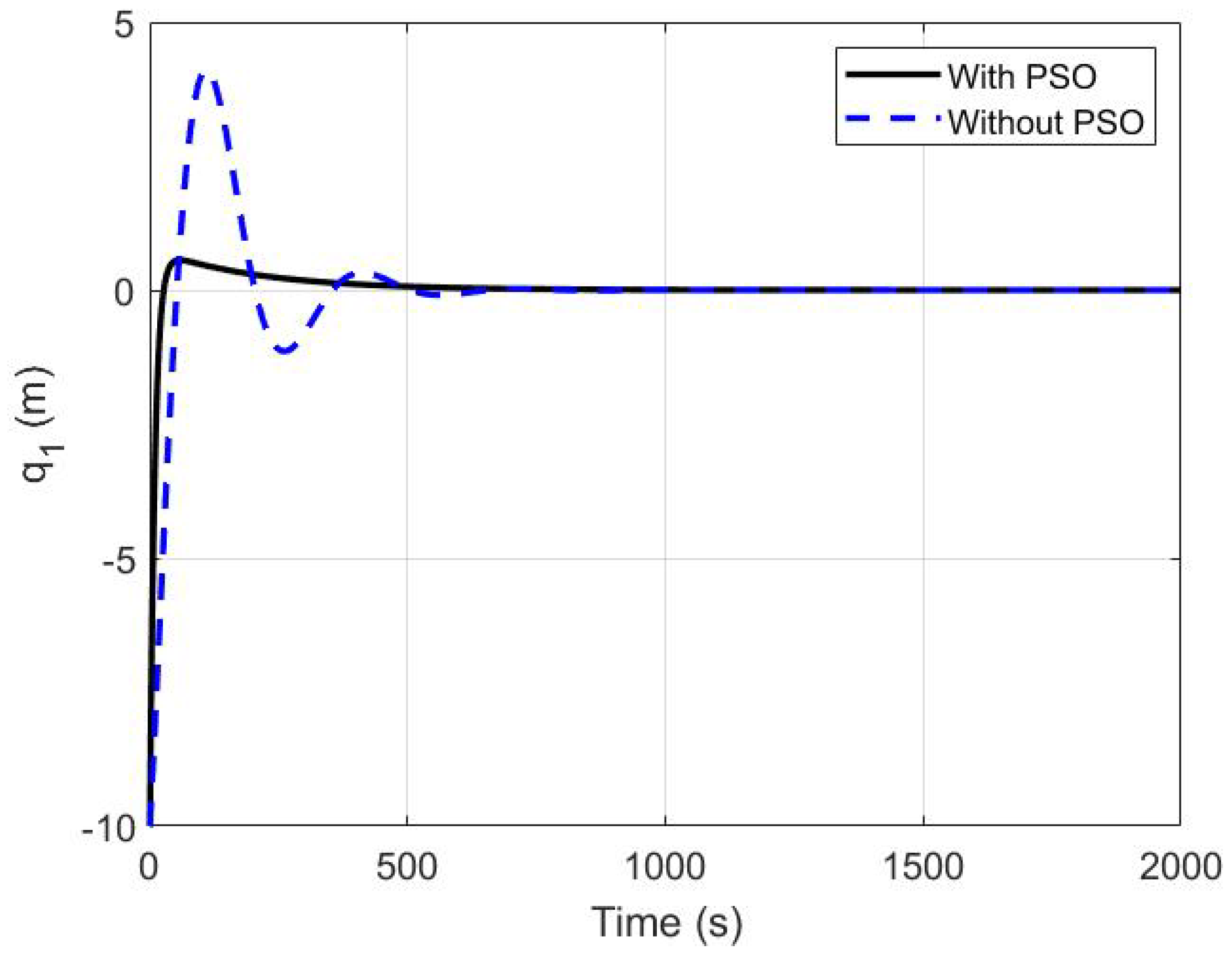
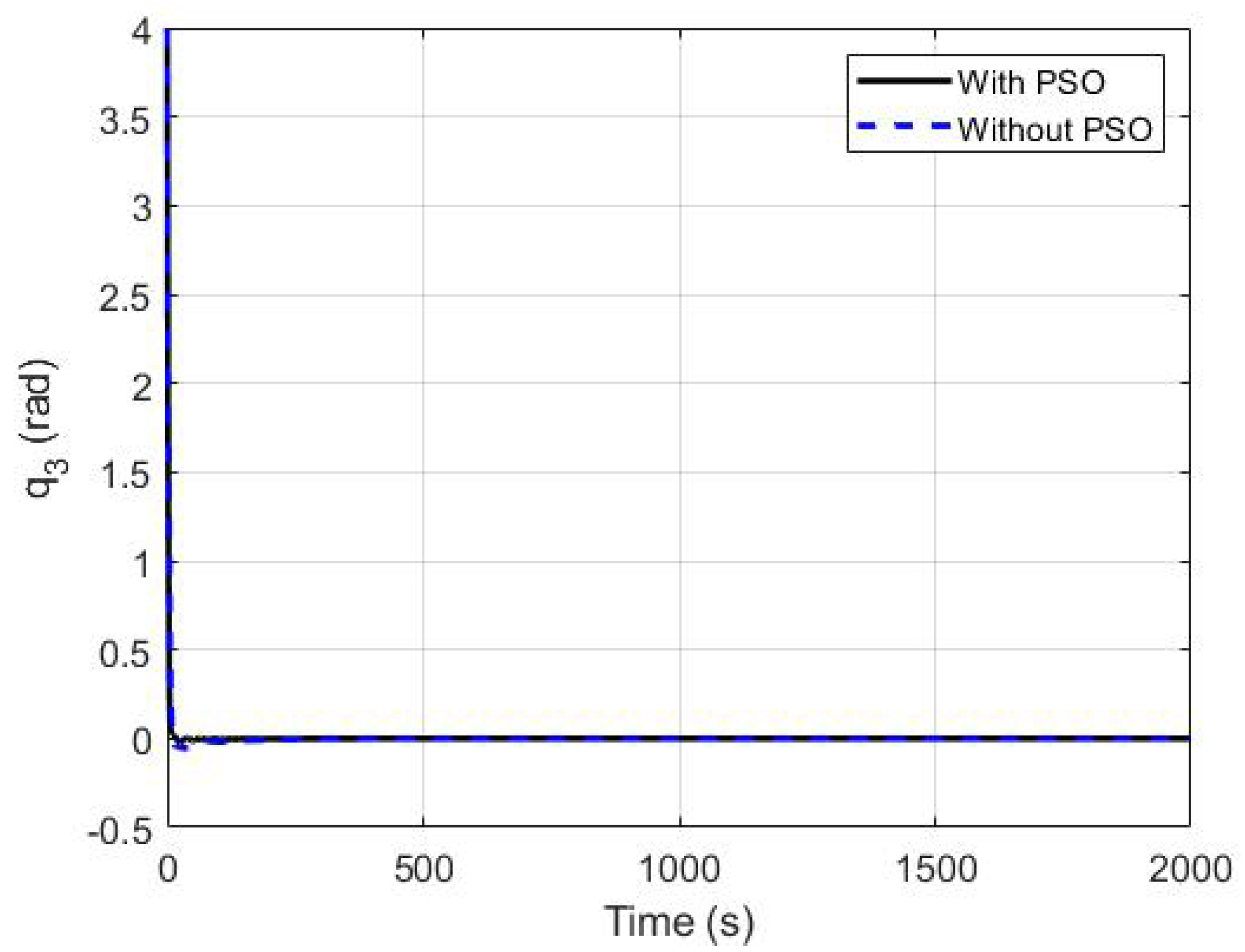
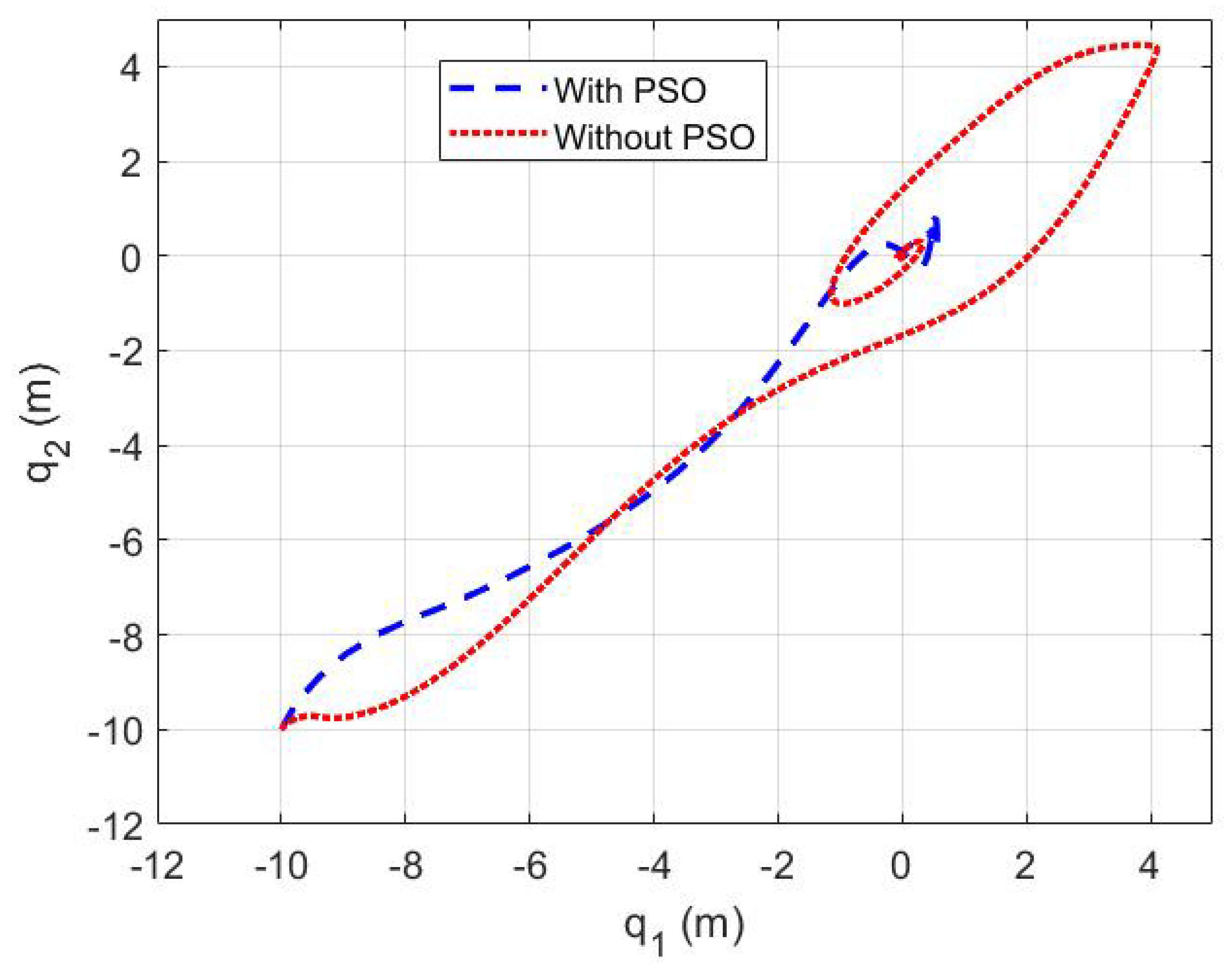
Figure 8, Figure 9 and Figure 10 show the time histories of the ship’s position and orientation using both our original proposed controller and the tuned one with PSO algorithm. It is clear from the plots that the states converge to the desired position and heading angle. The time response characteristics are shown in Table 3. We can see that PSO method improved the response of the system achieving a faster settling while reducing the overshoot (undershoot) as well as avoiding a long and time-consuming trial and error procedure to find the optimal gains. The improvement can be also shown from the trajectories for the two cases (with and without using the PSO method) in Figure 11 which clearly shows better trajectory profile and more convenient path in the case of PSO-tuned controller.

5.3. The Robustness of the Proposed Controller

A vessel operating in the sea or ocean is subjected to different disturbances due to different sea and ocean states. Such environmental disturbances due to wind, waves, and currents play an important role in the stabilization and performance of the DP system of the vessel which may cause the vessel to drift from the desired position and heading and/or oscillate [50,51]. Therefore, the disturbance rejection becomes a crucial issue in the design of DP controller.
Environmental changes cause changes to the disturbance characteristics (such as the current and wind speed, waves elevation and frequencies) of the controlled system. Such disturbances induced by wind, waves, and currents can be separated into components at lower frequencies (LF) due to the second-order waves also called slow wave drift forces [39], and components at wave–frequency (WF) disturbances due to the first-order waves. LF and WF comprises the main disturbances affecting the ship motion with LF responsible for drifting and WF for oscillation of the vessel [50]. The WF disturbances are typically tackled by wave-filtering techniques in advance [52], and DP systems can then deal with the LF disturbances which can be represented with a series of sinusoidal components with different frequencies, amplitudes and phases [51]. Different disturbances due to different sea states were described in the Code of sea state in Table 4 which are characterized by wave spectra [39].
Mathematically, the vector ( b R 3 ) in Equation (1) denotes the disturbance vector consisting of equivalent LF disturbance forces b 1 ( t ) in surge, disturbance force b 2 ( t ) in sway and disturbance moment b 3 ( t ) in yaw.
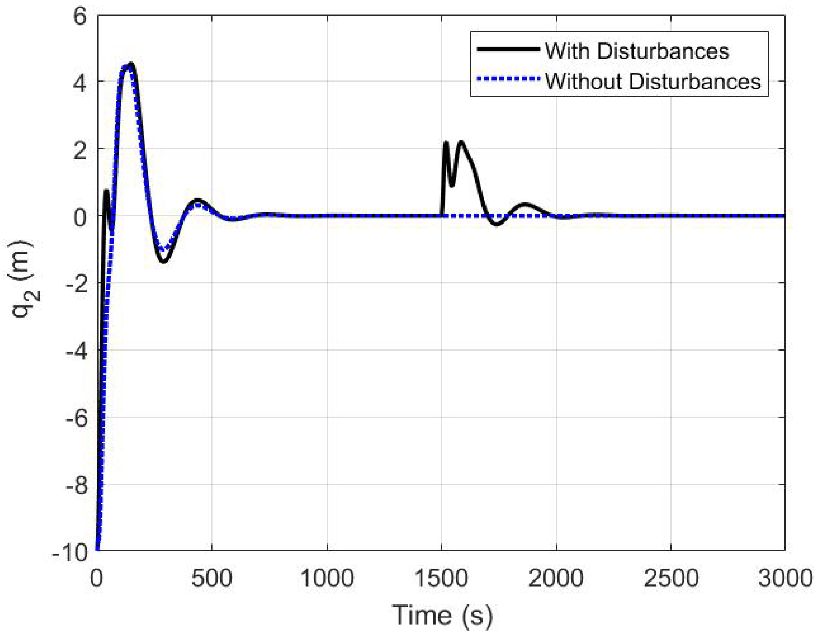
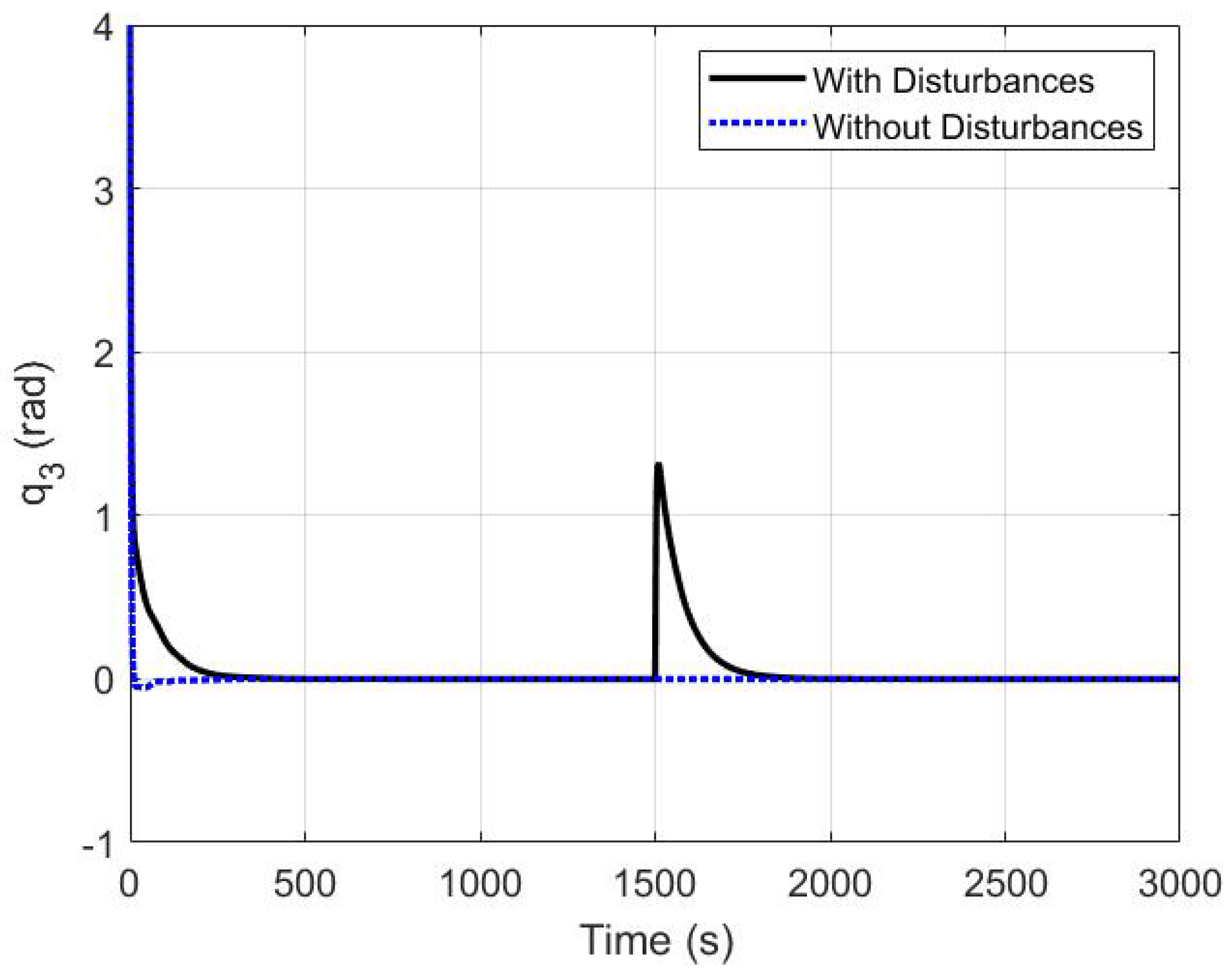
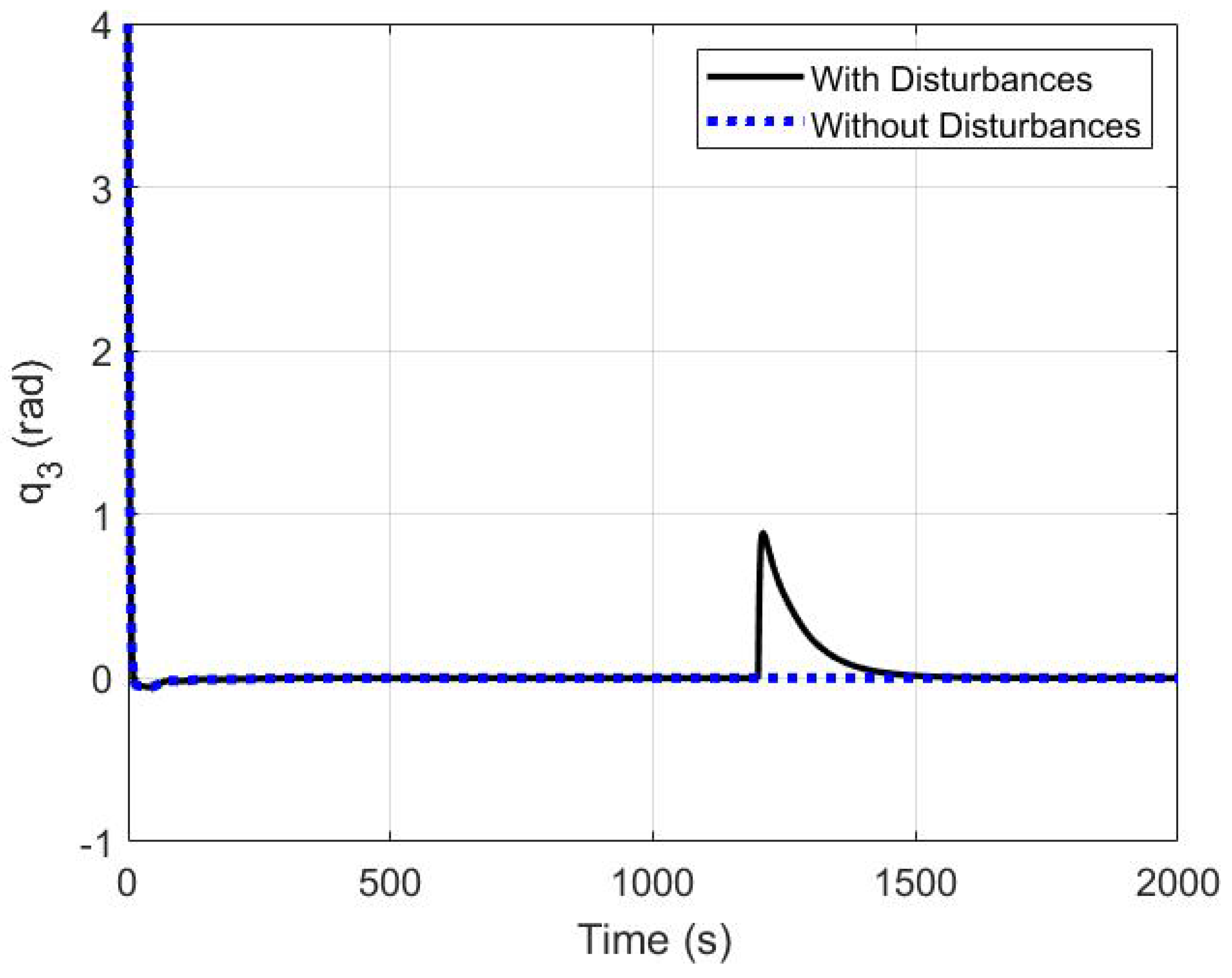
Here, we show the capability of the proposed dynamic control law, by incorporating the integral action term, in rejecting externally induced disturbance, hence, achieving robust bounded control performance. We demonstrated our proposed design with two sets of simulations for two different scenarios; in the first scenario a vessel has been disturbed (at T = 0 s) by constant wind and current speeds and constant wave height, then being suddenly disturbed by stronger wind and current, and higher wave at (T = 1500 s). Figure 12, Figure 13 and Figure 14 show the response of the closed-loop system in presence of disturbances which have been induced to the system at time (T = 1500 s). As shown, the proposed controller has rejected the environmental disturbances and forced the ship to return back to its desired position (equilibrium) demonstrating its effectiveness and robustness in spite of disturbances.
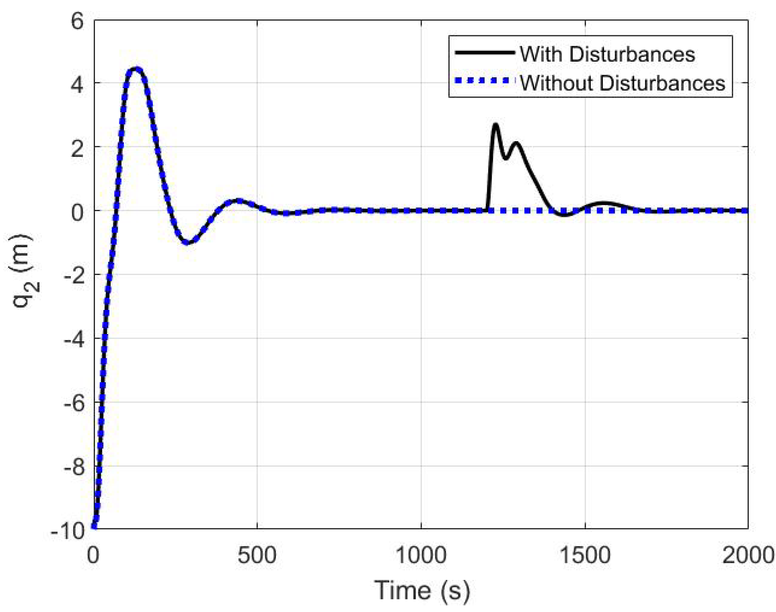
In the second scenario, the vessel started in the slight sea state (code no. 3 in Table 4) and then environmental changes associated with moderate sea state (code no. 4) disturbed the vessel at time (T = 1200 s). The values of wave height, peak frequency and direction, and wind/current speeds angles and directions have been taken from [51] adopting the Jonswap spectrum which has been discussed in [39]. As depicted in Figure 15, Figure 16 and Figure 17, the ship position and heading in the x , y , ψ coordinates have been affected by the environmental disturbances (sea state changes) as expected, however, the controller quickly suppressed the disturbances and the ship returned back to its desired position and orientation.

6. Conclusions and Future Work

In this paper, a dynamic IDA-PBC controller has been proposed for the dynamic positioning of surface ships. The tuning of the gains of the IDA-PBC controller based on the PSO method has also been discussed. Moreover, we employed the dynamic extension on the PCH model to improve the IDA-PBC controller for DP of ships. Asymptotic stabilization of the system is achieved by injecting damping on the position and momenta states while robustness of the closed-loop system against disturbances is ensured by the integral action control. Finally, the effectiveness of the proposed controller using the PSO tuning method has been verified through simulations which revealed improved convergence speed and less overshoots. Future work includes using multi-objective optimization and further investigation to the adaptive and robust control problems associated with the uncertainties and time-varying disturbances.

Author Contributions

Conceptualization, M.R., H.S.D. and H.E. Methodology, M.R., H.S.D. and H.E.; Software, M.R., H.S.D. and H.E.; Validation, M.R., H.S.D. and H.E.; Formal Analysis, M.R., H.S.D. and H.E.; Investigation, M.R., H.S.D. and H.E.; Resources, M.R.; Data Curation, M.R., H.S.D. and H.E.; Writing–Original Draft Preparation, M.R., H.S.D. and H.E.; Writing, Review and Editing, M.R., H.S.D. and H.E.; Supervision, M.R.; Project Administration, M.R. All authors have read and agreed to the published version of the manuscript.

Funding

This research received no external funding.

Conflicts of Interest

The authors declare no conflict of interest.

References

  1. Mehrzadi, M.; Terriche, Y.; Su, C.-L.; Othman, M.B.; Vasquez, J.C.; Guerrero, J.M. Review of Dynamic Positioning Control in Maritime Microgrid Systems. Energies 2020, 13, 3188. [Google Scholar] [CrossRef]
  2. Zhu, X.; Sun, L.; Li, S. Dynamic analysis of vessel/riser/equipment system for deep-sea mining with RBF neural network approximations. Mar. Georesources Geotechnol. 2020, 38, 174–192. [Google Scholar] [CrossRef]
  3. Sørensen, A.J. A survey of dynamic positioning control systems. Annu. Rev. Control 2011, 35, 123–136. [Google Scholar] [CrossRef]
  4. Zheng, H.; Wu, J.; Wu, W.; Zhang, Y. Robust dynamic positioning of autonomous surface vessels with tube-based model predictive control. Ocean Eng. 2020, 199, 106820. [Google Scholar] [CrossRef]
  5. Xu, S.; Wang, X.; Yang, J.; Wang, L. A fuzzy rule-based PID controller for dynamic positioning of vessels in variable environmental disturbances. J. Mar. Sci. Technol. 2020, 25, 914–924. [Google Scholar] [CrossRef]
  6. Fossen, T.I. A survey on Nonlinear Ship Control: From Theory to Practice. IFAC Proc. Vol. 2000, 33, 1–16. [Google Scholar] [CrossRef]
  7. Martin, P.; Katebi, R. Multivariable PID tuning of dynamic ship positioning control systems. J. Mar. Eng. Technol. 2005, 1, 11–24. [Google Scholar] [CrossRef]
  8. Balchen, J.G.; Jenssen, N.A.; Sælid, S. Dynamic positioning using Kalman filtering and optimal control theory. In Proceedings of the IFAC/IFIP Symposium on Automation in Offshore oil Field Operation, Amsterdam, The Netherlands, 14–17 June 1976; pp. 183–186. [Google Scholar]
  9. Balchen, J.G.; Jenssen, N.A.; Mathisen, E.; Sælid, S. A dynamic positioning system based on Kalman filtering and optimal control. Model. Identif. Control 1980, 1, 135–163. [Google Scholar] [CrossRef]
  10. Mandzuka, S.; Vukic, Z. Use of optimal constrained covariance control (OC3) in dynamic positioning. In Proceedings of the IFAC Conference on Control Applications in Marine Systems, Trondheim, Norway, 10–12 May 1995. [Google Scholar]
  11. Kijima, K.; Murata, K.; Furukawa, Y. Design of a dynamic positioning system for self-propulsive barge under external disturbances. In Proceedings of the IFAC Conference on Control Applications in Marine Systems, Fukuoka, Japan, 27–30 October 1998. [Google Scholar]
  12. Volovodov, S.K.; Chernjaev, M.G.; Kaverinsky, A.J.; Volovodov, S.S.; Lampe, B.P. Control principle for dynamic positioning of offshore drilling platforms and ships. In Proceedings of the 11th Symposium on Maritime Elektrotechnik, Elektronik und Informationstechnik; Rostock University: Rostock, Germany, 2004. [Google Scholar]
  13. Fossen, T.I.; Paulsen, M.J. Adaptive feedback linearization applied to steering of ships. In Proceedings of the IEEE Conference on Control Applications, Dayton, OH, USA, 13–16 September 1992; pp. 1088–1093. [Google Scholar]
  14. Bertin, D.; Bittanti, S.; Meron, S.; Savaresi, S.M. Dynamic positioning of a single-thruster vessel by feedback linearization. In Proceedings of the IFAC Conference on Manoeuvring and Control of Marine Craft, Aalborg, Denmark, 23–25 August 2000; pp. 275–280. [Google Scholar]
  15. Fossen, T.I.; Strand, J.P. Passive nonlinear observer design for ships using Lyapunov methods: Full-scale experiments with a supply vessel. Automatica 1999, 35, 3–16. [Google Scholar] [CrossRef]
  16. He, W.; Yin, Z.; Sun, C. Adaptive neural network control of a marine vessel with constraints using the asymmetric barrier Lyapunov function. IEEE Trans. Cybern. 2017, 47, 1641–1651. [Google Scholar] [CrossRef] [PubMed]
  17. Xia, G.; Xue, J.; Sun, C.H.; Zhao, B. Backstepping Control Using Barrier Lyapunov Function for Dynamic Positioning Control System with Passive Observer. Math. Probl. Eng. 2019, 2019, 1–9. [Google Scholar] [CrossRef] [Green Version]
  18. Tannuri, E.A.; Agostinho, A.C.; Morishita, H.M.; Moratelli, L., Jr. Dynamic positioning systems: An experimental analysis of sliding mode control. Control Eng. Pract. 2010, 18, 1121–1132. [Google Scholar] [CrossRef]
  19. Liang, K.; Lin, X.; Chen, Y.; Li, J.; Ding, F. Adaptive sliding mode output feedback control for dynamic positioning ships with input saturation. Ocean Eng. 2020, 206, 107245. [Google Scholar] [CrossRef]
  20. Yan, Z.; Wang, J. Model Predictive Control for Tracking of Underactuated Vessels Based on Recurrent Neural Networks. IEEE J. Ocean. Eng. 2012, 37, 717–726. [Google Scholar] [CrossRef]
  21. Do, V.-D.; Dang, X.-K. The fuzzy particle swarm optimization algorithm design for dynamic positioning system under unexpected impacts. J. Mech. Eng. Sci. 2019, 13, 5407–5423. [Google Scholar] [CrossRef]
  22. Hu, X.; Du, J.; Shi, J. Adaptive fuzzy controller design for dynamic positioning system of vessels. Appl. Ocean Res. 2015, 53, 46–53. [Google Scholar] [CrossRef]
  23. Fang, M.C.; Lee, Z.Y. Application of neuro-fuzzy algorithm to portable dynamic positioning control system for ships. Int. J. Nav. Archit. Ocean Eng. 2016, 8, 38–52. [Google Scholar] [CrossRef] [Green Version]
  24. Zheng, H.; Negenborn, R.R.; Lodewijks, G. Trajectory tracking of autonomous vessels using model predictive control. IFAC Proc. Vol. 2014, 47, 8812–8818. [Google Scholar] [CrossRef] [Green Version]
  25. van der Schaft, A. L2 Gain and Passivity Techniques in Nonlinear Control; Springer: New York, NY, USA, 1996. [Google Scholar]
  26. Ortega, R.; van der Schaft, A.; Maschke, B.; Escobar, G. Interconnection and damping assignment passivity-based control of port-controlled Hamiltonian systems. Automatica 2002, 38, 585–596. [Google Scholar] [CrossRef] [Green Version]
  27. Muhammad, S.; Dória-Cerezo, A. Passivity-based control applied to the dynamic positioning of ships. IET Control Theory Appl. 2012, 6, 680–688. [Google Scholar] [CrossRef] [Green Version]
  28. Chen, D.; Zhao, J.; Fei, C.; Li, D.; Zhu, Y.; Li, Z.; Guo, R.; Lou, L.; Feng, W.; Yang, Y. Particle Swarm Optimization Algorithm-Based Design Method for Ultrasonic Transducers. Micromachines 2020, 11, 715. [Google Scholar] [CrossRef]
  29. Abachizadeh, M.; Yazdi, M.; Yousefi-Koma, A. Optimal tuning of pid controllers using artificial bee colony algorithm. In Proceedings of the IEEE/ASME International Conference on Advanced Intelligent Mechatronics (AIM), Montreal, QC, Canada, 6–9 July 2010; pp. 379–384. [Google Scholar]
  30. Chiha, I.; Liouane, N.; Borne, P. Tuning PID controller using multiobjective ant colony optimization. Appl. Comput. Intell. Soft Comput. 2012, 2012, 1–7. [Google Scholar] [CrossRef] [Green Version]
  31. Bayoumi, E.H.E.; Salem, F. PID controller for series parallel resonant converters using bacterial foraging optimization. Electromotion Sci. J. 2012, 19, 64–78. [Google Scholar]
  32. Kumar, A.; Suhag, S. Multiverse optimized fuzzy-PID controller with a derivative filter for load frequency control of multisource hydrothermal power system. Turk. J. Electr. Eng. Comput. Sci. 2017, 25, 4187–4199. [Google Scholar] [CrossRef]
  33. Saiful, M.; Aziz, I.; Wahyudi, S.; Sudin, S.; Abdul, N.; Faramarzi, M. Gravitational Search Algorithm Optimization for PID Controller Tuning in Waste-water Treatment Process. J. Teknol 2015, 73, 103–109. [Google Scholar]
  34. Solihin, M.I.; Tack, L.F.; Kean, M.L. Tuning of PID controller using particle swarm optimization (PSO). Int. J. Adv. Sci. Eng. Inf. Technol. 2011, 1, 458–461. [Google Scholar] [CrossRef] [Green Version]
  35. Yacef, F.; Bouhali, O.; Hamerlain, M.; Rezoug, A. PSO optimization of Integral backstepping controller for quadrotor attitude stabilization. In Proceedings of the 3rd International Conference on Systems and Control, Algiers, Algeria, 29–31 October 2013; pp. 462–466. [Google Scholar]
  36. Naderi, E.; Narimani, H.; Fathi, M.; Narimani, M.R. A novel fuzzy adaptive configuration of particle swarm optimization to solve large-scale optimal reactive power dispatch. Appl. Soft Comput. 2017, 35, 441–456. [Google Scholar] [CrossRef]
  37. Tristan, P.; Fossen, T.I. Kinematic Models for Manoeuvring and Seakeeping of Marine Vessels. Model. Identif. Control 2007, 28, 19–30. [Google Scholar]
  38. Fossen, T.I. Guidance and Control of Ocean Vehicles; Wiley: New York, NY, USA, 1994. [Google Scholar]
  39. Fossen, T.I. Handbook of Marine Craft Hydrodynamics and Motion Control; John Wiley and Sons Ltd.: West Sussex, UK, 2011. [Google Scholar]
  40. Donaire, A.; Romero, J.; Ortega, R.; Siciliano, B.; Crespo, M. Robust IDA-PBC for underactuated mechanical systems subject to matched disturbances. Int. J. Robust Nonlinear Control 2017, 27, 1000–1016. [Google Scholar] [CrossRef]
  41. Kennedy, J.; Eberhart, R.C. Particle swarm optimization. In Proceedings of the IEEE International Conference on Neuron Networks, Perth, WA, Australia, 27 November–1 December 1995; pp. 1942–1948. [Google Scholar]
  42. Dai, H.-P.; Chen, D.-D.; Zheng, Z.-S. Effects of Random Values for Particle Swarm Optimization Algorithm. Algorithms 2018, 11, 23. [Google Scholar] [CrossRef] [Green Version]
  43. Wang, D.; Tan, D.; Liu, L. Particle swarm optimization algorithm: An overview. Soft Comput. 2018, 22, 387–408. [Google Scholar] [CrossRef]
  44. Kvasov, D.; Mukhametzhanov, M. Metaheuristic vs. deterministic global optimization algorithms: The univariate case. Appl. Math. Comput. 2018, 318, 245–259. [Google Scholar] [CrossRef]
  45. Bandarua, S.; Debb, K. Metaheuristic Techniques; Published in Decision Sciences: Theory and Practice; Sengupta, R.N., Gupta, A., Dutta, J., Eds.; CRC Press, Taylor & Francis Group: Boca Raton, FL, USA, 2020. [Google Scholar]
  46. Sergeyev, Y.D.; Kvasov, D.E.; Mukhametzhanov, M.S. On the efficiency of nature-inspired metaheuristics in expensive global optimization with limited budget. Sci. Rep. 2018, 8, 1–9. [Google Scholar] [CrossRef] [PubMed] [Green Version]
  47. Xiao, H.; Pei, W.; Dong, Z.; Kong, L.; Wang, D. Application and Comparison of Metaheuristic and New Metamodel Based Global Optimization Methods to the Optimal Operation of Active Distribution Networks. Energies 2018, 11, 85. [Google Scholar] [CrossRef] [Green Version]
  48. What Is Global Optimization? Available online: https://www.mathworks.com/help/gads/what-is-global-optimization.html#bsbalkx-1 (accessed on 12 October 2020).
  49. The MathWorks, Inc. Global Optimization Toolbox User’s Guide. Available online: https://www.mathworks.com/help/pdf-doc/gads/gads.pdf (accessed on 12 October 2020).
  50. Du, J.; Hu, X.; Krstić, M.; Sun, Y. Robust dynamic positioning of ships with disturbances under input saturation. Automatica 2016, 73, 207–214. [Google Scholar] [CrossRef]
  51. Du, J.; Hu, X.; Krstić, M.; Sun, Y. Dynamic positioning of ships with unknown parameters and disturbances. Control Eng. Pract. 2018, 76, 22–30. [Google Scholar] [CrossRef]
  52. Hu, X.; Du, J.; Li, J.; Sun, Y. Asymptotic Regulation of Dynamically Positioned Vessels with Unknown Dynamics and External Disturbances. J. Navig. 2020, 73, 253–266. [Google Scholar] [CrossRef]
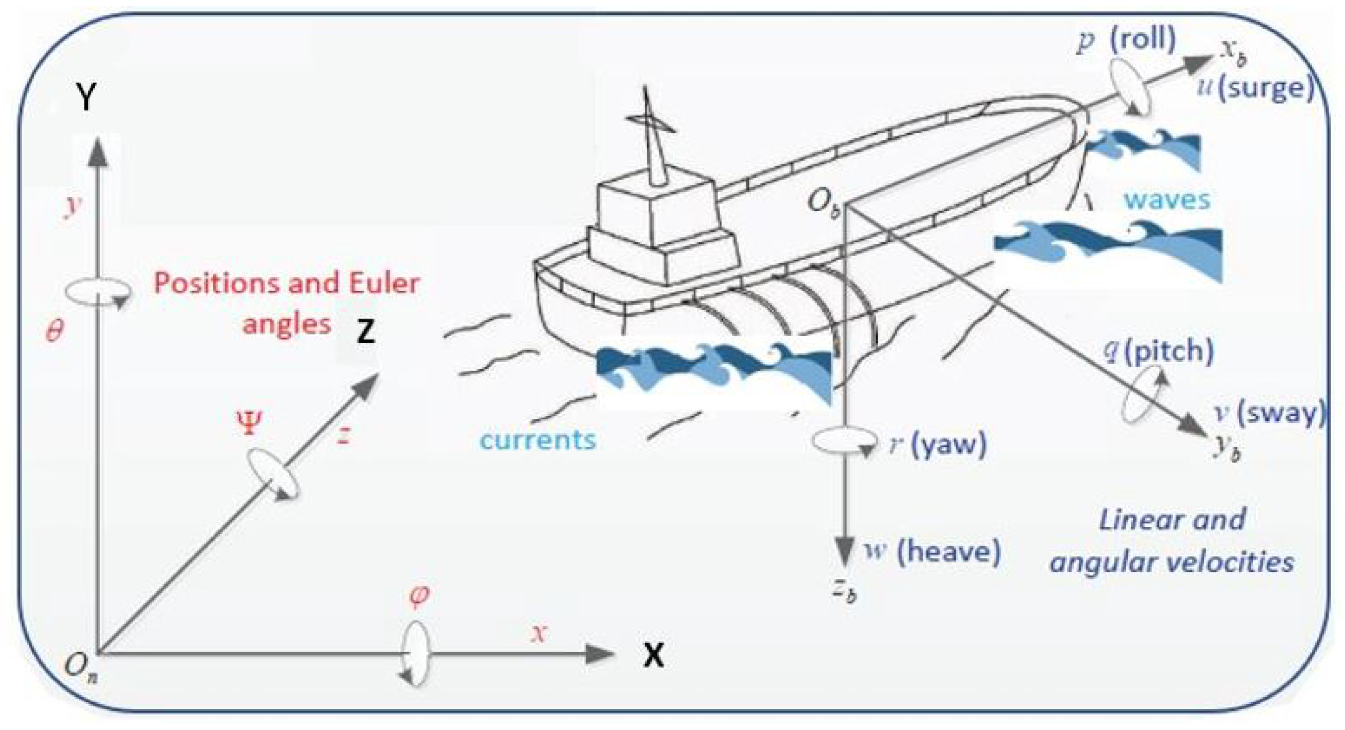
Figure 1. Ship motion in 6-DOF [24].
Applsci 10 07314 g001
Figure 2. Ship motion in 3-DOF.
Applsci 10 07314 g002
Figure 3. The flow-chart of the particle swarm optimization (PSO) algorithm.
Applsci 10 07314 g003
Figure 4. The position of ship q 1 in the x-coordinate.
Applsci 10 07314 g004
Figure 5. The position of ship q 2 in the y-coordinate.
Applsci 10 07314 g005
Figure 6. The orientation (heading) of ship q 3 (yaw angle ψ ).
Applsci 10 07314 g006
Figure 7. Integral square error (ISE) fitness values versus iterations.
Applsci 10 07314 g007
Figure 8. The position of ship q 1 in the x-coordinate with and without PSO.
Applsci 10 07314 g008
Figure 9. The position of ship q 2 in the y-coordinate with and without PSO.
Applsci 10 07314 g009
Figure 10. The orientation (heading) of ship q 3 (yaw angle ψ ) with and without PSO.
Applsci 10 07314 g010
Figure 11. The trajectories of the surface ship in the q 1 q 2 plane.
Applsci 10 07314 g011
Figure 12. The position of ship q 1 in the x-coordinate subject to disturbances.
Applsci 10 07314 g012
Figure 13. The position of ship q 2 in the y-coordinate subject to disturbances.
Applsci 10 07314 g013
Figure 14. The orientation (heading) of ship q 3 (yaw angle ψ ) subject to disturbances.
Applsci 10 07314 g014
Figure 15. The position of ship q 1 in the x-coordinate subject to disturbances.
Applsci 10 07314 g015
Figure 16. The position of ship q 2 in the y-coordinate subject to disturbances.
Applsci 10 07314 g016
Figure 17. The orientation (heading) of ship q 3 (yaw angle ψ ) subject to disturbances.
Applsci 10 07314 g017
Table 1. Time performance characteristics for the two controllers.
Time CharacteristicsModified ControllerOriginal Controller
q 1 Rise time(s)40.793559.0104
q 1 Settling time(s)457.76321062.9
q 1 Overshoot percentage41.004749.7733
q 2 Rise time(s)47.642346.8955
q 2 Settling time(s)480.8057765.8472
q 2 Overshoot percentage44.481859.0281
q 3 Rise time(s)5.46995.3337
q 3 Settling time(s)9.144541.6431
q 3 Overshoot percentage1.3724 (under)11.4531 (under)
Table 2. PSO algorithm parameters.
Parameter NameValue
Maximum iteration500
Swarm Size30
Self-Weight acceleration coefficient ( c 1 )1.494
Social-Weight acceleration coefficient ( c 2 )1.494
Inertia weight (w)0.729
kq1 range0.001–10
kq2 range0.001–10
kq3 range0.001–10
Table 3. Time performance characteristics for ISE and without PSO.
Time CharacteristicsWithout PSOwith PSO
q 1 Rise time(s)40.793517.0299
q 1 Settling time(s)457.7632277.9465
q 1 Overshoot percentage41.00475.6116
q 2 Rise time(s)47.642315.9123
q 2 Settling time(s)480.8057398.5471
q 2 Overshoot percentage44.48187.9774
q 3 Rise time(s)5.46993.4137
q 3 Settling time(s)9.14456.2746
q 3 Overshoot percentage1.3724 (under)0.6043 (under)
Table 4. Codes of sea state [39].
Sea State CodeDescription of SeaWave Height Observed (m)World Wide Probability (%)
0Calm (glassy)0-
1Calm (ripples)0–0.111.2486
2Smooth0.1–0.5-
3Slight0.5–1.2531.6851
4Moderate1.25–2.540.1944
5Rough2.5–4.012.8005
6Very rough4.0–6.03.0253
7High6.0–9.00.9263
8Very high9.0–14.00.1190
9ExtremeOver 14.00.0009
Publisher’s Note: MDPI stays neutral with regard to jurisdictional claims in published maps and institutional affiliations.