1. Introduction
The morphology of walking robots often resembles animals at a high abstraction level with the same number of limbs and placement of body parts. Bio-inspired robots that recreate animal mobility at a deeper level require close interdisciplinary collaboration between biologists and engineers. Potential benefits of developing such bio-inspired robots include improved movement versatility, dexterity, and durability, as well as other useful features such as using the same limbs for locomotion, grasping, burrowing and object manipulation. The improved understanding from studying animals’ embodied features and testing the differences they enable in robots can benefit research in both biology and engineering. The ability to recreate an animal’s embodied features in a robotic system is also a powerful demonstration of the feasibility of the current understanding of the animal’s functional principles. In this spirit, Laughlin, P. et al. [
1] describes biologists’ tasks as reverse-engineering studies: asking both how an animal trait works and why it is needed from functional and biological viewpoints. Subsequently, engineers can apply such insights to robots. Thus, biologists need to know what information is useful for the engineers, and engineers need to know what questions the biologists seek to answer.
Bio-inspiration can be an even stronger design approach in engineering, enabling the use of structures and subjects from nature as proof of concept and inspirational guides for creating novel robotic systems and devices [
2]. In robotics, bio-inspiration has been used to develop machines that fly like bees [
3], swim like salamanders [
4,
5], walk like stick insects [
6], climb like geckos [
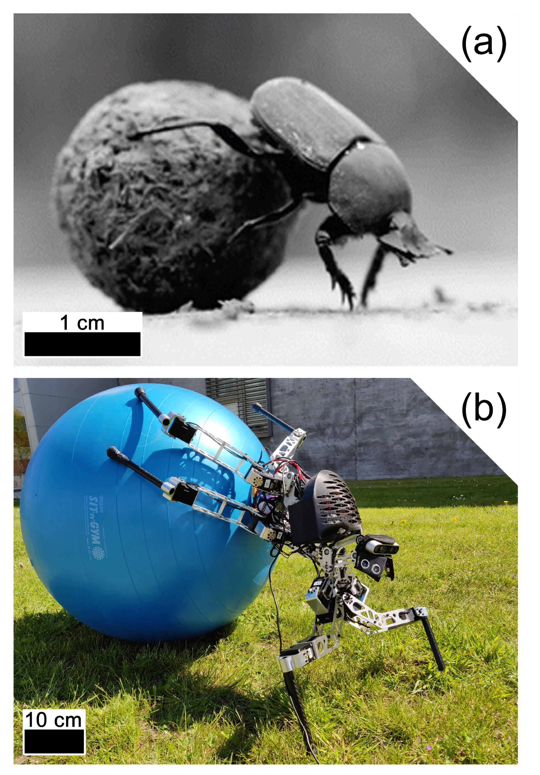
7] and manipulate objects like dung beetles [
8].
The domain of bio-inspired walking robots can be divided into two main categories:
template and
anchor models [
9]. A template model is a simplified replica of the animal’s morphology, which can help speed up development and highlight core principles of the morphology. Quadruped robots such as
Mini Cheetah [
10] and
Hubodog2 [
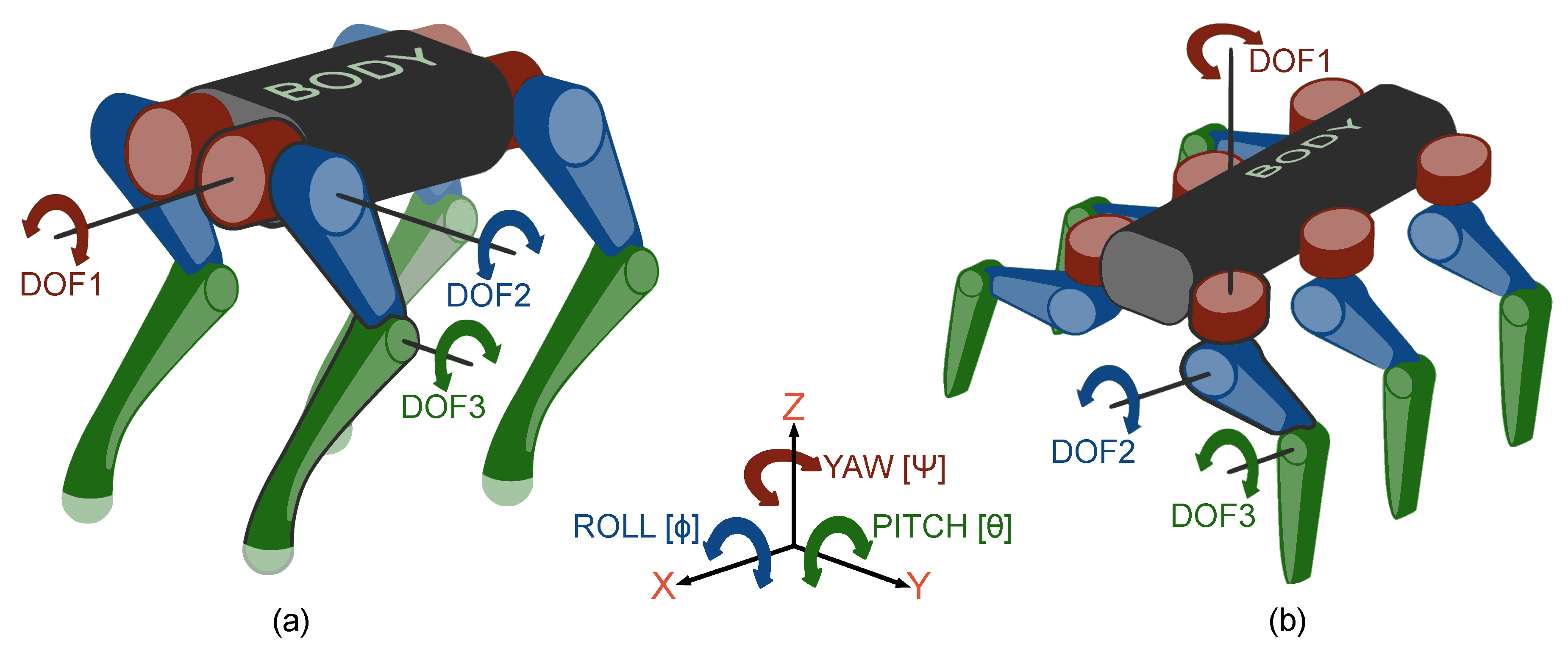
11] are examples of template models with a morphology supporting specific control principles and providing stable mechanics (
Figure 1a). An anchor model recreates the animal’s morphology more precisely to highlight its unique embodied features. For example,
Pleurobot is presented in [
4] as a quadruped anchor model inspired by salamanders, capable of mimicking both swim and gait patterns.
Most robots are somewhere on a spectrum between template or anchor, starting from prescriptive and simple template models and moving towards a more elaborate representation of the animals’ embodied behaviour [
9]. In [
12], the quadruped robot
Serval is presented as being in between the two model types with its template-like design and control that also has slight bio-mimic influences.
Hexapod template models such as AMOS [
13] and MORF [
14] often have similar kinematics, e.g., placement of motors, identical legs and leg joints that are angled to move the leg either vertically or horizontally (
Figure 1b). Having joint angles aligned with the yaw, roll, or pitch axes can simplify the development of the controller, as well as lessen the torque on the motor for the first degree-of-freedom (DOF1) during locomotion (
Figure 1b), which is quite different from insect morphologies, where the movement of one joint will influence the limb in all axes [
15].
The hexapod robots Lauron V [
16] and Hector [
6] are described as having legs angled in a similar way to stick insects. These examples of anchor models are demonstrating increased mobility due to having higher speed and kinematic flexibility. In [
15], the morphology of the dung beetle is measured and used as a model for a simulated robot, demonstrating that its anchor morphology exceeds both in standing on and manipulating ball-shaped objects.
Thereby investigating bio-inspired robot models can develop both biological and engineering hypotheses. However, this does require a formal interdisciplinary exchange of knowledge. It is not a standard in biological studies to focus on providing the measurements necessary for the morphological replication of animal models. Similarly, only a few engineering studies focus on investigating biological hypotheses.
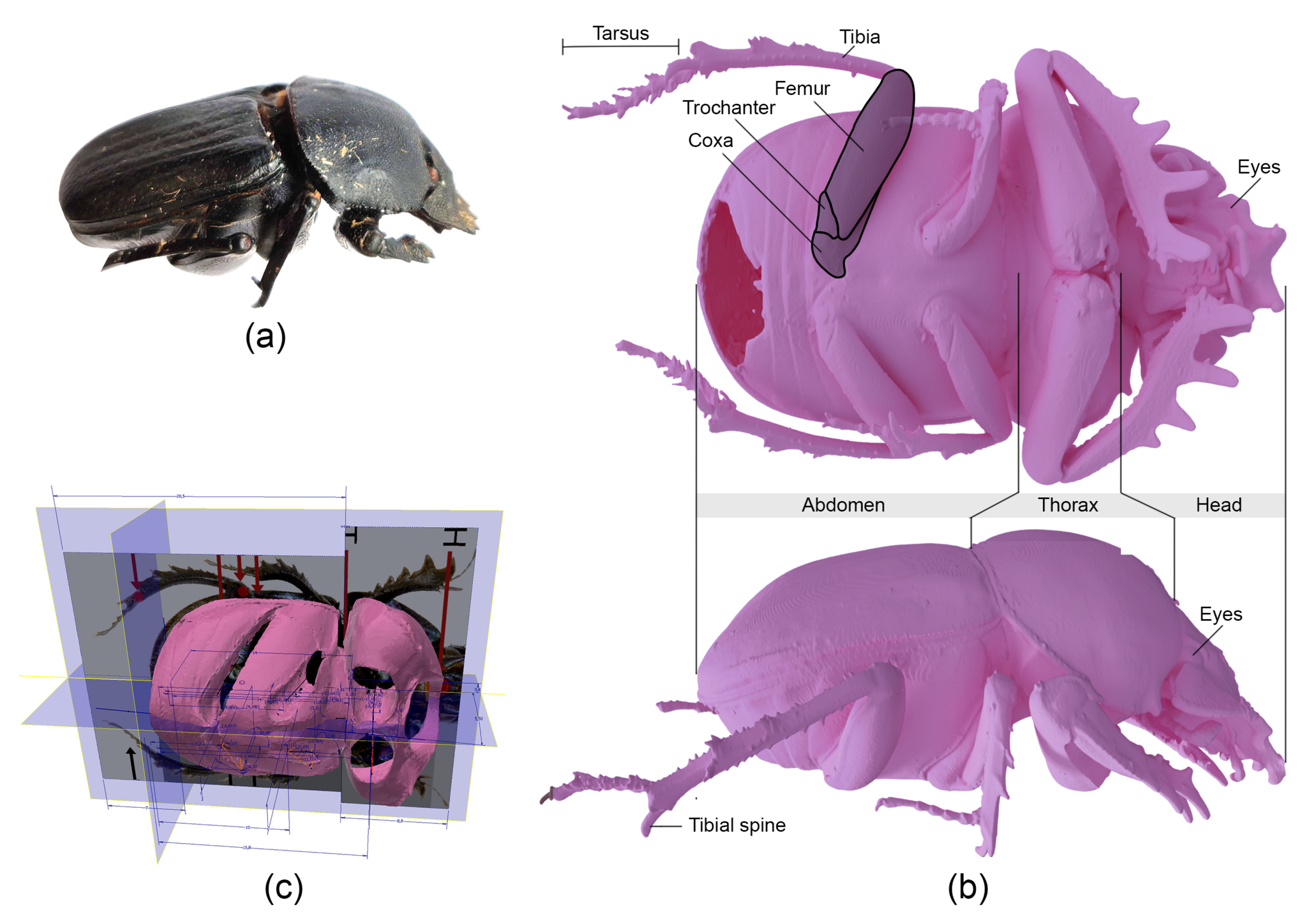
In this study, we present a framework for collaborations between biologists and roboticists and demonstrate its bio-inspired development process in a case study that models the morphology and functionality of the dung beetle species
Scarabaeus galenus (
Figure 2a) with the robot
ALPHA (
Figure 2b).
Subsequently, our simulations evaluate the bio-inspired morphology’s effect on ALPHA’s performance and compare it with a conventional hexapod’s performance (
Section 6). The ALPHA’s complex controller is not introduced in order to highlight the bio-inspired morphology’s base performance. Complex controllers have instead been presented by [
17,
18]. Simulations were used instead of the constructed prototype (
Figure 2b) to avoid invariances from physical tests and controller specific behaviours. As such, the analysis provides insight into the bio-inspired morphology’s base performance in terms of versatility, dexterity and durability, which can assist control engineers in developing better gait patterns in later works.
2. Framework for Developing Bio-Inspired Morphologies
A study of bio-inspired morphology begins with the investigation of an animal. As the biologists obtain sufficient functional and mechanistic understanding of the animal’s traits, the tasks move from analysis to modelling to synthesis, involving engineers and technicians. To guide this interdisciplinary process, we propose a problem-driven [
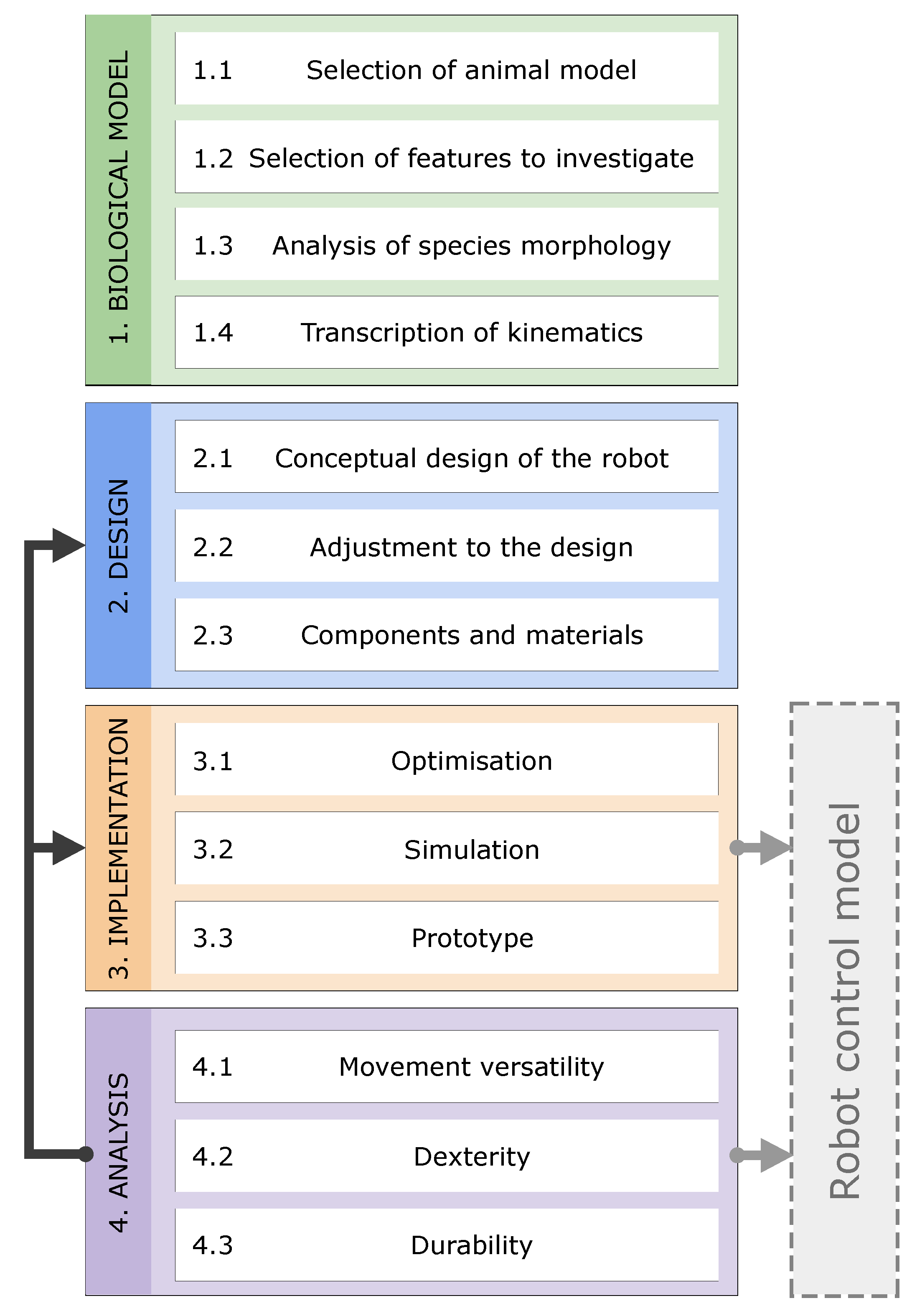
19] framework for developing bio-inspired morphologies for walking robots (
Figure 3). The framework uses elements from the hexapod development cycle proposed in [
20] while aligning it with other bio-inspiration processes [
19,
21] and integrating tasks related to studying and analysing the biological subject. Thereby, the framework’s structure matches other bio-inspiration models described in [
19], but also details the specific objectives related to the development of bio-inspired morphologies for walking robots.
This has four phases: 1. Biological model, 2. Design, 3. Implementation, and 4. Analysis. The first one primarily involves trained biologists, while the last three involve trained engineers; however, some overlap does occur in-between.
In phase (1. Biological model), the morphological data of a selected animal species are collected for engineers to use in the later design phase. The phase starts with selecting a species that is known to have features of interest for modelling and/or further study (1.1) The selection is based on the aim to (a) investigate specific features of the animal biomechanics, locomotion, behaviour, et., which are desirable to implement in robots, or to (b) investigate a biological hypothesis by using a physical robot model. Next, the feature(s) of interest to investigate is selected based on a desirable trait for a robot (1.2). Subsequently, multiple specimens of the selected animal species are measured (1.3). Different techniques can be deployed such as measuring joint positions with a 3D microscope [
15], CT scanning the animal [
4] or measuring the weight of individual segments [
15]. Phase 1 finishes by describing the kinematics of the animal (1.4). This is done by converting the raw surface model into an articulated 3D model or transcribing the degrees of freedom in a kinematic chain with dimensions. As mentioned above, it is necessary to measure multiple specimens to average the dimensions and to counter other variabilities among specimens (e.g., gender, age, injury).
In phase (2. Design), the biological model is used to guide the design of a robot model. The phase begins by developing a conceptual design of the robot with a focus on the desired features (2.1). The next step, Adjustment (2.2), identifies the features of the biological model that are not feasible and essential to recreate in the robot’s morphology. Thereby, 2.2 highlights unavoidable deviations between the biological model and robot, or rather, adjustments of the biological model for it to fit all robot components. For example, increasing the size of the transcribed morphology (1.4) might be necessary to fit all hardware components (2.3) and to place the actuators according to the joint axes. Finally, the robot’s hardware and materials are chosen (2.3). Critical to this phase is the close collaboration between biologists and engineers. This depends on the engineer learning enough about the biology and the biologist learning enough about engineering requirements and limitations to understand the fine details of the project, tasks with an often underestimated time consumption.
In phase (3. Implementation), engineers and technicians develop, construct, and assemble a prototype of the final version. The first step is to optimise the design (3.1), for example, to reduce the robot’s weight and the actuators’ load. Subsequently, software tools and physical models can be used to check if the leg design and scaling factor match the animal’s range of movement and that the motors have sufficient performance for the movements. Simulations of the robot are used to perform initial tests of the robot’s performance (3.2). Additional optimisations (3.1) might be needed to obtain mobility. Subsequently, the prototype is built as a physical robot (3.3). The developed simulation (3.2) or physical models (3.3) are used in phase 4 to investigate the morphology’s embodied performance. Finally, developed models may also be used to initiate the development of a robot controller in parallel with the following steps.
In phase (4. Analysis), the morphology’s static and dynamic behaviour is analysed in the context of the morphological and mechanical design. The analysis can support biomechanical hypotheses and guide control engineers on how to improve gait patterns and reduce fatigue-inducing impulse from foot strikes. A template model can be used as a reference to indicate the differences that the anchor morphology induces. Performance parameters relevant to investigate, in regards to morphology influences, are
movement versatility (4.1) like stride length or stepping height,
dexterity (4.2) like reachable poses or limb configurations [
15] and
durability (4.3), like impact mitigation or ease of strengthening mechanical components. The durability of walking robots is often improved by enhancing actuation and control technologies [
22,
23]. However, durability can also be improved if the morphology better distributes mechanical stress, and lowers the frequency and amplitude of impulses during gait, which ultimately improves mechanical fatigue life [
24,
25].
Additional iterations of development may be necessary in cases where the analysis results are found to be insufficient. Here, it is either necessary to return to further optimize the robot structure (3.1), or change components (2.3), adjust the design (2.2) or perform substantial changes to the concept (2.1).
In the following sections, this framework is followed for the development of the robot ALPHA that imitates the dung beetle species
Scarabaeus galenus and compares the resulting design with a more standard template model. The template model uses the same components and leg design, but in a conventional hexapod structure (
Figure 1b).
4. Phase: Design
Developing walking robots has numerous challenges, as design parameters can be inversely related, and require detailed optimisation and a wide network of suppliers for the hardware [
20]. For example, the design needs to be mechanically robust while having minimal mass, and the components need to be compactly assembled while the leg movement should not be restricted. The framework for developing bio-inspired morphologies (
Figure 3) provides a guide to handling these challenges. The framework also enables the robot controller to be developed in parallel with the hardware.
4.1. Conceptual Design of the Robot
Prior to modelling the robot, it is essential to establish a component and material architecture (
Section 4.3) optimized for the robot design. For example, the walking robot’s size, shape, dynamics and assembly are, to a high degree, shaped by their actuation system and the torque density [
23]. Additionally, structural materials and components are chosen to have high strength and stiffness, while maintaining a small size and mass, in order to minimize leg inertia and to improve the overall dynamics [
23]. Hence, the selected components influence the conceptualization of the robot.
Laser-cut sheet metal and composites are an optimal mechanical framing system for the robot, as they are cut to exact sizes, quick to produce in-house, and therefore enable swift investigation of various ideas and prototypes. Using sheet materials requires three-dimensional parts to couple the sheets together with spacing in between, in order to gain stiffness and reproduce the joint angles of the biological model.
Three versions of the robot were constructed to obtain a feasible and robust design: a mock-up (I), a functional model (II) and the ALPHA prototype (III). The mock-up is based on crude dimensional assumptions and was rapidly constructed to obtain a physical reference model for insight in the robot size and design challenges. It consisted of 4-mm, laser-cut plywood and 3D-printed couplings that could attach the plywood pieces at correct angles to create an enlarged version of the biological model.
The functional model tested if it matched the scaling factor [22:1] of the biological model (
Section 4.2) can hold all the pre-selected components while still allowing full mobility of the spinal joints and legs. The scaling factor was multiplied with the transcribed kinematics of the biological model (
Section 3.4) to obtain the robot’s dimensions. Subsequently, Autodesk Inventor and the add-on PointLinker by CoolOrange was used to import the enlarged dimensions from Excel into the CAD files. The imported dimensions then defined the shape of the frame, legs and joint couplings (
Figure 5). Laser-cut, 3-mm aluminium sheets, carbon fibre tubes, and 3D-printed motor replicas and couplings (
Section 4.3) were used to create the functional model.
The functional model’s precision in recreating the biological model (
Section 3) was evaluated by first comparing (I) the legs’ kinematic
origin points in relation to the scaling factor and (II) the angles of the TC and AC joints (
Table 1) where the the origin points is defined by the coordinates for the intersection of TC and CTF joint axes. Hence, the functional model’s dimensions matches those of the
S. galenus (
Table 1), with the exception of the front legs’ CTF joint position (
Section 4.2). The lengths of the leg segments were compared separately.
4.2. Adjustment to the Design
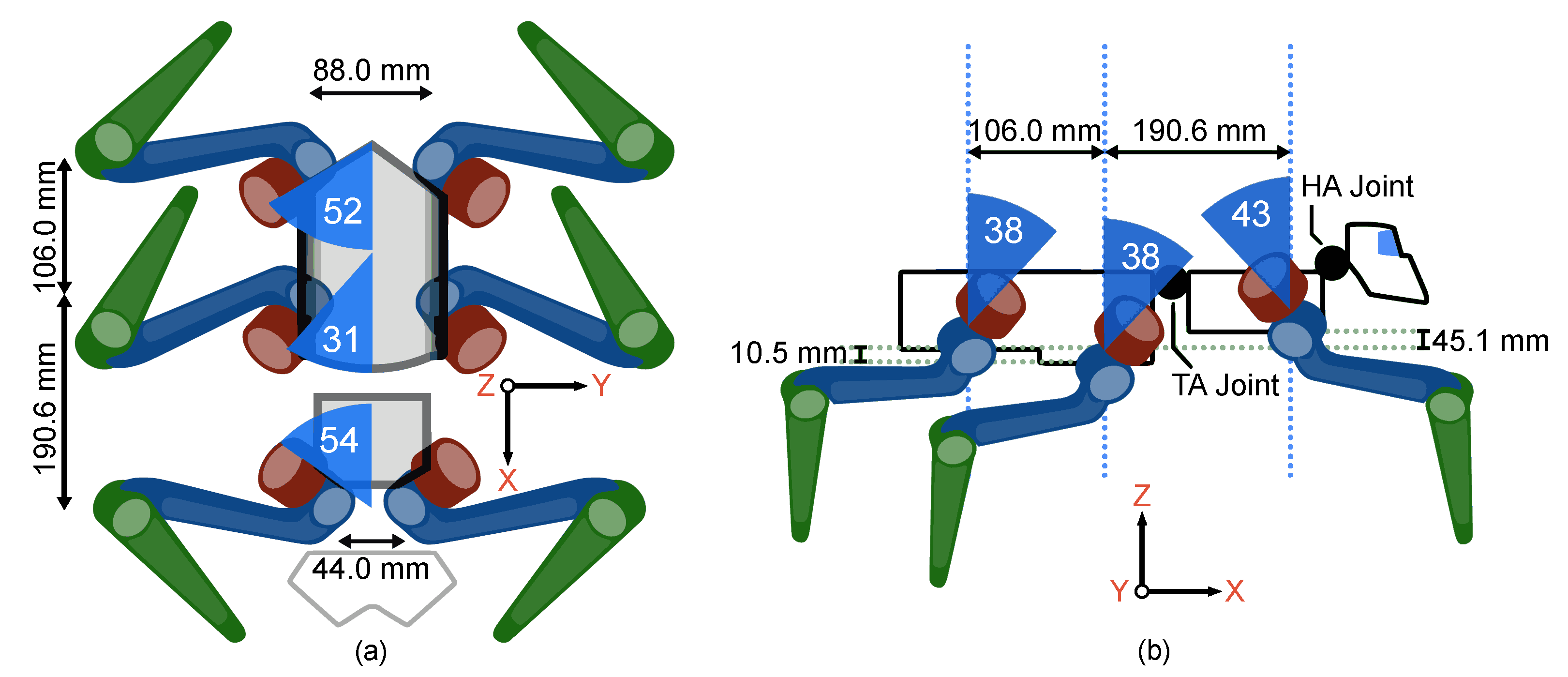
Robot morphology followed the biological model’s morphology (
Section 3.4), except in four respects: (I) a
difference in size, (II) an
offset of front legs’ origin point of 20.2 mm in the X-direction and 36.0 mm in the Z-direction (
Table 1), (III)
merging the CT and TF joints into the CTF joints, and (IV) a
simplification of the foot design (end-effector).
The robot design was developed according to the features of interest (
Section 3.2), and therefore did not aim to reproduce the biological model’s size. The technical challenges in downsizing all mechanical components, actuators, controllers and batteries would be too daunting and infeasible for the investigation. Instead, the robot was developed with a scaling factor that enlarges the
biological model sufficiently to house all components and permit the use of industrial components: off-the-shelf motors, screws, bolts, cables, batteries and controllers. Among these, motors have the largest influence on the robot’s size, shape and dynamics, and are typically selected first based on torque density, efficiency, mechanical robustness, integrated sensors and compact size [
22]. The functional model showed that it was possible to fit all components compactly into a 22:1 scale model of
S. galenus’s and recreate the full biological movement range.
The only dimensions where the robot morphology deviates from the enlarged biological model are the x and z-value of the front legs’ origin points (
Figure 5 and
Table 1), and merged CTF joints (
Section 3.4). The origin points of the robot’s front leg are positioned higher than the biological model, as the beetle’s front legs have a different morphology to its middle and hind legs. The coxa of the
S. galenus’s front legs are considerably larger than the ones of the middle and hind legs, which positions the front legs’ CTF joint further from the TC joint (
Figure 4). Therefore, the TC and CTF joint axes of
S. galenus’s front legs do not intersect but are shifted instead. However, the selected components (
Table 2) could not feasibly recreate the shifted joint axes in the functional model or prototype. The beetle’s foot has, among other structures, the tarsus and tibial spine that provides traction. An engineering study of these mechanisms is postponed. Instead, a round rubber foot was chosen as a simplified design with good traction characteristics.
Hence, the (I) scaling factor of 22:1, (II) moved x and z-value of the front legs’ origin points, (III) merged CTF joints, and (IV) simplified foot design are considered acceptable adjustments for the prototype when considering the scope of the study, mobility and compact design.
4.3. Components and Materials
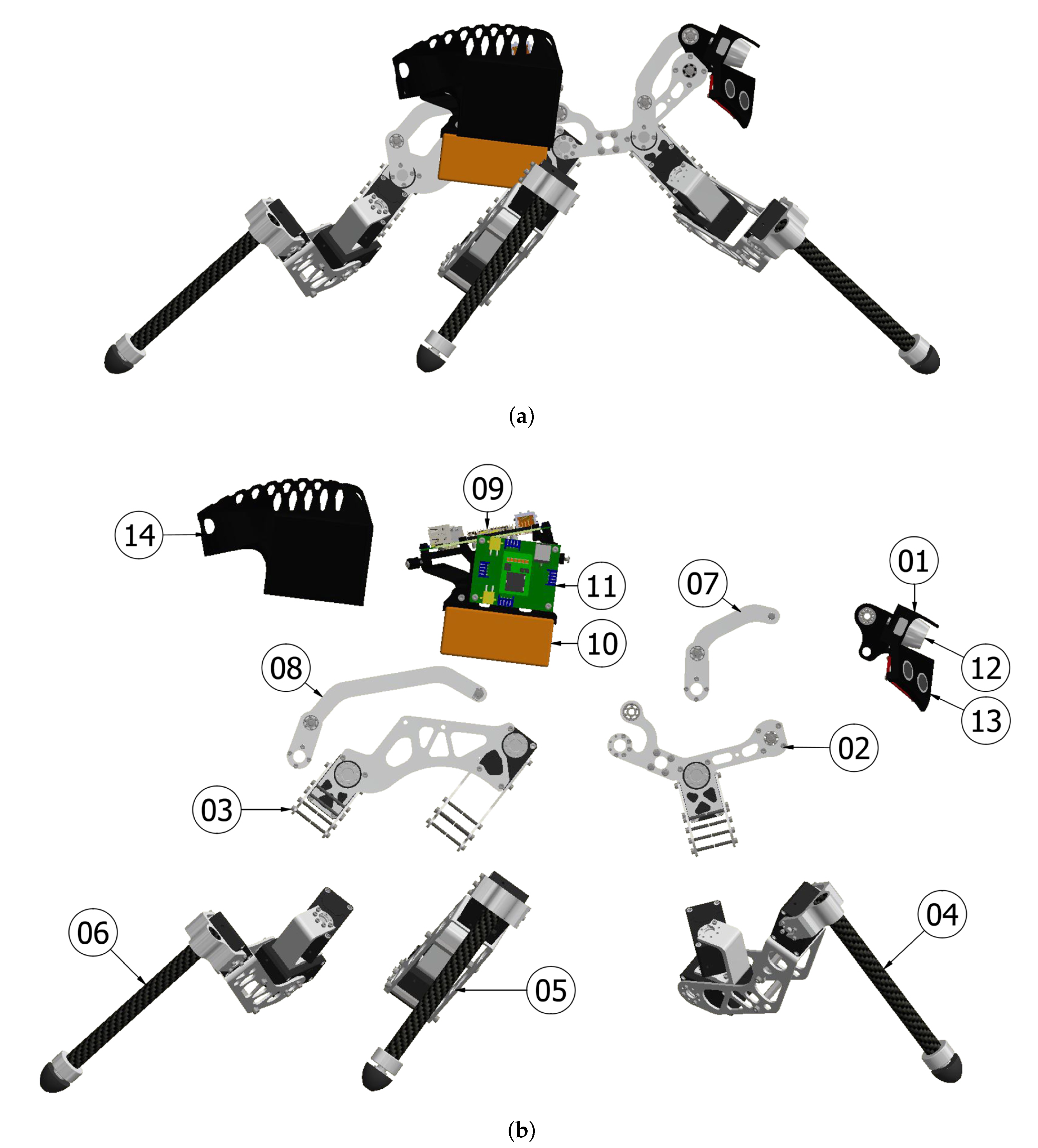
The motors were selected according to torque output, speed, mass, equipped sensors and price. Here, the Dynamixel motor series XM430-W350-R from Robotis was an optimal choice, due to their high torque output of 4.8 Nm, low weight of 0.082 kg, good torque density of 58 Nm/kg, fair speed of 57 RPM, current sensors for impedance control, drivers, price, and Robotis’s production capability. Furthermore, the threaded flanges on all sides simplified the robot design, and enabled the motors to also function as the mechanical coupling points for the frame

and leg components

(
Figure 6).
Laser-cut aluminium 5754 sheets were suitable as framing for the robot’s body and femur links, due to their fast production, low cost and high strength. CNC milled aluminium 6061-T6 was better where higher stiffness, intricate details and threads were needed, such as the joint couplings

and pushrods

for the HT, TA, FT and CTF joints. Carbon fibre tubes were ideal for the tibia links, as they lower distal mass and inertia, as well as allow easy attachment of a greater variety of foot mechanisms and sensors.
High battery energy density (Watt-hour/kg) was crucial to extending the operational time at a specific weight. Two LiPo 1850 6S 22.2v battery packs from MaxAmps were found to have the highest specific energy on the market at the current time (
):
6. Phase: Analysis
The following section presents the analyses of the ALPHA according to phase 4 (
Figure 3), where the anchor model’s performance was tested alongside a template model to highlight their differences. Hence, the developed leg structure (
Figure 7) was simulated for both morphologies in CoppeliaSim to make their performances comparable. Simulations were used instead of the prototype (
Figure 2b) to avoid invariances from physical tests and controller specific behaviours. The leg configurations were also tested, while separated from the robot to remove inertias induced by other legs during movement. Throughout the analysis, the template leg was set to match a conventional hexapod structure (
Figure 1 and
Figure 9a), while the anchor leg configuration matched the beetle’s right front leg (
Table 1 and
Figure 9b).
CoppeliaSim’s integrated inverse kinematics-based control algorithms were used to control the legs’ with static- (
Section 6.1 and
Section 6.2), or dynamic positions with stance and swing phases (
Section 6.3). The dynamic tests consist of (1) a stance phase where the foot follows a predefined straight trajectory on the ground, and (2) a swing phase, where the foot is lifted and follows a predefined curved trajectory. In both phases the TC-, CTF-, and FT-joint movements are calculated with inverse kinematics.
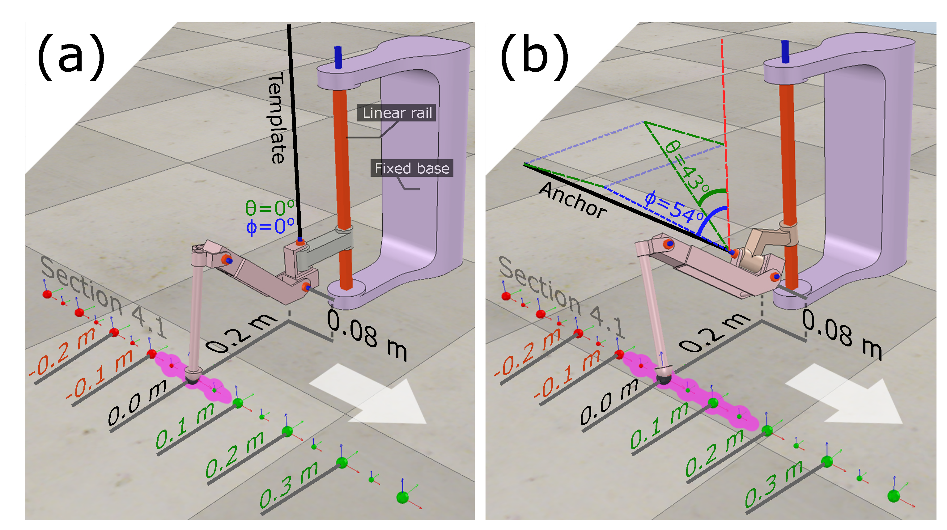
The legs’ origin point was positioned 0.08 m above-ground and held in place by a vertical linear rail (
Figure 9). Each leg was loaded with 2.0 kg, which is similar to the worst-case scenario described in
Section 5.2. The performances of the anchor’s hind and mid legs may be approximated from the front legs’ results, as the legs have the same joint distances, similar mass, and a mirrored angulation (
Table 1 and
Figure 5).
6.1. Movement Versatility
To investigate the models’
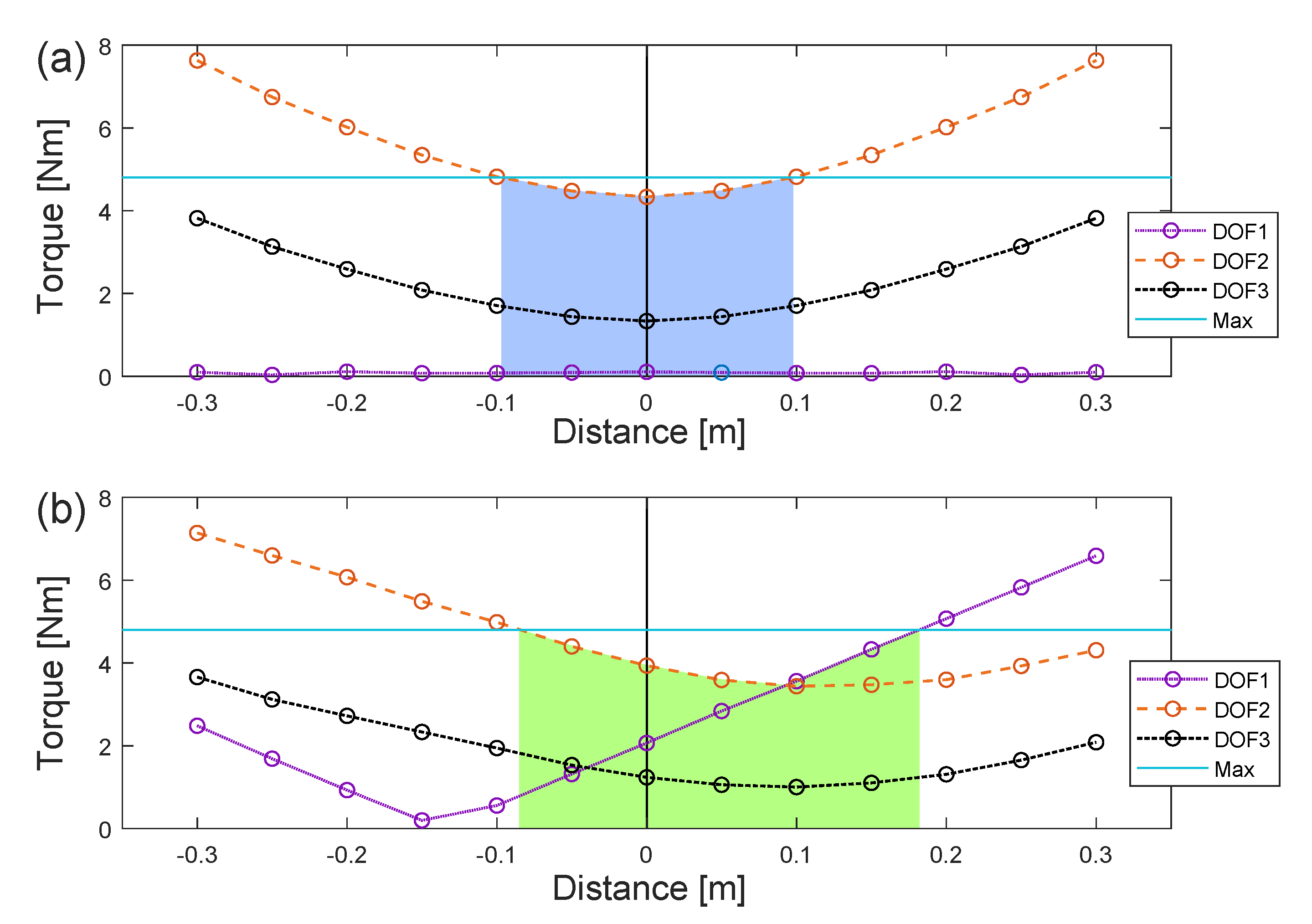
Movement versatility, it was tested how far forward and backward the end-effector of the legs can reach on a flat surface before any of the motors reach the maximum torque output of 4.8 Nm and are overloaded (
Figure 10-max line). This highlighted the step ranges that can be used in future gait controllers. Therefore, the legs were set to step in a line 0.08 m below and 0.20 m lateral to their origin point (
Figure 9), which creates a path where the legs do not collide with the rest of the robot.
Figure 9 represents static stances, and therefore do not include additional torques from when the leg was moving the body forwards or backwards.
The template morphology can perform steps of 0.18 m before being overloaded, while the anchor morphology can perform steps of 0.27 m (
Figure 9-pink line and
Figure 10-filled area). Hence, the anchor morphology is capable of performing 50.0% longer steps. Meanwhile, this causes a higher total torque output for the anchor morphology (
Figure 11) and, thereby, a higher power consumption.
6.2. Dexterity
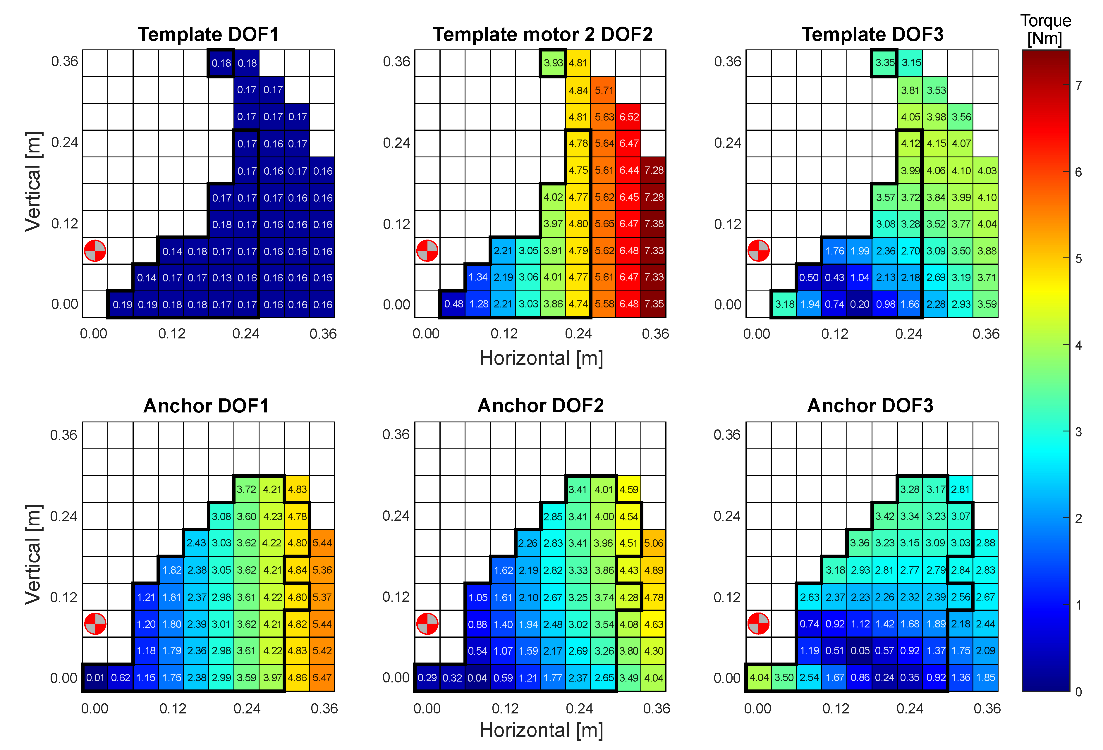
Simulations were performed on both morphologies to investigate their
Dexterity (2) in terms of ability to step onto and traverse obstacles and objects. The legs’ end-effectors were set to step in a para-sagittal plane that intersects the leg origin points. The reach varied in the longitudinal distance (x) and height (y) of the plane (
Figure 12). The resolution of the steps was set to 0.04 m in both directions.
It is found that the anchor morphology has a better reach in both the proximal and distal direction, as well as a generally higher reach (0.28 m). The template morphology was limited by the motor connected to the second-degree-of-freedom (DOF2), which was disproportionately more heavily loaded than the other motors. Meanwhile, the motor for DOF1 remains nearly unloaded. While the template morphology can reach the highest isolated point (0.36 m), this reach is then practically unusable as the point is unconnected with the remaining usable manipulation area. The template morphology was able to use 22 of its 48 reachable positions (45.8%), while the anchor was able to use 43 of its 54 reachable positions (79.6%), which provides the anchor with 95.5% broader usable reach.
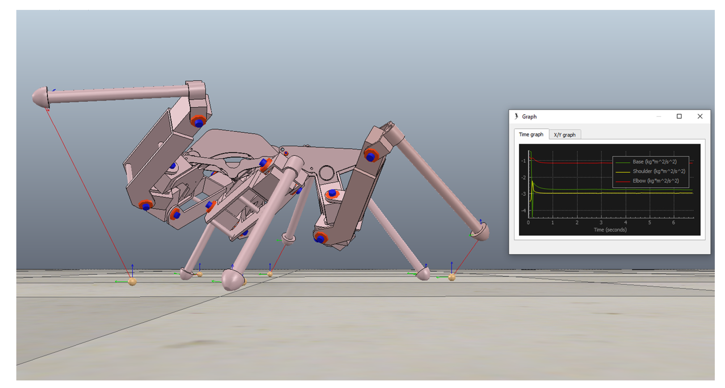
6.3. Durability
Motor torque impulses from rapid accelerations and foot strike impacts may also create fatigue-inducing damage to the mechanical components. Therefore, the motor output torques during steady gait were investigated for the template and anchor morphology (
Figure 13). Here, the template morphology proved to reach higher torque levels than the anchor morphology and overloaded the motors by up to 18.37%.
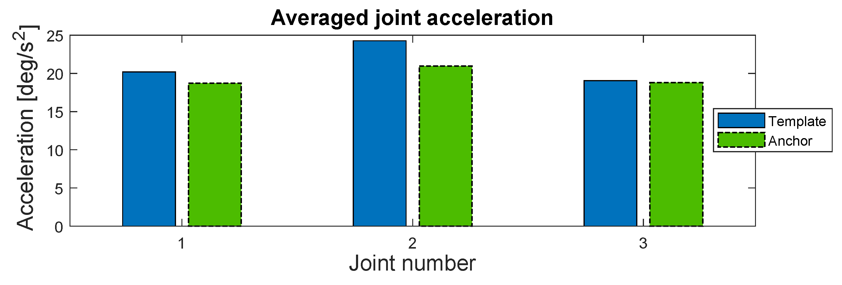
Subsequently, the step dynamics were analysed relative to their maximum range (
Figure 10-filled area). The anchor morphology’s longer step length results in a 21.1% lower stepping frequency (0.15 Hz) than the template model (0.19 Hz). When averaging each legs’ total motor acceleration over 50 s, it was found that the motors of the anchor morphology had a 7.9% lower general acceleration than the template morphology; where the DOF1 motor was 7.3% lower, the DOF2 motor was 13.6% lower, and the DOF3 motor was 1.3% lower (
Figure 14). The lower torque impulses and acceleration level helps decrease fatigue and increase motor life.
7. Discussion
The framework for developing bio-inspired morphologies proved to be a great help as a tool for developing the ALPHA, and ensured a prototype that replicates the biological morphology to a high extent (
Table 1). In [
15] the morphology of dung beetles was applied to simulations to investigate its advantages in hexapods. However, by using bio-inspired development, a greater level of detail in replicating the biological morphology has been achieved with the ALPHA hexapod (
Figure 2b), together with a more quantitative investigation of the insect morphology. Further research of the framework in the near future will be needed, including more use cases. Here, the presented framework can be used as the basis for further research into bio-inspired morphologies.
An analysis investigating performance parameters (
Table 4) showed that the anchor morphology of ALPHA created an improved performance compared to a template morphology. The simulated template leg was limited to shorter steps (
Section 6.1), as its DOF2 motor quickly reached the maximum output, due a poor distribution of loads between the three motors (
Figure 9). The DOF2 motor carried 2.7 to 3.0 times the load of the DOF1 and DOF3 motors combined. The DOF1 motor carried nearly no load, as the leg’s mass force vector was parallel to its rotary axis. Meanwhile, the anchor leg’s improved distribution of torque loads on all three motors enabled 50.0% greater reach before either the DOF1 or DOF2 motor were overloaded. Here, the DOF2 motor was the first overloaded motor when reaching in the posterior direction, while the DOF1 motor was overloaded in the anterior direction. Hence, the anchor’s improved distribution of torque loads on the motors enables greater step lengths, more movement options in the path, and thereby a greater
movement versatility (
Section 6.1).
From
Figure 9 it can be derived that the anchor’s stride length can be further increased with 0.07 m of forward reach for every newton meter that the DOF1 motor’s torque capacity is increased. This can be continued to the leg’s maximum forward reach of 0.30 m, when the DOF1 motor output is increased to 6.59 Nm (+37.3%). It is plausible that the robot’s volume and mass will not be drastically increased by upgrading the DOF1 motors. Furthermore, this highlights an advantage of the anchor morphology. It is more feasible to upgrade the anchor’s usable step length than it is to upgrade the template’s. The anchor obtains full reach by improving the DOF1 motors’ torque output to the 6.59 Nm, while the template needs to improve the DOF2 motors to 7.63 Nm (+59.0%). Furthermore, it is harder to upgrade the DOF2 motors, as they are positioned on the legs’ moving frame, where larger volumes will restrict movement, and greater masses increase inertia. The DOF1 motors are more proximal than the DOF2 motors and attach directly to the body structure, which makes it easier to change them without affecting the leg movements. A trade-off for the anchor’s higher mobility is slightly higher power consumption (
Figure 11).
In addition, the anchor morphology’s improved torque distribution enables 95.5% greater reach, by utilizing a greater amount of its forward work envelope (79.6%) than the template morphology (45.8%) (
Figure 12). The template morphology was able to reach the highest point of 0.36 m. However, it is prevented from practically using this isolated position, as the DOF2 motor will be overloaded as soon as the leg starts to pull downwards from the position, thereby moving the leg in a forward curve (0.24 m and beyond). The positions throughout this curve will overload the DOF2 motor, as the end-effector reaches too far from the origin point. It can be considered that the load on the front legs might be reduced in some positions and angles of the hexapod body, which can enable greater reach. However, the anchor morphology still has a greater reach in those positions. Hence, the anchor morphology with its improved
dexterity can better utilize its workspace and overcome obstacles than a template morphology.
The anchor morphology helps to protect the robot from fatigue-inducing impulses that, over time, will damage mechanical components, such as gears, bearings and structural components, which ultimately lowers the robot’s service life [
23,
32]. For example, the anchor morphology has an overall lower acceleration level of 7.9% during gait, while the most noticeable difference is the 13.6% lower accelerations of the DOF2 motor. The anchor morphology’s longer stride length lowers the frequency with 21.1%, which contributes to the previously mentioned reductions.
The lower step frequency of the anchor morphology also minimizes the number of impulses from foot strikes per distance travelled. Mechanical shock dampeners and/or control strategies can be used to mitigate impulses from foot strikes [
32], however, lowering the overall number of impacts per distance travelled lowers the robot’s general exposure to impacts and contributes to the extended service life. Subsequently, impact mitigating strategies can be implemented as an addition to lower the detrimental effects even further. For example, impedance control can be implemented to mitigate the effects of impacts during movement [
23].
Compared to the template morphology, the anchor morphology also lowers the torque output of the motors during gait (
Figure 13) and better prevents motor overload. Hence, the anchor morphology provides a greater
durability based on the improved torque distribution (
Figure 13) and less stress on mechanical components (
Figure 9 and
Figure 12).
8. Conclusions
This paper proposed a framework for developing bio-inspired morphologies for walking robots and presented a case study that used the framework to develop a dung beetle inspired robot, ALPHA. The framework proved to enable the development of a walking robot with advantages over conventional hexapod designs in key performance parameters such as movement versatility (1), dexterity (2), and durability (3). In addition, a greater replication and knowledge of the system was achieved through structured development and a strong input of biological morphological data.
Simulations proved that the obtained anchor hexapod morphology has important advantages over a template hexapod morphology, which are obtained by the roll and pitch angle of the first joint in each leg (
Table 1). For example, the template morphology was limited to shorter step lengths of 0.18 m before it was overloaded, due to a disproportional load on its second motor. Meanwhile, the improved distribution of torques on the anchor morphology’s motors enabled 50.0 % longer steps. Likewise, it was found that the anchor morphology has a 95.5% better dexterity and ability to reach, step onto and traverse objects and obstacles.
In addition, it was found that the anchor morphology’s performance is easier to further upgrade and improve upon than the template morphology. These advantages are applied to all pairs of legs: front, middle and hind legs. Finally, it was found that the anchor morphology has slightly higher power consumption as a trade-off.
This study’s subject will in future studies be further researched in three directions:
Utilizing the data from the analysis (
Section 6) to further optimize ALPHA’s controller, as well as highlight other advantages of the anchor morphology;
Investigating other embodied features that are influenced by the morphology, and therefore suitable to be implemented in the framework’s phase four (
Section 6);
Developing mathematical models that may further optimize the anchor’s control in regard to parameters such as torque distribution, dexterity, durability and speed [
8,
33].

 ,
, 


 and leg components
  (Figure 6).
 for the HT, TA, FT and CTF joints. Carbon fibre tubes were ideal for the tibia links, as they lower distal mass and inertia, as well as allow easy attachment of a greater variety of foot mechanisms and sensors.
 and abdomen
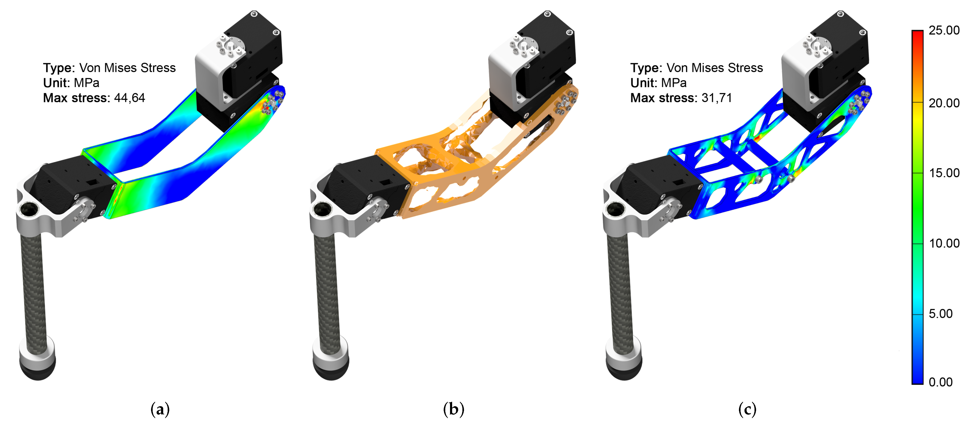
 designs to increase the robot’s total power density (Figure 7b). Topology optimisation indicated the optimal placement of the PCB spacers (Figure 7b,c), which noticeably stiffened the structure and lowered the maximum stress level from 44.64 MPa to 31.71 MPa (29.0%). In total, topology optimisation reduced the frame by 180 g, which was a mass reduction of 32.0 % for all the frame components and 4.7 % of the ALPHA’s total mass.
 design differs from those of the middle
  and hind legs
  , which imitates the dung beetle and potentially improves forward motion, climbing and object handling. Furthermore, the prototype’s femurs were improved to also replicate the original curved shape of S. galenus femurs (Figure 7). These bends enabled increased the flexion of the CTF joint before the femur collided with the body.
 and
and  , were used to translate the motors’ rotation to the HA and TA joints. The middle
  which could be one of the following options: Raspberry PI 3B+, Intel NUC7I7DNBE or a customized FPGA board. A 3D printed PLA shell ⑭ protects the electronic cabinet.


 head,
head, 


