Article

Soft Underwater Robot Actuated by Shape-Memory Alloys “JellyRobcib” for Path Tracking through Fuzzy Visual Control

by
Christyan Cruz Ulloa
*,
Silvia Terrile
and
Antonio Barrientos
*
Centro de Automatica y Robotica (UPM-CSIC), Universidad Politecnica de Madrid, 28006 Madrid, Spain
*
Authors to whom correspondence should be addressed.
Appl. Sci. 2020, 10(20), 7160; https://doi.org/10.3390/app10207160
Submission received: 30 August 2020 / Revised: 27 September 2020 / Accepted: 4 October 2020 / Published: 14 October 2020
(This article belongs to the Special Issue Bio-Inspired Robotics II)

Abstract

:
Recent developments in bioinspired technologies combined with the advance of intelligent and soft materials have allowed soft robots to replicate the behavior of different animal species. These devices can perform complicated tasks such as reaching or adapting in constrained and unstructured environments. This article proposes a methodology to develop a soft robot called “JellyRobcib” inspired in morphology and behavior by jellyfish, using shape-memory alloy springs as actuators (as bio-muscles). Such actuators can move the jellyfish both vertically and laterally by applying closed-loop fuzzy and visual controls. Additionally, Computer-Assisted Designs and Computational Fluid Dynamics simulations have been carried out to validate the soft robot model. The results show that the robot movements are very close to the morphological behavior of a real jellyfish regarding the curves of displacements, speeds and accelerations, after performing several experiments for autonomous movement: vertical ascent, lateral movements and trajectory tracking, obtaining an accuracy of ±1479 cm and repeatability of 0.944 for lateral movements for fuzzy visual control. Furthermore, thermal measurements were taken throughout a given path, allowing the generation of temperature gradients within the underwater environment for monitoring purposes.

1. Introduction

Recent developments in intelligent materials have made it possible for them to be used as actuators because of their outstanding characteristics. For example, shape-memory alloys (SMA) present a reduced size, lack of mechanical elements, or the ability to modify their mechanical properties (elastic modulus, electrical resistance) by applying currents during milliseconds to generate movement. In the robotics field, the use of intelligent materials for actuation and mainly SMA, have allowed the implementation of soft robots capable of replicating the movement of animals. On the other hand, conventional mechanisms are complex to miniaturize and heavy to be introduced in aquatic environments. The main contribution of this work is the development of lateral displacements in the soft robot (“JellyRobcib”) actuated by SMAs, taking as a starting point a computational analysis, since the most representative prototypes actuated with SMA only have vertical movement, without prior exhaustive analysis, and the presented robot can follow a defined trajectory. Before the robot’s implementation, computational analysis was carried out using Computational Fluid Dynamics (CFD), body deformations and a heat transfer simulation to verify the thermal maps performed from acquired data. This project integrates different disciplines to achieve the pursued objectives: vision, control, electronics and mechanical systems.
This paper is structured as follows: in Section 2, state-of-the-art and previous works are shown. This is followed by the Materials and Methods in Section 3, which has been divided into subsections showing the design, analysis and implementation. In Section 4, the specific results that correspond to each of the processing steps explained previously are included. To conclude, Section 5 summarizes the main findings.

2. State-of-the-Art

Previous works show different technologies developed until today following an evolutionary line based on the feedback of previous works and research. Nonetheless, a detailed speed and pressure analysis has not been found, nor an analysis of reactions generated based on the displacement of fluids that causes the movement of the jellyfish, or lateral displacements executed with SMAs. Thus, the present work starts from a theoretical structured model to develop a bioinspired robot actuated by materials with shape memory and the application of the robot to carry out tasks such as thermal monitoring in underwater environments. This state-of-the-art paper focuses on soft underwater bioinspired robots and especially on jellyfish prototypes. At the same time, it is important to highlight the importance of previous studies on the pulsed-jetting system; in [1], numerous examples are mentioned.

2.1. Soft Underwater Bioinspired Robots

Soft materials allow soft bioinspired robots to replicate movements of animals in both terrestrial and marine habitats. In the case of the underground environment, some of the most significant prototypes are worm-like robots [2,3,4], caterpillars [5], snakes [6,7], insects [8], and bat wings [9,10]. In the case of the underwater environment, research focuses on the development of prototypes that replicate the movement of fishes [11,12,13,14,15], octopuses [16,17,18], and jellyfishes [19,20,21,22]. Other interesting prototypes are the quadruped robot that walks underwater [23], the Manta swimming robot [24], biomimetic underwater robots based on dielectric elastomer actuators [25], or rajiform swimming robot [26]. All these robots present different actuation systems that can be summarized into three main categories: variable length tendon, fluidic actuation, and electroactive polymer (EAP) [27]. The first category (variable length tendon) comprises robots actuated with traditional tendons and motors [28] and robots actuated with shape-memory alloy (SMA) [29,30], the type of actuation examined for this paper. Each of the actuation systems present advantages and disadvantages. SMA is characterized by simplicity, noiseless actuation, and low weight, among many other merits. On the other hand, this material also presents some disadvantages, such as low energy efficiency, complex motion control, and low operational speed [31]. EAP actuators present advantages similar to those of SMA actuators, and they are probably one of the best choices when prototypes are significantly small [32]. Fluidic actuation, by contrast, presents high operation speed, easy motion control, and can generate greater forces. Principal disadvantages include weight, dimensions, and noise.

2.2. Evolution of Projects Developed and Actuation Systems

One of the first jellyfish prototypes, developed by the University of Kagawa (Figure 1a), used the conductive ionic polymer film (ICPF) as an actuation system [18]. It generates contractions using an articulated mechanism. The next representative development was realized by the Virginia Center of Investigation that created a jellyfish using SMA named “Robojelly” (2011). It has a polyethylene coverage, inspired in the Aurita Aurelia species. When the SMA is activated, it produces a reaction with the water that generates hydrogen that helps the displacement [19]. Along the same line, a jellyfish robot based on a mechanism of spring retraction was implemented (Figure 1b) [20]. It was controlled by servomotors and had a silicone body, capable of generating a unilateral contraction. Another prototype based on the same operation principle, but actuated by elastomers producing an expansion to expel the water, is presented in [21]. Within the most recent developments in 2018, the University of Atlantic Florida implemented a jellyfish operated by air microvalves, which is capable of generating a lateral movement limiting airflow to four of the eight tentacles (Figure 1c) [22]. In 2019, a jellyfish operated by SMA capable of moving vertically, thanks to a central SMA, was developed (Figure 1d) [23]. One of the last works developed is a soft jellyfish with a diameter of 3 mm actuated through an external oscillating magnetic field, capable of generating movements with a degree of vertical inclination of the body. Table 1 shows complementary information on additional related projects carried out under this same line of research [24,25].
Despite various developments focused on jellyfish with different performance, no great progress was made in obtaining lateral movements especially in the control algorithms. Furthermore, the implementation of control systems to generate coordinated movements through defined trajectories, especially using SMA, has not been emphasized enough. Additionally, previous works have not focused on specific applications for this kind of robots. These are relevant aspects that this research addresses.

3. Materials and Methods

This section describes the methods used to develop the underwater soft robot. It shows the robot model developed based on the movement and anatomical study of the jellyfish species “Chrysaora hysoscella”. After that, the computational simulations of CFD, pressures and material analysis to verify the correctly operation of the robot before its implementation are shown. The requirements for implementation are described below: body measurements were taken based on the dimensions of an adult stage jellyfish (22–30 cm) (the Chrysaora hysoscella species commonly known as “aguamar”, chosen because there is information published to make reference to), because it seeks to replicate the biomimetic behavior of the jellyfish, with a speed in the range of 2.5–2.8 cm/s and a weight of 110 g, including the actuation system. Actuation system: electrical and visual control system.

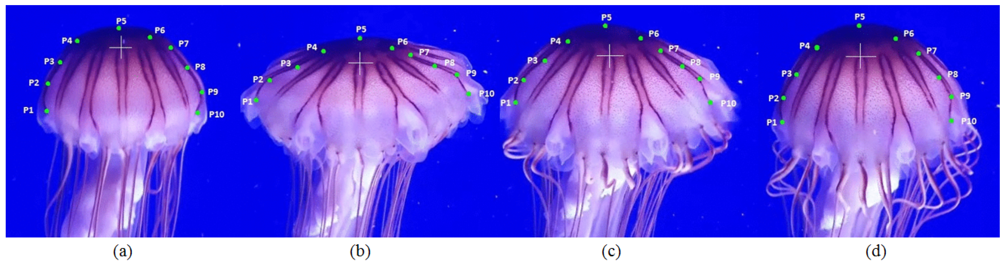
3.1. Design and Implementation of the Jellyfish Body

Among the main characteristics of the jellyfish is the reduction of turbulence caused by the robot movement, which implies using a low-invasive propulsion system [41]. Taking that into account, the robot model has been inspired by a jellyfish, mainly due to its soft body, small size and propulsion system due to periodic contractions.

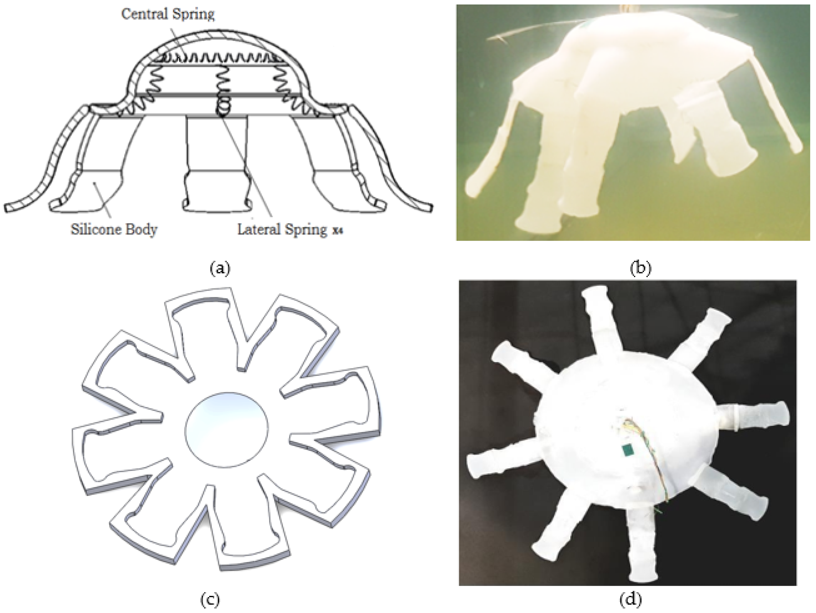
3.2. Computer-Assisted Design (CAD) Model Design and SMA Actuation

One of the main systems of actuation within the soft robotic is the SMA, which is an alloy of nickel and titanium (hence the commercial name Nitinol), developed by the Naval Ordnance laboratory in the United States in 1962. After the material deformation and taking advantage of the change of state in the composition of its crystalline structure because of the change in temperature, the material recovers its original form. From this date, research and prototypes have been carried out using SMA wires as actuators instead of conventional engines [42]. The importance of using SMAs as actuators lies in their small diameter, quick action and low weight, which facilitate the generation of complex movements in small spaces, which with conventional mechanisms, servomotors or other intelligent materials, such as piezoelectric materials, will be complex to replicate [43,44].
The CAD model developed for analysis and simulations was generated in Solidworks based on a behavior study for jellyfish species Chrysaora hysoscella, which is typical of the Mediterranean Sea and has several representative characteristics of most jellyfish (bell delimited and pronounced tentacles) [45]. Figure 2 shows the analysis carried out on an adult-sized Chrysaora jellyfish (diameter of approximately 23 cm), for which 10 uniformly distributed points were established along its bell to analyze the evolution of the extreme areas (4 points) and middle zone (6 points) during the process of relaxation and contraction.
The described movement consists mainly of two stages: the first one of relaxation, Figure 2a,b, at which stage the central bell is extended, and a second phase of contraction, which happens in a range of reduced time with respect to relaxation (around 21% of the relaxation time); the contraction phase is from the state shown in Figure 2c,d, which is in the range of 0.7 s and allows it to expel the fluid inside the bell, achieving movement. The points in Figure 2 [P1–P10] represent distributed points on the surface of the jellyfish body and have been placed to have a visual reference of the states of the body during the contraction and relaxation phases.
Additionally, it has been identified that the tentacles contribute with an additional fluid displacement that generates vertical movement.
The implemented actuators have been selected based on their desirable characteristics for the movement, specifically to generate rapid contractions, which are their reduced size and their weight which does not represent a significant load, as well as the characteristics of the Nitinol used: activation temperature 50–65 °C + −5 °C, diameter 500 and 375 μm, alloy material: nickel titanium, acquired in “smartwires” [46].
The robot body has been made with a highly flexible Ecoflex® silicone base, and it has an average diameter of 22 cm. Figure 3a shows a central cross-section of the model, and Figure 3b is a photograph of the final prototype. In the first state, a mold (Figure 3c) made with a 3D printer in ABS plastic generated from the jellyfish CAD model was made to develop such tests as silicone elasticity resistance and temperature resistance of the SMA + silicone set. Finally, the body of the implemented robot (Figure 3d) had to be dried for 2 h in a flat glass surface, and during this process, the central SMA was added, as well as the tentacles, which were taken from the mold.
The robot consists of 5 SMA spring actuators placed so that one SMA is in the center of the body (350 m i c r o n s ) with a ring shape of an 80 mm diameter and 4 lateral SMAs (500 m i c r o n s ) of 75 mm length are located radially, anchored in the center and on the periphery with 90 degrees of separation, as reflected in the cross-section of Figure 3a. In this way, the controller can determine the degree and the time of contraction to produce the relaxation and contraction to expel water.

3.3. Design and Placement of the Actuators

The SMA manufacturing process is based on winding the SMA wire in a screw and fastening it with nuts at the ends, then it is introduced into the oven where it reaches 600 °C, for 15 min, prior to a subsequent cooling process (Figure 4a), thus obtaining the SMA with the spring memory. The subjection of the 4 lateral SMAs was carried out externally, i.e., SMAs had been previously encapsulated (Figure 4b) with a thin layer of Ecoflex Silicone, leaving them completely sealed, and with the cables for the control board, their anchorage to the jellyfish body was made by means of thin metallic joints that cross the SMA cover layer and the body, being fixed by pressure. The central SMA, on the other hand was fused to the body, where it was placed during the drying process, laying the cables for control on the outside.

3.4. Computational Simulation

Three types of analysis were carried out to verify robot functionality prior to its implementation; these analyses allowed evaluation of, at first instance, the behavior of the material against the SMAs’ contraction. The second analysis was based on the volume displaced by the jellyfish during the contraction, and the third analysis was complementary to the previous ones and had the purpose of evaluating the pressure generated during the contraction inside the jellyfish bell and determining if the pressure is necessary for a positive displacement.

Material Analysis

A simulation of the jellyfish body material behavior was carried out (Figure 5) to evaluate the displacement generated and the amount of water that can be evacuated with each contraction. The amount of water displaced was used as data for the CFD analysis. The SMA spring return to its extended form is due to the design of the tensioned silicone body. After the contraction is generated and the temperature in the SMA is reduced, its state becomes malleable, so that it is extended by the silicone body itself.
Using Equation (1) [47,48] that relates the shear modulus of the SMA material (G) [N/m2], SMA diameter (d) [m], variation of displacement during contraction (x) [m], springs’ turn diameter (D) [m] and the number of spring turns (N), we could calculate the maximum force that the central SMA will make during the application of contraction.
F = G d 4 x 8 D 3 N
The equation only allows “estimating” the force, due to the complexity of modeling the entire actuation system. Although the stress strain produced is directly considered, the term in the equation “G” relates to both types of stress, since both are in function of the Y (Young’s modulus) as established by Pons [42]. When working with Nitinol, there is shear stress and normal stress, but since both efforts are partially present at the same time, it is considered that G = Y. The calculated previous force is represented by a cyclic force exerted by the central SMA and was applied to the CAD model (the force is represented by the brown arrows for the two cases in central Figure 5b and lateral Figure 5c), which is assigned the parameters of the material (Ecoflex Silicone 00-30): viscosity 300 cps, shore hardness 00–30, breaking strength of 900%, tear resistance of 38 p l i (6654 Nm/m), Shore hardness 00-, specific volume (26 c u . i n / l b ), maximum temperature 450 °F (232 °C) [49]. Simulation results show a maximum displacement of 70 mm in the central bell after contraction, which represents a volume of displaced water equal to 557 cm3. The zones with a red color range represent the zones of greater displacement, produced in the bell by the central SMA.
Figure 6 shows the behavior of jellyfish modeling; Figure 6a shows the contraction of the jellyfish bell for a reference of 10 cm, where the system response is extremely fast, achieving the reference in the first 2 s, and keeping it constant because of the fuzzy controller. For its part, Figure 6b shows the response of the force generated by the SMA to a 5 N reference signal; here, the sudden increase of the force is due to the sudden contraction of the SMA.
Figure 7 shows a comparison of the diameter variation for two contractions. During the first 0.7 s, it quickly shrinks in size due to the force of contraction exerted by the SMA. After that, it returns to its relaxed state again while the SMA is cooled. The curve shown in red differs slightly from the red one, mainly due to the data capture and filters applied in the vision system.

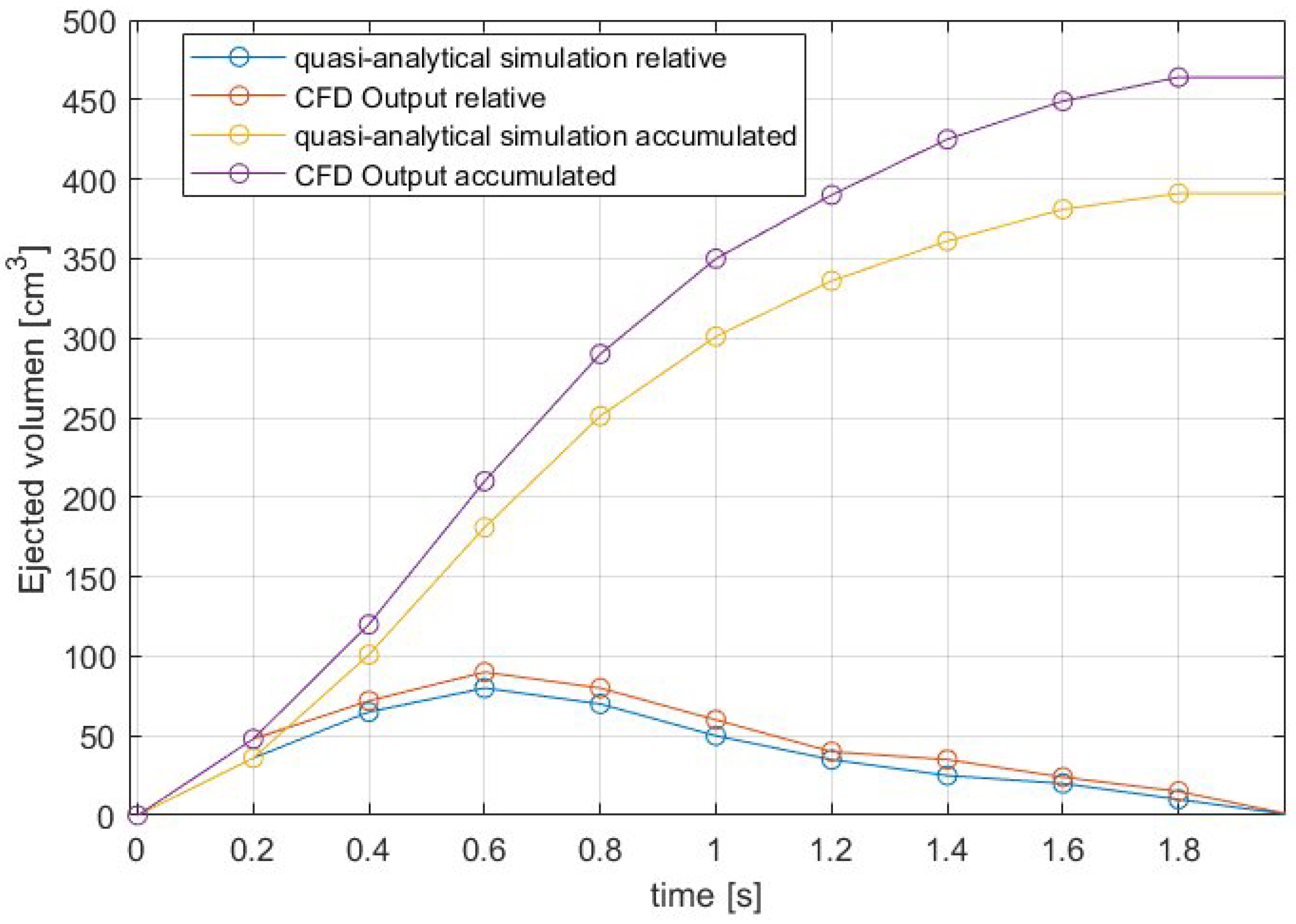
3.5. Computational Fluid Dynamics

The Jellyfish displacement is produced by its propulsion system generated by contractions. When these happen, their body generates a vortex, which is forcefully expelled, and produces a thrust that generates a reaction that drives it forward. To keep the movement constant, a series of pulsations must be generated. To validate the geometry model, all forces involved in the displacement of a body in the water, such as drag coefficient, added-mass coefficient and Reynolds number, are analyzed [50]. Together with the data obtained from the CFD, they allow evaluation of the instantaneous acceleration produced by the contraction and determine if jellyfish can advance [45].
During the development of the simulation, gravity has been used as an active parameter, because its use implies the action of buoyancy. Figure 8a,b shows the fluid displacement (water) during the vertical and lateral contraction respectively represented by spheres, where there is a variation in the sphere color according to the velocity generated during the process, the spheres being red for high-speed areas and blue for negative velocity areas. The accelerations are shown with lines in Figure 8c,d for vertical and lateral contraction, respectively.
The verification of simulation is performed based on Equation (2) [51], which evaluates the average acceleration in order to determine if a positive displacement is generated. This expression involves the water jet thrust under the hood ( T i ) [g·cm/s2], the drag force ( D i ) [g·cm/s2], the weight (W) [N] and the effective mass of the jellyfish ( E i ) [g]. This equation does not consider the presence of tentacles, because of the complexity of modeling for them; for that reason, a known model was considered to represent the most relevant part of the body (around 92% of the body is modeled as a bell shape). The calculation without including the tentacles shows that there will be a positive displacement, while the simulation corroborates that tentacles generate an additional impulse because of the positive vortices generated at the ends after each contraction. In this study, the robot presents a slow motion, and the positive feedback on thrust associated with “added-mass variation” is very small and has not been considered [52].
A m = T i D i + W E i
which are calculated, respectively, from the expressions: Equation (3) for ( T i ), Equation (4) for ( D i ), Equation (5) for ( E i ) and Equation (6) for ( α i ) [51,53,54,55].
T i = A v . α . j i 2
D i = 1 2 . ρ . u i 2 . π . h i . d i 4 . C D , i
E i = V b , i . ρ . 1 + α
α i = 0.5 d i h i 1.4
The variables involved are bell hole area ( A v ) [cm2], water density at 25 °C ( ρ ) [g/cm3], fluid velocity ( j i ) [cm/s] instant jellyfish speed ( u i ) [cm/s] jellyfish bell height ( h i ) [cm], jellyfish diameter ( d i ) [cm], drag coefficient ( C D , i ), volume inside the jellyfish bell ( V b , i ) [cm3] and the added mass ( α ). Equations (7)–(9) were used to calculate the previous values:
j i = 1 A v d V s , i d t
For Equation (3), where j i [cm/s], is the jet speed at time i, A v [cm2] is the umbrella’s whole area and V s , i [cm3] is the instantaneous volume under the umbrella.
u i = x i + 1 x i 1 2 t
In Equation (4), where u i [cm/s], is the speed at time i, x [cm] is the position for the respective time and t [s] (time)
C D , i = 24 R e n
For Equation (5), C D , i , is the drag coefficient, R e the Reynolds number and “n” depends of the value of R e , with n = 1 if R e less than 1 and n = 0.7 if 1 < R e < 500.
Based on these expressions, an acceleration equal to 3.38 cm/s2 has been determined, similar to the CFD result of 3.8 cm/s2 (Figure 8c). Therefore, the displaced fluid, the result of the contraction, will generate an acceleration greater than zero, and consequently, the displacement will generate progress and not regression.
Figure 9 shows a comparison between the displacement of the given volume for the quasi-analytical simulation (modeled on Equations (2)–(9)) and the CFD output volume for a contraction, where the accumulated volume was included as reference to see how it changes during the contraction. Figure 9 shows the displaced volume at each moment and the total accumulated volume for each defined case. Thrust modeled with CFD is higher from the analytical model, because viscous effects associated with the formation of the vortex ring and added-mass-variation effects are neglected in the analytical model.

4. Results

4.1. Data Acquisition and Control System

The experimental system shown in Figure 10 allows the execution of robot movements, acquisition of location data and monitoring of thermal data. It consists of 6 stages. Stage 1 is responsible for acquiring the images of the robot through a wireless camera (in a real situation, in deep waters, there is a project developed and tested by the Monterrey Bay Aquarium Research Institute (MBARI) based on a vision system. This control system tracks marine animals with an autonomy of 89 min, and it was tested with the Plychogena medusa) [56], which are sent to the central computer.
Stage 2 corresponds to the control interface for movement control and establishment of virtual points. Data monitoring is carried out with the temperature sensor that the robot carries on board, and the sensor was placed on the robot’s top because according to the CFD, the displacement of fluids in this area is less than in any part of the body, acquiring a more reliable measurement. Then, through the vision system (Stage 3), which applies object segmentation and digital image processing techniques, the robot is located inside the aquatic environment.
In Stage 4, based on the current position and virtual path points, errors are calculated and provided to the fuzzy controller that through Stage 5 (power stage) supply the current in a controlled manner to contract the SMAs. The potency card shown has been designed and implemented based on the power requirement to handle currents of up to 6 Amps with 36 Volts.
Finally, Stage 6 corresponds to the robot within the aquatic testing environment and the execution of movements.

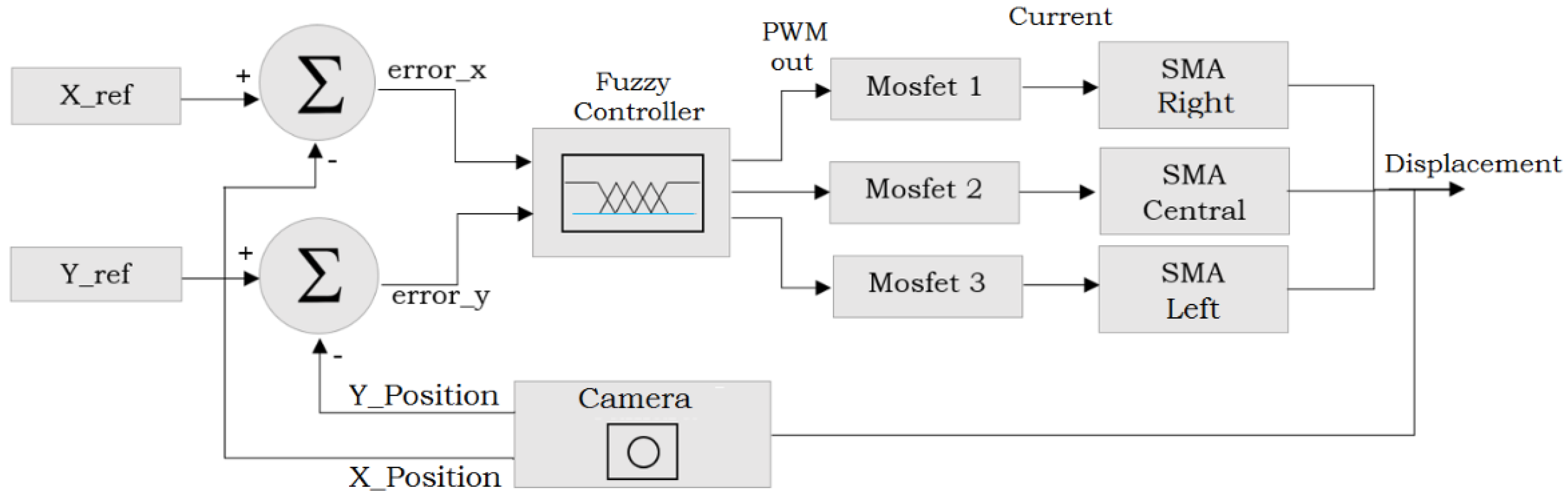
4.2. Monitoring Interface and Fuzzy Control System

For the development of movements, a MATLAB interface was developed through which the robot is monitored, and different parameters are calibrated (Figure 11). It has two modes of operation. The first one is a manual method and allows the robot to be teleoperated, through the threshold configuration for PWM value and image threshold.
The independent movements are executed by the operator using the buttons on the panel (forward, backward, right, left, ascent), and the temperature values are acquired as required by the user; the results of the manual movement were captured on video and examined in MATLAB.
The second mode is autonomous and requires the establishment of virtual points placed so that they form a monitoring path. Figure 11 shows the location of four virtual destination points (P1, P2, P3, P4) so that the robot forms a square trajectory and performs thermal monitoring in that area, with an established uniform sampling time of 500 milliseconds.
A fuzzy control system was implemented because a control (PID) is not feasible due to the lack of a precise model because the body does not have a rigid structure, and due to the nonlinear and discrete relationship between SMA control and resulting contraction.
The control loop (Figure 12) has as its input the virtual destination point consisting of two coordinates ( x r e f , y r e f ). These values (given in millimeters according to the previously performed calibration) are subtracted from the current values of the robot position given by the vision system, determining an e r r o r x and an e r r o r y , respectively. These values are sent to a fuzzy controller with two inputs and generate three outputs, whose rules are detailed in Table 2. The variables in the table are defined as ( e + ) positive error, ( e ) negative error, (z) zero, ( S M A R C L ) right, center and left SMA actuator, respectively.
The PWM output values have been raised based on the observation and analysis of the robot’s behavior through manual operation, determining that pulse width modulation values greater than 200 (78% of the cycle) generate a quick contraction response in the SMA, where H i g h P W M corresponds to 255, M e d P W M is 175 and n u l l P W M is 0, in a range of [0–255] of the duty cycle.
Based on the fuzzy conclusion generated from the rules, the respective output of the PWM is generated, toward one of the Mosfet in potency card: (Mosfet 1) for displacements to the right, which acts on the respective lateral SMA, (Mosfet 2) for vertical displacements, which acts on the central SMA in the form of a ring and (Mosfet 3) for displacements to the left, by means of the respective lateral SMA.
The maximum peak current operated by the potency card is up to 6 Amps, which is applied for a maximum time of 500 milliseconds—enough time to produce the molecular state change in the SMA, returning to its initial form of contracted spring, generating the displacement of water by compressing the respective area in the jellyfish body.
After that, there is a recovery time of 2 s, in which the jellyfish passes to the state of relaxation; during this time, the SMA, with the help of the low water temperature (24 °C), reduces its temperature and changes its state again, before executing the closed-loop control again.
The controller is conditioned by external programming to correct the errors “x” or “y” one by one, since according to the CFD analysis, the impulse generated after each contraction would be lost if it is performed in a combined lateral way and vertical or first lateral and then vertical. Therefore, the best option was to correct first in “x” then in “y” or conversely.

4.3. Movement Execution

The proposed experiments consist of establishing trajectories through virtual points through the developed interface, so that the robot can follow them due to the motion controller and perform periodic temperature measurements in order to generate thermal maps and analyze the parameters of the jellyfish movement. The tests and results are available in the annexed video link (Appendix A).
The environment of tests to carry out the experiments was a pool with measures of 1.30 × 1.50 × 2.50 m. Table 3 shows in its three sections the results of the three types of movement tests and movements carried out, as well as the main variables measured during the execution of the monitoring movements.
Figure 13, graphically shows the result of the visual system location, where the points in red show the jellyfish centroid for each moment, while the blank areas correspond to the jellyfish segmented and superimposed for each moment, so that the path of passage is defined.
Over the trajectory in Figure 13a–c, the points established for the path are shown, all starting from P1. In Figure 13a, an ascent movement has been made starting from the pool bottom and a destination point at the top; Figure 13b has its starting point on the left side and concludes in the right area; and Figure 13c shows the lower right central area of the pool and begins its trajectory towards the established trajectory points that conclude in the upper right.
Table 3 contains three subsections: a (vertical movements), b (lateral movements), and c (trajectory composed. Tthe results of different representative movement tests are shown in Figure 13, emphasizing the measurement of times, number of contractions of the SMAs involved, speeds and average accelerations, for trajectories made based on the establishment of virtual destination points. In this way, several individual tests were carried out with different destination points for each case.
A future research line proposed for the SMA control is the control loop feedback through temperature (currently performed through the vision system) to generate inclined movements with the jellyfish, in order to keep the SMA contracted for long periods of time without generating short circuits that damage the control board or the power card.

4.4. Experimental Results

The results of the kinematic parameters of experiments developed to validate the controller and movement of the jellyfish are shown. Data concerning speed were filtered using the Savitzky–Golay method. in Sections E and F for Figure 14 and Figure 15, red points represent data captured by the vision system at each moment, and the blue curves were used to represent the peaks of data with a higher value produced by contractions. Experiments developed are shown in Appendix A.
Figure 14 shows vertical movement developed to travel a distance of approximately 1 m, Figure 14F shows the speed peaks generated with each contraction (22 in total) and Figure 14D shows the ascent path, in which after each contraction there is a slight increase in the ascent, which is due to the propulsion generated after the expulsion of the water. Figure 14E shows a small variation of the x speed after each contraction. Figure 15 shows horizontal movement to travel a distance of approximately 25 cm, Figure 15E shows as red rectangles the electrical pulses to produce the contractions (5 in total) and as blue curves the speed peaks and Figure 15F shows the acceleration, where the peaks coincide to the instants where the contractions were executed.

4.5. Thermal Maps Generated through Path Tracking

One of the possible applications for the Soft Jellyfish Robot proposed is to monitor not only temperature but also other environmental variables (pH, contamination (turbidity)). Temperature was chosen to demonstrate this due to its ease of management and the fact that it is reversible, not contaminating the water and thus allowing us the opportunity to repeat the experiments without having to change it; additionally, this is a low-cost robot. Thermal maps are a representation of the monitored data.
During the trajectory journey, through the virtual points given by means of the interface shown in Figure 11, temperature measurements were carried out at different points along the path that traveled with a sampling interval of 500 milliseconds, to subsequently generate a thermal map of the area, based on the temperature gradient and the focused position of each measurement in an instant. To carry out these tests, boiled water (around 90 °C) poured from the test pool top was used, so that a heat source was generated that disperses and allows the water temperature to be modified uniformly.
The average time required to travel a trajectory at an average speed of 2 cm/s is 52.3 s; during this time, a constant flow of water was maintained from the top with a manually reduced flow, which is why it reaches the lower part with a temperature of around 33 °C in the lower areas.
The movement of the jellyfish bell affects in part the uniform distribution of the water, but the sensor has been placed on top just where the movement of the water is greatly affected.
Thus, Figure 16a refers to a map generated from real measures taken by Robotic Jellyfish with a thermal focus on the upper central part, while for Figure 16b, it has two thermal sources of dispersion in the upper corners. Water was poured in each spot with a high temperature at 90 °C, and the graph shows the temperature transfer tendency to the lower temperature zones, reaching a maximum of 50 degrees and a minimum of 25 in the areas where there was no temperature transfer.

5. Discussion

5.1. Biomimetic Behavior and Movements

To make this analysis, the vertical jellyfish displacement has been taken as a reference, since it is the movement typically performed by the species, with which we can make a comparison. Figure 17 shows in the first column the results of velocity, displacement and acceleration of the developed jellyfish actuated with SMA, while the other three columns correspond to the research developed by Sean Colin in the study of morphology, to develop a model of propulsion called “hydromedusa” [51].
The displacement made by the robotic jellyfish presents oscillations for the rise and fall with each contraction. The slight downward displacements are mainly generated by the weight and recovery time of the SMAs after heating to generate the contraction, while the ascending curves of the real jellyfish show great similarity, showing a similar decrease after contraction. The velocity curves are highly similar in all four cases; the soft robot reaches an average peak velocity of 2.54 cm/s, while the second, third and fourth reach 2.53, 1.95 and 1.24 cm/s, respectively; acceleration behavior in the same way in all cases presents a great similarity.
On the other hand, the use of equations for CFD and model of bell selected gave satisfactory results, showing similar values for the acceleration value that is reflected with an acceleration of 3.8 cm/s2 using the CFD and 3.38 cm/s2 in the calculated values. This difference is due to the tentacle presence, because CFD shows that after each contraction, the tentacles generate an additional impulse because of the positive vortices generated at the ends. This means that tentacles contribute an 11.05% of the total acceleration.
One of the methods aimed to minimize the wiring effect. To partially reduce the influence of the cables, an experiment was carried out by introducing plastic with air to improve buoyancy and reduce the effect of the cables; however, the results were not good, since it generated instability after each movement. For this reason, there is no buoyancy compensator; it is also important to indicate that the consumption of the robot is 0.185 W for the trajectory in Figure 17A.
A future line of research has been proposed, which by means of a ZigBee/XBee module or similar allows the jellyfish to be completely wireless, which would eliminate the influence of the cables entirely.

5.2. Analysis of Implemented Controller

Based on the results in Table 3, an analysis of accuracy and controller repeatability was performed determining as a result an accuracy of ±2.165 cm and a repeatability of 0.973 for vertical movements and an accuracy of ±1479 cm and a repeatability of 0.944 for lateral movements. Figure 18 shows a compendium of results (3 tests of the whole dataset from Table 3a are shown); the results of the analysis made by MATLAB are shown when establishing a target point (in blue) for all cases, to evaluate the results and obtain the values of accuracy and repeatability.
On the other hand, within the work done previously related to jellyfish, the information on controllers is not detailed, while within a few works, there is a PD control system made with arduino to control the jellyfish microvalves developed by J. Frame in 2018 at Naval Surface Warfare Center Carderock Division.
Although this work presents the control loop, it does not fully specify the parameters used, or the accuracy and repeatability; this controller also focuses on regulating the tentacles deformation but not on the robot’s position control with respect to a trajectory.

5.3. SMAs as Actuators and Results Comparison

The SMAs are encapsulated in a silicone layer so that external temperature has little influence on the alterations in the SMAs’ state. Temperature monitoring with SMAs would be a future line of research, since crystal structure modification happens within austenite to martensite and vice versa, and two additional changes occur: The first one takes place with the change of its modulus of elasticity, and the other has to do with the alteration of its electrical resistance value, values that are directly proportional to the change in temperature. The resistance change value could be used to estimate water temperature using the SMA. SMA can then be deformed and heated 10 million times before failing.
Among the advantages of using robotic jellyfish as a means of monitoring are mainly the quick contraction for propulsion, its low weight and the cost of implementation which is highly reduced compared to that of an underwater exploration structure or the hiring of diving equipment, with a constant and reliable monitoring.
A comparison has been made between the displaced water volumes, with data obtained with CFD and quasi-analytical modeling, obtaining as main results that there is a difference between them, although both follow the same trend shown in Figure 9. In CFD, ejected volume is higher than in analytical model, because viscous of the effects associated with the vortex ring formation and added-mass-variation effects are neglected in the analytical model. A similar situation occurs with other parameters, such as the Reynolds number.
The experimental results displayed in Figure 14 and Figure 15 and Table 3 show the kinematic parameters evolution of the jellyfish. Where based on pulsations, modification in the displacement and the peaks of speed and acceleration for each case are shown.

6. Conclusions

This article shows the design and implementation of a soft autonomous robot actuated by SMA, capable of performing vertical and horizontal movements, to travel along given paths in the water, this robot is controlled by a fuzzy visual control and is applied in thermal monitoring, representing measured data as thermal maps.
Robot development has an analytical background, beginning with the analysis of the jellyfish Chrysaora hysoscella, from which a CAD model was obtained, the basis for this model. A CAE and CFD analysis were done, validating the design, along with CFD equations showing similar values for the acceleration that is reflected with a value of 3.8 cm/s2 using the CFD and 3.38 cm/s2 in the calculated values. The jellyfish body implemented was made with flexible silicone and consists of five spring-shaped SMAs: a central one in a circular shape and four lateral springs radially separated 90 degrees anchored from the center to one end of the bell.
To control the robot movements, a fuzzy controller was implemented because the jellyfish body is made of soft material. In addition, the behavior of the SMA has bidirectional hysteresis when changing phase, so finding an exact model is highly complex, and the fuzzy controller implemented generated a low error range, generating an accuracy of ±2.165 cm and a repeatability of 0.973 for vertical movements and an accuracy of ±1.479 cm and a repeatability of 0.944 for lateral movements, after tests were applied. Data from the controller (PWM output 0–255) were used as input for the control board and power control board (specifically the Mosfets IRF540-N) that regulate the current supplied to the respective SMA, generating the movement.
The kinematic parameters produced during the movement of the jellyfish show that after each contraction, there are peaks of velocity, increases in movement and acceleration, and also the jellyfish bell diameter shows a fast variation during the first 33% of the total contraction time. Comparing the displacement data (vertical movements) of the robotic jellyfish against jellyfish of the species Sarsia sp. and Proboscidactyla flavicirrata, it can be emphasized that in the curves generated with the results for displacement, speed has a highly similar behavior, achieving speeds of up to 2.5 cm/s (Robotic Jellyfish), compared to 2.8 cm/s of the mentioned species.
The use of MATLAB as an interface allowed temperature data acquisition, robot location, control of autonomous movements and generation of thermal maps, as well as identifying the jellyfish state and monitoring its temperature status.
The Jellyfish robot is proposed as a means to monitor not only temperature but also other environmental variables (Ph, contamination (turbidity)). Temperature was chosen to demonstrate it due to its ease of management and the fact that it is reversible, not contaminating the water and thus allowing the opportunity to repeat experiments without changing it.

Author Contributions

Conceptualization, C.C.U. and S.T.; methodology, C.C.U.; software, C.C.U.; validation, C.C.U.; formal analysis, C.C.U.; investigation, C.C.U.; resources, A.B.; data curation, C.C.U.; writing—original draft preparation, C.C.U.; writing—review and editing, C.C.U., S.T. and A.B.; visualization, C.C.U., S.T. and A.B.; supervision, S.T. and A.B.; project administration, S.T. and A.B.; funding acquisition, A.B. All authors have read and agreed to the published version of the manuscript.

Funding

Comunidad de Madrid: RoboCity2030-DIH-CM,423Madrid Robotics Digital Innovation Hub, S2018/NMT-4331, funded by “Programas de Actividades I+D en la424Comunidad Madrid” and cofunded by Structural Funds of the EU.

Acknowledgments

The research leading to these results has received funding from Rob°City2030-DIH-CM, Madrid Robotics Digital Innovation Hub, S2018/NMT-4331, funded by “Programas de Actividades I+D en la Comunidad Madrid” and cofunded by Structural Funds of the EU. Additionally, to “Secretaría de Educación Superior, Ciencia, Tecnología e Innovación (Senescyt)” and to “Instituto de Fomento al Talento Humano” from Ecuador.

Conflicts of Interest

The authors declare no conflict of interest. The founding sponsors had no role in the design of the study; in the collection, analyses or interpretation of data; in the writing of the manuscript; nor in the decision to publish the results.

Abbreviations

The following abbreviations are used in this manuscript:
SMAShape-memory alloy
CFDComputational Fluid Dynamics
CADDesign assisted by a computer
CAEEngineering assisted by a computer
IPMCIonic polymer metal composites
ICPFConductive ionic polymer film
HDPEHigh-density polyethylene

Appendix A

Experimental Results of the Soft Underwater Robot video https://youtu.be/a-vFVyM9uBk.

Appendix B

References

  1. Shan, X.; Bilgen, O. A bioinspired piezocomposite propulsor: An electromechanical model. J. Intell. Mater. Syst. Struct. 2020. [Google Scholar] [CrossRef]
  2. Quillin, K. Kinematic scaling of locomotion by hydrostatic animals: Ontogeny of peristaltic crawling by the earthworm lumbricus terrestris. J. Exp. Biol. 1999, 202, 661–674. [Google Scholar]
  3. Menciassi, A.; Gorini, S.; Pernorio, G.; Dario, P. A SMA actuated artificial earthworm. IEEE Int. Conf. Robot. Autom. 2004, 4, 3282–3287. [Google Scholar]
  4. Seok, S.; Onal, C.D.; Wood, R.; Rus, D.; Kim, S. Peristaltic locomotion with antagonistic actuators in soft robotics. In Proceedings of the 2010 IEEE International Conference on Robotics and Automation, Anchorage, Alaska, 4–8 May 2010; pp. 1228–1233. [Google Scholar]
  5. Lin, H.T.; Leisk, G.G.; Trimmer, B. GoQBot: A caterpillar-inspired soft-bodied rolling robot. Bioinspir. Biomim. 2011, 6, 026007. [Google Scholar] [CrossRef]
  6. Liu, C.Y.; Liao, W.H. A Snake Robot Using Shape Memory Alloys. In Proceedings of the 2004 IEEE International Conference on Robotics and Biomimetics, Shenyang, China, 22–26 August 2004; pp. 601–605. [Google Scholar]
  7. Gasoto, R.; Macklin, M.; Liu, X.; Sun, Y.; Erleben, K.; Onal, C.; Fu, J. A Validated Physical Model For Real-Time Simulation of Soft Robotic Snakes. arXiv 2019, arXiv:1904.02833. [Google Scholar]
  8. Wu, Y.; Yim, J.K.; Liang, J.; Shao, Z.; Qi, M.; Zhong, J.; Luo, Z.; Yan, X.; Zhang, M.; Wang, X.; et al. Insect-scale fast moving and ultrarobust soft robot. Sci. Robot. 2019, 4, eaax1594. [Google Scholar] [CrossRef] [Green Version]
  9. Colorado, J.; Rossi, C.; Barrientos, A.; Parra, A.; Devia, C.; Patino, D. The Role of Massive Morphing Wings for Maneuvering a Bio-Inspired Bat-Like Robot. In Proceedings of the 2018 IEEE International Conference on Robotics and Automation (ICRA), Brisbane, Australia, 21–25 May 2018; pp. 5534–5539. [Google Scholar] [CrossRef]
  10. Colorado, J.; Barrientos, A.; Rossi, C.; Bahlman, J.W.; Breuer, K.S. Biomechanics of smart wings in a bat robot: Morphing wings using SMA actuators. Bioinspir. Biomim. 2012, 7, 036006. [Google Scholar] [CrossRef] [PubMed] [Green Version]
  11. Katzschmann, R.K.; Marchese, A.D.; Rus, D. Hydraulic Autonomous Soft Robotic Fish for 3D Swimming. In Experimental Robotics: The 14th International Symposium on Experimental Robotics; Springer International Publishing: Cham, Swizerland, 2016; pp. 405–420. [Google Scholar] [CrossRef]
  12. Li, T.; Li, G.; Liang, Y.; Cheng, T.; Dai, J.; Yang, X.; Liu, B.; Zeng, Z.; Huang, Z.; Luo, Y.; et al. Fast-moving soft electronic fish. Sci. Adv. 2017, 3, e1602045. [Google Scholar] [CrossRef] [Green Version]
  13. Katzschmann, R.K.; DelPreto, J.; MacCurdy, R.; Rus, D. Exploration of underwater life with an acoustically controlled soft robotic fish. Sci. Robot. 2018, 3, eaar3449. [Google Scholar] [CrossRef] [Green Version]
  14. Marchese, A.D.; Onal, C.D.; Rus, D. Autonomous Soft Robotic Fish Capable of Escape Maneuvers Using Fluidic Elastomer Actuators. Soft Robot. 2014, 1, 75–87. [Google Scholar] [CrossRef] [Green Version]
  15. Wang, Y.; Wang, Z.; Hang, G.; Li, J.; Xiao, K. A micro-robot fish with embedded SMA wire actuated flexible biomimetic fin. Sens. Actuators Phys. 2008, 144, 354–360. [Google Scholar] [CrossRef]
  16. Laschi, C.; Cianchetti, M.; Mazzolai, B.; Margheri, L.; Follador, M.; Dario, P. Soft Robot Arm Inspired by the Octopus. Adv. Robot. 2012, 26, 709–727. [Google Scholar] [CrossRef]
  17. Nakajima, K.; Hauser, H.; Kang, R.; Guglielmino, E.; Caldwell, D.G.; Pfeifer, R. A soft body as a reservoir: Case studies in a dynamic model of octopus-inspired soft robotic arm. Front. Comput. Neurosci. 2013, 7, 91. [Google Scholar] [CrossRef] [Green Version]
  18. Cianchetti, M.; Calisti, M.; Margheri, L.; Kuba, M.; Laschi, C. Bioinspired locomotion and grasping in water: The soft eight-arm OCTOPUS robot. Bioinspir. Biomim. 2015, 10, 035003. [Google Scholar] [CrossRef] [PubMed]
  19. Yeom, S.W.; Jeon, J.; Kim, H.; Youn, B.D.; Oh, I.K. Bio-Inspired Jellyfish Robots Based on Ionic-Type Artificial Muscles. 2015. Available online: http://www.wseas.us/e-library/conferences/2015/Malaysia/CSCCA/CSCCA-09.pdf (accessed on 12 August 2019).
  20. Godaba, H.; Li, J.; Wang, Y.; Zhu, J. A Soft Jellyfish Robot Driven by a Dielectric Elastomer Actuator. IEEE Robot. Autom. Lett. 2016, 1, 624–631. [Google Scholar] [CrossRef]
  21. Nawroth, J.C.; Lee, H.; Feinberg, A.W.; Ripplinger, C.M.; McCain, M.L.; Grosberg, A.; Dabiri, J.O.; Parker, K.K. A tissue-engineered jellyfish with biomimetic propulsion. Nat. Biotechnol. 2012, 30, 792–797. [Google Scholar] [CrossRef]
  22. Ren, Z.; Hu, W.; Dong, X.; Sitti, M. Multi-functional soft-bodied jellyfish-like swimming. Nat. Commun. 2019, 10, 2703–2712. [Google Scholar] [CrossRef]
  23. Ishida, M.; Drotman, D.; Shih, B.; Hermes, M.; Luhar, M.; Tolley, M.T. Morphing Structure for Changing Hydrodynamic Characteristics of a Soft Underwater Walking Robot. IEEE Robot. Autom. Lett. 2019, 4, 4163–4169. [Google Scholar] [CrossRef]
  24. Suzumori, K.; Endo, S.; Kanda, T.; Kato, N.; Suzuki, H. A Bending Pneumatic Rubber Actuator Realizing Soft-bodied Manta Swimming Robot. In Proceedings of the 2007 IEEE International Conference on Robotics and Automation, Roma, Italy, 10–14 April 2007; pp. 4975–4980. [Google Scholar]
  25. Shintake, J.; Shea, H.; Floreano, D. Biomimetic underwater robots based on dielectric elastomer actuators. In Proceedings of the 2016 IEEE/RSJ International Conference on Intelligent Robots and Systems (IROS), Daejeon, Korea, 9–14 October 2016; pp. 4957–4962. [Google Scholar]
  26. Takagi, K.; Yamamura, M.; Luo, Z.; Onishi, M.; Hirano, S.; Asaka, K.; Hayakawa, Y. Development of a Rajiform Swimming Robot using Ionic Polymer Artificial Muscles. In Proceedings of the 2006 IEEE/RSJ International Conference on Intelligent Robots and Systems, Beijing, China, 9–15 October 2006; pp. 1861–1866. [Google Scholar]
  27. Lee, C.; Kim, M.; Kim, Y.J.; Hong, N.; Ryu, S.; Kim, H.J.; Kim, S. Soft robot review. Int. J. Control. Autom. Syst. 2017, 15, 3–15. [Google Scholar] [CrossRef]
  28. Renda, F.; Cianchetti, M.; Giorelli, M.; Arienti, A.; Laschi, C. A 3D steady-state model of a tendon-driven continuum soft manipulator inspired by the octopus arm. Bioinspir. Biomim. 2012, 7, 025006. [Google Scholar] [CrossRef]
  29. Huang, X.; Kumar, K.; Jawed, M.K.; Nasab, A.M.; Ye, Z.; Shan, W.; Majidi, C. Chasing biomimetic locomotion speeds: Creating untethered soft robots with shape memory alloy actuators. Sci. Robot. 2018, 3, eaau7557. [Google Scholar] [CrossRef]
  30. Jin, H.; Dong, E.; Xu, M.; Liu, C.; Alici, G.; Jie, Y. Soft and smart modular structures actuated by shape memory alloy (SMA) wires as tentacles of soft robots. Smart Mater. Struct. 2016, 25, 085026. [Google Scholar] [CrossRef]
  31. Mehrpouya, M.; Cheraghi Bidsorkhi, H. MEMS applications of NiTi based shape memory alloys: A review. Micro Nanosyst. 2016, 8, 79–91. [Google Scholar] [CrossRef]
  32. Bar-Cohen, Y.; Anderson, I.A. Electroactive polymer (EAP) actuators—Background review. Mech. Soft Mater. 2019, 1, 5. [Google Scholar] [CrossRef] [Green Version]
  33. Yang, Y.; Ye, X.; Guo, S. A New Type of Jellyfish-Like Microrobot. In Proceedings of the 2007 IEEE International Conference on Integration Technology, Shenzhen, China, 20–24 March 2007; pp. 673–678. [Google Scholar]
  34. Hsieh, W.H.; Chen, T.I. On the resonance analysis for compliant bionic jellyfishes. Sci. China Technol. Sci. 2010, 53, 2976–2982. [Google Scholar] [CrossRef]
  35. Najem, J.; Akle, B.; Sarles, S.A.; Leo, D.J. Design and Development of a Biomimetic Jellyfish Robot That Features Ionic Polymer Metal Composites Actuators. In Proceedings of the 2011 Conference on Smart Materials, Adaptive Structures and Intelligent Systems, Scottsdale, AZ, USA, 18–21 September 2011; Volume 2. [Google Scholar] [CrossRef]
  36. Villanueva, A.; Smith, C.; Priya, S. A biomimetic robotic jellyfish (Robojelly) actuated by shape memory alloy composite actuators. Bioinspir. Biomim. 2011, 6, 036004. [Google Scholar] [CrossRef]
  37. Nir, S.; Ruchaevski, I.; Shraga, S.; Shteinberg, T.; Ben Moshe, B. A jellyfish-like robot for mimicking jet propulsion. In Proceedings of the 2012 IEEE 27th Convention of Electrical and Electronics Engineers in Israel, Eilat, Israel, 14–17 November 2012; pp. 1–5. [Google Scholar]
  38. Frame, J.; Lopez, N.; Curet, O.; Engeberg, E.D. Thrust force characterization of free-swimming soft robotic jellyfish. Bioinspir. Biomim. 2018, 13, 064001. [Google Scholar] [CrossRef] [PubMed]
  39. Kazemi-Lari, M.A.A.; Dostine, A.D.; Zhang, J.; Wineman, A.S.; Shaw, J.A. Robotic jellyfish actuated with a shape memory alloy spring. In Bioinspiration, Biomimetics, and Bioreplication IX; Martín-Palma, R.J., Knez, M., Lakhtakia, A., Eds.; International Society for Optics and Photonics, SPIE: Bellingham, WA, USA, 2019; Volume 10965, pp. 1–17. [Google Scholar] [CrossRef]
  40. Olsen, Z.J.; Kim, K.J. Design and Modeling of a New Biomimetic Soft Robotic Jellyfish Using IPMC-Based Electroactive Polymers. Front. Robot. AI 2019, 6, 112. [Google Scholar] [CrossRef] [Green Version]
  41. Chen, Z.; Iwasaki, T.; Zhu, L. Feedback Control for Natural Oscillations of Locomotion Systems Under Continuous Interactions With Environment. IEEE Trans. Control Syst. Technol. 2015, 23, 1294–1306. [Google Scholar] [CrossRef]
  42. Pons, J.L. Emerging Actuator Technologies, 1st ed.; Wiley: Hoboken, NJ, USA, 2005. [Google Scholar]
  43. Shang, L.; Zhang, W.; Xu, K.; Zhao, Y. Bio-inspired intelligent structural color materials. Mater. Horizons 2019, 6, 945–958. [Google Scholar] [CrossRef]
  44. Spaggiari, A.; Castagnetti, D.; Golinelli, N.; Dragoni, E.; Mammano, G.S. Smart materials: Properties, design and mechatronic applications. Proc. Inst. Mech. Eng. J. Mater. Des. Appl. 2019, 233, 734–762. [Google Scholar] [CrossRef]
  45. Mano, T.; Guo, X.; Fujii, N.; Yoshie, N.; Tsutsumi, E.; Saito, R. Moon jellyfish aggregations observed by a scientific echo sounder and an underwater video camera and their relation to internal waves. J. Oceanogr. 2019, 75, 359–374. [Google Scholar] [CrossRef]
  46. Wiseman, T.P. Engineering Aspects of Shape Memory Alloys; Butterworth-Heinemann: Oxford, UK, 2019; pp. v–vi. [Google Scholar]
  47. Jani, J.; Huang, S.; Leary, M.; Subic, A. Numerical modeling of shape memory alloy linear actuator. Comput. Mech. 2015, 56, 443–461. [Google Scholar] [CrossRef]
  48. Wahl, A. Mechanical Springs; McGraw-Hill Education-Europe: London, UK, 1963. [Google Scholar]
  49. Smooth-On. Ecoflex™ 00-30. Available online: https://www.smooth-on.com/products/ecoflex-00-30/ (accessed on 2 August 2019).
  50. Dehkordi, P.B.; Azdarpour, A.; Mohammadian, E. The hydrodynamic behavior of high viscous oil-water flow through horizontal pipe undergoing sudden expansion—CFD study and experimental validation. Chem. Eng. Res. Des. 2018, 139, 144–161. [Google Scholar] [CrossRef]
  51. Colin, S.P.; Costello, J.H. Morphology, swimming performance and propulsive mode of six co-occurring hydromedusae. J. Exp. Biol. 2002, 205, 427. [Google Scholar]
  52. Giorgio-Serchi, F.; Weymouth, G.D. Underwater Soft Robotics, the Benefit of Body-Shape Variations in Aquatic Propulsion. In Soft Robotics: Trends, Applications and Challenges; Laschi, C., Rossiter, J., Iida, F., Cianchetti, M., Margheri, L., Eds.; Springer International Publishing: Cham, Swizerland, 2017; pp. 37–46. [Google Scholar]
  53. DANIEL, T.L. Cost of Locomotion: Unsteady Medusan Swimming. J. Exp. Biol. 1985, 119, 149–164. [Google Scholar]
  54. Daniel, T.L. Unsteady Aspects of Aquatic Locomotion. Am. Zool. 1984, 24, 121–134. [Google Scholar] [CrossRef] [Green Version]
  55. Batchelor, C.K.; Batchelor, G. An Introduction to Fluid Dynamics; Cambridge University Press: Cambridge, UK, 2000. [Google Scholar]
  56. Rife, J.H.; Rock, S.M. Design and Validation of a Robotic Control Law for Observation of Deep-Ocean Jellyfish. IEEE Trans. Robot. 2006, 22, 282–291. [Google Scholar] [CrossRef]
Figure 1. (a) Bell-shaped mechanism that generates a contraction. (b) Jellyfish actuated by spring retraction. (c) Jellyfish act pneumatically. (d) Jellyfish capable of performing only vertical movements using a shape-memory alloy (SMA).
Applsci 10 07160 g001
Figure 2. Chrysaora jellyfish movement cycle. (a,b) correspond to the state of relaxation, and (c,d) correspond to the rapid contraction phase. Source: Author, images captured in Oceanografic-Valencia.
Applsci 10 07160 g002
Figure 3. Computer-assisted design (CAD) model implemented in Solidworks: (a) cross-section of the CAD model. (b) Robotic jellyfish implemented inside the test pool. (c) 3D-printed mold. (d) Extended body. Source: Author.
Applsci 10 07160 g003
Figure 4. (a) Manufacturing of the SMAs. (b) Detailed section of encapsulated lateral SMA. Source: Author.
Applsci 10 07160 g004
Figure 5. Simulation of the jellyfish body displacement when the central SMA contraction is applied: (a) before contraction; (b) after the central contraction; (c) after lateral contraction Source: Author.
Applsci 10 07160 g005
Figure 6. Responses to parametric modeling to a reference. (a) Contraction of the jellyfish bell. (b) Force produced by the SMA.
Applsci 10 07160 g006
Figure 7. Diameter of the jellyfish bell variation comparison.
Applsci 10 07160 g007
Figure 8. Representation of fluid displacement during jellyfish contraction using the Solidworks-Flow Simulation plug-in: (a) vertical displacement—speed (m/s); (b) lateral displacement—speed (m/s); (c) vertical Acceleration (cm/s2); (d) lateral acceleration. Source: Author.
Applsci 10 07160 g008
Figure 9. Comparison of the volume ejected, using CFD and the analytical model.
Applsci 10 07160 g009
Figure 10. Experimental assembly of the system for the execution of tests. Source: Author.
Applsci 10 07160 g010
Figure 11. Interface for control and configuration in MATLAB. Source: Author.
Applsci 10 07160 g011
Figure 12. Fuzzy Control loop, two inputs and three outputs. Source: Author.
Applsci 10 07160 g012
Figure 13. The three figures show the jellyfish overlap during the movement along the entire trajectory, and the central point of the jellyfish in each moment. Movements developed: (a) vertical displacements; (b) lateral displacements; (c) trajectory composed of several points. Source: Author.
Applsci 10 07160 g013
Figure 14. Experimental kinematic parameters based on vertical displacement. (A) Shows the 3D traveled trajectory; (B) Shows the jellyfish positions along the path; (C) Shows x position; (D) Shows y position; (E) Corresponds to x speed; (F) Shows y speed.
Applsci 10 07160 g014
Figure 15. Experimental kinematic parameters based on horizontal displacement. (A) Shows the 3D traveled trajectory; (B) Shows the jellyfish positions along the path; (C) Shows x position; (D) Shows y position; (E) Corresponds to x speed and red rectangles are the electrical pulses given; (F) shows y acceleration.
Applsci 10 07160 g015
Figure 16. Thermal maps generated from the thermic measurements with the robotic jellyfish: (a) map with a thermal focus on the upper central part; (b) map with two thermal bulbs in the upper corners. Source: Author.
Applsci 10 07160 g016
Figure 17. (Column A) Comparison of movements and variables of robotic jellyfish developed, compared to jellyfish species: (Column B) Sarsia sp.; (Column C) Proboscidactyla flavicirrata; (Column D) Mitrocoma cellularia. Sources: Author (Column A). Column (BD) [40].
Applsci 10 07160 g017
Figure 18. Comparison of movements and variables of robotic jellyfish developed. Source: Author.
Applsci 10 07160 g018
Table 1. Previous designs of jellyfishes, their actuation, materials and type of movements.
WorkActuationBody MaterialMovementCFD Analysis
Micro robot-Jellyfish (2007) [33]ICPFLatex-polymerVerticalNO
Jellyfish biomimetic behavior-Simulation (2010) [34]Lineal ActuatorsHDPEVerticalNO
Biomimetic jellyfish (2011) [35]ElectricalIPMCVerticalNO
Robojelly (2011) [36]SMAFlexible Silicon and polystyreneVerticalNO
Bioinspired jellyfish (2011) [21]Biosynthetic actuationSurgical tissueVerticalNO
Jellyfish-like Robot for mimicking propulsion (2012) [37]ServomotorsSiliconeVerticalNO
Robotic jellyfish (2015) [19]ElectricalIPMCVerticalNO
Pneumatic jellyfish (2016) [20]PneumaticElastomerVerticalNO
Robo-jellyfish (2018) [38]PneumaticSilicone RTVVertical and LateralNO
Jellyfish acted by springs (2019) [39]SMASiliconeVerticalNO
Biomimetic Soft Jellyfish (2019) [40]Electro-active polymersSilicone PolymerVerticalNO
Multi-functional soft-bodied jellyfish-like swimming (2019) [22]External oscillating magnetic fieldMagnetic composite elastomer lappetsVertical and LateralNO
JellyRobcibSMASiliconeVertical-LateralYES
Table 2. Rules for the fuzzy controller, with two inputs (errors) and tree outputs S M A R C L .
Error “x”
e-Bige-Smallze+Smalle+Big
S M A R n u l l P W M n u l l P W M n u l l P W M M e d P W M H i g h P W M
S M A R n u l l P W M n u l l P W M n u l l P W M n u l l P W M n u l l P W M
S M A R H i g h P W M M e d P W M n u l l P W M n u l l P W M n u l l P W M
Error “y”
S M A R n u l l P W M n u l l P W M n u l l P W M n u l l P W M n u l l P W M
S M A R n u l l P W M n u l l P W M n u l l P W M M e d P W M H i g h P W M
S M A R n u l l P W M n u l l P W M n u l l P W M n u l l P W M n u l l P W M
Table 3. Variables measured from a data set of experimental tests, of Figure 13 movements. (N° CT = Number of Contractions)
Distance
Traveled [cm]
SMA_L
N° CT
SMA_C
N° CT
SMA_R
N° CT
Time
[s]
Peak Speed
Medium [cm/s]
Peak
Acceleration [cm/s2]
a114014061.62.515.01
a116016064.82.535.20
a120015068.22.475.34
a117015065.22.525.21
b91001541.41.284.86
b92001643.11.144.92
b95140044.21.085.04
b93160042.41.354.89
c2454128142.22.146.72
c2415137136.32.077.01
c2395138148.22.106.82
c2424129139.62.246.92
Publisher’s Note: MDPI stays neutral with regard to jurisdictional claims in published maps and institutional affiliations.

