Article

Bi-Level Optimization of the Energy Recovery System from Internal Combustion Engines of a Cruise Ship

1
Department of Engineering and Architecture, University of Trieste, 34100 Trieste, Italy
2
Polytechnic Department of Engineering and Architecture, University of Udine, 33100 Udine, Italy
*
Author to whom correspondence should be addressed.
Appl. Sci. 2020, 10(19), 6917; https://doi.org/10.3390/app10196917
Submission received: 2 July 2020 / Revised: 21 September 2020 / Accepted: 25 September 2020 / Published: 2 October 2020
(This article belongs to the Special Issue Ship Energy Systems)

Abstract

:
In recent years, ship builders and owners have to face a great effort to develop new design and management methodologies that lead to a reduction in consumption and emissions during the operation of the fleet. In the present study, the optimization of an on-board energy system of a large cruise ship is performed, both in terms of energy and of the overall dimensions of the system, while respecting the environmental constraint. In the simulation, a variable number of identical Organic Rankine Cycle (ORC)/Stirling units is considered as an energy recovery system, bottoming the main internal combustion engines, possibly integrating with the installation of photovoltaic panels, solar thermal collectors, absorption refrigeration machines and thermal storages. The optimization takes into account the effective optimal management of the energy system, which is different according to the different design choices of the energy recovery system. Two typical cruises are considered (summer and winter). To reduce the computational effort for the solution of the problem, a bi-level strategy has been developed, which prescribes managing the binary choice variables expressing the existence or not of the components by means of an evolutionary algorithm, while all the remaining choice variables are obtained by a mixed-integer linear programming model of the system (MILP) algorithm. The entire procedure can be defined within the commercial software modeFRONTIER®.

1. Introduction

The emissions produced by maritime transport, due to the use of fuels with a high sulfur content, highly contribute to air pollution in terms of sulfur dioxide and particulates, which are harmful to the human health and to the environment.
In 2008, the International Maritime Organization (IMO) adopted a resolution amending annex VI of the 1997 protocol which updates the 1973 international convention for the prevention of ship pollution, named the International Convention for Prevention of Ships’ Pollution (MARPOL convention), which contains regulations for the prevention of air pollution caused by ships [1].
The revised Annex VI of the MARPOL convention came into force on 1 July 2010 and introduced stricter sulfur content limits for marine fuel in the sulfur emission control areas—SECA (1.00% from 1 July 2010 and 0.10% from 1 January 2015) as well as in maritime areas outside the SECA (3.50% from 1 January 2012 and 0.50% from 1 January 2020).
The MARPOL convention also addressed NOx polluting emissions, defining three “tiers”: each level consists of a description of the maximum emission limits in g/kWh imposed on ships in relation to engine rotational speed, with values that are gradually more restrictive over the time. Starting from 1 January 2016, each ship must comply with the tier III emission limits, i.e., from 3.5 to 2.0 g/kWh as the rotational speed of the propulsion engine increases.
In recent years, the fleet of large cruise ships is occupying an increasingly significant portion in the maritime transport sector, therefore, ship builders and owners have to face a great effort to develop new design and management methodologies that lead to a reduction in consumption and emissions during the operation of ships [2].
From the point of view of emissions only, it is currently feasible to adapt the traditional propulsion systems, based on internal combustion engines fed by Heavy Fuel Oil (HFO), with the addition of emission treatment devices downstream of the engine, like scrubber and Selective Catalytic Reduction systems (SCR) [3]. However, this solution has the drawback of considerable on board occupied volume, in addition to its cost of installation and management. Furthermore, this solution does not entail any fuel savings and, on the contrary, it implies some additional auxiliary consumption.
To achieve both objectives, i.e., reduction of fuel consumption and emissions, three main options can be considered:
  • replacing traditional engines with other systems intrinsically characterized by low emissions and high efficiency (e.g., gas turbine (TG) [4,5], combined gas-steam cycles [6], hybrid diesel-electric systems [7,8]);
  • replacing current fuels with other “cleaner” ones (e.g., Liquefied Natural Gas (LNG) [9,10,11]);
  • converting current engines into complex Combined Heat and Power (CHP) or Combined Cooling Heat and Power (CCHP) systems, characterized by extensive energy recovery, which can be carried out through various technological solutions, in particular through the integration of the main engines with bottom thermodynamic cycles: Organic Rankine Cycle (ORC) and/or Stirling (as described hereinafter), Rankine [12], Brayton [13], Brayton and Rankine [14], or Rankine and ORC [15].
The most promising alternative consistent with the latter approach and based on sufficiently mature technologies seems to be the installation on board of ORC or Stirling groups, fed by the heat recovered from the main engines. While the formers are recently analyzed in various studies applied to ships [16,17,18,19,20,21], for the latter, studies for ground-based applications only can be found in literature (see, for instance [22]). Michos et al. [16] focus on the effect of adding a new heat exchanger for exhaust gas energy recovery on the performance of the main propulsion engine, Yang et al. [17] and Bonafin et al. [18] consider the performance improvement allowed by bottoming a ship propulsion engine with several ORC of different configurations, including dual loop solutions, Mondejar et al. [19] carry out a quasi-steady state simulation of a regenerative ORC, integrated in a passenger vessel, over a standard round trip, Yang and Yeh [20] investigate the thermodynamic and economic performances optimization for an ORC system for a large marine diesel engine of the merchant ship, considering also different working fluids, while Rech et al. [21] present the design and off-design dynamic and steady-state models of three ORC systems that exploit the waste heat of the cooling circuit of dual fuel diesel Internal Combustion Engines (ICE), on board a LNG carrier, excluding the option of energy recovery from the exhaust gases.
The present study analyzes complex solutions considering a lot of energy recovery options at the same time, with the aim of achieving the optimization of the on-board energy system. In the model, the installation on board of both ORC or Stirling groups has been considered, jointly with other technological options like absorption chillers, solar panels or collectors and thermal storages. This optimization must be performed both in terms of energy (minimum fuel consumption) and in terms of the overall dimensions of the system, while respecting the environmental constraint (minimum emissions). Furthermore, it must take into account the effective optimal management of the energy system during a cruise, which is different according to the different design choices. For these reasons, the whole problem is very complex and with a lot of choice variables.
It is, therefore, necessary to define a model of the on-board energy system that is able to describe different plant configurations and different operating conditions, on the basis of which the optimal solutions will be subsequently identified, considering also the boundary conditions that have to be respected.
In summary, the integrated on-board energy system may be modeled by describing the various components potentially supplying electricity and thermal energy on one hand, and the different possible connections with the electrical and thermal users on board on the other hand, taking also into account the different temperature levels. Models of this type generally assume as input the thermal and electrical demands of the users, including the drive systems (direct or electric) of the propellers.
If different options about possible connections among suppliers and users have to be considered, it is not possible to face the problem of feeding each individual user and the management of the connected production units independently by the other users. In fact, the energy flow, for example the thermal flow, transmitted through each connection is a variable that must be determined by the optimization algorithm [23]. It is, therefore, necessary to proceed with the simultaneous optimization of the configurations of all production units, of the energy interconnections and of the optimal management of the whole system.
In the present paper this problem is addressed by defining a mixed-integer linear programming model of the system (MILP) [24,25], looking simultaneously for the optimal solution of its configuration and management. This technique is considered particularly suitable for solving problems of the type in hand, because it allows a sufficiently realistic simulation of the behavior of complex energy systems [26,27,28], reducing to an acceptable level the computational effort required.
In the simulation, the ORC/Stirling energy recovery system, bottoming the main engines, is considered made up of a variable number of identical units, with defined size and performance [29,30], possibly integrating the system with the installation of photovoltaic panels (PV), solar thermal collectors (ST) [31,32], absorption refrigeration machines and thermal storages (TS) [33].
The configuration of the energy connections in the thermal and cooling energy distribution system at different temperatures is obtained by the algorithm, which can choose to install (or not to install) and to use (or not to use) at a certain moment of the cruise the different energy recovery systems, taking into account the penalty (cost/volume occupation) associated to the existence of each component, its efficiency at different loads and the temporal trend of energy demands.
The solution of the MILP model can be obtained using various commercial software (for example Xpress-MP), setting as the objective function to be minimized—the total fuel consumption for the complete satisfaction of energy requirements during a typical cruise, or the expected additional size for the presence of the energy recovery devices, or a combination of the two objectives. Various reviews of multi-objective optimization of distributed energy systems can be found in the literature (see for instance [34,35,36]), as well as some examples of applications to real system [37,38,39,40,41,42,43], but they both are mainly referred to ground-based cogeneration/tri-generation systems. Lazzaretto and Toffolo [37] optimize the exergy efficiency and cost of a CHP system based on a gas turbine, Tsay [38] minimizes cost and emissions for a CHP system based on steam turbines, by means of an evolutionary algorithm, Kavvadias and Maroulis [39] perform a multi-objective optimization of a simple trigeneration system, taking into account the demand profile of the user, while other Authors consider more complex systems, including also distributed generation and district heating networks applied to industrial areas [40,41], or to urban areas [42,43].
The optimization is subject to the constraints that express the operating characteristics of the components, the energy balances and the configuration of the interconnection network among the components. The optimization problem outlined must take into account not only the design condition, but the multiplicity of time intervals (and operating conditions) that occur during a typical cruise of the ship considered. In fact, the optimal size and multiplicity of the components strongly depend from the demand profiles of the different energy carriers and also from the management of the system that is adopted, as different energy-producing components generally contribute to satisfying the same user.
The optimization generally allows us to specify the size, type and connection among components, the size of the energy storages and the surface of the solar panels, as well as the optimal management of each component that allows to achieve the considered objective with the configuration identified as optimal. This approach involves a large number of variables required for describing the system during a typical operating period [43], which in the case study considered, corresponds to the entire cruise. The applications of the MILP optimization approach to the on-board heat recovery, or to the entire ship energy system, are not frequent in the literature as the ground based ones; some of the most relevant or innovative contributions are reported in the bibliography [4,17,18,19,20,21,44,45,46,47,48,49,50,51]. In particular, Ito and Akagi [44] define the MILP approach to optimal synthesis and operation of a marine CHP system, Dai and Mesbahi [45] define a MILP procedure to address the optimal power generation and load management problems in off-grid, full-electric systems, with renewable sources, Trivyza et al. [46] established a mathematical programming model to optimize economic and environmental benefits of the modern ship energy systems, by using the genetic algorithm non-dominated sorting genetic algorithm-II (NSGA-II), Skjong et al. [47] present an analysis of load profiles extracted from three different vessels during operation and propose an energy management system algorithms based on MILP optimization approach. The study of Dimopoulos et al. [48] is focused on the synthesis, design and operation optimization of a marine energy system, considering a basic technology option. The complete optimization problem has been solved using an evolutionary algorithm. Gao et al. [49] consider the economy, emissions and navigation strategy of a hybrid ship, proposing an energy optimization based on a genetic algorithm to achieve the goal of minimum fuel consumption, minimum emissions and maximum endurance of ship operation, Baldi et al. [50] propose an approach based on the use of energy and exergy analysis, applied to the energy system of a cruise ship, with reference to the a typical operational days, while Yan et al. [51] propose a multi-objective mathematical programming model formulated to determine the selection and capacity of facilities with minimal total annual cost and size, for a real cruise ship case. As mentioned above, the aim of the present work is to consider different technological alternatives for energy recovery, taking into account both the electrical power and heat requirements, at different thermal levels and in the different phases of the cruise. The optimization through the simple formulation of a MILP problem would involve, in this case, a very high number of choice variables and an excessively high computational effort.
To reduce the computational effort for the solution of the MILP problem, in this paper, a bi-level strategy has been developed, which prescribes managing the binary choice variables, expressing the existence or not of the components, by means of an evolutionary algorithm, while all the remaining choice variables, related to the operation and to the definition of continuous magnitudes, are obtained by a branch-and-bound optimization algorithm, performed with Xpress-MP. The entire procedure is contained within a single project, defined within the commercial software modeFRONTIER® by ESTECO SpA (Padriciano 99, c/o Area Science Park, 34149 Trieste, Italy). A similar approach has been proposed by the authors for the definition of complex, land based, cogeneration systems [52] and has been extended here for application in the naval sector. Since the main engines and the integration boilers are the only components powered directly with fossil fuel, the objective of the minimum total fuel consumption is strongly correlated with that of the reduction of polluting emissions produced during the typical operation period. Therefore, the latter are calculated downstream of the optimization, to verify the consistence with the constraints of the legislation. In the case of different fuels, used simultaneously on board the ship, it would still be possible to define an additional constraint on the emission limit which would push the optimal solution towards the use of less polluting fuels and/or less emissive energy production systems, if the simple minimization of the total consumption were not sufficient to guarantee the compliance with the regulatory constraints.

2. Case Study and System Model

The real case of a large cruise ship, built by one of the major international players, has been considered for testing the proposed approach, performing two independent optimizations for two weekly cruises, one representative of summer and one of winter conditions.

2.1. Thermal and Electrical Energy Demands during the Cruise

On the basis of the documentation made available by the manufacturer [53], the electrical and thermal demand curves have been identified for the two type of cruises (summer and winter).
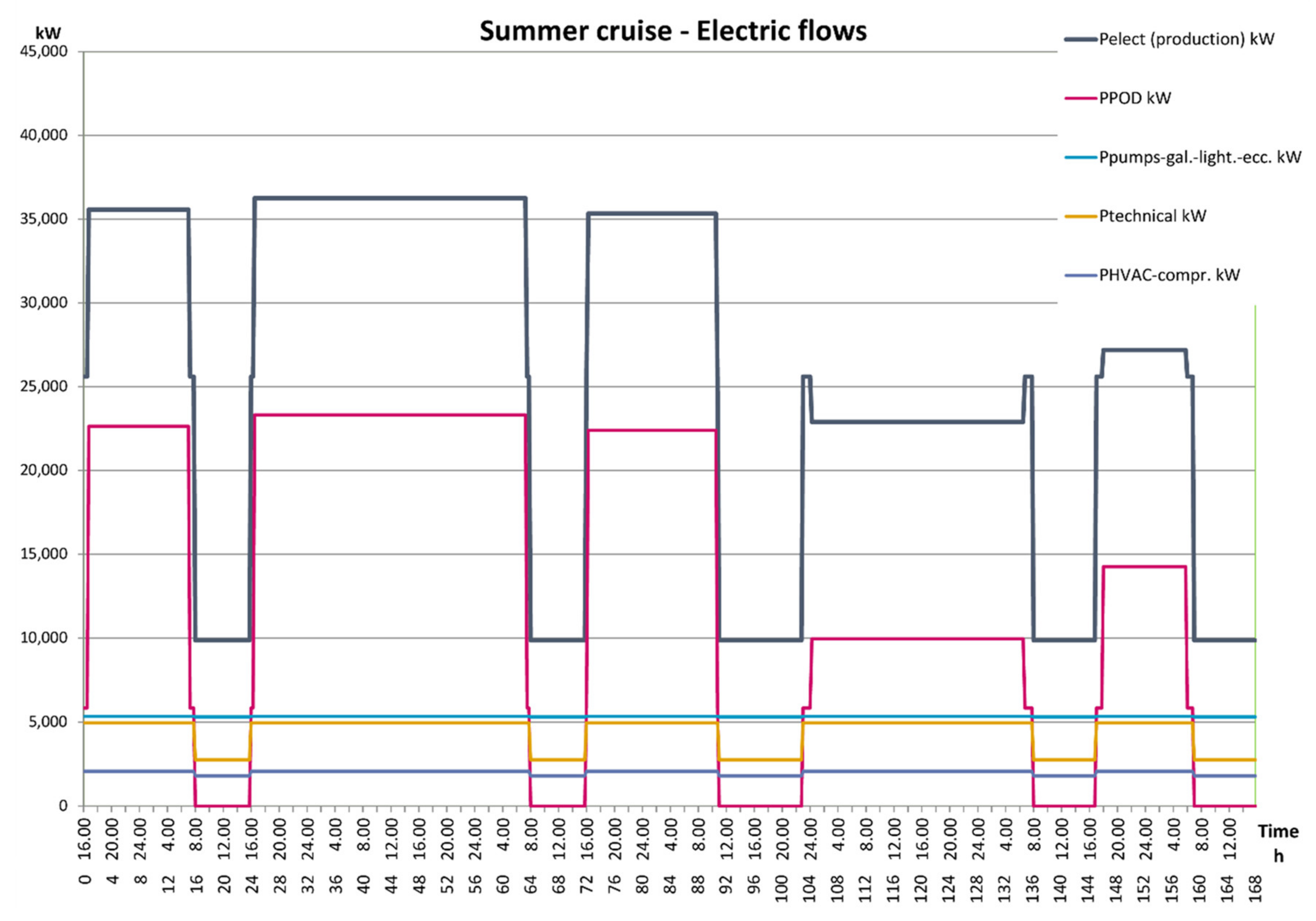
The electrical demand (Pelect) is the sum of the following contributions:
  • PPOD—power for the pod propulsion system and for the maneuvering propellers;
  • P technical—absorbed power for non-propulsive technical uses;
  • P pumps—galley—lights, power absorbed for the hotel functions and for the relative systems, excluding that for air conditioning (HVAC);
  • P HVAC, absorbed power for air conditioning (during the summer cruise only);
The P HVAC is the required cooling capacity to be satisfied by absorption and compression refrigeration machines. The demand curves are shown in the diagrams of Figure 1 and Figure 2 respectively for winter and summer cruise.
Currently, on cruise ships most of the thermal users are satisfied first of all by the thermal carrier consisting of saturated steam at 10 bar and 180 °C, produced by thermal recovery on the exhaust gases of the engines and by integration boilers powered by liquid fuel. In addition, the heat recovered from the Hight Temperature (HT) cooling circuit of the ICEs (approx. 90 °C) can be partially used, while the heat of the Low Temperature (LT) cooling circuit (approx. 50 °C) remains unused and has to be dissipated. To achieve an optimal exploitation of the heat recovered from the engines, the production of mechanical energy by means of bottom cycles, fed by the highest temperature heat source, must be considered as a priority. It is, therefore, recommended to use as much high temperature heat as possible for the mechanical energy production, feeding the different thermal users at a temperature level close (slightly higher) to the temperature of the user itself.
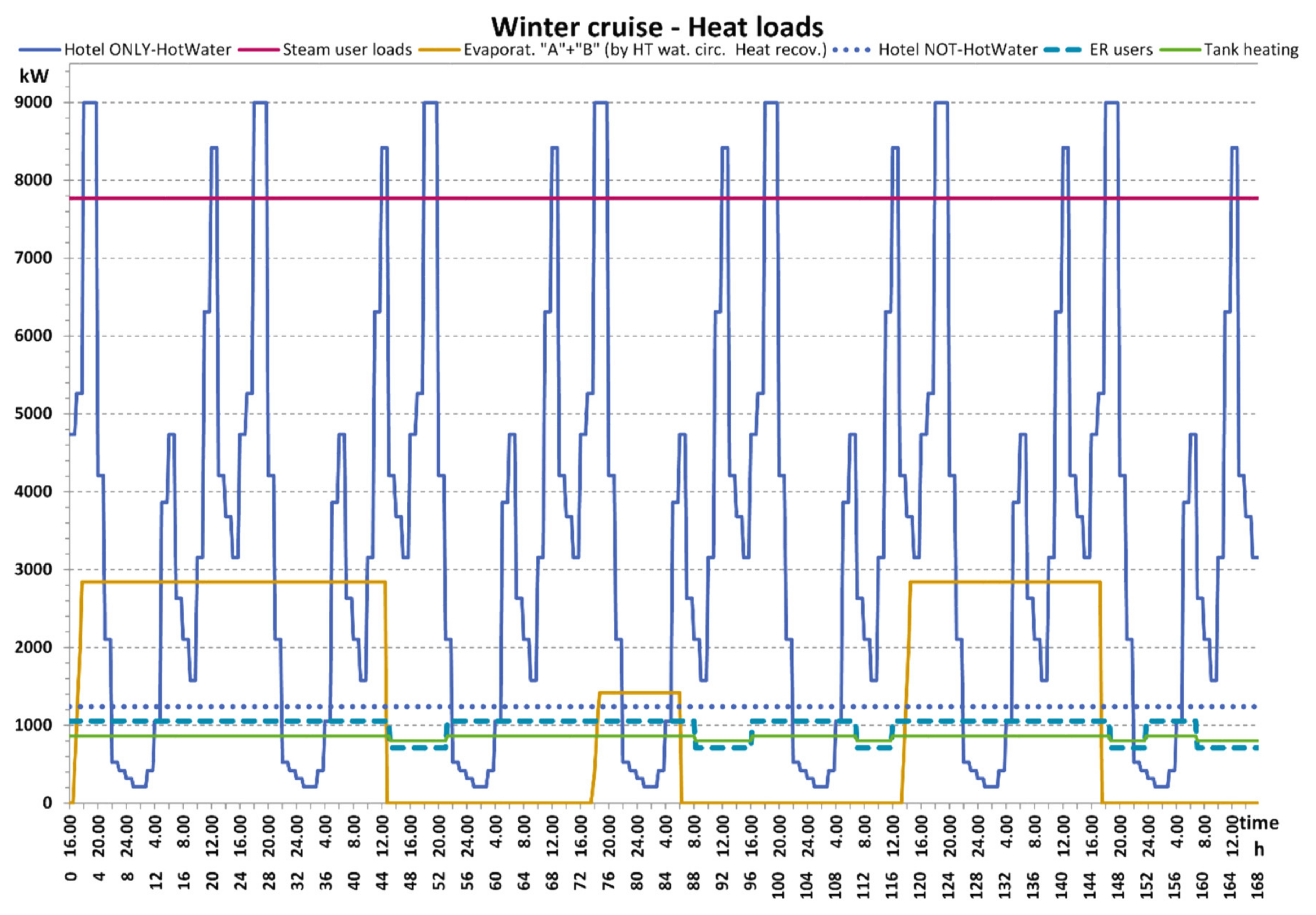
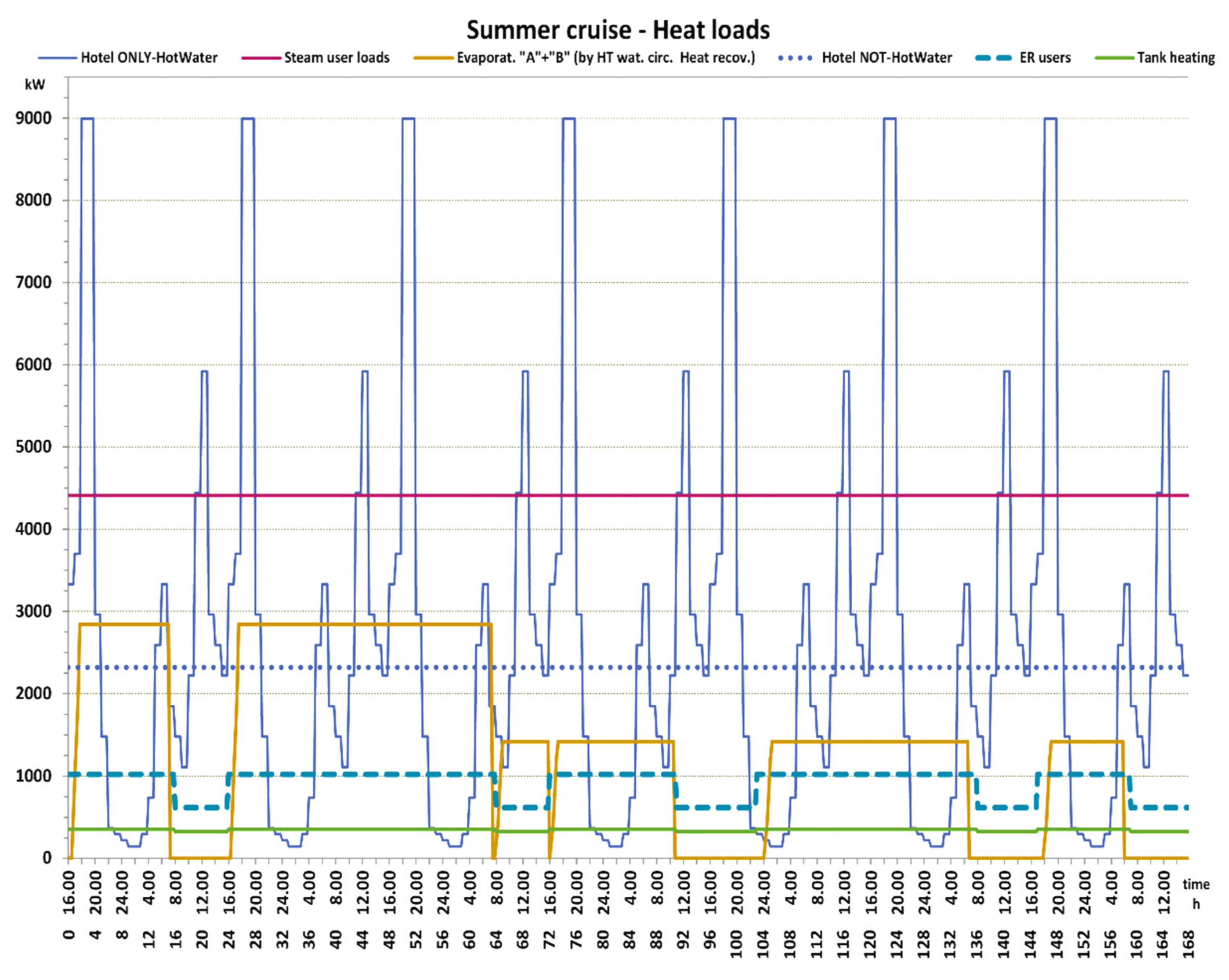
The following users are mandatory satisfied by the steam vector (“steam user loads” in Figure 3 and Figure 4):
  • Thermal request for air conditioning heating;
  • Thermal request for galley users, excluding the galley hot water use;
  • Laundry steam. The other on-board thermal users have been grouped into the following terms (Figure 3 and Figure 4):
  • Hotel only—hot water, for sanitary use, at about 60 °C;
  • Hotel not hot water, at about 90 °C (swimming pool heaters and laundry);
  • ER users (thermal consumption in the engine rooms) at about 90 °C;
  • Tank heating (thermal treatment of fuel, sludge, etc.) at about 50 °C;
  • Evaporat. “A” + ”B” (thermal consumption of the evaporation desalinators for producing pure water to be used in engines type “A” and “B”).
In the optimization procedure, the input data of the electrical and thermal hourly requests will be organized in the following matrices (day of the cruise—time of day):
  • Electric power, RICEL,
  • Heat as saturated steam at 10 bar and 180 °C, RICTER_St,
  • Hot water at 60–90 °C, RICTER_HTW,
  • Chilled water at 8 °C, RICOOL.
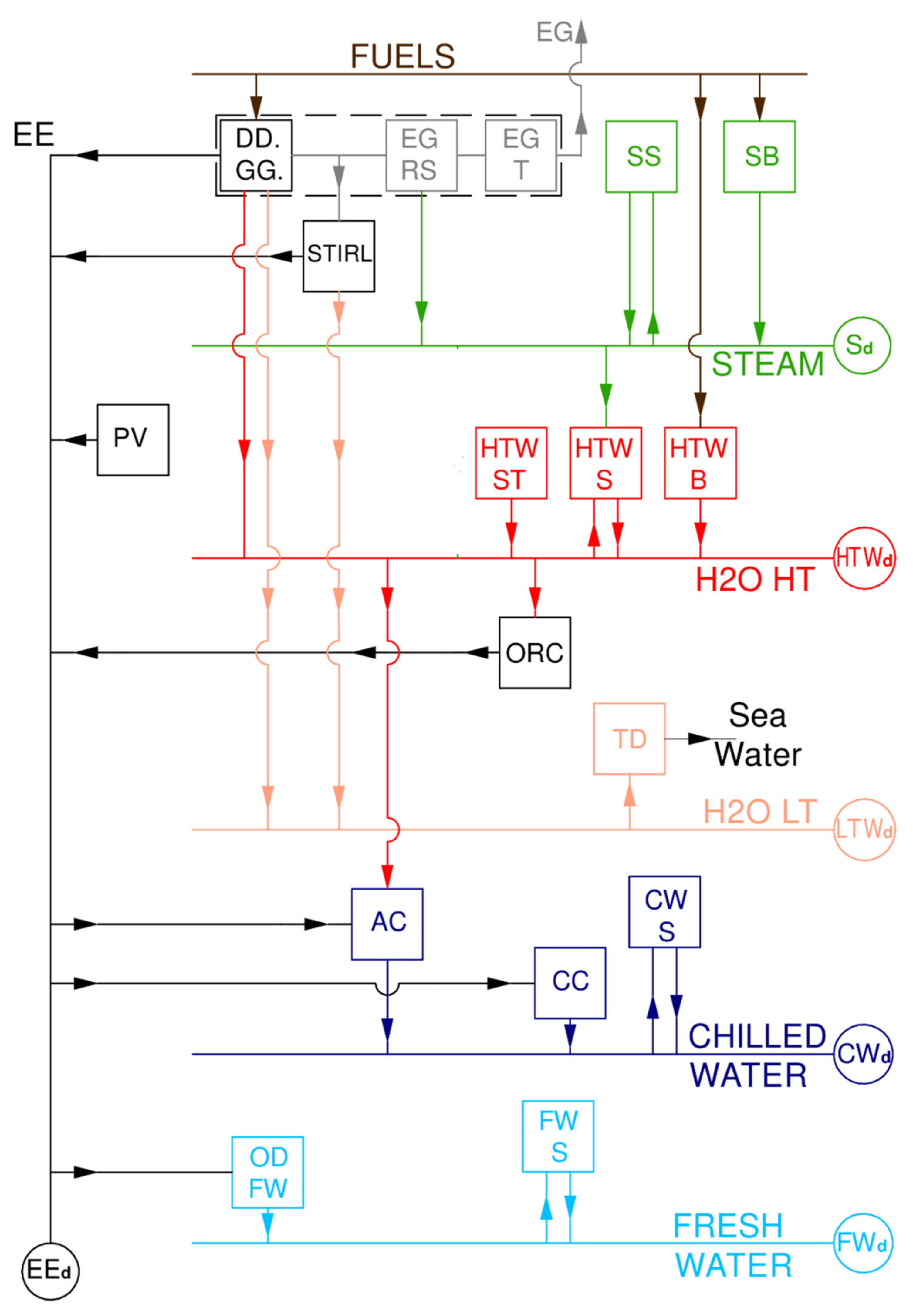
The last three matrices correspond to the thermal energy carriers STEAM, H2O HT and H2O LT in Figure 5. The thermal demands classified as low temperature (40–45 °C) are considered to be certainly satisfied by the low temperature hot water produced by the ICE, without the need for integrations.

2.2. Model Super-Structure

To allow optimal exploitation of fuel energy, various components dedicated to energy recovery from the main engines can be considered, such as ORC and Stirling bottom units, thermal storage systems, absorption refrigeration chillers, etc.
Once the super-structure of the energy system has been defined including all possible components, the optimization process will have to identify which components will be actually installed and the time scheduling of the load of each of them.
The whole super-structure is schematized in Figure 5, where each component is represented as a box, connected to the other components of the system and to the end users by means of the flows that will appear in the MILP model.
The seven energy vectors connecting the system with the users, highlighted in Figure 5, are the following:
  • Exhaust gases (EG), which directly feed the Stirling engine and the recovery boilers (EGRS), without any connection with other on-board users.
  • Electric power (EE) for propulsion, hotel services and all auxiliaries of the on-board energy system; it must meet the electrical energy demand (EEd).
  • Steam (STEAM); it must meet the steam demand (Sd).
  • Hot water at 85–90 °C (H2O HT); it must meet the hot water demand (HTWd).
  • Hot water at about 50 °C (H2O LT); it must meet the low temperature water demand (LTWd), or must be dissipated.
  • Chilled water at 8–10 °C (CHILLED WATER); it must meet the for chilled water demand (CWd).
  • Fresh water; it must meet the demand for fresh water (FWd); the latter is considered constant for simplicity, regardless of the ship’s operating conditions, and its effect on the whole energy consumption of the ship is limited to the electric energy demand of the reverse osmosis desalinator.
The components possibly adopted inside the on board energy system, shown in Figure 5, are the following:
  • DD. GG. Main diesel engines. This block is modeled considering the actual individual ICE, allowing the definition of the optimal management of the engines within the solution of the overall system optimization problem. In the case study the block is made up of 5 ICE—2 units of 14,400 kWmecc/600 rpm each (12V) and 3 units of 9600 kWmecc/600 rpm (8L) [53]. This block contains also the required auxiliaries for the engine operation, such as the exhaust gas recovery system (EGRS) and the exhaust gas treatment unit (exhaust gas treatment—EGT).
  • Stirl. Stirling units directly powered by the exhaust gases engine [54].
  • SB. Steam Boiler. It integrates the heat recovery from the ICE if necessary.
  • SS. Steam storage.
  • HTW. Boilers, identified accordingly to 3 different types of feeding energy considered—liquid fuel (B), steam taken from the on-board steam carrier (S) and thermal solar panels (ST). The HTW S boilers also possibly has a thermal storage function, at a temperature of 90 °C.
  • ORC. Organic Rankine cycle units for the electrical conversion of the heat recovered by the engines.
  • TD. Thermal dissipater. It has to dissipate the excess thermal power in the H2O LT line into the seawater.
  • AC. Absorption chillers. They can be powered by H2O HT line and, indirectly, also by way of the steam line.
  • CC. Compression chillers traditionally present on board the ship, whose size is determined in relation with the introduction of the absorption chillers.
  • CWS. Chilled water storage.
  • ODFW. Reverse osmosis desalinator.
  • FWS. Fresh water storage.
  • PV. Photovoltaic solar panels, the overall surface of which is optimized.

2.3. Linearized Model of the Components

As mentioned before, to reduce the computational effort in optimizing the on-board energy system during the whole cruise, linearized models have been used for all the components potentially present in the super-structure.
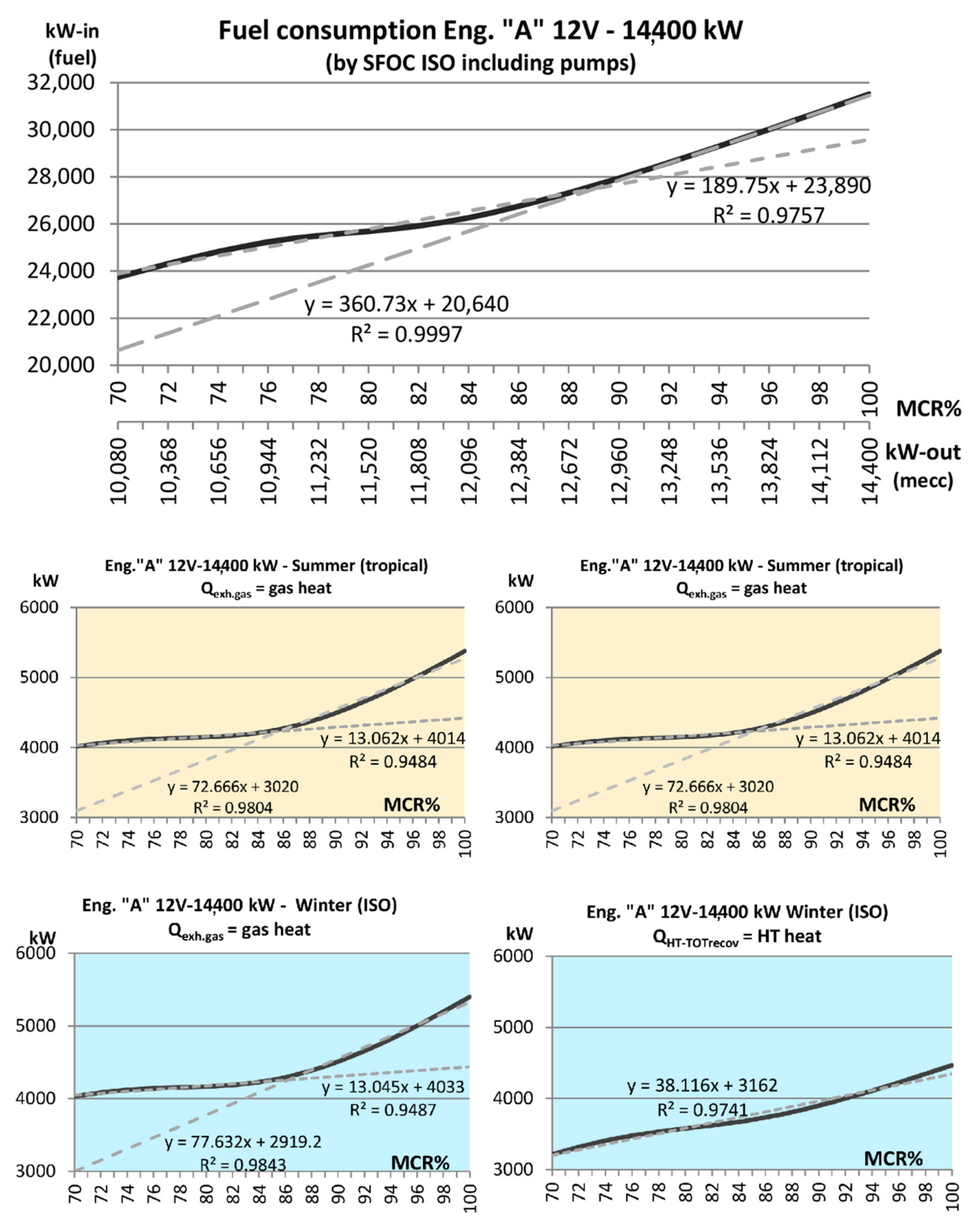
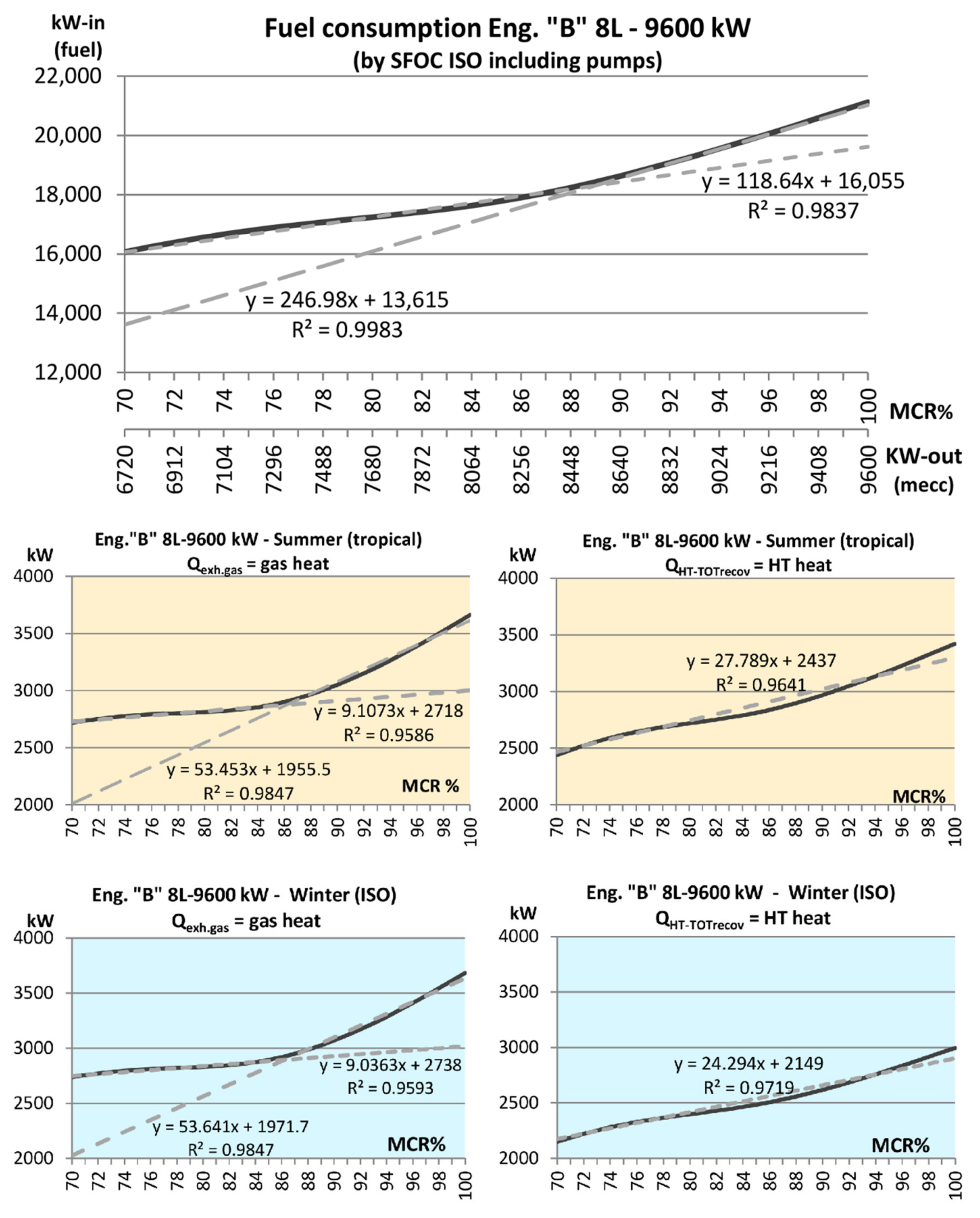
In particular, the linearized models of the 12 V and 8 L Diesel engines are obtained directly from the operating curves provided by ship manufacturer [53]. To evaluate the enthalpy content, which can be extracted from the gases, a minimum temperature of 170 °C has been considered. The characteristic curves of the ICE are shown in Figure 6 and Figure 7, together with the linearization equations. They show the fuel consumption, the thermal power recovered by the exhaust gases (Qexh.gas) and the thermal power recovered by the H2O HT line (QHT-TOTrecov), as a function of the engine load (MCR%).
For each ICE, the variables describing the load of in the linearized models are shown below. They include binary variables that describe the ON/OFF status of each group:
  • MCR1(g,i,j), % of the load in the low-load part of the operating curve (Figure 6 and Figure 7);
  • MCR2(g,i,j), % of the load in the high-load part of the operating curve (Figure 6 and Figure 7);
  • y1(g,i,j), ON/OFF in the low-load part of the operating curve (Figure 6 and Figure 7);
  • y2(g,i,j), ON/OFF in the high-load part of the operating curve (Figure 6 and Figure 7);
where g, i and j are generic day, hour and ICE, respectively. The constraints affecting ICE operation are:
y1 (g,i,j) × MCRinf ≤ MCR1 (g,i,j) ≤ y1 (g,i,j) × MCRm
y2 (g,i,j) × MCRm ≤ MCR2 (g,i,j) ≤ y2 (g,i,j) × MCRsup
y1 (g,i,j) + y2 (g,i,j) ≤ 1
The constraints expressed by Equations (1) and (2), allow the choice variables MCR1 and MCR2 to take positive values only if the j-th motor is ON in the i-th hour of the g-th day and the engine load is within the permitted operating ranges. The last constraint (Equation (3)) states that only one of the two choice variables MCR1 and MCR2 can actually be non-zero. The actual load—MCR (g, i, j)—and the electrical power produced by each motor—Pel (g, i, j)—can therefore be calculated as:
MCR (g,i,j) = MCR1 (g,i,j) + MCR2 (g,i,j)
Pel (g,i,j) = MCR (g,i,j)/100 × Pmax (j) × eta_el
Engine fuel consumption (fuel) is obtained from the linearized characteristic curves in a similar way to Equations (1)–(5) and are calculated using the following Equations (6)–(8), where it is necessary to specify a pair of coefficients (A, B) for each linearization part:
Fuel1 (g,i,j) = A1 (j) × (MCR1 (g,i,j) – MCRinf × y1 (g,i, j)) + B1 (j) × y1 (g,i,j)
Fuel2 (g,i,j) = A2 (j) × (MCR2 (g,i,j) – MCRinf × y2 (g,i,j)) + B2 (j) × y2 (g,i,j)
Fuel (g,i,j) = Fuel1 (g,i,j) + Fuel2 (g,i,j)
The power produced and the thermal flows consumed at the different loads by the ORC groups have been modeled on the basis of the data available for the Climeon group [55]. They show an efficiency dependent on the temperatures of the supply thermal vector and of the cooling flow, therefore the efficiency can be regarded as constant if the group is fed by the hot water line at 85–90°C (H2O HT), and the cooling flow is sea water, which temperature depends only by the winter/summer conditions.
The model considers one or more ORC groups, all of the same nominal size (150 kW), powered by the recovery circuit on high temperature with a constant flow rate of 40 L/s. Each ORC group may operate at nominal load, with constant electrical efficiency, if the hot water at 90 °C is not completely consumed by the other users, otherwise, the ORC groups remain in stand-by. The electrical efficiency is set consistently with the technical data supplied by CLIMEON group [55]:
  • eta_orc = 7% in the summer cruise, considering an average cooling temperature of 30 °C,
  • eta_orc = 10% in the winter cruise, considering an average cooling temperature of 15 °C.
The variables describing the operation of the Stirling and ORC groups in the linear model are the following, where g, i and j are generic day, hour and Stirling/ORC, respectively:
  • Pel_str (g,i,j), electrical power produced by each Stirling [kW];
  • y_str (g,i,j), ON/OFF condition of each Stirling;
  • X_str (j), existence of each Stirling;
  • Pel_orc (g,i,j), electrical power produced by each ORC [kW];
  • y_orc (g,i,j), ON/OFF condition of each ORC;
  • X_orc (j), existence of each ORC.
A group of three constraints similar to Equations (1)–(3), allows to determine the heat recovered from the ICE gases (Hexg) and destined for the production of steam or for feeding the Stirling, while a single linear relationship is sufficient to express the heat recovered (HTh), by the HTW vector, vs the load of each ICE, given its intrinsically close to a linear trend (Figure 6 and Figure 7):
Hexg1 (g,i,j) = C1 (j) × (MCR1 (g,i,j) – MCRinf × y1 (g,i,j)) + D1 (j) × y1 (g,i,j)
Hexg2 (g,i,j) = C2 (j) × (MCR2 (g,i,j) – MCRinf × y2 (g,i, j)) + D2 (j) × y2 (g,i,j)
Hexg (g,i,j) = Hexg1 (g,i, j) + Hexg2 (g,i,j)
HTh (g,i, j) = E(j)×MCR (g,i,j) + F(j) × (y1 (g,i,j) + y2 (g,i,j))
As described above, the Stirling and ORC groups are considered to operate at a constant power value, close to the nominal one, therefore, the optimizer is called to define the optimal number of modules that will come into operation at any hour, thus operating with a “step” modality.
The thermal input of the Stirling modules is considered directly derived by the exhaust gases line, without passing through the production of steam or hot water. For this reason, the energy exploitation by the Stirling groups is considered to result in a lower reduction in the availability of steam, compared to the exploitation by the users who actually use the steam. For this reason, the consumption of the Stirling groups (Hexg_str) appears multiplied by a coefficient equal to 0.9 in the subsequent thermal balance of the steam vector (Equation (39)). The thermal input of the ORC modules (HTh_orc) is considered instead to directly derive by the HTW line, at about 90 °C. The electric power produced by each Stirling group (Pel_str) and by each ORC group (Pel_orc) in each hour of the cruise, is then obtained from the following relations:
Hexg_str (g,i, j) = Pel_str (g,i, j)/eta_str
y_str (g,i, j) × Pel_strinf ≤ Pel_str(g,i, j) ≤ y_str (g,i, j) × Pel-strsup
HTh_orc(g,i, j) = Pel_orc (g,i, j)/eta_orc
y_orc (g,i, j) × Pel_orcinf ≤ Pel_orc (g,i, j) ≤ y_orc (g,i, j) × Pel-orcsup
In the following the numerical values of the efficiencies and of the COP regarded as constant, are reported for all the remaining components considered in the super-structure:
  • SB. Steam generator. It produces the integration heat when the heat recovery from the ICE is not enough. In the linearized model, a constant efficiency of approx. 70% is considered, accordingly to the average value indicated by the ship manufacturer [53].
  • SS. Steam storage. Its possible presence and dimensions will be optimized according to the thermal requirements and the overall constraints of the system. Keeping in mind that all the storage will be characterized by a short operating cycle (few hours) the losses due to dispersion have been neglected, as an acceptable approximation.
  • HTW. Boilers, divided according to 3 different types of input power considered: liquid fuel (B), on board steam (S) and solar thermal panels (ST). For the latter, it will be necessary to carefully check the definition of a penalty function relating to the dimensions associated with a system of this type. A constant efficiency of 70% for HTW B and 90% for HTW S will be used in the model, accordingly to the indications by the shipbuilder [53], while for the thermal solar panels, the data of a typical vacuum tube collector, like Sunwood SW15 by Sunwood energy solutions (viale del lavoro 18, 37067 Villafranca di Verona, VR, Italy) have been used, for which the optical efficiency and the heat transmission coefficients a1 and a2 are known (Table 1).
  • The HTW S has also a thermal storage function, for users at temperature lower than 90 °C. In addition, for this component, heat loss has been neglected as an acceptable approximation.
  • TD. Thermal dissipater. It has to dissipate the excess thermal power in the H2O LT line into the seawater. The auxiliary consumptions of the TD are accounted for in the non-propulsive electrical loads, according to the operating data collected for the reference ship. Therefore, the model of this component is not explicitly considered in the balance of energy flows.
  • AC. Absorption chiller. They can be powered by the H2O HT network and, indirectly, by the steam network, too. The linearized model of the absorption chiller calculates the thermal consumption and the cooling power produced at different loads, following the performance of a typical water-lithium bromide absorption machine, presented by Joudi and Lafta, in [57]. Their simulations show that the COP remains approximatively constant, if the activation temperature is in the range 85–95 °C. Considering to fed the machine with the hot water carrier at 85–90 °C (H2O HT) a constant prudential value of the COP = 0.6 has been assumed.
  • CC. Compression chillers. They are traditionally present on board the ship, whose size will be reduced in relation to the introduction of the absorption chillers. Referring to the data available from the manufacturers [58], a COP = 5.0 has been adopted.
  • CWS. Chilled water storage. Considering that all the on board storages are characterized by a short operating cycle (a few hours) the losses due to heat dispersion will be considered null, simply taking into account the maximum accumulated volume.
  • ODFW. Reverse osmosis desalinator. The linearized model of the electrical consumption and of the fresh water flow produced refers to the components currently installed on board the ship, whose productivity and electrical consumption are known [53].
  • FWS. Fresh water storage. Given that the accumulation of fresh water is currently present on board, its auxiliary consumption is accounted for in the non-propulsive electrical loads. Therefore, the model of this component will not be explicitly considered in the super-structure.
The cooling flows produced by the absorption and compression chillers are expressed by the following variables:
  • Cool_abs (g,i), cooling power produced by the absorption chillers [kW];
  • Cool_com (g,i), cooling power produced by the compression chillers [kW].
Relations 17–20, similar to Equations (13)–(16), relate the cooling powers produced by the chillers to the energy vectors consumed, i.e., the thermal power HTh_abs (g,i), derived from the HTW line, and the electric power Pel_com (g,i), respectively.
HTh_abs (g,i) = Cool_abs (g,i)/COP_abs
Pel_com (g,i) = Cool_com (g,i)/COP_com
Cool_abs (g,i) ≤ Cool_abs_max
Cool_com (g,i) ≤ Cool_com_max
Cool_abs_size ≥ Cool_abs (g,i)
Cool_com_size ≥ Cool_com (g,i)
The last two equations allow us to identify the minimum size of the two types of chillers that are capable of producing the required cooling powers at any time of the day, according to the optimal management. The size of the absorption chillers allows their penalty function to be identified and used during the optimization of the objective function.
The integrative thermal powers produced by the steam and the water boilers (Int_St (g,i), Int_HTW (g,i)) and the related fuel consumption (Fuel_BSt (g,i) and Fuel_BHt (g,i)), are expressed by the following equations:
Fuel_BSt (g,i) = Int_St (g,i)/eta_St
Fuel_BHt (g,i) = Int_HTW (g,i)/eta_HTW
Int_St (g,i) ≤ Int_St_max
Int_HTW (g,i) ≤ Int_HTW_max
The variables describing the state of two thermal storages (steam and water HTW) are the thermal input and output powers, the quantity of energy stored and the binary variables that indicate the incoming or out coming flow condition from each storage:
  • Lev_St (g,i), energy stored in the steam storage [kWh];
  • Input_St (g,i), input power in the steam storage [kW];
  • Output_St (g,i), output power in the steam storage [kW];
  • Lev_HTW (g,i), energy stored in HTW storage [kWh];
  • Input_HTW (g,i), power input into the HTW storage [kW];
  • Output_HTW (g,i), output power in the HTW storage [kW];
  • y_Input_St (g,i), ON/OFF of the flow entering the steam storage;
  • y_Output_St (g,i), ON/OFF of the output stream in the steam storage;
  • y_Input_HTW (g,i), ON/OFF of the flow entering the HTW storage;
  • y_Output_HTW (g,i), ON/OFF of the output stream in the HTW storage.
The storage energy balance in the generic operating hour calculates the level of energy stored as the level of the previous hour, increased by the net input during the current hour. It is necessary to ensure the continuity of the levels of energy stored during the passage from one cruise day to the next. In correspondence with the first hour of each day, it is therefore, necessary to consider the conditions of the last hour of the previous day. To do this, the following IF cycle has been introduced:
if (g = 1 and I = 1) then
Lev_St (1,1) = Lev_St (7,24) − Output_St (1,1) + Input_St (1,1)
elif (g > 1 and i = 1) then
Lev_St (g,i) = Lev_St (g-1,24) − Output_St (g,1) + Input_St (g,1)
else
Lev_St (g,i) = Lev_St (g,i-1) − Output_St(g,i) + Input_St (g,i)
end-if
The description of the steam storage potentially present inside the MILP model has to be completed by a group of constraints that allow one phase only (charge or discharge) to be active in each hour, with a power limited by a maximum value, previously defined.
It is, therefore, necessary to introduce binary variables that indicate whether, in each hour, a storage charging or discharging phase is taking place; these variables allow a constraint to be introduced, which excludes at least one of the two phases, preventing the solver from potentially evaluating infinite pairs of input and output values to achieve a certain variation of the stored energy. The optimal size of the storage will result as the upper limit of the energy levels accumulated during the cruise, while the choice of not using it will be highlighted by a null value of this upper limit.
Input_St (g,i) ≤ Input_St_Max × y_Input_St (g,i)
Output_St (g,i) ≤ Output_St_Max × y_Output_St (g,i)
y_Input_St (g,i) + y_Output_St(g,i) ≤ 1
Lev_St_size ≥ Lev_St (g,i)
The energy levels of the thermal storage at the beginning and at the end of the cruise are the same and they are chosen by the optimization algorithm.
A completely similar group of relations describes the accumulation of HTW hot water. Additional model optimization variables are:
  • SttoHTW (g,i), thermal power transferred from the steam to the HTW line [kW];
  • Apv, Ast, solar photovoltaic panels and thermal collector surfaces [m2].
For photovoltaic panels and solar collectors, the expected production is considered, hour by hour, on the basis of an average insolation values of a typical day, for a European cruise area. Taking into account the variability of the ship’s route, a horizontal orientation of the panel has been considered. The data on the expected production in [W/m2] of photovoltaic panels and solar collectors are contained in row vectors of 24 elements, called respectively GNpv (i) and GNst (i). A constant coefficient takes into account the expected electrical losses in the interconnection circuits and inverters of the photovoltaic system (BOS = 0.80). Therefore, the linearized model of the solar components is reduced to the following block of equations:
Ppv (g,i) = BOS × GNpv (i) × Apv/1000
Pst(g,i) = GNst(i) × Ast/1000
Apv ≤ ApvMax
Ast ≤ AstMax
Finally, for both the components necessarily present (cogeneration engines and boilers) and the potentially present ones (ORC and Stirling groups, thermal storage, absorption chillers, photovoltaic panels and thermal collectors) a group of constraints on the binary variables of existence and on/off status of each component is introduced, to ensure that only existing components can be put in operation.

2.4. Energy Balances and Objective Functions

On the basis of the documentation made available by the manufacturer [53], the electrical and thermal demand curves have been identified for the two type of cruises (summer and winter).
The MILP model calculates, for each hour of the cruise, the balances of the nodes where the energy vectors produced by the system have to satisfy the user demands (Equations (38)–(41)): the electric demand (RICEL), the steam demand (RICTER_St), the hot water demand (RICTER_HTW) and the chilled water demand (RICCOOL).
j = 1 N I C E p e l g , i , j   +   j = 1 N s t r p e l _ s t r g , i , j   +   j = 1 N o r c p e l _ o r c ( g , i , j )   +   Ppv ( g , i )   - pel _ com   ( g , i )     RICEL   ( g , i )
j = 1 N I C E H e x g ( g , i , j ) + Int _ St ( g , i )   +   Output _ St   ( g , i ) - Input _ St   ( g , i ) - SttoHTW   ( g , i )     0.9 × j = 1 N s t r H e x g _ s t r g , i , j     RICTER _ St   ( g , i )
j = 1 N I C E H T h ( g , i , j )   +   Int _ HTW   ( g , i )   +   SttoHTW   ( g , i )   +   Output _ HTW   ( g , i )     Input _ HTW   ( g , i )     HTh _ abs ( g , i )     j = 1 N o r c H T h _ o r c g , i , j   +   Pst   ( g , i )     RICTER _ HTW   ( g , i )
Cool_abs (g,i) + Cool_com (g,i) + Output_CW(g,i) − Input_CW (g,i) ≥ RICCOOL (g,i)
Stirling engines are powered directly by the ICE flue gases, but are considered within the steam carrier balance, by introducing an appropriate reduction coefficient of consumption (0.90), which takes into account the direct transfer of thermal energy, without requiring the intervention of recovery boilers (EGRS).
As previously mentioned, the thermal demands classified as low temperature (40–45 °C) are considered to be certainly satisfied by the low temperature hot water produced by the ICE, without the need for integrations, so that the H2O LT balance is not considered in the optimization procedure.
In this paper, the MILP problem is solved by means of a multi-objective optimization, considering to minimize fuel consumption during the cruise and, at the same time, the size of the additional energy recovery system. This second objective is quantified by the PENALTY function which assigns 1 pt of penalty equivalent to approximately 10 m3 of additional volume occupied.
For thermal storage, absorption chillers, photovoltaic panels and solar collectors, penalties proportional to the optimized size are introduced.
A general objective function (OBJFunc) is also defined for the MILP problem, consisting of the weighted sum of the fuel consumption during the cruise, and of the PENALTY function.
Fuel _ TOT = g = 1 ,   i = 1 j = 1 N I C E F u e l ( g , i , j )   +   Fuel _ BSt ( g , i )   +   Fuel _ BHt ( g , i )
PENALTY = j = 1 N o r c P E N _ o r c ( j ) × X _ o r c ( j ) + j = 1 N s t r P E N _ s t r j × X s t r j +   Apv   ×   PENpv   +   Ast   ×   PENst +   Cool _ abs _ size   ×   PENabs   +   Lev _ St _ size   ×   PEN _ St + Lev _ HTW _ size   ×   PEN _ HTW
OBJFun = Fuel_TOT + PENALTY × PENconv
The PENconv conversion factor has the purpose of making the two terms of the objective function homogeneous [kWh] and to allow changing the relative importance of one objective with respect to the other.
Note that, in the perspective of multi-objective optimization, a specific value of the PENconv conversion factor simply identifies a point on the Pareto front, so that the possibility offered by the evolutionary approach with the software modeFRONTIER® to obtain the complete front, regardless of the value of PENconv, makes a careful definition of this coefficient absolutely non-critical.

3. Bi-Level Multi-Object Optimization

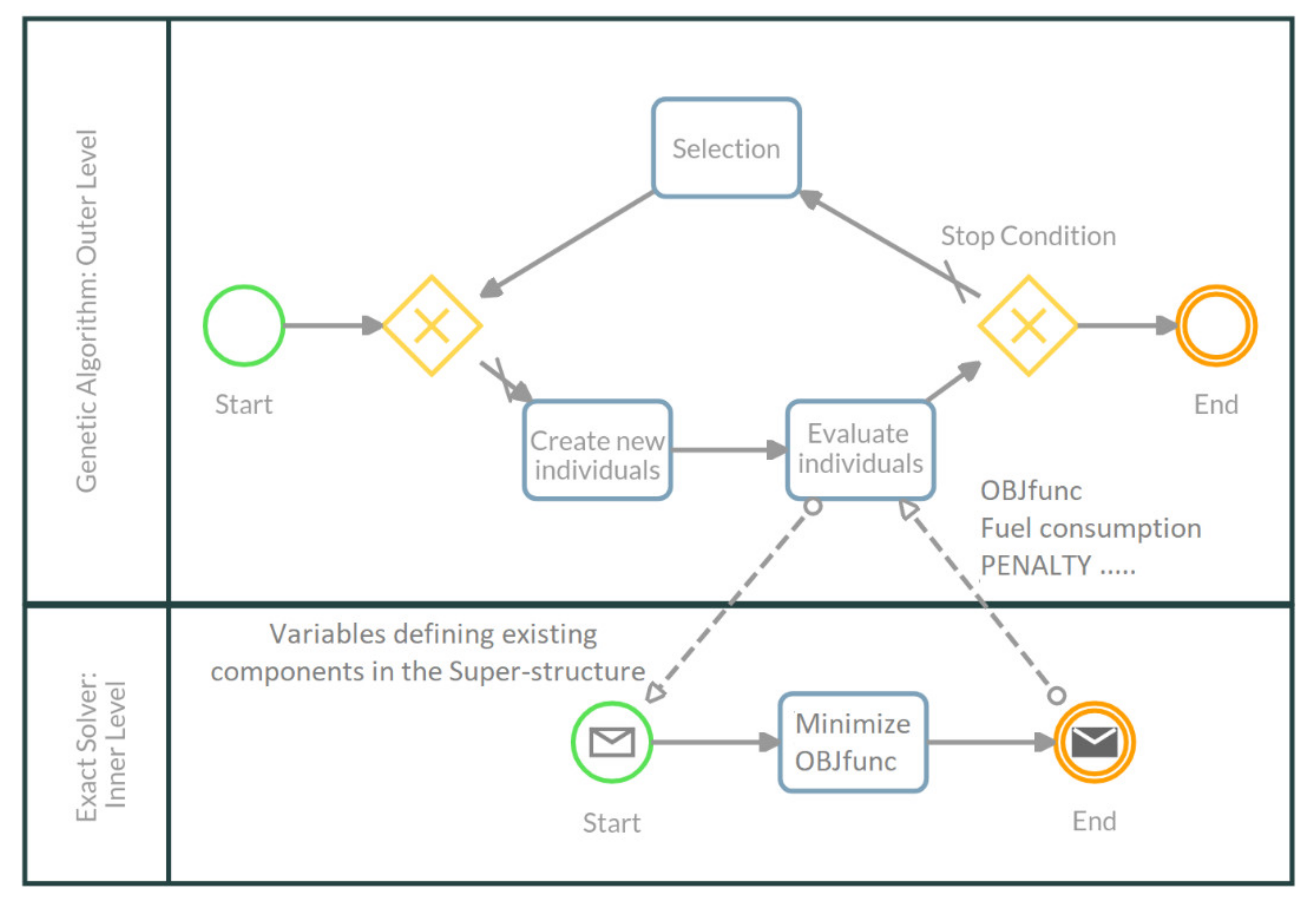
The bi-level optimization here introduced considers an external level, optimized with an evolutionary algorithm for the design choices, and an internal level optimized with a MILP solver for the choices on the optimal management of the components. A similar approach has been proposed by the authors for the optimization of ground-based cogeneration systems [52]. The bi-level procedure is based on an external genetic optimization algorithm, which creates a population of individuals, defined by genes that correspond to the optimization variables that determine the presence or absence of the different components in the super-structure (Figure 5). These values are assumed by the internal optimization level, based on the MILP procedure.
As well known, the latter is faster in solving management and resource allocation problems, if the number of choice variables that appear in multiple time intervals is lower. In fact, if the optimal solution in a certain time interval depends on that of many other intervals, the problem decomposition is less effective and the computational effort necessary to resolve the instance as a whole is considerably greater. The advantage of entrusting the choice of the optimization variables that determine the presence or absence of the different components to the external (genetic) level consists in subtracting these variables, which appear in all the time intervals of the cruise, from the optimization of the internal level. The choice variables managed by the external level are:
  • X_str (stirling), vector containing the binary variables expressing the presence/absence of each Stirling group;
  • X_orc (ORC), vector containing the binary variables expressing the presence/absence of each ORC group;
  • Apv, area occupied by photovoltaic solar panels [m2];
  • Ast, area occupied by solar thermal collectors [m2];
  • Cool_abs_size, absorption chiller size [kW];
  • Cool_com_size, compression chiller size [kW];
  • Lev_St_size, steam thermal storage size [kWh];
  • Lev_HTW_size, hot water thermal storage size [kWh].
These variables are generated at the external level (genetic algorithm: outer level in Figure 8) in a range previously defined by the designer and then acquired as constants by the MILP procedure that operates at the internal level (minimize OBJfunc module in the exact solver: inner level in Figure 8).
At the internal level, the optimal management of the components that are present in the considered individual is generated as the solution of the MILP problem. Therefore, the corresponding values of fuel consumption during the cruise and the overall penalty are obtained. In this way, the internal level performs a single-objective optimization, defined as a combination of the two objectives of reducing fuel consumption and limiting the total volume, which is then used by the external genetic algorithm, in the selection phase of the multi-objective optimization.
The external level selects the individuals to be used in the creation phase of the next generation, according to the criteria provided by the genetic algorithm. The new generation is therefore characterized by a different set of variables managed externally; the latter are then passed to the internal level and the iteration continues until the expected number of generations is completed.
The NSGA-II (non-dominated sorting genetic algorithm-II) genetic algorithm, widely used in literature [59], has been identified as a proper algorithm for the considered application. This approach allows multi-core processors to be used, running internally multiple sessions in parallel and significantly speeding up the optimization process. In this way, the definition of coupling variable [60] is not necessary, because the two levels (internal and external) can interact effectively within the modeFRONTIER® environment, without the need to explicitly define further constraints for the internal optimization, as is usual in the local-global optimization of models mainly described by continuous variables [61].
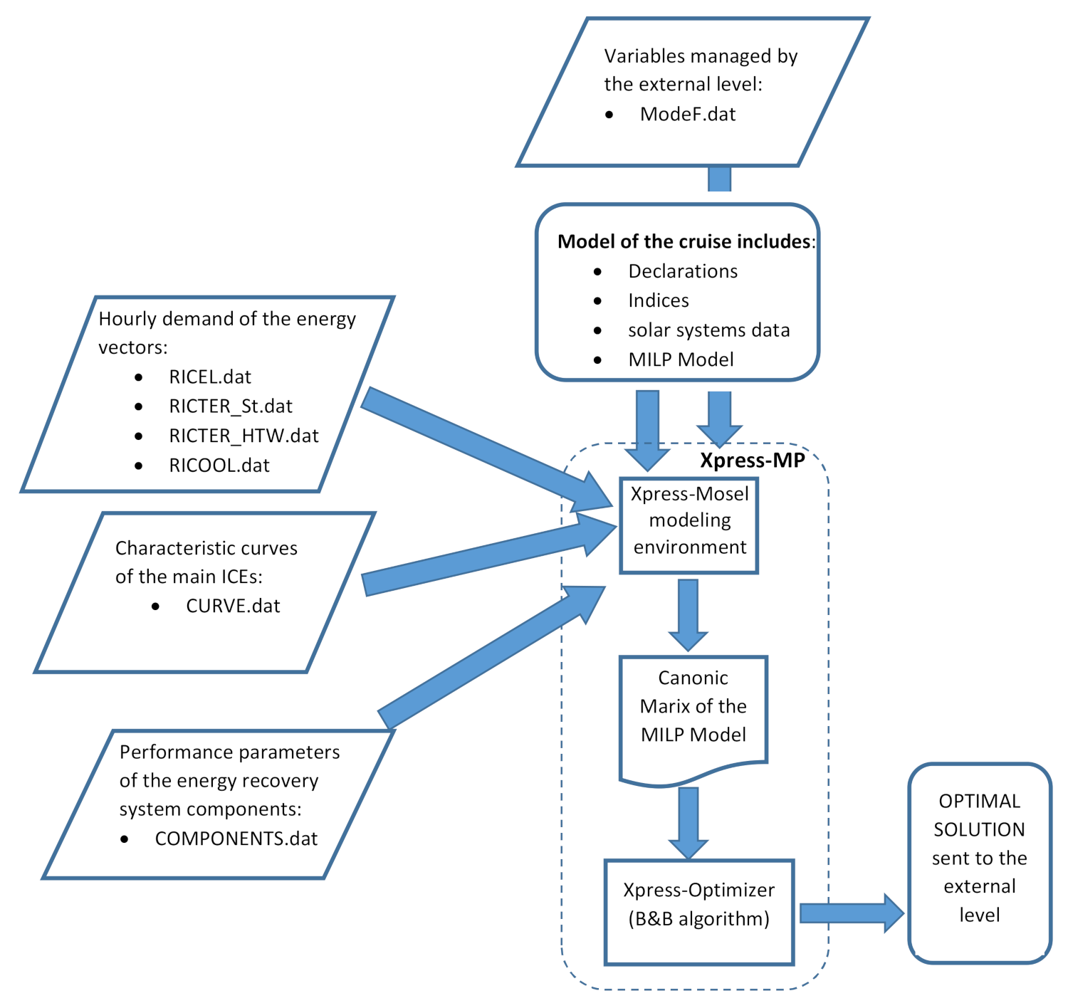
In the MILP procedure used in the internal level of the bi-level optimization, all the constraints regarding the existence, or the choice of the size, of the components are not active, as they are managed by the external level, making faster the definition of the optimal solution for a single individual. Figure 9 schematically represents the flow chart of the MILP procedure with the files that allow interaction with the external level.
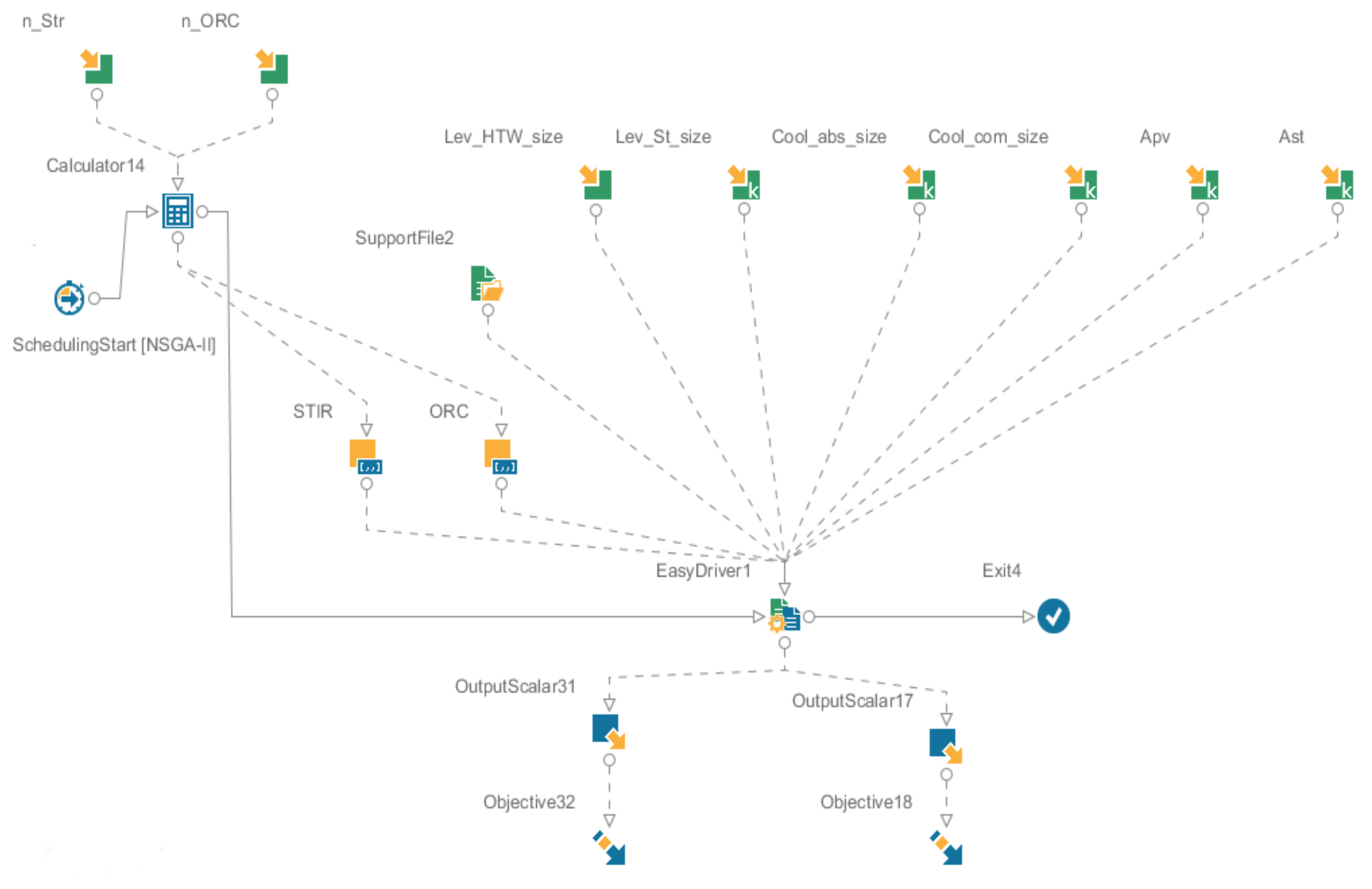
The modeFRONTIER® workflow shown in Figure 10 allows to define in a semigraphic way the multi-objective genetic optimizer. At the same time, the workflow window also constitutes the interface that allows the designer to change the ranges of the choice variables managed by the external level. Table 2 summarizes the functions of the graphical workflow nodes in Figure 10.

4. Results

Two separate optimizations have been carried out, using as reference a summer cruise and a winter cruise of the considered ship. These two cases differ for the total fuel consumption (about 11,000,000 kWh in summer and about 12,500,000 kWh in winter), for the sea temperature (which affects the condenser cooling of the ORC groups and therefore their electrical efficiency) and for the thermal and cooling demands of the ship. In particular, in the case study, the request for cooling capacity is considered constant and equal to 8000 kW in the summer case, and equal to zero in the winter case.

4.1. Preliminary Optimizations

Some preliminary optimizations of the overall instance have been performed by X-Press, using the ranges of the parameters and the penalty coefficients shown in Table 3, in order to identify the ranges of the choice variables to be considered in the multi-objective optimization. In this preliminary optimizations the objective function is the minimum value of OBJFun, Equation (44), for the summer cruise.
The preliminary results have been obtained by setting the gap at 1% of the current value of the objective function. They show that, with the penalty coefficients considered, neither the photovoltaic panels nor the solar thermal collectors are included in the optimal solution. The same happens if the penalties are reduced by 4 times, showing that, for the conditions considered, these components can be excluded. In particular, the solar thermal collectors do not appear in the optimal solution even by adopting these extremely low values of the corresponding penalty factor, indicating how their contribution to the production of thermal energy is actually nullified by the wide availability of heat on board and by the high value of efficiency of the integration boilers.
Table 4 shows some of the results obtained by optimizing the instance with Xpress, varying the maximum number of Stirling groups that can be present in the optimal solutions, the maximum number of ORC groups and the maximum value of the flow exchanged with the HTW storage.
One or more ORC groups and several Stirling groups are generally included in the optimal solution together with the absorption chillers, having a total installed cooling capacity of 8000 kW. Furthermore, with the adopted values of the penalty coefficients, the tension to carry out an important energy recovery by means of Stirling groups is much greater than the tension to introduce ORC groups. In Table 4, the optimizations which give the maximum allowed number of Stirling groups as optimal results are highlighted in yellow. The results reported in the second part of Table 4 show very limited variations in the total fuel consumption as the maximum allowed number of ORC groups increase.
This preliminary evaluation shows that no steam storage is installed, while the hot water storage reaches an overall value of about 5000 kWh of maximum energy content, evidently linked to the value used to limit the heat flow exchanged. In fact, by raising this limit (the third part of Table 4), the maximum energy content of the HTW storage also rises. It should be noted that the electrical production by the ORC also increases with the size and thermal flow of the HTW storage at 90 °C, highlighting how the latter also partially contributes to feeding of the ORC groups. These are in effect connected on the line of the HTW thermal vector, which can exchange heat also with the storage.
Taking into account these preliminary results, the ranges for the optimization variables managed by the external level reported below in Table 5 have been considered.

4.2. Pareto Front of the Bi-Level Optimization

On the basis of the preliminary optimization, the bi-level optimization was carried out according to the procedures presented in Chapter 3. The multi-objective optimization carried out with modeFRONTIER® allowed to identify the Pareto front for the two cases examined (winter and summer cruise).
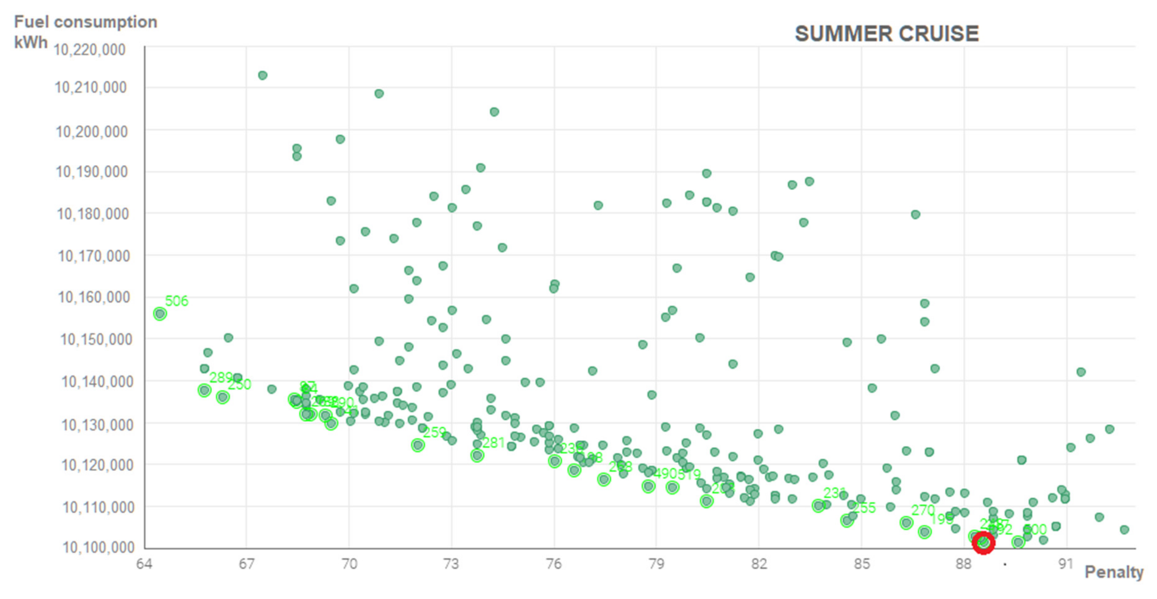
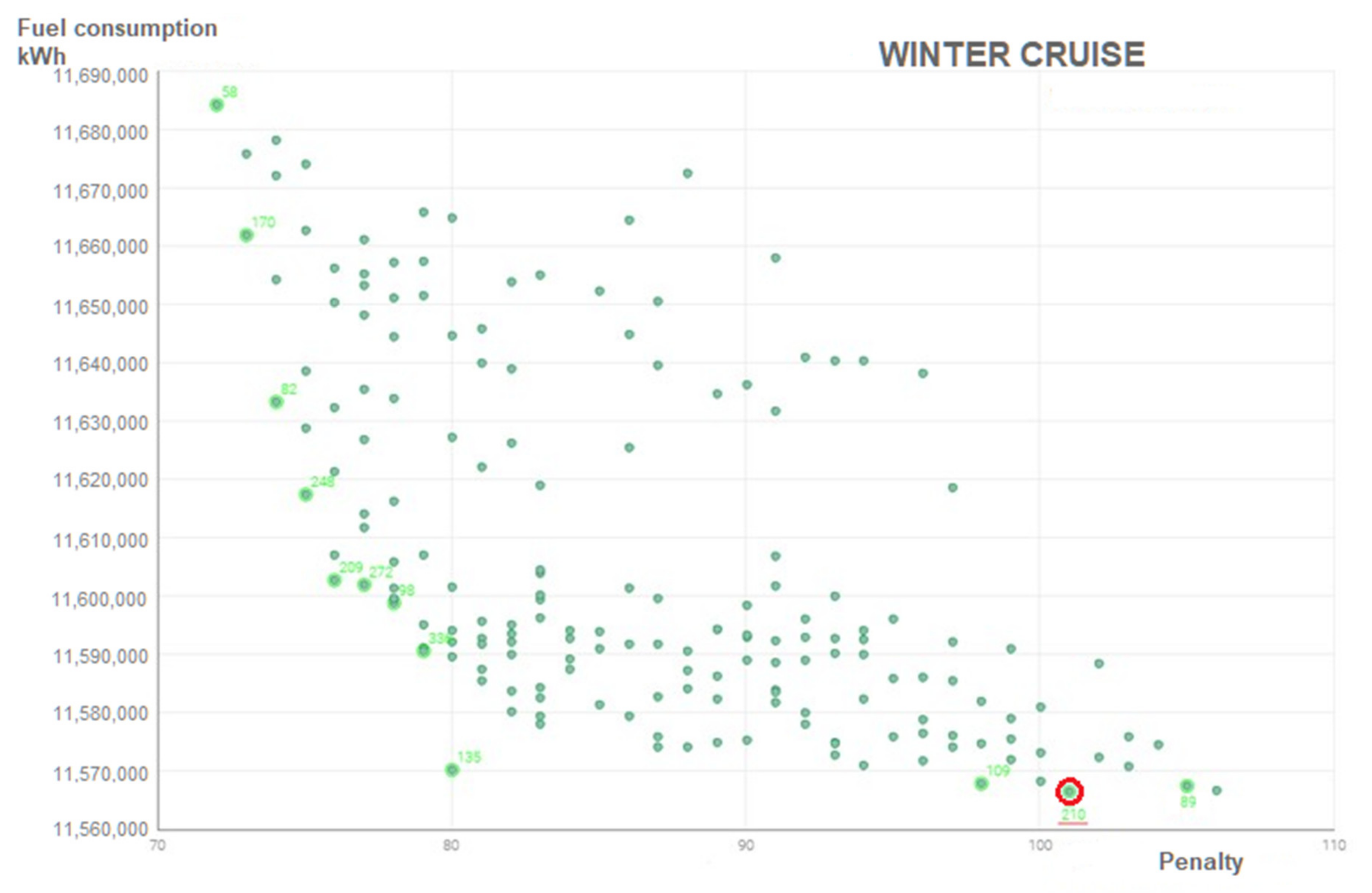
The optimal values identified by the solutions on the Pareto front (Figure 11 and Figure 12) are within the defined ranges and do not show a particular tension towards the upper or lower limits of the ranges, with the exception of the size of the HTW thermal storage in the summer case, whose optimal values tend to stay close to the upper limit of the interval (a peak of the probability density function can be seen in the diagonal of the scattering matrix, Figure 14). Therefore, some extensions of the ranges considered are not expected to improve the solutions on the front.
The different assumptions about the summer and winter reference cruises entail a clear difference in the optimized solutions of the energy recovery system. In particular, the absence of a refrigeration load during the winter cruise makes the absorption chiller useless (and always leaves the compression chiller unused), freeing the thermal power for the operation of the ORC groups, which receive energy from the same thermal carrier (hot water at about 90 °C). In the summer cruise, the using of the absorption chiller is more convenient than the compression one, taking into account the considered efficiency (COP_abs = 0.60; COP_com = 4.00; eta_orc = 0.07), so that the number of ORC groups of 150 kW, installed in the solutions on the Pareto front, is reduced to one, or none.
Figure 11 and Figure 12 show the Pareto front for the summer and winter cases, respectively; the red circle indicates the most interesting solutions from the point of view of reducing consumption. In fact, with reference to the designs considered, it is not advantageous to accept higher penalties because the overall consumption does not drop further, as instead happens in the range 64–88 penalty points for the summer case and in the range 86–112 penalty points for the winter case.
Table 6 shows the values of the main choice variables for the two compromise solutions identified. As can be seen, in the summer case there is an important thermal accumulation, favored by the high value allowed for the thermal flow exchanged with the storage (7000 kW), while there are no ORC groups.
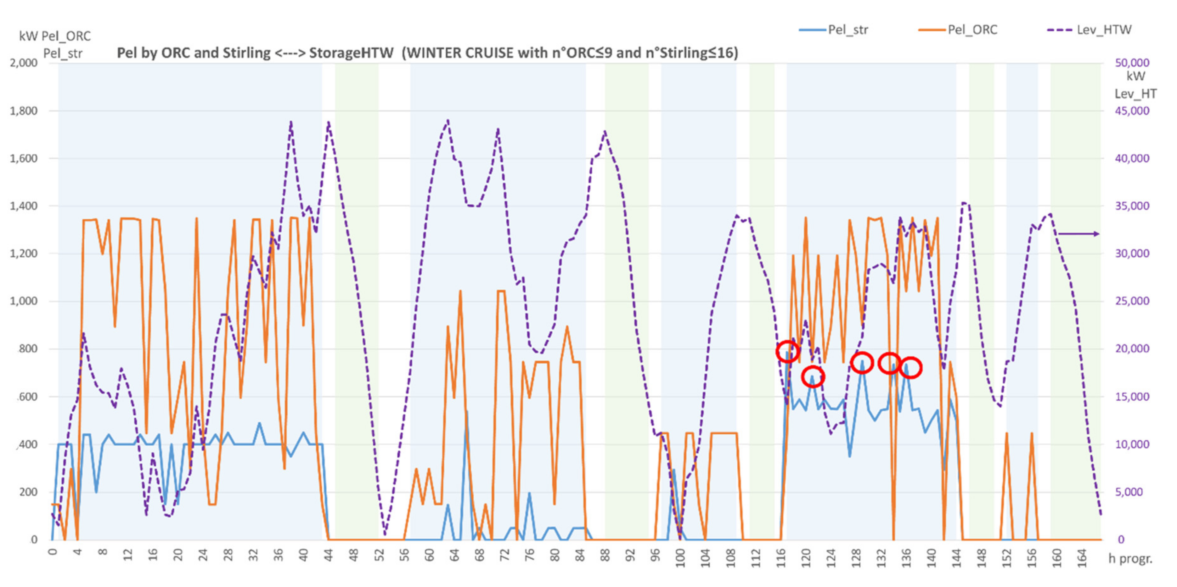
The analysis of the optimized management of the winter case (an example is shown in Figure 13) shows clearly that several excellent solutions on the Pareto front are characterized by a number of Stirlings close to the maximum allowed, but all Stirling units are used only for a very limited number of hours during the cruise.
This consideration leads to take into account the solutions in the area where the slope of the front changes and the number of Stirling groups is close (or coincident) to the lower limit of the interval considered. Consequently, the solution deemed most interesting in the winter case is the ID 210, indicated on the Pareto front with the red circle and shown in Table 6.
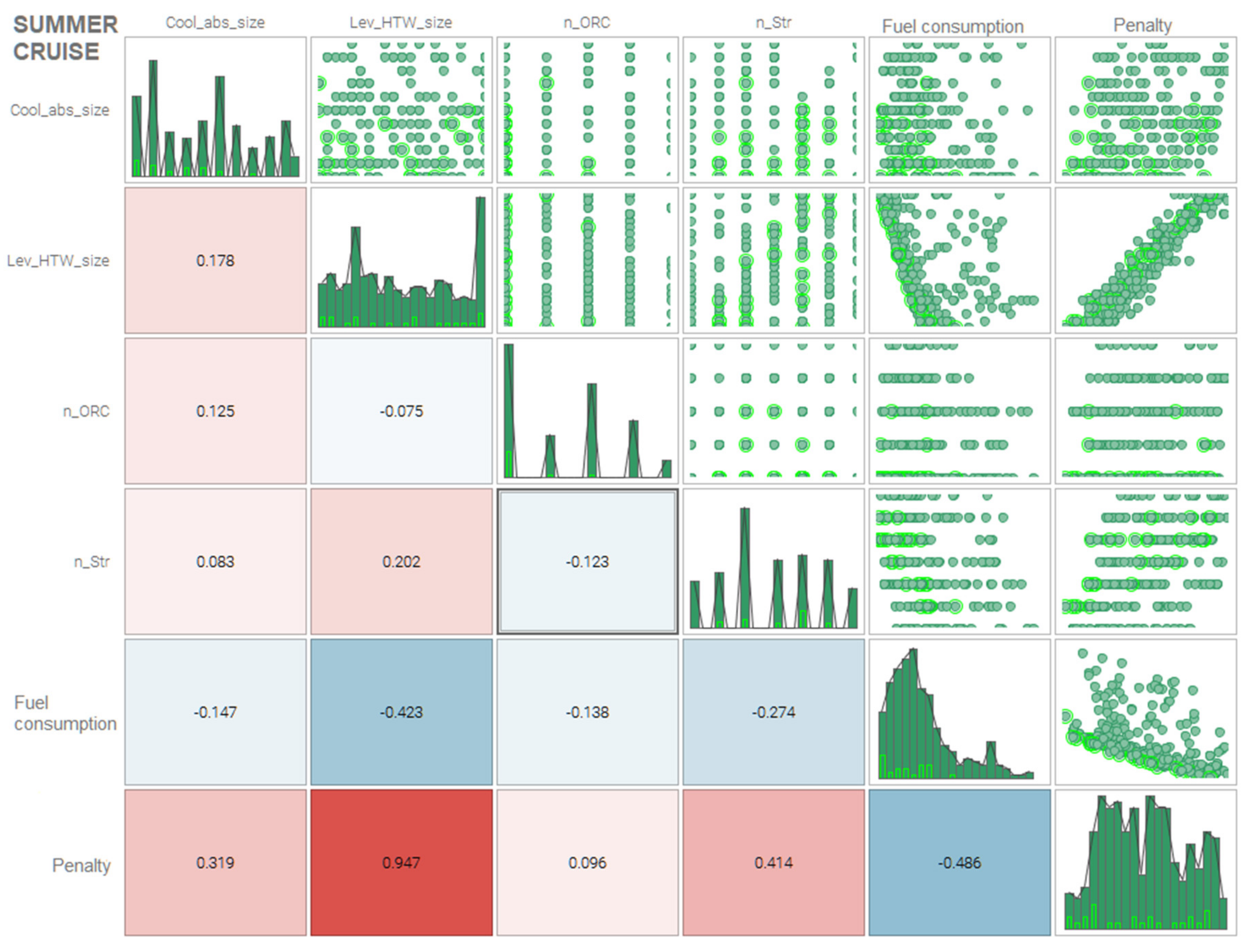
Figure 14 shows the scattering matrix of the solutions analyzed for the summer case. It reports the correlation between the two objectives and the 4 non-null choice variables, managed by the higher level. In particular, the elements along the diagonal show the probability density of the different values of the variables considered, in the population of the individuals analyzed by the genetic algorithm.
The following considerations can be inferred from Figure 14:
  • The size of the HTW thermal storage is the variable that most influences both objectives; it is strictly correlated with the total penalty and rather correlated also with the reduction of the overall fuel consumption.
  • The number of ORC groups, on the other hand, does not affect very much both objectives, even if it contributes to the reduction of fuel consumption. The solution with the highest probability density is zero ORC groups.
  • The number of Stirling groups is strongly influential on both the objectives. It also contributes to constituting the overall value of the penalty.
  • As expected, the two objectives are negatively correlated, in the sense that in most of the designs considered, accepting an increase in the penalty allows a reduction in the fuel consumption. This is no longer true when the penalty value of 89 points is reached, as can be seen from the detail of the Pareto front for the summer case in Figure 11.
Figure 15 shows the scattering matrix of the solutions analyzed for the winter case. It does not contain the variable relating to the size of the absorption chiller, set equal to zero. The considerations that can be drawn from its analysis are similar to those of the summer case, with an evident influence of the size of the HTW thermal storage on the penalty value. It is worth noting that, in this case, that the number of ORC units has a positive effect on the reduction of fuel consumption.
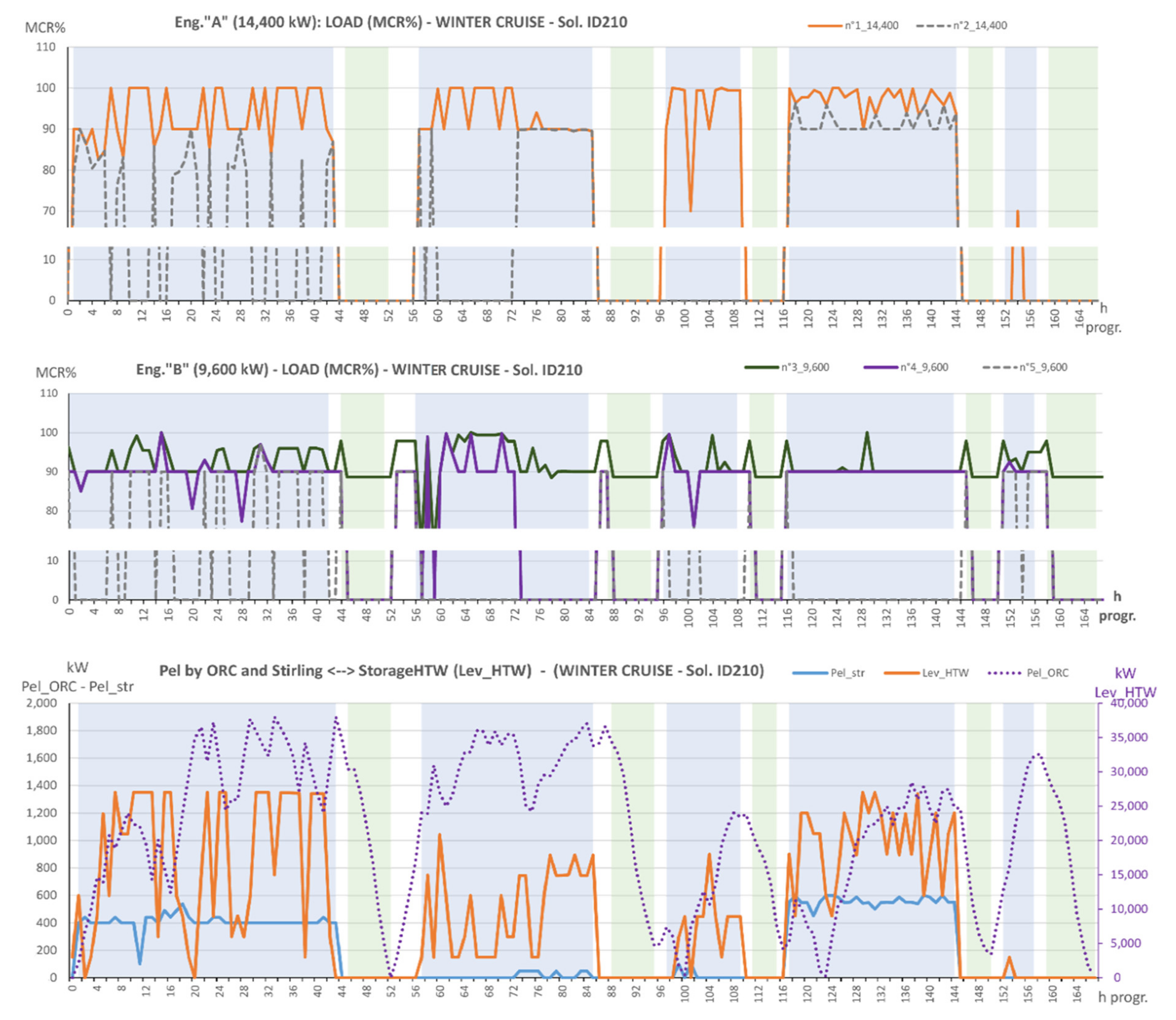
Figure 16 shows, as an example, the results of the optimized management of the ID 210 solution for the winter cruise. The different operational phases of the ship are highlighted with different colors of the background: port green, maneuver white, navigation blue.
The upper part of the figure shows the loads of the two engines type “A” (12V), in the central part of the figure the loads of the three engines “B” (8L) are shown, while the lower part shows the electrical powers produced by the Stirling groups, by the ORC and the thermal energy content in the HTW storage. In particular, the usage of all 12 Stirling groups for a large number of hours can be noted, and compared to the similar case shown in Figure 13.

4.3. Pollutant Emissions Evaluation

For what concern the polluting emissions of the reference ship, the method suggested by Haglind [6] has been followed, which is based on the use of polluting emission factors. In particular, the emission factors depend on the quality of the fuel [62] and on the combustion system, and are expressed as gpollutants/kgFuel. Therefore, the calculations of pollutant emissions can be carried out once the optimization procedure has been completed.
In this approach, the SOx emission factor depends only on the sulfur content of the fuel. Therefore, considering all the sulfur compounds in the exhaust gases as SO2, the emission factor can be calculated as reported in Equation (45):
E F S O x = 20 × % S F u e l   [ g pollutants / kg Fuel ]
The average percentage of sulfur content considered in the calculation is 2.7% and 0.1% respectively for HFO and Marine Gas Oil (MGO), consistently with [63]. Consequently, the SOx emission factors calculated using Equation (45) are 54 gSOx/kgFuel for HFO and 2 gSOx/kgFuel for MGO.
The NOx emission factors are based on the quality of the fuel (HFO or MGO) and the combustion mode (ICE or Oil Fuel Burner-OFB). In the present study, emission factors propose in [64] have been used.
Therefore, once the total fuel quantity (in tons) has been determined, Equation (46) allows us to evaluate the emissions of all types of pollutants:
P E h = E F h × F u e l × 1000   [ g ]
where PEh is the h-th pollutant emission, EFh is the h-th emission factor of pollutant reported previously and Fuel is the total amount of fuel burned in the ICE, or in the OFB.
The efficiency of the abatement devices (SCR and scrubber) must be taken into account, if they are present, obtaining the following two new equations:
P E N O X = E F I C E _ N O X × F u e l I C E × ( 1 η S C R )   [ g ]
P E S O X = E F I C E _ S O X × F u e l I C E × ( 1 η s c r u b b e r )   [ g ]
where EFICE_NOx is the specific NOx emission factor of the ICE, EFICE_SOx is the emission factor by using HFO, ηSCR is the abatement efficiency of the SCR, assumed equal to 85% and ηscrubber is the abatement efficiency of the scrubber, assumed equal to 97%. The latter perform also an important reduction of PM, which can be regarded of about 75%. For what concerns the emissions produced using MGO, the abatement efficacy values equal to 75% of those considered for the HFO have been taken into account, as a precautionary measure.
On the basis of the identified coefficients and abatement efficiencies, the total emissions have been calculated making reference to the ship’s consumption obtained by the optimization procedure. The results obtained for the winter/summer cruises (ID 210/ID 18) are shown in Figure 17 and Figure 18 for the main pollutants, SOx and NOx respectively, also considering different options for the use of fuel and abatement devices, in the various phases of the cruise. In particular, 4 different strategies for the use of fuels have been compared:
A.
HFO for ICE and boilers in all cruising conditions,
B.
HFO for ICE in all cruising conditions and MGO for OFB,
C.
HFO for ICE in navigation and maneuvering and MGO for ICE in port and OFB,
D.
HFO for ICE in navigation and MGO for ICE in maneuvering and in port and for OFB.
All the cases obtained with the optimized designs allow us to obtain total values of the emissions during the cruise, well below the regulatory limits, both for SOx (SECA lim. in Figure 17) and for NOx (NECA lim. in Figure 18).

5. Conclusions

In this research work, a bi-level and multi-objective procedure has been defined for the integrated optimization of the energy recovery and production system on board of a large cruise ship. This procedure is based on an external genetic optimization algorithm, which creates a population of individuals defined by genes, which correspond to the optimization variables that determine the presence or absence of the different components in the super-structure of the energy system. These values are acquired from the internal optimization level, based on a MILP procedure that can be solved with X-Press.
The entire procedure has been implemented in the modeFRONTIER® platform, which allows the Pareto front of the optimization with two objective functions to be easily identify. In particular, fuel consumption during the cruise and an appropriate PENALTY function have been considered. The latter represents the volume occupied by the additional components dedicated to energy recovery.
The use of the modeFRONTIER® platform also allows an easy introduction of the specific inputs of each optimization (for example the range for the variables that represent the number of ORC and Stirling groups) and to perform a statistical analysis on all designs considered through the scattering matrix.
The analysis of the results of the multi-objective optimization indicates that the summer and winter cruises require different solutions to optimize the ship’s integrated energy generation and recovery system. In particular, in the summer solution, the ORC groups are not present or are reduced to a single 150 kW group; on the contrary, in the winter solution, the absence of the absorption chiller allows the use of excess heat to feed 9–10 ORC groups.
Both optimal solutions, on the other hand, show about the same number (18–20) of 50 kW Stirling groups, with a total nominal power of 900–1000 kW.
The hot water thermal storage (at about 90 °C) is very useful for the goal of reducing consumption, even if it involves a significant additional volume occupation; the size of the absorption chiller in the designs on the Pareto front is such as to cover about 90% (or more) of the refrigeration load required. In the summer case, the solutions on the Pareto front frequently show the value of 25,000 kWh for the size of the storage, i.e., the upper limit of the range considered, indicating that an even larger storage (closer to that found for the winter case—40,000 kWh) could allow better results.
Compared to the approximately 11,000,000 kWh of energy estimated for the overall fuel consumption during the reference summer cruise, the reclassification of the thermal loads (consistently with the temperature levels actually required) together with the optimized management of the engine load along the cruise allow the consumption to be reduced to 10,688,000 kWh; the introduction of energy recovery devices allows, considering the ID 18 solution, to further reduce consumption to 10,101,700 kWh, with a saving of 8% compared to the estimated reference and 5.5% compared to the optimal solution, without recovery devices.
Whilst, for the winter cruise, the reclassification of the thermal loads together with the optimized management of the engine load allow to reduce the overall fuel consumption to 11,986,000 kWh, compared to the 12,500,000 kWh estimated for the reference case; the introduction of energy recovery devices allows, considering the ID 210 solution, to further reduce consumption to 11,535,500 kWh, with a saving of 7.5% compared to the estimated reference and more than 3% compared to the optimal solution, without recovery devices.
The decrease (almost 20%) in fuel consumption during the port stops of the summer cruise is certainly significant. It is essentially due to the abundant production of cold by the absorption chillers, the letters also supported by the flows deriving from the hot water storage. The corresponding decrease in the electrical load allows to switch from operating a single type A engine (14,400 kW), with very low load and with high specific consumption, to operating with a type B engine (9600 kW) at a load with better specific consumption and lower emissions.
It should be noted that the reduction in fuel consumption, which can be obtained by adopting the optimized energy recovery devices, is associated with an equal reduction in the emissions produced, during the entire cruise.
The bi-level and multi-objective procedure developed can be easily adapted to optimize the energy system of different ships, or operating on different cruises, and therefore, it represents a useful support tool for the design of increasingly efficient and environmentally friendly ships.

Author Contributions

Conceptualization, P.P. and M.R.; methodology, M.R.; software, P.G. and M.R.; validation, P.G. and M.R.; formal analysis, P.P.; investigation, P.G., P.P. and M.R.; data curation, P.G.; writing—original draft preparation, P.P. and M.R.; writing—review and editing, P.P. and M.R.; supervision, P.P. and M.R.; funding acquisition, M.R. All authors have read and agreed to the published version of the manuscript.

Funding

This research was funded by CNR-DIITET, grant prot. number 1401/2017.

Acknowledgments

The authors are grateful to Fincantieri S.p.A. for having allowed to access the data necessary to carry out this research and to Bianca Vaglieco (CNR Napoli) for useful discussions and suggestions.

Conflicts of Interest

The authors declare no conflict of interest. The funders had no role in the analyses, interpretation of data; in the writing of the manuscript and in the decision to publish the results.

Nomenclature

Acronyms
ACabsorption chillers
Bliquid fuel
BOSbalance of System for the photovoltaic panels
CCcompression chillers
CHP-CCHPcombined heating and power—combined cooling heating and power
CWdchilled water demand
CWSchilled water storage
DD. GGmain diesel engines
EGexhaust gases
EGRSexhaust gases recovery system
EGTexhaust gas treatment
EEelectric energy
EEdelectric energy demand
FWdfresh water demand
FWSfresh water storage
HFOheavy fuel oil
HThigh temperature
HTWhot water boilers
HTWdhot water demand
HVACAir conditioning
ICEinternal combustion engine
IMOInternational Maritime Organization
LNGliquefied natural gas
LTlow temperature
LTWdlow temperature water demand
MARPOLshort for International Convention for the Prevention of Pollution from Ships
MILPMGOmixed integer linear programmingMarine Gas Oil
ODFWOFBreverse osmosis desalinatorOil Fuel Burner
ORCorganic Rankine cycle
PVphotovoltaic panels
Sstema
SBsteam boilers
SCRselective catalytic reduction device
Sdsteam demand
SECAsulfur emission control areas
SSsteam storage
STsolar thermal collectors
StirlStirling unit
TDthermal dissipater
TGgas turbine
TSthermal storages
Symbols
Apvsolar photovoltaic panels surface[m2]
Astsolar thermal collectors surface[kW]
Cool_absabsorption chillers cooling power[kW]
Cool_comcompression chillers cooling power
Cool_abs_sizeabsorption chillers size[kW]
Cool_com_sizecompression chillers size[kW]
EFhgeneric pollutant emission factor[gpollutants/kgFuel]
EFNOxNOx emission factor[gNOx/kgFuel]
EFSOxSOx emission factor[gSOx/kgFuel]
eta_elelectric efficiency
eta_HTWwater boilers integrative thermal efficiency
eta_orcORC electrical efficiency
eta_Ststeam integrative thermal efficiency
eta_strStirling electrical efficiency
ER usersthermal power for engine rooms[kW]
Fuelengine fuel consumption[kW]
Fuel_BHtfuel consumption of integrative water boilers[kW]
Fuel_BStfuel consumption of integrative steam[kW]
Fuel_TOTtotal fuel consumption[kWh]
ggeneric day
GNpvphotovoltaic panel data vector[W/m2]
GNstsolar collector data vector[W/m2]
Hexgheat recovered from the ICE gases[kW]
Hexg_strthermal input of Stirling groups[kW]
HThheat recovered in form of HTW[kW]
HTh_absthermal input of absorption chillers[kW]
HTh_orcthermal input of ORC groups[kW]
Hotel NOT Hot waterthermal power for swimming pool heaters and laundry[kW]
Hotel ONLY- HotWaterthermal power for sanitary use[kW]
igeneric hour
Input_CWpower input in the chilled water storage[kW]
Input_HTWpower input into the HTW storage[kW]
Input_Stpower input in the steam storage[kW]
Int_HTWwater boilers integrative thermal power[kW]
Int_Ststeam integrative thermal power[kW]
jgeneric ICE
Lev_HTWenergy stored in HTW storage[kWh]
Lev_HTW_sizeenergy stored size in HTW storage[kWh]
Lev_Stenergy stored in the steam storage[kWh]
Lev_St_sizeenergy stored size in the steam storage[kWh]
MCR%engine load as a percentage of the nominal load[%]
OBJFuncgeneral objective function[kWh]
Ouput_CWpower output in the chilled water storage[kW]
Output_HTWpower output in the HTW storage[kW]
Output_Stpower output in the steam storage[kW]
PEhgeneric pollutant emission[gpollutants]
PENOxNOx emission[gNOx]
PESOxSOx emission[gSOx]
Pel/Pelectelectrical power[kW]
Pel_comcompression chillers electrical power[kW]
Pel_orcORC electrical power[kW]
Pel_strStirling electrical power[kW]
PEN_abspenalty function for absorption chillers[pt/kW]
PENALTYpenalty function[pt]
PENconvpenalty function conversion factor[kWh/pt]
PEN_HTWpenalty function for HTW[pt/kWh]
PEN_orcpenalty function for ORC groups[pt]
PEN_stpenalty function for solar thermal collectors[pt/m2]
PEN_STpenalty function for steam storage[pt/kW]
PEN_strpenalty function for Stirling groups[pt]
PEN_pvpenalty function for photovoltaic panels[pt/m2]
P HVACpower for air conditioning[kW]
PPODpower for the POD propulsion system[kW]
Ppvsolar photovoltaic panels power[kW]
P pumps - galleylights: power for hotel use and aux systems[kW]
Pstsolar thermal collector power[kW]
P technicalpower for non-propulsive technical uses[kW]
Qexh.gasheat recoverable from the exhaust gases of the ICEs[kW]
QHT-TOTrecovheat recoverable from the hot water circuit of the ICE[kW]
RICELelectric power required[kW]
RICCOOLcooling power required as chilled water at 8 °C[kW]
RICTER_HTWheat required as hot water at 60–90 °C[kW]
RICTER_Stheat required as saturated steam at 10 bar and 180 °C[kW]
SttoHTWthermal power from the Steam to the HTW line[kW]
Tank Heatingthermal power for treatment of fuel, sludge, etc.[kW]
X_orcORC existence
X_strStirling existence
yON/OFF condition of ICEs
y_orcON/OFF condition of ORC groups
y_Input_HTWON/OFF condition of the flow entering the HTW storage
y_Input_StON/OFF condition of the flow entering the steam storage
y_Output_HTWON/OFF condition of the output stream in the HTW storage
y_Output_StON/OFF condition of the output stream in the steam storage
y_strON/OFF condition of Stirling groups
ηSCRSCR abatement efficiency
ηscrubberscrubber abatement efficiency

References

  1. International Maritime Organization. MARPOL 73/78; Annex VI; International Maritime Organization: London, UK, 1997. [Google Scholar]
  2. Maragkogianni, A.; Papaefthimiou, S. Evaluating the social cost of cruise ships air emissions in major ports of Greece. Transp. Res. Part. D Transp. Environ. 2015, 36, 10–17. [Google Scholar] [CrossRef]
  3. Azzara, A.A.; Rutherford, D.; Wang, H. Feasibility of IMO Annex VI Tier III implementation using selective catalytic reduction. Int. Counc. Clean Transp. 2014, 4, 1–9. [Google Scholar]
  4. Armellini, A.; Daniotti, S.; Pinamonti, P.; Reini, M. Evaluation of Gas Turbines as alternative energy production systems for a large cruise ship to meet new maritime regulations. Appl. Energy 2018, 211, 306–317. [Google Scholar] [CrossRef] [Green Version]
  5. Armellini, A.; Daniotti, S.; Pinamonti, P.; Reini, M. Reducing the environmental impact of large cruise ships by the adoption of complex cogenerative/trigenerative energy systems. Energy Convers. Manag. 2019, 198, 1–11. [Google Scholar] [CrossRef]
  6. Haglind, F. A review on the use of gas and steam turbine combined cycles as prime movers for large ships. Part II: Previous work and implications. Energy Convers. Manag. 2008, 49, 3468–3475. [Google Scholar] [CrossRef]
  7. Geertsma, R.D.; Negenborn, R.R.; Visser, K.; Hopman, J.J. Design and control of hybrid power and propulsion systems for smart ships: A review of developments. Appl. Energy 2017, 194, 30–54. [Google Scholar] [CrossRef]
  8. Xiao, N.; Zhou, R.; Lin, X. Type selection and design of hybrid propulsion system of ship. In IOP Conference Series: Materials Science and Engineering, Proceedings of the 2016 Second International Conference on Mechanical Engineering and Automation Science (ICMEAS 2016), Singapore, 13–15 October 2016; IOP Publishing: Philadelphia, PA, USA, 2016; Volume 157. [Google Scholar] [CrossRef] [Green Version]
  9. Lloyd’s Register. LNG-Fuelled Deep Sea Shipping; Lloyd’s Register: London, UK, 2012. [Google Scholar]
  10. Banawan, A.A.; El Gohary, M.M.; Sadek, I.S. Environmental and economical benefits of changing from marine diesel oil to natural-gas fuel for short-voyage high-power passenger ships. Proc. Inst. Mech. Eng. Part M J. Eng. Marit. Environ. 2010, 224, 103–113. [Google Scholar] [CrossRef]
  11. Burel, F.; Taccani, R.; Zuliani, N. Improving sustainability of maritime transport through utilization of liquefied natural gas (LNG) for propulsion. Energy 2013, 57, 412–420. [Google Scholar] [CrossRef]
  12. Ballini, F.; Bozzo, R. Air pollution from ships in ports: The socio-economic benefit of cold-ironing technology. Res. Transp. Bus. Manag. 2015, 17, 92–98. [Google Scholar] [CrossRef]
  13. Tien, W.K.; Yeh, R.H.; Hong, J.M. Theoretical analysis of cogeneration system for ships. Energy Convers. Manag. 2007, 48, 1965–1974. [Google Scholar] [CrossRef]
  14. Dzida, M. Possible efficiency increasing of ship propulsion and marine power plant with the system combined of marine diesel engine, gas turbine and steam turbine. Adv. Gas Turbine Technol. 2011, 45–68. [Google Scholar] [CrossRef] [Green Version]
  15. Nielsen, R.F.; Haglind, F.; Larsen, U. Design and modeling of an advanced marine machinery system including waste heat recovery and removal of sulphur oxides. Energy Convers. Manag. 2014, 85, 687–693. [Google Scholar] [CrossRef] [Green Version]
  16. Michos, C.N.; Lion, S.; Vlaskos, I.; Taccani, R. Analysis of the backpressure effect of an organic rankine cycle (ORC) evaporator on the exhaust line of a turbocharged heavy duty diesel power generator for marine applications. Energy Convers. Manag. 2017, 132, 347–360. [Google Scholar] [CrossRef]
  17. Yang, F.; Dong, X.; Zhang, H.; Wang, Z.; Yang, K.; Zhang, J.; Wang, E.; Liu, H.; Zhao, G. Performance analysis of waste heat recovery with a dual loop organic rankine cycle (ORC) system for diesel engine under various operating conditions. Energy Convers. Manag. 2014, 80, 243–255. [Google Scholar] [CrossRef]
  18. Bonafin, J.; Pinamonti, P.; Reini, M.; Tremuli, P. Performance improving of an internal combustion engine for ship propulsion with a bottom ORC. In Proceedings of the ECOS 2010 ECOS 2010—23rd International Conference on Efficiency, Cost, Optimization, Simulation, and Environmental Impact of Energy Systems, Lausanne, Switzerland, 14–17 June 2010. [Google Scholar]
  19. Mondejar, M.E.; Ahlgren, F.; Thern, M.; Genrup, M. Quasi-steady state simulation of an organic rankine cycle for waste heat recovery in a passenger vessel. Appl. Energy 2017, 185, 1324–1335. [Google Scholar] [CrossRef]
  20. Yang, M.H.; Yeh, R.H. Thermodynamic and economic performances optimization of an organic rankine cycle system utilizing exhaust gas of a large marine diesel engine. Appl. Energy 2015, 149, 1–12. [Google Scholar] [CrossRef]
  21. Rech, S.; Zandarin, S.; Lazzaretto, A.; Frangopoulos, C.A. Design and off-design models of single and two-stage ORC systems on board a LNG carrier for the search of the optimal performance and control strategy. Appl. Energy 2017, 204, 221–241. [Google Scholar] [CrossRef]
  22. Aladayleh, W.; Alahmer, A. Recovery of exhaust waste heat for ice using the beta type stirling engine. J. Energy 2015, 2015, 1–8. [Google Scholar] [CrossRef] [Green Version]
  23. Larsen, H.V.; Bøhm, B.; Wigbels, M. A comparison of aggregated models for simulation and operational optimisation of district heating networks. Energy Convers. Manag. 2004, 45, 1119–1139. [Google Scholar] [CrossRef]
  24. Consonni, S.; Lozza, G.; Macchi, E. Optimization of a cogeneration systems operation Part A: Prime movers modelization. In Proceedings of the ASME Cogen-Turbo ’89, Nice, France, 30 August–1 September 1989; pp. 313–322. [Google Scholar]
  25. Consonni, S.; Lozza, G.; Macchi, E. Optimization of a cogeneration systems operation Part B: Solution algorithm and examples of optimum operating strategies. In Proceedings of the ASME Cogen-Turbo ’89, Nice, France, 30 August–1 September 1989; pp. 323–331. [Google Scholar]
  26. Yokoyama, R.; Ito, K. Operational strategy of a cogeneration system under a complex utility rate structure. J. Energy Resour. Technol. 1996, 118, 256–262. [Google Scholar] [CrossRef]
  27. Yokoyama, R.; Ito, K.; Kamimura, K.; Miyasaja, F. Development of a general purpose optimal operational planning system for energy supply plants. J. Energy Resour. Technol. 1994, 116, 290–296. [Google Scholar] [CrossRef]
  28. Yokoyama, R.; Ito, K. A revised decomposition method for MILP problems and its application to operational planning of thermal storage systems. J. Energy Resour. Technol. 1996, 118, 277–284. [Google Scholar] [CrossRef]
  29. Casisi, M.; Pinamonti, P.; Reini, M. Optimal lay-out and operation of CHP distributed generation systems. Energy 2009, 34, 2175–2183. [Google Scholar] [CrossRef]
  30. Buoro, D.; Casisi, M.; Pinamonti, P.; Reini, M. Optimal lay-out and operation of district heating and cooling distributed trigeneration systems (GT2010-23416). In Proceedings of the AMSE TurboExpo 2010, Glasgow, UK, 14–18 June 2010. [Google Scholar]
  31. Buoro, D.; Pinamonti, P.; Reini, M. Optimization of a distributed cogeneration system with solar district heating. Appl. Energy 2014, 124, 298–308. [Google Scholar] [CrossRef]
  32. Casisi, M.; Pinamonti, P.; De Nardi, A.; Reini, M. Effect of different economic support policies on the optimal synthesis and operation of a distributed energy supply system with renewable energy sources for an industrial area. Energy Convers. Manag. 2015, 95, 131–139. [Google Scholar] [CrossRef]
  33. Steen, D.; Stadler, M.; Cardoso, G.; Groissböck, M.; DeForest, N.; Marnay, C. Modeling of thermal storage systems in MILP distributed energy resource models. Appl. Energy 2015, 137, 782–792. [Google Scholar] [CrossRef] [Green Version]
  34. Pohekar, S.D.; Ramachandran, M. Application of multi-criteria decision making to sustainable energy planningA review. Renew. Sustain. Energy Rev. 2004, 8, 365–381. [Google Scholar] [CrossRef]
  35. Wang, J.J.; Jing, Y.Y.; Zhang, C.F.; Zhao, J.H. Review on multi-criteria decision analysis aid in sustainable energy decision making. Renew. Sustain. Energy Rev. 2009, 13, 2263–2278. [Google Scholar] [CrossRef]
  36. Alarcón, A.; Ault, G.; Galloway, S. Multi-objective planning of distributed energy resources a review of the state-of-the-art. Renew. Sustain. Energy Rev. 2010, 14, 1353–1366. [Google Scholar] [CrossRef]
  37. Lazzaretto, A.; Toffolo, A. Energy, economy and environment as objectives in multi-criterion optimization of thermal systems design. Energy 2004, 29, 1139–1157. [Google Scholar] [CrossRef]
  38. Tsay, M.T. Applying the multi-objective approach for operation strategy of cogeneration systems under environmental constraints. Int. J. Electr. Power Energy Syst. 2003, 25, 219–226. [Google Scholar] [CrossRef]
  39. Kavvadias, K.C.; Maroulis, Z.B. Multi-objective optimization of a trigeneration plant. Energy Policy 2010, 38, 945–954. [Google Scholar] [CrossRef]
  40. Buoro, D.; Casisi, M.; De Nardi, A.; Pinamonti, P.; Reini, M. Multicriteria optimization of a distributed energy supply system for an industrial area. Energy 2013, 58, 128–137. [Google Scholar] [CrossRef]
  41. Ren, H.; Zhou, W.; Nakagami, K.; Gao, W.; Wu, Q. Multi-objective optimization for the operation of distributed energy systems considering economic and environmental aspects. Appl. Energy 2010, 87, 3642–3651. [Google Scholar] [CrossRef]
  42. Buoro, D.; Casisi, M.; Pinamonti, P.; Reini, M. Optimization of distributed trigeneration system integrated with district heating and cooling micro-grids. Distrib. Gener. Altern. Energy J. 2011, 26, 7–33. [Google Scholar]
  43. Buoro, D.; Casisi, M.; Pinamonti, P.; Reini, M. A comparison of different district integration for a distributed generation system for heating and cooling in an urban area. Appl. Sci. 2019, 9, 1–40. [Google Scholar]
  44. Ito, K.; Akagi, S. An optimal planning method for a marine heat and power generation plant by considering its operational problem. Int. J. Energy Res. 1986, 10, 75–85. [Google Scholar] [CrossRef]
  45. Dai, R.; Mesbahi, M. Optimal power generation and load management for off-grid hybrid power systems with renewable sources via mixed-integer programming. Energy Convers. Manag. 2013, 73, 234–244. [Google Scholar] [CrossRef]
  46. Trivyza, N.L.; Rentizelas, A.; Theotokatos, G. A novel multi-objective decision support method for ship energy systems synthesis to enhance sustainability. Energy Convers. Manag. 2018, 168, 128–149. [Google Scholar] [CrossRef] [Green Version]
  47. Skjong, E.; Johansen, T.A.; Molinas, M.; Sørensen, A.J. Approaches to economic energy management in diesel-electric marine vessels. IEEE Trans. Transp. Electrif. 2017, 3, 22–35. [Google Scholar] [CrossRef] [Green Version]
  48. Dimopoulos, G.G.; Kougioufas, A.V.; Frangopoulos, C.A. Synthesis, design and operation optimization of a marine energy system. Energy 2008, 33, 180–188. [Google Scholar] [CrossRef]
  49. Gao, D.; Wang, X.; Wang, T.; Wang, Y.; Xu, X. An energy optimization strategy for hybrid power ships under load uncertainty based on load power prediction and improved NSGA-II algorithm. Energies 2018, 11, 1699. [Google Scholar] [CrossRef] [Green Version]
  50. Baldi, F.; Ahlgren, F.; Van Nguyen, T.; Thern, M.; Andersson, K. Energy and Exergy Analysis of a Cruise Ship. Energies 2018, 11, 2508. [Google Scholar] [CrossRef] [Green Version]
  51. Yan, Y.; Zhang, H.; Long, Y.; Wang, Y.; Liang, Y.; Song, X.; Yu, J.J.Q. Multi-objective design optimization of combined cooling, heating and power system for cruise ship application. J. Clean. Prod. 2019, 233, 264–279. [Google Scholar] [CrossRef]
  52. Casisi, M.; Costanzo, S.; Pinamonti, P.; Reini, M. Two-level evolutionary multi-objective optimization of a district heating system with distributed cogeneration. Energies 2019, 12, 114. [Google Scholar] [CrossRef] [Green Version]
  53. Zentilomo, L. (Fincantieri S.p.A., Trieste, Italy). Personal Communication about ship energy demand. 2019. [Google Scholar]
  54. EPRI. Stirling Engine Assessment; EPRI: Washington, DC, USA, 2002. [Google Scholar]
  55. Ballesteros, M.; Pujol, M.; Walsh, F.; Teubner, J. Geothermal Energy Electricity Generation in Australia: Recent Developments and Future Potential; Technical Report; Australian Geothermal Association: Adelaide, Australia, 2019; Available online: https://www.researchgate.net/publication/338384566 (accessed on 1 April 2020).
  56. Available online: http://www.energiazero.org/solare_termico/curva_efficienza_collettore_solare.pdf (accessed on 1 April 2020).
  57. Joudi, K.A.; Lafta, A.H. Simulation of a simple absorption refrigeration system. Energy Convers. Manag. 2001, 42, 1575–1606. [Google Scholar] [CrossRef]
  58. Climaveneta. Water Cooled Liquid Chillers TECS-HF; Climaveneta: Bassano del Grappa, Italy, 2006. [Google Scholar]
  59. Deb, K.; Pratap, A.; Agarwal, S.; Meyarivan, T. A fast and elitist multiobjective genetic algorithm: NSGA-II. IEEE Trans. Evol. Comput. 2002, 6, 182–197. [Google Scholar] [CrossRef] [Green Version]
  60. Frangopoulos, C.A.; von Spakovsky, M.R.; Sciubba, E. A Brief review of methods for the design and synthesis optimization of energy systems. Int. J. Appl. Thermodyn. 2002, 5, 151–160. [Google Scholar]
  61. Muñoz, R.J.; von Spakovsky, M.R. A Decomposition Approach for the large scale synthesis/design optimization of highly coupled, highly dynamic energy systems. Int. J. Appl. Thermodyn. 2001, 4, 19–33. [Google Scholar]
  62. Mueller, L.; Jakobi, G.; Czech, H.; Stengel, B.; Orasche, J.; Arteaga-Salas, J.M.; Karg, E.; Elsasser, M.; Sippula, O.; Streibel, T.; et al. Characteristics and temporal evolution of particulate emissions from a ship diesel engine. Appl. Energy 2015, 155, 204–217. [Google Scholar] [CrossRef]
  63. Endresen, Ø.; Sørgård, E.; Sundet, J.K.; Dalsøren, J.S.B.; Isaksen, I.S.A.; Berglen, T.F.; Gravir, G. Emission from international sea transportation and environmental impact. J. Geophys. Res. 2003, 108, 1–22. [Google Scholar] [CrossRef]
  64. Trozzi, C.; De Lauretis, R. EMEP/EEA Air Pollutant Emission Inventory Guidebook 2019; European Environment Agency: Copenhagen, Denmark, 2019. [Google Scholar]
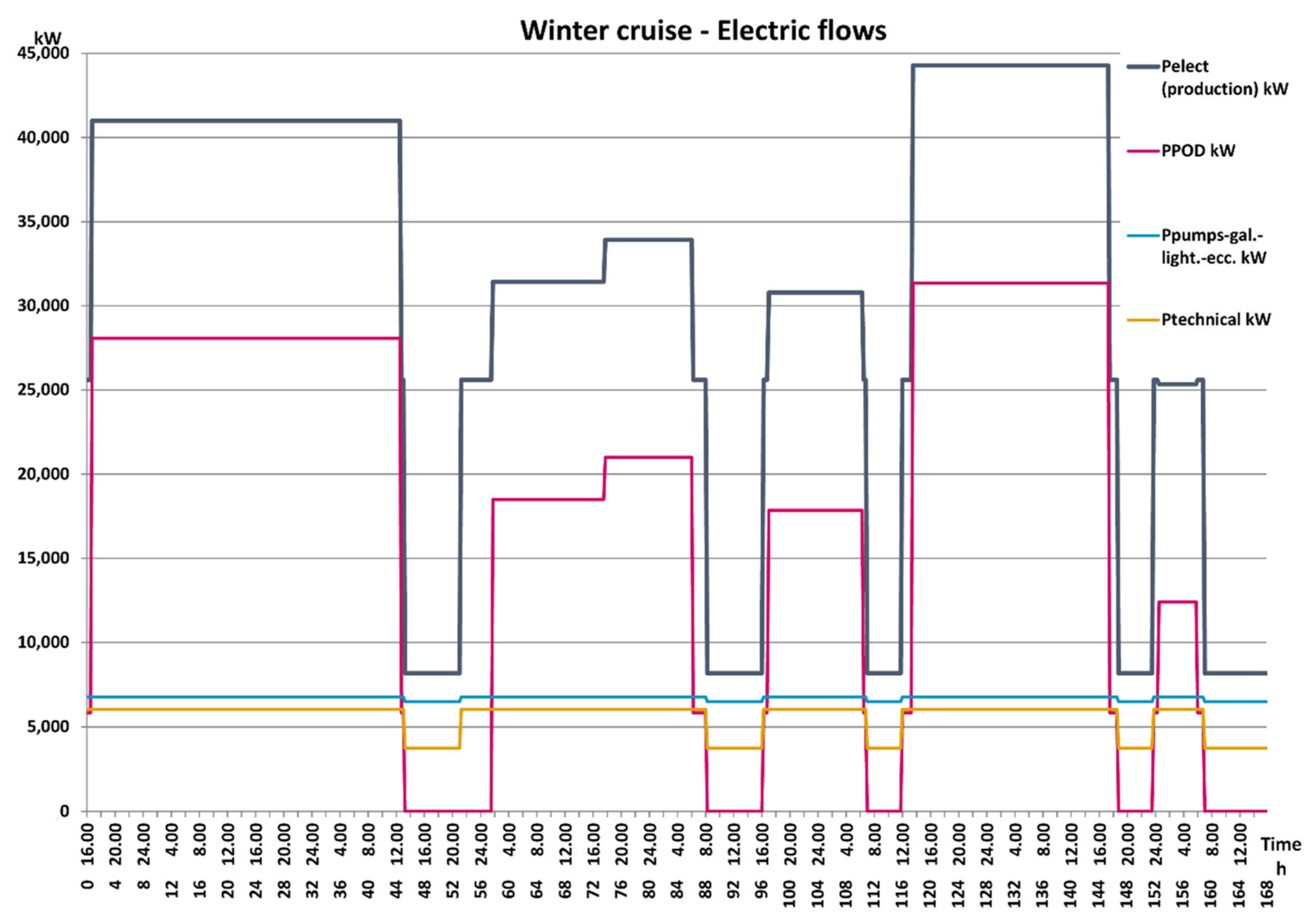
Figure 1. Electrical demand during the winter cruise.
Applsci 10 06917 g001
Figure 2. Electrical demand during the summer cruise.
Applsci 10 06917 g002
Figure 3. Thermal demand during the winter cruise.
Applsci 10 06917 g003
Figure 4. Thermal demand during the summer cruise.
Applsci 10 06917 g004
Figure 5. Super-structure of the on board energy system.
Applsci 10 06917 g005
Figure 6. Operating curves of the Internal Combustion Engine (ICE) 12V, with the linearized equations.
Applsci 10 06917 g006
Figure 7. Operating curves of the ICE 8L, with the linearized equations.
Applsci 10 06917 g007
Figure 8. Scheme of the bi-level optimization procedure.
Applsci 10 06917 g008
Figure 9. Scheme of the mixed-integer linear programming model of the system (MILP) procedure at the internal level.
Applsci 10 06917 g009
Figure 10. Work flow of the optimization algorithm in the modeFRONTIER® environment.
Applsci 10 06917 g010
Figure 11. Pareto front of the optimal solutions in the summer case. The red circle indicates the most interesting solutions from the point of view of reducing consumption.
Applsci 10 06917 g011
Figure 12. Pareto front of the optimal solutions in the winter case. The red circle indicates the most interesting solutions from the point of view of reducing consumption.
Applsci 10 06917 g012
Figure 13. An example of optimized management, with 16 Stirling groups for the winter case; in the red circles the time interval of the cruise during which 16 or 15 or 14 Stirling groups are actually used.
Applsci 10 06917 g013
Figure 14. Scattering matrix of the solutions analyzed for the summer case.
Applsci 10 06917 g014
Figure 15. Scattering matrix of the solutions analyzed for the winter case.
Applsci 10 06917 g015
Figure 16. Results for the optimized management of the ID 210 solution (winter case).
Applsci 10 06917 g016
Figure 17. SOx emissions values, calculated for the winter/summer cruise, with different strategies for the usage of fuel and abatement devices.
Applsci 10 06917 g017
Figure 18. NOx emissions values, calculated for the winter/summer cruise, with different strategies for the usage of fuel and abatement devices.
Applsci 10 06917 g018
Table 1. Performance curve data of a vacuum tube collector Sunwood SW15/20 [56].
Optical Efficiency[%]67.9
Characteristic Parameter a1[W/m2 K]1.696
Characteristic Parameter a2[W/m2 K2]0.0099
Table 2. Functions of the nodes in the graphical workflow in Figure 10.
n_Str; n_ORCDefining of the variation range for the optimization variables actual number of Stirling groups and actual number of ORC groups.
Lev_HTW_size; Lev_St_size; Cool_abs_size; Cool_com_size; Apv; AstDefining of the variation range for the other optimization variables, size of HTW thermal storage, size of the steam storage, size of the absorption chiller, size of the compression chiller, area of the solar panels, area of the solar thermal collectors.
SchedulingStartDefining of the optimization algorithm for the external level (NSGA-II) and setting of the parameters for the formulation of the different generations, in particular the number of individuals, the number of generations and the population of the first generation.
Calculator 14Converting of the number of Stirling groups and of the number of ORC groups into the vectors X_str (stirling) and X_orc (ORC).
SupportFile2Calling the COMPONENTS.dat (Figure 9) file which contains the characteristics chosen for the components (in particular the efficiencies of the Stirling and ORC groups) and makes it available for the subsequent EasyDriver1 node.
STIR; ORCContaining the vectors X_str (stirling) and X_orc (ORC) produced by the node Calculator 14.
EasyDriver1It is the main node of the workflow; it defines the modeF.dat file (Figure 9) that can be read by the MILP procedure, launches the genetic procedure and writes the output containing the values of all the variables, calculated internally by the MILP procedure, and of the two objectives for all the individuals, until the end of the procedure.
OutputScalar31; OutputScalar17Identifying, in the output of the EasyDriver1 node, the two scalar values corresponding to the fuel consumption and to the penalty associated with the choice of variables managed by the external level.
Objective32; Objective18Identifying the two variables highlighted by nodes OutputScalar31 and OutputScalar17 as objectives to be minimized.
Exit4Defining the end of the procedure of design evolution, when all the generations set in the SchedulingStart node have been examined.
Table 3. Main design variables, with their variation ranges and penalty coefficients.
VariablesRef. Value or RangeUnitsPenalty FunctionPenalty Ref. Value or RangeUnits
Max number of Stirling10–40-PEN_str1[10 m3]
Max number of ORC10–25-PEN_orc1[10 m3]
COP_abs0,60----
Pel_strsup50[kW]---
Pel_orcsup150[kW]---
Cool_abs_max10[MW]PENabs1/360[10 m3/kW]
Int_HTW_max10[MW]---
Input/Output_HTW_Max1–7[MW]PEN_HTW0.002[10 m3/kW]
ApvMax1000[m2]PENpv1/80–1/320[10 m3/m2]
AstMax500[m2]PENst1/50–1/200[10 m3/m2]
Table 4. Main results obtained by the preliminary optimization, agreeing with the ranges of Table 3.
Variation in the Max Number of Stirling Groups
n° Stirling max (gap%)ORC tot_sizeStirling tot_sizeAbsorber sizeHTW storage sizeFuelTotPenaltyStirling productionORC productionBoiler integration SteamBoiler integration HTWHTW Input to Storage
kWkWkWkWhkWh10m3kWhkWhkWhkWhkWh
10 (1.0)6005008000495310,292,40046.1358,85310,75746,55854,67751,557
20 (1.0)15010008000495310,214,60053.13100,791313259,50256,55452,263
30 (1.5)014008000495310,213,70060.13124,754058,82850,17157,917
40 (2.0)017008000495310,149,70066.13121,791057,43451,66256,622
Variation in the max number of ORC groups
n° ORC max (gap%)ORC tot_sizeStirling tot_sizeAbsorber sizeHTW storage sizeFuelTotPenaltyStirling productionORC productionBoiler integration SteamBoiler integration HTWHTW Input to Storage
kWkWkWkWhkWh10m3kWhkWhkWhkWhkWh
5 (1.0)15010008000495310,214,60053.13100,791313259,50256,55452,263
10 (1.0)30010008000495310,212,30054.13103,528104373,20459,83242,410
15 (1.0)30010008000471510,216,50053.65101,786388060,54154,76353,023
20 (1.0)15010008000495310,219,10053.13107,468284176,59956,53754,280
Variation of the max Input/Output flow value of the HTW Storage
in/out max (gap%)ORC tot_sizeStirling tot_sizeAbsorber sizeHTW storage sizeFuelTotPenaltyStirling productionORC productionBoiler integration SteamBoiler integration HTWHTW Input to Storage
kWkWkWkWkWhkWh10m3kWhkWhkWhkWhkWh
1000 (1.0)15010008000495310,214,60053.13100,790313259,50256,55452,264
3000 (1.0)30010008000988610,179,70064.00103,380223874,17037,493101,848
5000 (1.0)3001000800010,53510,176,40065.30100,234462956,47731,128164,176
7000 (1.0)3001000800011,39210,148,30067.0199,468641855,25330,831233,284
Table 5. Ranges for the optimization variables managed by the external level.
CruiseSummerWinter
Range of Stirling groups15–2012–20
Range of ORC groups0–36–12
Solar panel area Apv [m2]zerozero
Solar thermal collector area Ast [m2]zerozero
Absorption chiller size, Cool_abs_size [kW]7–8000zero
Compression chiller size, Cool_com_size [kW]20002000
Steam storage size, Lev_St_size [kWh]zerozero
HTW storage size Lev_HTW_size [kWh]15–25,00030–50,000
Table 6. Optimal compromise solutions identified on the Pareto fronts (Figure 11 and Figure 12).
IDn° ORCn° StirlingAbsorber
Size
HTW
Storage Size
Fuel
ICE
PenaltyStirling
Product
ORC ProductFuel Int. for SteamFuel Int. for HTW
--[kWh][kWh][t][10 m3][kWh][kWh][t][t]
Summer Cruise
18019760025,000784.190.156,05508.858.8
Winter Cruise
2101012038,000952101.033,75084,70018.21.7