Article

Engineering and Manufacturing of a Dynamizable Fracture Fixation Device System

1
Department of Mechanical and Aerospace Engineering (DIMEAS), Politecnico di Torino, 10129 Turin, Italy
2
PolitoBIOMed Lab, Politecnico di Torino, 10129 Turin, Italy
3
Department of Electrical, Electronics and Computer Engineering (DIEEI), University of Catania, 95124 Catania, Italy
4
Department of Engineering, University of Perugia, 06125 Perugia, Italy
5
Intrauma S.p.A., 10098 Rivoli, Italy
*
Author to whom correspondence should be addressed.
Appl. Sci. 2020, 10(19), 6844; https://doi.org/10.3390/app10196844
Submission received: 9 July 2020 / Revised: 16 September 2020 / Accepted: 24 September 2020 / Published: 29 September 2020
(This article belongs to the Special Issue Smart Manufacturing Technology)

Abstract

:

Featured Application

The article illustrates the workflow towards a new dynamizable plate design, prototyping and certification; performance data concerning this plate have been reported and can be used as a reference.

Abstract

The present work illustrates the dynamization of an orthopaedic plate for internal fracture fixation which is thought to shorten healing times and enhance the quality of the new formed bone. The dynamization is performed wirelessly thanks to a magnetic coupling. The paper shows the peculiarities of the design and manufacturing of this system: it involves two components, sliding with respect to each other with an uncertain coefficient of friction, and with a specific compounded geometry; there are stringent limits on component size, and on the required activation energy. Finally, the device belongs to medical devices and, as such, it must comply with the respective regulation (EU 2017/745, ASTM F382). The design of the dynamizable fracture fixation plate has required verifying the dynamic of the unlocking mechanism through the development of a parametric multibody model which has allowed us to fix the main design variables. As a second step, the fatigue strength of the device and the static strength of the whole bone-plate system was evaluated by finite element analysis. Both analyses have contributed to defining the final optimized geometry and the constitutive materials of the plate; finally, the respective working process was set up and its performance was tested experimentally on a reference fractured femur. As a result of these tests, the flexural stiffness of the bone-plate system resulted equal to 370 N/mm, while a maximum bending moment equal to 75.3 kN·mm can be withstood without plate failure. On the whole, the performance of this dynamic plate was proved to be equal or superior to those measured for static plates already on the market, with excellent clinical results. At the same time, pre-clinical tests will be an interesting step of the future research, for which more prototypes are now being produced.

1. Introduction

The incidence of lower limb fractures has been estimated to reach about 300,000 cases per year in the United States alone. As known, this type of fracture mainly results from a high-energy impact [1] or a fall from height [2], and is evenly distributed among age groups.
Fracture fixation follows well-established procedures finalised to immobilise the respective position of bone fragments [3]. The classical approach, called ‘static fixation’, bypasses completely the fracture site through alternative support structures, which can be placed externally (e.g., the classical cast) or internally (plates [4], nails [5], etc.). Dynamic fixation [6] is gaining consensus among orthopaedics, as an alternative technique where only torsional and flexural loads are bypassed by the bone synthesis device; by contrast, axial loads, produced by body weight or muscle contraction, are left to the contacting bone fragments [7]. This technique has very specific indications (sufficiently stable fractures); nonetheless, it deserves greater consideration due to its benefits which can be identified in a faster rehabilitation as well as an improved new-bone quality [8]. Axial loads were proved to stimulate the cell proliferation for the periosteal callus formation in the early phase and to accelerate the bone remodelling in the healing phase [9,10,11]. Acting as stable fixation devices at the beginning of the healing process, dynamizable synthesis devices can be converted into dynamic fixation devices at a later step [12]. That said, it is noteworthy that in the current case, dealing with a plate implanted through a percutaneous approach, the dynamization was designed to be performed through a magnetic actuator in order to avoid the need for a surgical operation and to minimize patient discomfort.
Being medical devices, fracture synthesis devices need to be certified in Europe according to the respective Medical Device Regulation (EU) 2017/745 [13]. As a consequence, the whole design and manufacturing process was performed accordingly. This study considers how the design has some peculiarities, compared to static fracture synthesis plates: the plate is actually made of two parts sliding with respect to each other and all the respective interactions must be studied in relation to design specifications, such as the maximum source energy demand and device limited size. It is also shown that the uncertainty of some important mechanical parameters must be included in the design, for example the friction value of materials to be posed in strict contact, and the pre-load of the spring to be used for discharging the pin.
In addition, in order to evaluate the structural mechanical response in a realistic environment, experimental tests were performed, as well as a numerical stress analysis in order to define a reference geometry complying with osteosynthesis device regulation. Finally, first prototypes were designed and realised according to an approved company process flow in accordance with ISO 13485:2016 [14].

2. Materials and Methods

First, the main design requirements are outlined. From the functional point of view, the plate should be made of two components having only one relative movement allowed that is axial sliding; the size of the whole component should be close to the size of other orthopaedic plates (about 200 × 25 × 10 mm3); the dynamization of the device should be performed with very low force and power (below 30 N and 50 mW), as allowed by a small electromagnetic actuator.
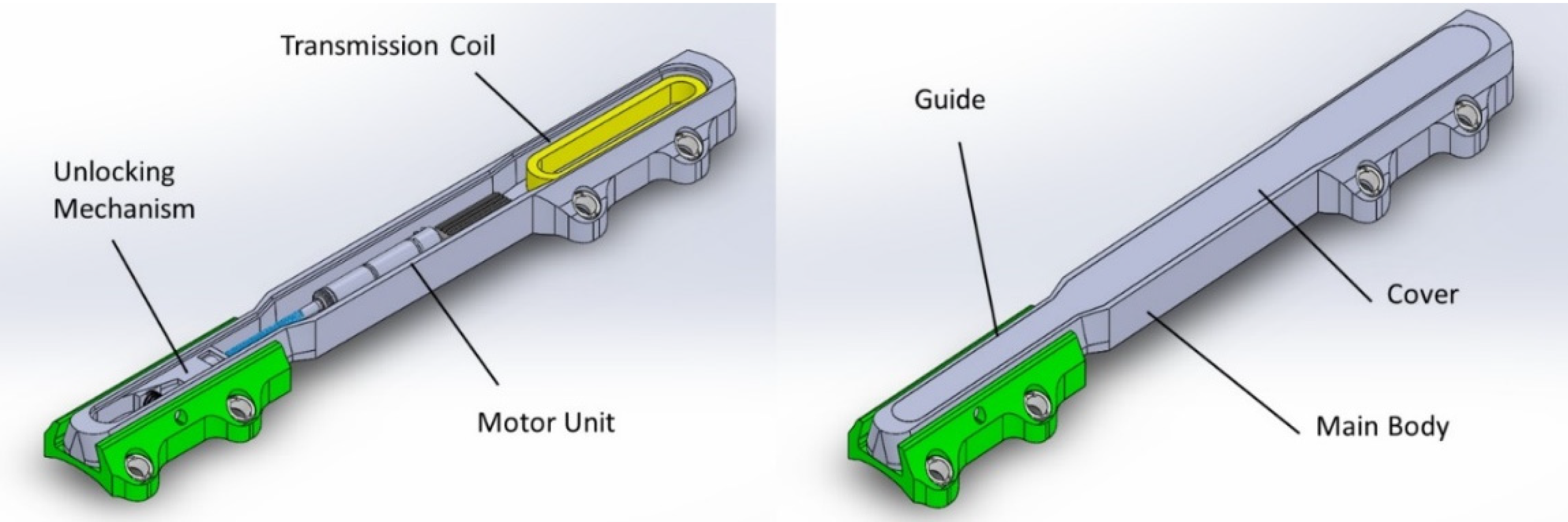
These considerations have led to the following conceptual design (Figure 1):
  • The two parts (the ‘body’ and the ‘guide’) are coupled through a dove-tail prismatic guide in order to allow the axial translation and prevent both flexion and torsion;
  • In the ‘locked’ configuration, the axial translation is blocked through a pin, pre-loaded by a spring and supported, inferiorly, by an inclined plane;
  • In the ‘unlocked’ configuration, the lower support of the pin lowers due to a horizontal translation of the inclined plane, provided by the actuator; the pin is so disengaged by the pre-loaded spring.
All plate components were made with AISI 316LVM steel, which is a standard material usually adopted for biomedical implants manufacturing.
In the following, details concerning the multibody analysis, the stress analysis, experimental test and manufacturing flow were reported.

2.1. Multibody Analysis

The design optimization of the locking mechanism between the guide and the body was performed through a multibody parametric model created with ADAMS View (2019, MSC Software, Santa Ana, CA, USA).
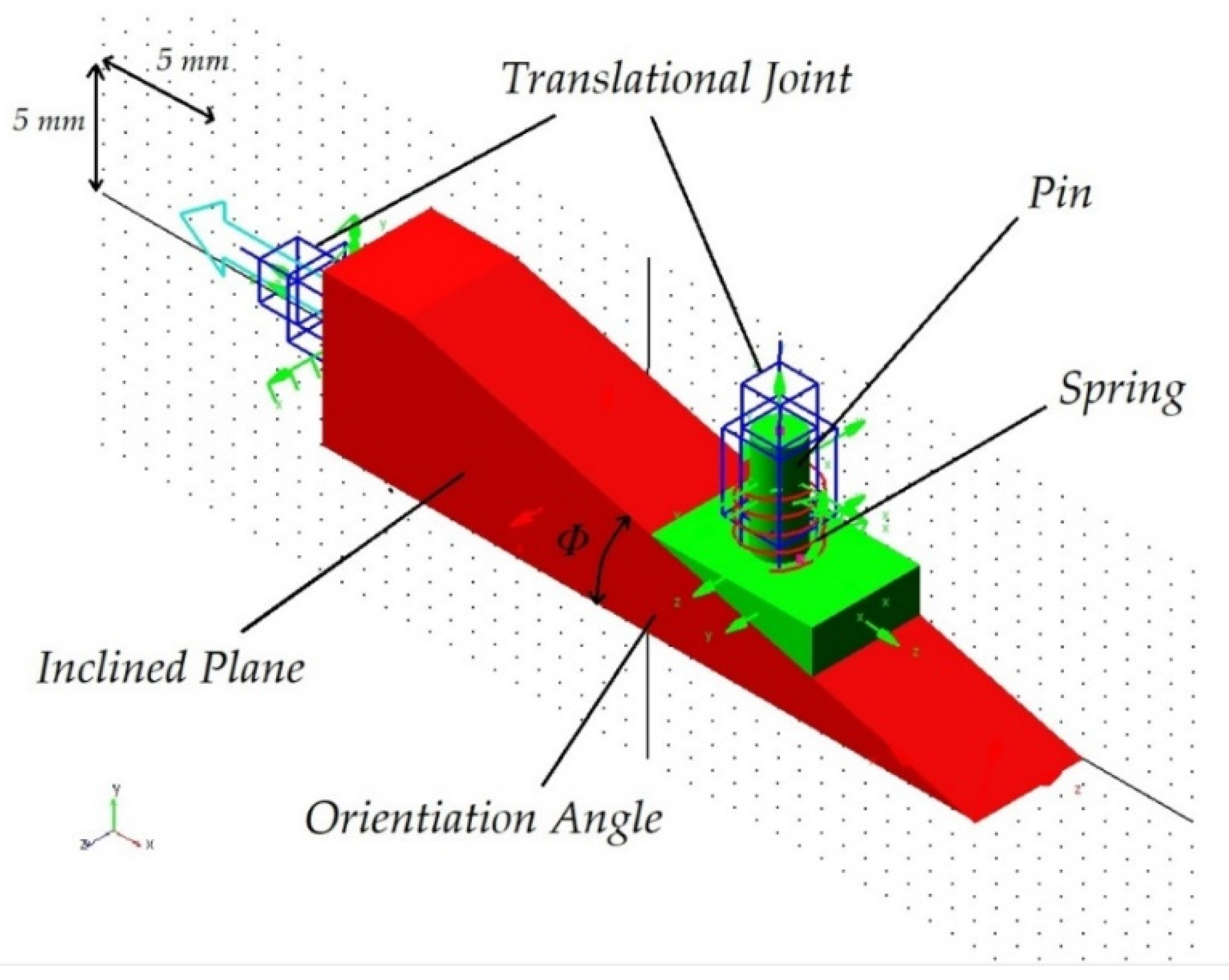
According to the conceptual design described above, some key components are identified and parameterized: the inclined plane, whose sliding gives room to the vertical translation of the pin; the pin which can slide vertically, blocking or unblocking the axial sliding between guide and main body; the spring preloading the pin and keeping its head in contact with the inclined plane. The key design parameters playing a major role on the lock/unlock mechanism are therefore:
  • Friction coefficients between the inclined plane and the pin head, between the inclined plane and the main body, and between the pin and its housing;
  • The stiffness and the preload of the spring;
  • The angle of inclination of the sliding plane.
The required spring pre-load can be minimised through an adequate inclination of the plane; this same condition would guarantee the reversibility of the motus (blocking action) in case the pin should return to its housing, as a consequence of a horizontal force, pushing the inclined plane.
The multibody model (Figure 2) was created reproducing some main geometries inside the software, where the inclination of the plane (Φ) and of the congruent pin head were parameterised with the respective inclination angle, ranging between 9° and 18° by steps of 3° and varying the coefficient of friction between 0.15 and 0.60 by a step of 0.15: this minimum value is represented by the coefficient of friction between AISI 316LVM and polyethylene with the presence of serum lubricant [15]. The only two contact surfaces were simulated, with the boundary conditions reported in the following:
  • The pin is free to translate vertically, with a given friction;
  • The inclined plane is free to translate horizontally with respect to the main body, with a given friction;
  • The contact between the main body and the guide were modelled by means of an impact formulation, where a high contact stiffness value was assigned considering that both parts are made of metal (stiffness k = 100,000 N/mm, damping c = 10 Ns/mm).
  • The inclined plane was forced to move horizontally, with a sinusoidal waveform x = 5 sin(2π/12 t) in order to reproduce both the release and the subsequent lock in 6 s.
The action of the spring element was tuned having parameterised its preload, which ranges between 20 N and 80 N. The range of variation of the main parameters concerning the multibody model are reported in Table 1, in which the two main output are represented by both the maximum force and power required to push and pull the specific unlocking mechanism. Specifically, the power was calculated as follows, in which F is the locking/unlocking force and v is the horizontal translation speed:
P   =   F · v
It was important to evaluate the power because it represent the key specification to choose the specific direct current (DC) motor to be used to move the mechanism.
To conclude, the static coefficient of friction was considered rather than dynamic coefficient of friction in order to reach the most conservative estimation.

2.2. Stress Analysis

The stress analysis was performed through a finite element model (FEM), of a more refined design (Figure 3), taken from an existing plate [16]. This is composed of several parts which can interact with each other in the following way: (1) the central body can slide along its guide in the unlocked configuration (with the pin retracted into the main body); (2) the pin can slide along its housing, thanks to the retraction of the inclined plane which is connected directly to the motor unit; (3) the cover and the main body are welded together in order to avoid any liquid leakage inside the main chamber.
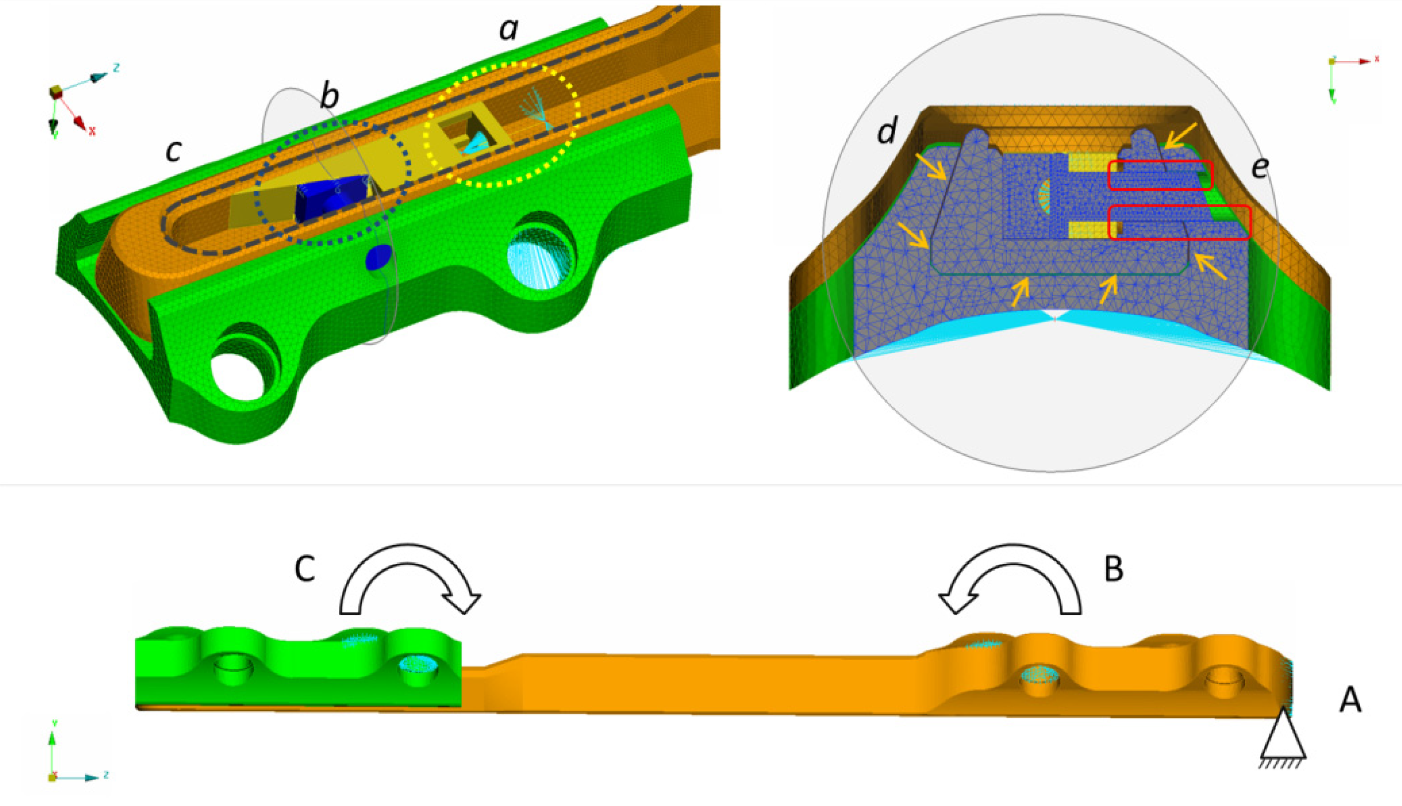
Two different FE models were developed in order to accomplish the whole static and dynamic performance of the plate. Both models were simulated with Abaqus CAE (2017, Dassault Systemes, Vélizy-Villacoublay, FR) and were finalized to estimate the fatigue bending strength and the ultimate static load of the actual plate, with reference to the ASTM F382 regulation. In particular, the first FE model (FE1 in the following) was built up with the only plate, which was specifically constrained in order to reproduce the maximum bending moment deriving from the four-point bending test prescribed by the same regulation. Following this simplified setup, one end of the dynamic fixator was fully constrained (Figure 4, point A), while an opposite reaction equal to 29 Nm was applied at two central point corresponding to the middle central body screws and guide screws (Figure 4, points B and C). This flexural moment was taken from the fatigue limit of a static plate produced by the same company, subjected to a pulsating, constant amplitude load (R = 0.1; with R being the ratio between the minimum and maximum load), in order to be able to compare the respective performance [16]. In addition, a second FE model (FE2 in the following) representing the full experimental setup was implemented in order to evaluate the static strength of the whole bone-plate system (Figure 5).
The two models were prepared in order to obtain a fine discretization of the initial solid geometry: the final mesh was made of “tetra 4” elements with an internal “grow rate” of 1.2, which is a good compromise between the overall refinement and the computational cost of the simulation [17,18,19]. The final element size ranged between 0.2 to 0.8 mm considering all plate components (Table 2, Figure 4), while a larger size was selected for the bone and the rollers (Table 2, Figure 5). All reciprocal interactions were modelled with a standard “pressure-overclosure” formulation, and a specific exponential behaviour with a given friction. Looking at the main contacts inside the model, it is important to highlight all the following features concerning internal plate components: (1) the inclined plane was constrained to the main body next to the motor unit in order to avoid any reciprocal sliding between these two parts, as happens in the real component (Figure 4, detail a); (2) the pin can slide into its seat, but is constrained with six low-stiffness axial springs, located along its border in order to prevent initial lability inside the model (Figure 4, detail b); (3) the central body and the cover were constrained along their borders with a rigid “tie” constraint, in order to effectively reproduce the structural continuity provided by metal welding (Figure 4, detail c); (4) the gap between the guide and the central body was equal to 0.1 mm along its main borders (Figure 4, detail d), while the gap between the pin and its housing was set equal to 0.05 mm (Figure 4, detail e), according to plate design.
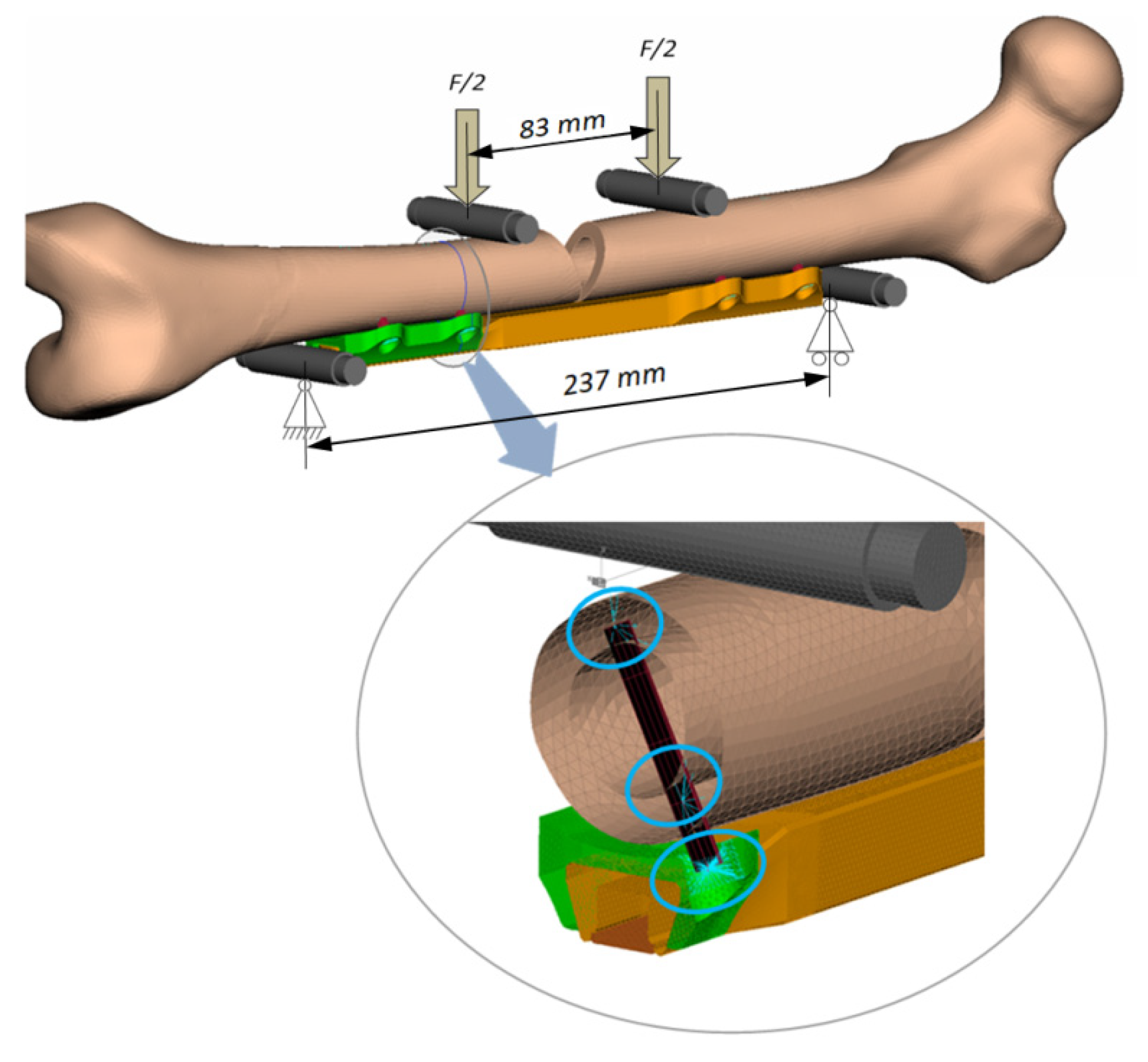
Considering the full experimental setup detailed in Figure 5, the following components were modelled and integrated inside the previous model (FE1 model):
  • A standard femur (Sawbones®, Europe AB, Malmoe, Sweden), whose geometry was modified in order to reproduce a central fracture with the classical “V shape” cutting having 20 mm base;
  • Four metallic rollers were modelled and positioned in order to reproduce the exact loading setup of the four-point bending test (prescribed by ASTM F382 regulation);
  • The plate–bone connections were modelled with rigid kinematic joints (RBE2) connected to each other with specific flexible elements (circular beams whose minimum section has a diameter equal to 3.5 mm) in order to reproduce the screws contribution inside the model.
For all plate components the AISI 316LVM steel was assigned as constitutive material, having an elastic modulus equal to 187.5 GPa and a Poisson’s ratio equal to 0.3, and considering a linear and isotropic behavior; the respective non-structural Sawbones® (0.6 GPa of elastic modulus and 0.3 of Poisson’s ratio) was assigned to the bone, and a standard Stainless steel (210 GPa of elastic modulus and 0.3 of Poisson’s ratio) to the beams and the rollers. Due to the multiple contacts involved, a static non-linear simulation was carried out with an initial step size of 0.01.

2.3. Experimental Tests

The experimental test was carried out with the Instron Electropuls E3000, an axial-torsional machine capable of delivering up to 3000 N of axial load and up to 25 Nm of torque. According to the most recent calibration, the axial load cell has a resolution equal to 0.001 N and a repeatability below 0.124%. ASTM F382 regulation (the gold standard for osteosynthesis devices) prescribes carrying out a four-point bending test in order to identify the bending stiffness and the bending strength of the device. In this particular case, the unusual shape of the bone plate, which has no holes along the main body, requires the adaptation of the standard prescriptions in order to solicit the critical portion of the device. In order to evaluate the bone plate in a realistic configuration, a femur anatomical replica (Sawbones®, Europe AB, Malmoe, Sweden) was used as extension for the loads application. Two conditions were tested: (1) the bone plate mounted on an integer femur and (2) the bone plate mounted on a fractured femur (B2 diaphyseal fracture from AO/OTA classification). The integer sample was used to simulate the bone behaviour when an ‘ideal’ healing process has terminated.
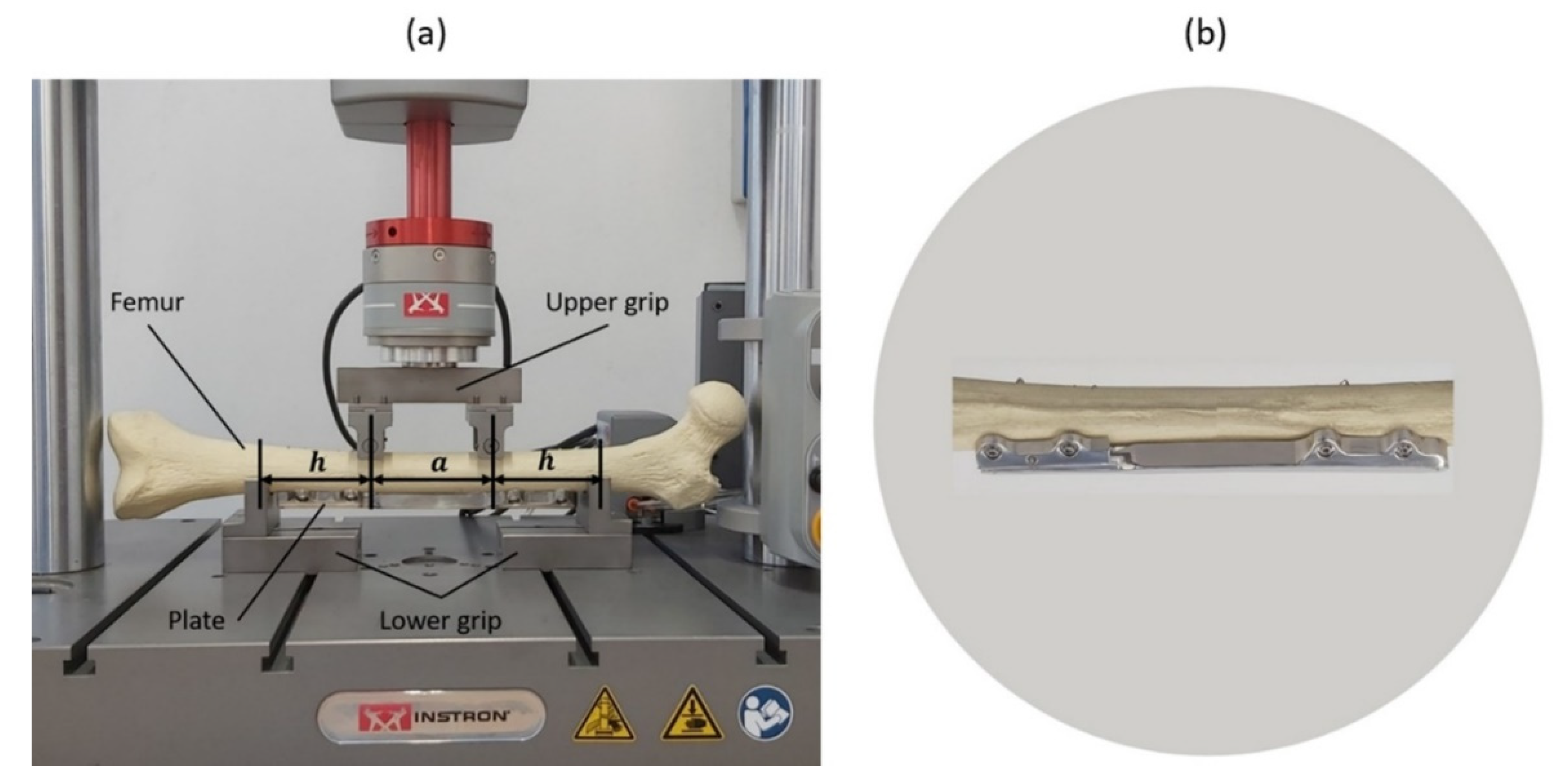
The testing machine was equipped (Figure 6) as follows:
  • The upper grip bears two rollers, whose distance was set equal to ‘a’ (83 mm);
  • The lower grip bears two supports, whose distance is equal to ‘2 h + a’ (237 mm).
Experimental tests were displacement controlled at a rate equal to 5 mm/min. Flexural stiffness was calculated from the force-displacement curve, as the slope of its initial linear portion, according to ASTM F382 regulation. The output data were checked against the similar static fixation device whose stiffness was equal to 253 N/mm and whose bending moment at failure was equal to 79 kN mm [16].

2.4. Manufacturing Flow

The first prototypes were built, according to the European Regulation 2017/745 for medical devices, and the whole workflow was established by a manufacturing company holding ISO 13485:2016 certification.

3. Results and Discussion

3.1. Output of the Multibody Model

Findings have confirmed the relevant role of the coefficient of friction on the system performance and revealed a linear (R2 = 0.99) relationship between this coefficient and the maximum required power. For sake of clarity, since the main objective of the multibody analysis was to minimize the aforementioned power, only the case involving the lowest coefficient of friction of 0.15 is reported in the following.
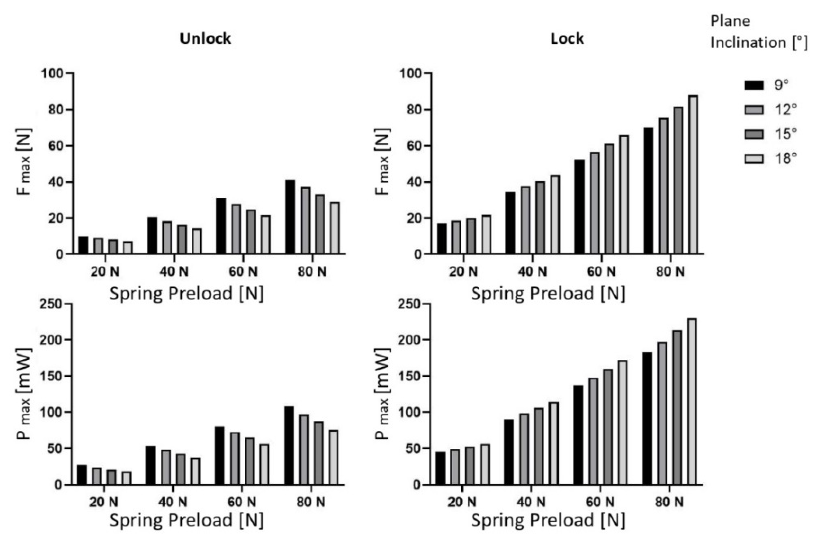
The main outputs of the multibody model are reported in Figure 7: the higher the inclination, the smaller the unlocking force, and the higher the locking force; the higher the spring pre-load, the higher the unlocking and locking forces. On the whole, the minimization of the unlocking power that is the main objective of this analysis would require a higher plane inclination (18°) and a minimum spring pre-load (20 N), able to guarantee pin motion, overcoming friction forces between the pin and the respective hole. In the last conditions, the required power to unlock the plate is equal to 18 mW, while re-locking would require above 50 mW; as such, this possibility was discarded for the time being, which meant that the plate could be dynamized, but it could not revert to its locked configuration even if the required force would fall within specifications (20 N).

3.2. Output of the Finite Element Model

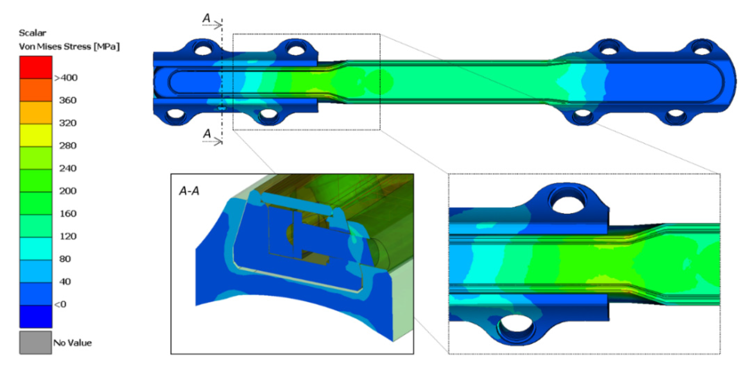
The more interesting result concerning the stress analysis is reported in Figure 8 where the plate and its internal components were analyzed (FE1 model). The peak von Mises stress is reached in a very localized zone and is equal to 340 MPa; this would correspond to an average stress equal to 187 MPa and a stress amplitude equal to 153 MPa considering an R = 0.1 factor for the fatigue test. According to data reported by the producer, the stress amplitude limit of the plate constitutive material is equal to 400 MPa for R = −1 (fully reversed loading), its ultimate load is equal to 920 MPa, and its yield stress is equal to 800 MPa [20]; this results in a stress amplitude limit equal to 261 MPa for R = 0.1, according to the Haigh diagram for fatigue strength. In conclusion, the safety factor of the plate resulted in being equal to 1.70 (261/153), which is an acceptable value according to ASTM F382.
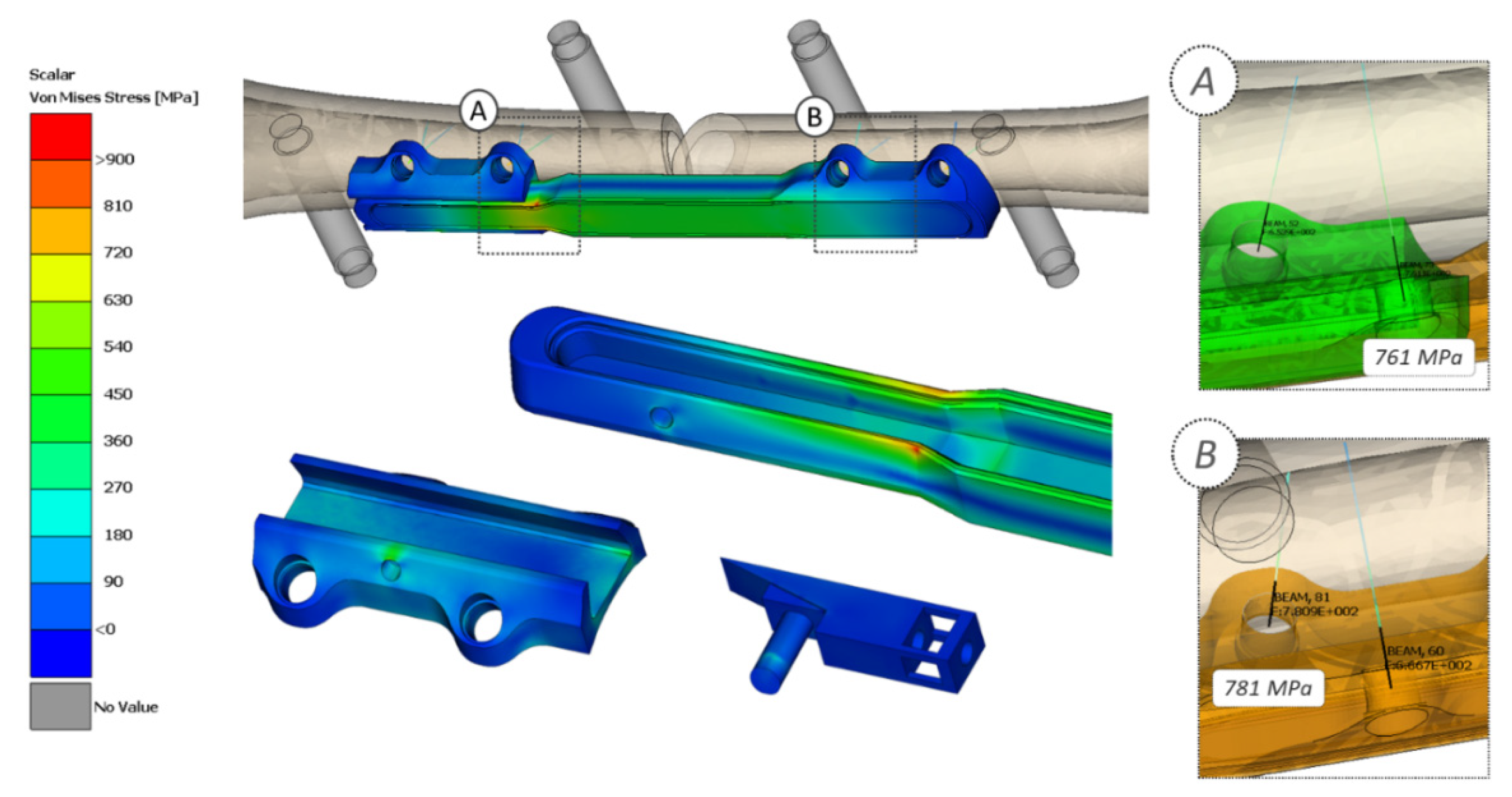
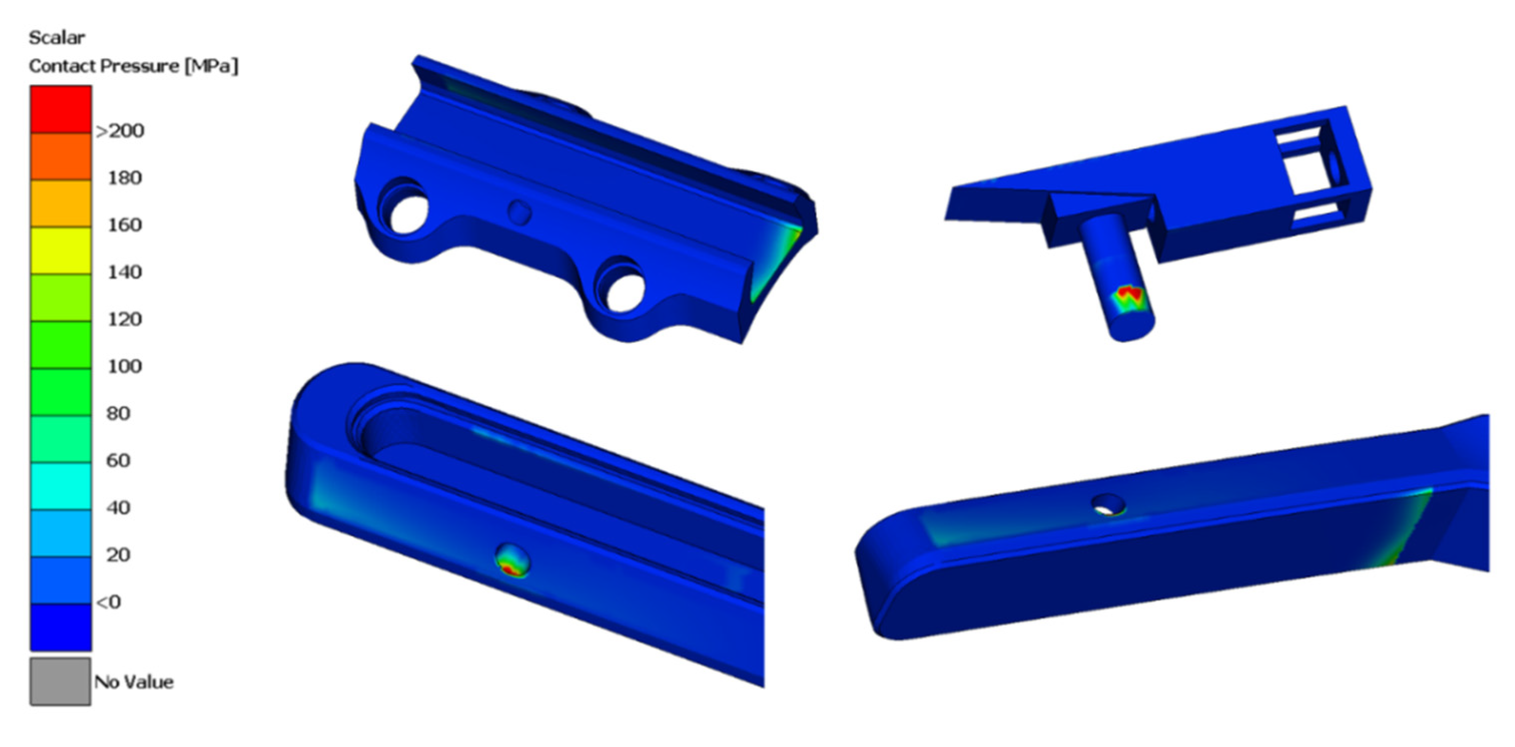
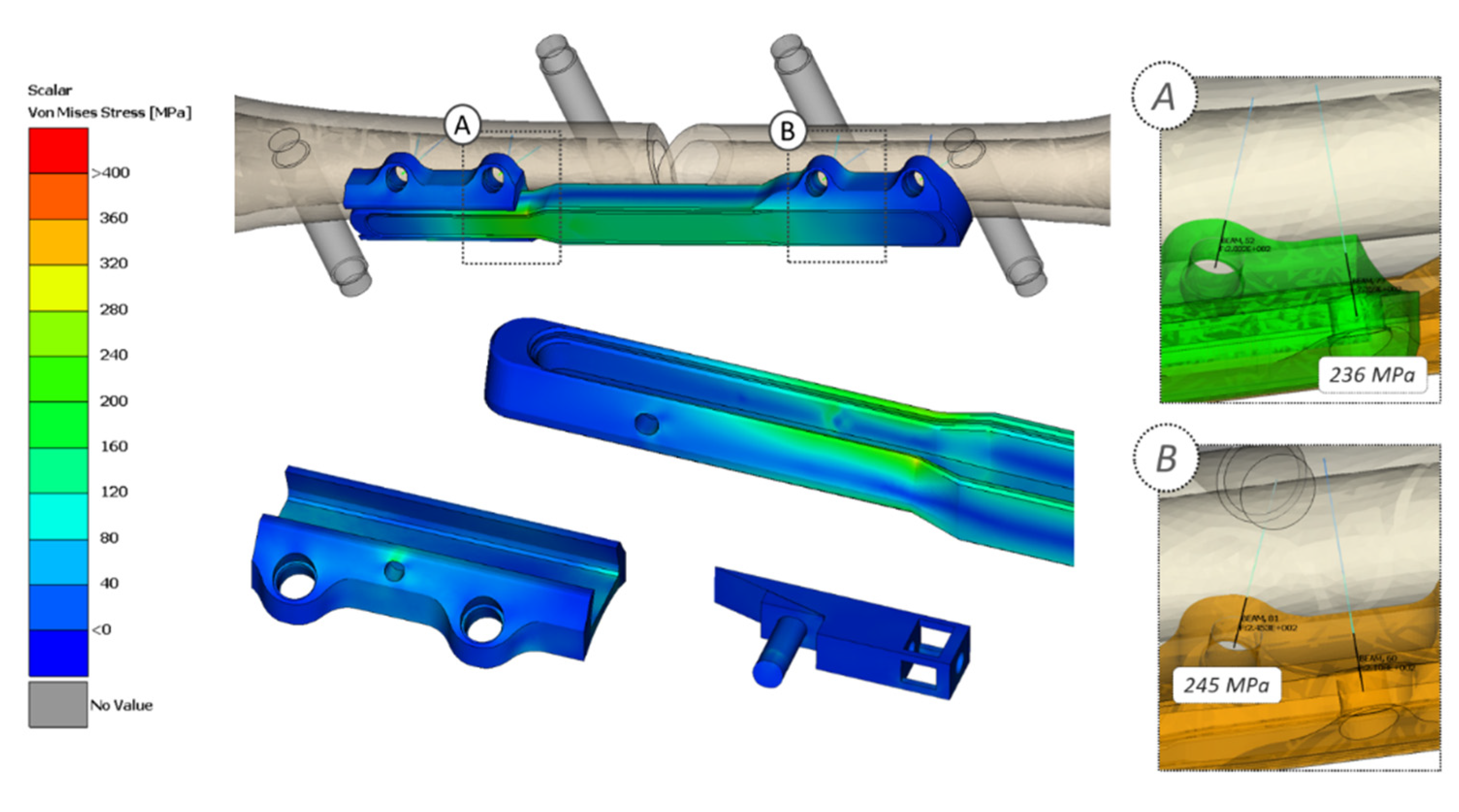
In addition, it should be noted how a very unfavorable estimation is being performed: the peak load is reached in a very localized area at a taper of the main body section; as such, it would result in local plasticization which finally would provide a residual stress opposite to the applied stress (considering that fatigue stress is performed with a pulsating stress, as required by orthopedic plate certification). These results are confirmed also by the FE2 model, in which the maximum static load was simulated according to experimental test. Both von Mises stresses and the maximum contact pressure testify that the plate is safe in terms of static strength; the most stressed point in terms of static strength remains the same, as considered in the FE1 model, with a maximum stress equal to 923 MPa (Figure 9), while a maximum contact pressure of 376 MPa is localized at the most stressed area of the pin (Figure 10). In addition, considering the 33% of the maximum load, which would correspond to a bending moment equal about to 25.3 Nm, the peak stress is equal to 299 MPa (Figure 11), confirming a good approximation obtained with the simplified setup (FE1 model).

3.3. Experimental Tests

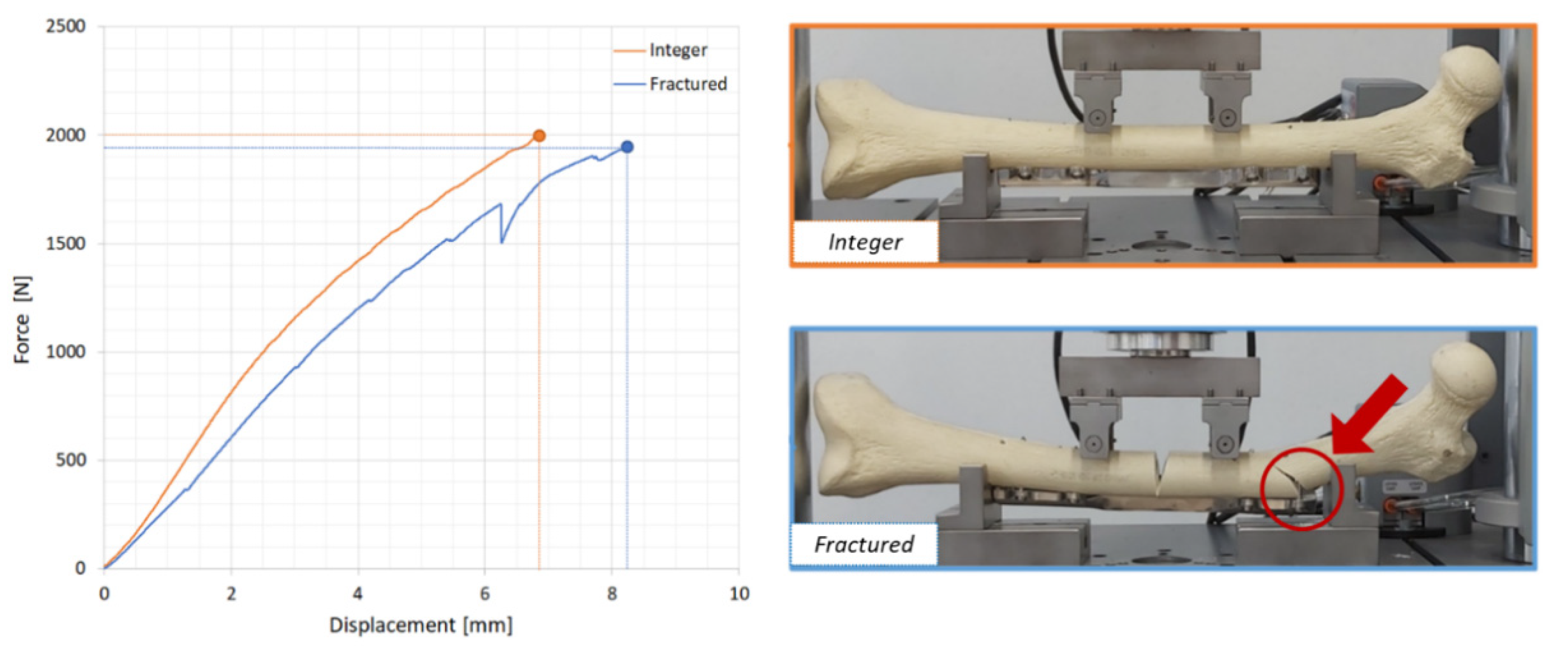
Figure 12 shows the output of the experimental tests performed on the integer (orange curve) and on the fractured (blue curve) samples. As a consequence of the healing process, the secant stiffness of the bone/plate system can improve up to 20.2%. According to experimental tests, the integer sample sustained the load up to 2000 N without damage (the test stopped at 2000 N to prevent prototype failures), while the fractured one failed at 1957 N: the plate remained intact, but the bone broke, in fact a second fracture was indeed visible in proximity of the right lower support. Taking as reference this second result, which was more comparable with an ASTM F382 standard four-point bending test, the peak load was 18% lower than 2400 N, measured for the reference static plate, but it was estimated to be satisfactory, considering the performance of other orthopaedic plates on the market [16]. With reference to finite elements results reported in the previous paragraph, it should be noted how the maximum bending moment from experimental tests has resulted in being equal to 75.3 Nm (obtained by multiplying half load, 978.5 N by its arm equal to 77 mm) which is far beyond 29 Nm applied in the finite element model to compare its results to other obtained for a similar non-dynamizable plate; in addition, even 75.3 Nm did not produced failure of the plate or any of its components in static experimental tests, confirming findings from numerical FE analysis. The same experimental tests allowed us to calculate the bending stiffness of this plate which resulted in being equal to 370 N/mm, that is +46% compared to the static reference plate. Experimental error could not be evaluated since one single specimen was considered; however, similar tests on the reference plate resulted in a 5% variability of results.

3.4. Manufacturing Flow

Once the component was designed in detail, the respective manufacturing flow had to be set up, according to the Medical Device Regulation (EU) 2017/745 for medical devices. Its main steps were:
  • Step 1: Sourcing of raw materials;
  • Step 2: Machine processing: folding, milling, drilling, threading, wire erosion; roughing, burr removal; washing; packaging in labelled bags;
  • Step 3: Acceptance check;
  • Step 4: Acceptance; belt sanding; polishing; washing; final check; packaging, shipping;
  • Step 5: Solvent washing; sandblasting; quality control (QC), single packaging in plastic trays;
  • Step 6: Acceptance check;
  • Step 7: Marking; washing; preliminary packaging (Clean Room ISO 7 Operational);
  • Step 8: Sterilization;
  • Step 9: Acceptance check;
  • Step 10: Final packaging and labelling; release.
At this stage, experimental and numerical tests demonstrated that the new dynamizable plate behaved adequately from a mechanical point of view compared to other devices already on the market. Ongoing tests are focusing on the evaluation of the locking/unlocking mechanism, as well as on the transmission system design. To allow marketing of the plate, the preliminary analysis presented here will be followed by a rigorous campaign of mechanical tests on a number of replicas able to ensure statistical consistency. According to ASTM F382, both static and fatigue testing will be performed and a rationale will be built for the device certification request to the notified body.

4. Conclusions

A new dynamizable plate for fracture synthesis was designed and tested in order to define its global structural strength according to current medical device regulations. Its main peculiarity is that it allows a non-invasive dynamization to be performed in the post-operative period, to shorten healing times and enhance the quality of the new formed bone. A careful parametric study of the locking/unlocking mechanism was carried out through a detailed multibody model, where the main variables were outlined in order to minimize global power consumption. A detailed FE model was set up in order to evaluate the fatigue strength of the component according to ASTM F382 regulation, confirming its good performance compared to a reference plate already on the market. Experimental tests were carried out in order to evaluate the maximum strength of the whole bone-plate system, in terms of flexural strength and maximum bending moment and a complete FE model was developed in order to check by means of maximum stress the global structural strength of the same bone-plate system.

Author Contributions

Conceptualization, M.T., A.L.A., P.C. and G.D.; methodology, all authors; validation, M.T., G.P. and M.C.; formal analysis, G.D., G.P. and M.T.; investigation M.T., G.P., G.D. and A.L.A.; resources, M.T., P.C. and A.L.A.; data curation, G.D. and M.C.; writing—original draft preparation, E.M.Z., M.C. and G.D.; writing—review and editing, all authors; supervision, P.C. and A.L.A.; project administration, M.T., G.D. and P.C.; funding acquisition, A.L.A. and P.C. All authors have read and agreed to the published version of the manuscript.

Funding

The project was funded by W.D.Plate—P.O.R. FESR 2014-2020 Piemonte—“Poli Innovazione Linea A”.

Conflicts of Interest

There is no conflict of interest. Author Piero Costa works for Intrauma Spa Company, producing orthopaedic plates.

References

  1. Mujtaba, A. Characteristics on fractures of tibia and fibula in car impacts to pedestrians and bicyclists—Influences of car bumper height and shape. Annu. Proc. Assoc. Adv. Automot. Med. 2007, 67, 14–21. [Google Scholar]
  2. Gulati, D.; Aggarwal, A.N.; Kumar, S.; Agarwal, A. Skeletal injuries following unintentional fall from height. Turk. J. Trauma Emerg. Surg. 2012, 18, 141–146. [Google Scholar] [CrossRef] [PubMed]
  3. Axelrod, T.; McMurtry, R. Open reduction and internal fixation of comminuted, intraarticular fractures of the distal radius. J. Hand Surg. 1990, 15, 1–11. [Google Scholar] [CrossRef]
  4. Terzini, M.; Mossa, L.; Bignardi, C.; Costa, P.; Audenino, A.L.; Vezzoni, A.; Zanetti, E.M. A structural numerical model for the optimization of double pelvic osteotomy in the early treatment of canine hip dysplasia. Veter. Comp. Orthop. Traumatol. 2017, 30, 256–264. [Google Scholar] [CrossRef] [PubMed] [Green Version]
  5. Pascoletti, G.; Cianetti, F.; Putame, G.; Terzini, M.; Zanetti, E.M. Numerical simulation of an intramedullary elastic nail: Expansion phase and load-bearing behavior. Front. Bioeng. Biotechnol. 2018, 6, 1–11. [Google Scholar] [CrossRef] [PubMed] [Green Version]
  6. Sonderegger, J.; Grob, K.R.; Kuster, M.S. Dynamic plate osteosynthesis for fracture stabilization: How to do it. Orthop. Rev. 2010, 2, 4. [Google Scholar] [CrossRef] [PubMed] [Green Version]
  7. Henschel, J.; Tsai, S.; Fitzpatrick, D.C.; Marsh, J.L.; Madey, S.M.; Bottlang, M. Comparison of 4 methods for dynamization of locking plates. J. Orthop. Trauma 2017, 31, 531–537. [Google Scholar] [CrossRef] [PubMed] [Green Version]
  8. Bottlang, M.; Tsai, S.; Bliven, E.K.; Von Rechenberg, B.; Klein, K.; Augat, P.; Henschel, J.; Fitzpatrick, D.C.; Madey, S.M. Dynamic stabilization with active locking plates delivers faster, stronger, and more symmetric fracture-healing. J. Bone Jt. Surg. Am. Vol. 2016, 98, 466–474. [Google Scholar] [CrossRef] [Green Version]
  9. Claes, L.; Wilke, H.J.; Augat, P.; Rübenacker, S.; Margevicius, K. Effect of dynamization on gap healing of diaphyseal fractures under external fixation. Clin. Biomech. 1995, 10, 227–234. [Google Scholar] [CrossRef]
  10. Larsson, S.; Kim, W.; Caja, V.L.; Egger, E.L.; Inoue, N.; Chao, E.Y. Effect of early axial dynamization on tibial bone healing. Clin. Orthop. Relat. Res. 2001, 388, 240–251. [Google Scholar] [CrossRef] [PubMed]
  11. Yamaji, T.; Ando, K.; Wolf, S.; Augat, P.; Claes, L. The effect of micromovement on callus formation. J. Orthop. Sci. 2001, 6, 571–575. [Google Scholar] [CrossRef] [PubMed]
  12. Foxworthy, M.; Pringle, R. Dynamization timing and its effect on bone healing when using the orthofix dynamic axial fixator. Injury 1995, 26, 117–119. [Google Scholar] [CrossRef]
  13. Yaneva-Deliverska, M.; Deliversky, J.; Lyapina, M. Biocompatibility of medical devices—Legal regulations in the European Union. J. IMAB Annu. Proc. 2015, 21, 705–708. [Google Scholar] [CrossRef] [Green Version]
  14. Zyga, S. Application of ISO 13485:2003 in biomedical engineering: A systematic review. Int. J. Caring Sci. 2011, 4, 58–65. [Google Scholar]
  15. El-Domiaty, A.; El-Fadaly, M.; Nassef, A.E. Wear characteristics of ultrahigh molecular weight polyethylene (UHMWPE). J. Mater. Eng. Perform. 2002, 11, 577–583. [Google Scholar] [CrossRef]
  16. Terzini, M.; Serino, G.; Lugas, T.A.; Dichio, G.; Costa, P.; Audenino, A.L. Strategies to Speed up the Standardized Bone Plates Mechanical Testing for Regulatory Purposes; Pedrizetti, G., Accardo, A., Marceglia, S., Brun, F., Eds.; 2020; Available online: https://portal.issn.org/resource/ISSN/2724-2129 (accessed on 29 September 2020).
  17. Zanetti, E.M.; Ciaramella, S.; Calì, M.; Pascoletti, G.; Martorelli, M.; Asero, R.; Watts, D.C. Modal analysis for implant stability assessment: Sensitivity of this methodology for different implant designs. Dent. Mater. 2018, 34, 1235–1245. [Google Scholar] [CrossRef] [PubMed] [Green Version]
  18. Pascoletti, G.; Calì, M.; Bignardi, C.; Conti, P.; Zanetti, E.M. Mandible morphing through principal components analysis. In International Conference on Design, Simulation, Manufacturing: The Innovation Exchange; Springer: Cham, Switzerland, 2019; pp. 15–23. [Google Scholar]
  19. Ambu, R.; Motta, A.; Calì, M. Design of a customized neck orthosis for FDM manufacturing with a new sustainable bio-composite. In International Conference on Design, Simulation, Manufacturing: The Innovation Exchange; Springer: Cham, Switzerland, 2019; pp. 707–718. [Google Scholar]
  20. L. KLEIN SA. AISI 316 LVM Implant: Materials and Raw Manufacturing Data. Available online: http://www.kleinmetals.ch/steel/316-lvm-f-138-implants.htm (accessed on 10 August 2020).
Figure 1. Conceptual design of the plate dynamization system.
Applsci 10 06844 g001
Figure 2. Multibody model of the pin unlocking mechanism.
Applsci 10 06844 g002
Figure 3. Refined design of the plate: detail of internal and external components.
Applsci 10 06844 g003
Figure 4. Upper Image—detail of mesh and connections: (a) connection between inclined plane and main body; (b) connection between the pin and the inclined plane; (c) connection between the main body and the cover (not represented in the image); (de) details of the gap between main body and guide and between the pin and its housing; Lower image—detail of applied loads: (point A) full lateral constraint (6 DOF: Degrees Of Freedom); (point BC) opposite bending moment applied at the master nodes of the two rigid kinematic joints (RBE2).
Applsci 10 06844 g004
Figure 5. FE2 model with respective loads and boundary constraints; detail of one screw modelling section.
Applsci 10 06844 g005
Figure 6. Four point bending test with Instron Electropulse E3000: (a) loading set up; (b) plate detail.
Applsci 10 06844 g006
Figure 7. Main results of multibody model (friction coefficient: 0.15, spring stiffness: 20 N/mm).
Applsci 10 06844 g007
Figure 8. Maximum von Mises stress at the referenced fatigue bending limit (29 Nm): detail of plate components.
Applsci 10 06844 g008
Figure 9. Maximum von Mises stress at the experimental peak static load (2 kN): detail of plate components and more stressed screws (A and B boxes).
Applsci 10 06844 g009
Figure 10. Maximum contact pressure at the experimental peak static load (2 kN): detail of plate components.
Applsci 10 06844 g010
Figure 11. Maximum von Mises stress at 33% of experimental peak static load (660 N): detail of plate components and more stressed screws (A and B boxes).
Applsci 10 06844 g011
Figure 12. Force-displacement curves obtained from the experimental tests for integer and fractured samples: the red arrows mark the point where the femur broke.
Applsci 10 06844 g012
Table 1. Details of multibody model variables.
VariableValue
INPUT DATAPlane Inclination (°)9°–18°
Friction Coefficient0.15–0.60
Spring Pre-load (N)20–80
Spring Stiffness (N/mm)20
Input Displacement (mm)5 sin(2π/12 t)
OUTPUT DATAForce Maximum (N)
Power Required (mW)
Table 2. Details about finite element mesh of the whole bone-plate system.
ComponentElement TypeNumber of ElementsElement Size (mm)Material Type
Main Body3D Tetra4415,4560.3–0.8AISI 316LVM
Guide3D Tetra4134,4100.3–0.8AISI 316LVM
Cover3D Tetra4267,5820.4–0.5AISI 316LVM
Pin3D Tetra446,1470.2–0.3AISI 316LVM
Inclined Plane3D Tetra433,2090.4–0.5AISI 316LVM
Bone3D Tetra4230,3961.8–2.2Sawbones®
Rollers2D Shell 21,3360.8–1.2Stainless steel
Screws1D Beam 4 × 87 × 3.5Stainless steel
Total n° of Elements:1,148,568