1. Introduction
Additive manufacturing, often referred to as 3D printing, is defined according to ISO TC 261 norm as a process in which material is joined in thin layers based on data from 3D models created via Computer Aided Design (CAD) system to manufacture the final parts [
1]. Additive manufacturing includes a number of devices which differ from each other mainly in the type of material to be joined and the method of how the given material is joined, i.e., the energy source. The relative freedom in the design itself being incomparable to the conventional manufacturing methods is one of the main advantages of opting for additive manufacturing. All of the stated provide new opportunities in the development and the subsequent manufacturing of prototypes, the testing of functional samples, the application of new possibilities for modelling and manufacturing complex geometries and structures, and the related weight and cost reduction [
2].
The utilization of additive manufacturing technologies also involves certain limitations, such as acquisition cost for equipment and materials, slow manufacture, and low quality and precision, with the need for further work to achieve the final desired shape and finish. It can be assumed that certain mentioned factors will be eliminated or minimized due to the recent rapid development of the additive technologies. Regardless of the above-mentioned limitations, additive manufacturing technologies are already widely present in industrial practice, and thus, in terms of manufacturing, they are already viable for certain utilization even today [
3].
Such utilization includes the manufacture of moulds or parts with complex shapes. One of the advantages of additive manufacturing in the mould construction process is the manufacture of conformal cooling in which the cooling channels copy the shaped part of the mould, unlike the drilled cooling system. The conformal cooling ensures a smoother temperature distribution in the mould cavity and also reduces residual stresses in the moulding or casting. The side effect is consequent time reduction in manufacturing cycle, since the need of an additional mould cavity cooling is reduced and the manufactured part is thus more quickly demoulded [
4].
There are specific problems arising from the DMLS technology utilization in the manufacturing process. One of these problems is the creation of residual stresses during the sintering process. Cracks and fractures, which result in geometrical inaccuracies of the manufactured part, can occur particularly on the edges of the manufactured model due to the stress effects. A dangerous situation occurs when the manufactured part is being completely torn off from the platform of the machine and a collision between the manufactured part and the moving parts of the machine occurs, thus causing damaged. The moving part of the machine is a ceramic knife that evenly applies the powder material prior to sintering of each layer. A collision between this part and the knife occurs when an already created part of the model is torn off and moved in the direction of the
z-axis [
5].
Lin Cheng and colleagues used a voxel-based methodology in their research of model orientation optimization in order to achieve residual stress reduction. The main focus of the work is the achievement of a reduction of residual stresses and overall material consumption. When variants of components with and without optimization were compared, the results showed a reduction in residual stresses as well as a reduction in material consumption and production time [
6,
7].
A study by Chimmat et al. experimentally investigates residual stresses in the DMLS process in steels by X-ray diffraction. The process parameter for the sample was optimized for the highest possible model density (≥99.95%). The determined magnitudes of the residual stresses were subsequently compared with the values after the heat treatment. They concluded that additional heat treatment has a positive effect on residual stresses, hence it almost completely eliminates them [
8].
Ghasri-Khouzani and colleagues dealt with the issue of residual stresses in disc parts manufactured from steel via the DMLS technology, hence neutron diffraction was used to profile residual stresses and the coordinate system was used to measure the CMM parts. They concluded that the magnitude of residual stresses decreased rapidly after removing the part from the mother board and removing the auxiliary structures as well [
9].
Kemerling and colleagues focused their study on describing the magnitude of residual stresses as a function of manufacturing process parameters. They considered the sintering strategy itself, as well as the chamber preheating temperature, as the key parameters. The finite element method was used for the process simulation, and the neutron diffraction was used for the experimental measurements. Hence, there was a high degree of agreement between the calculated and experimental results. Their study showed that the sintering strategy has a major impact on the magnitude of created residual stresses [
10].
The study by Panda and Sahoo provides insights into the creation of the complex thermo-mechanical model in order to study the cyclically repetitive thermal load and resulting residual stresses in the DMLS process. They used the finite element method for the calculation model of the analytical solution. The sintering speed and the used laser power were the parameters observed in their study. Their findings show that the repeated thermal expansion and contractions arising from the powder bed are responsible for the residual stress creation [
11].
Leuders and colleagues studied the cracking resistance from residual stresses and came to the conclusion that residual stresses are cumulated on the edges of the manufactured model; however, they are significantly higher in the manufacturing direction than in the vertical direction [
12].
The issue of the creation and reduction of residual stresses in the parts manufactured via the DMLS technology is still relevant, thus it is the topic of this paper with the places in which the stress is created and its maxima being the main focus of the study. Hence, the study proposes alternative solutions to the monolithic model via the optimization of the internal structures. The mechanical properties, namely maintaining the functionality and durability of the manufactured part, which is a shaped insert for the plastic injection, were taken into account. The reduction of the manufacturing time and material saving subsequently reducing the cost of production itself can be considered as benefits associated with the alternative solutions [
13].
3. Internal Stress in the Component Parts Manufactured via the DMLS Technology
According to the American patent, the DMLS technology represents a method of fusion process of powder base in which a thin layer of metal powder is without any other binding substance or fusing agent selectively heated by a laser ray to a melting temperature of the given material, in order to form a solid piece of material of the desired shape [
12]. The energy of the laser layer is selected in such a way that the layer of metal powder is completely molten along the entire thickness of the lar at the impact point of the laser ray, which is led through the specified area of powder with each cycle partially overlapping with the previous one in order to form correct metal bonds between the actual and previous layer to achieve a creation of homogeneous solid substance. The entire manufacturing of the described procedure takes place in the environment of inert gas to prevent undesired reactions and oxidations. As the powder material is heated to its melting temperature along the layer thickness, the final solid substance has mechanical properties similar to those of the original powdery material. This type of manufacturing is deficient in a tendency of stress formation among the individual layers of a profile during the manufacturing process. The phenomenon has become known as the issue of residual stress and has recently been a topic of various researches and studies. The main issues are accumulation of overall and regional residual stress in the sections of the manufactured component part without a possibility of natural scattering as it could cause cracks and deformations. Even worse case is the component part not being designed correctly, which then during and after machining leads to the reduction of fatigue strength of the component part in comparison with component parts that are volumetrically formed. The difficulties occur especially when component parts are complicated as to shape with overhanging or projecting elements, as internal strain tends to concentrate on the proximity of such parts. Such a situation can cause considerable deformations and can damage the functional parts or destroy the whole part prior to the completion of the manufacturing. The difficulty can be solved, to a certain extent, by the utilization of a temporary supporting structure, which should prevent failures in the manufacturing process; yet its utilization encounters a set of problems. Thus, it would be more practical and also more financially effective if a general theory of design was available for the component parts produced via the DMLS technology. Residual stress is defined as a strain in plastic or elastically deformed material remaining in the structure after removal of the load that caused deformations. The main source of residual stress in the cycles of the DMLS process is repeated heat coming out of the laser that clinkers each layer and results in an already solidified layer getting melted and subsequently cooled on inconsistent heat levels. The stress gradients in the particular layer of the manufactured component part during heating show the following two most significant areas—the upper part, i.e., the layer being exposed to laser heat, and the interface between the layer and the previous one, which
Figure 2 shows [
9,
10,
11,
12,
13,
14].
The tensile stress on the layer surface occurs due to the thermal expansion, whereas the layer is exposed to the compressive stress during cooling. A single manufactured layer would not be considered a problem, since the strain would naturally scatter after cooling of material. A problem occurs when the base layers limit thermal expansion and contraction of the layers right below the welding point; therefore, it can be observed in several layers deep down and can occur several times in the same layer with material not being inevitably molten. It can be caused by the elastic compressive stress present in the layers leading to the stress gradient between the layers. The difficulty related to residual stress in additive manufacturing of simple component parts can be prevented via several methods. The majority of component parts manufactured via the DMLS technology are physically fixed to the base plate, which helps to support and bind the layers unless the body of the component part is sufficiently solid to cope with strain. That can be achieved by binding the first powder layer directly to the structural plate. However, there is no information sufficient enough to relate the influence of residual stress upon the structure of complicated parts with overhanging or projecting parts. Some experts’ opinions are that the overhanging parts are chiefly influenced by strain as they are not physically fixed to the structural plate during the manufacturing process and that their thickness is insufficient; therefore, the resistance against thermal shock is lower. Dependence of specific stress geometries and concentrations between projecting and main parts likely play a significant role in increasing this effect. However, there are no sufficient studies and proofs of the general validity of the hypotheses to be found in the scope of technical literature [
15,
16,
17,
18,
19,
20].
3.1. Optimization of Topology
Optimization of topology is one of the three distinct optimization methods of structure for the conceptual design elaboration. The optimization process is based on the adjustments, hence a specific set of defined parameters is optimized with regards to the required limitations. One of the most common goals of topology optimization is to minimize costs whilst at the same time achieving maximum effectiveness. Optimization can also be defined as a selection of the best possible design within the frame of available alternatives. The function searched for in this definition is a criterion applicable for the best design, and limiting conditions are represented by available manufacturing means. Design variables are used to describe different designs. Objective function then represents a value that should be maximized or minimized. If the objective function does not approach the solution, it will be inevitable to re-define the structural variables [
21,
22].
Given the above-stated equations, the function f(x) represents an objective function, x refers to a structural variable, and functions g(x) and h(x) refer to structural limitations. For the purpose of the design computational optimization, it is inevitable to express objective functions and limitations as a function of the structural variable (or of a structural vector x). The following flow diagram in
Figure 3 shows the individual steps in the process of topology optimization from the initial conceptual design to achievement of the final goal of the objective function [
23].
Optimization of topology is categorized as one of the structural optimization techniques in which distribution of material is optimized within a certain pre-specified structural area with predefined load and marginal conditions; hence, the performance requirements for the final product are fulfilled. The majority of these optimization techniques are performed via Computer Aided Design (CAD) tools, as well as via the Finite Element Analysis (FEA) along with the diverse optimization algorithms. The applied manufacturing techniques are taken into consideration at the same time as well. The CAD systems are used to optimize the basic initial model of the product, and the FEA analyses are performed to detect distribution of stress and shifts in the case of the entire model after loading. The topology optimization is consequently performed by removing areas of the component part, which are not under extensive influence of applied load and are not liable to deformations, thus they do not contribute to overall performance or to resistance of the component part against strain. On the basis of the given requirements related to the particular structural problem, diverse optimizing algorithms are used to remove specific parts of material in the model, which is not liable to applied load. Apart from the aforementioned, the topology optimization is aimed at meeting the set of structural objectives with respect to the structural limitations. Based on these factors, the following assessment could be made: The aim is to minimize agreement with the original component part and at the same time to maximize toughness of the component part. Maximum deformations, which are still acceptable, maximum weight fraction of the original model, maximum shift etc., could be categorized as limitations. Complex and natural shapes are formed for optimization topology via software tools, resulting in removed material on the basis of the defined aims and limitations set according to the structural problem. The final design is completed via the CAD software solution to assure a smooth and at the same manufacturable component part according to the shape produced in the topology optimization process. The last stage in the final design is as well verified by means of the FEA tools in order to meet the required properties [
24,
25,
26,
27,
28].
3.2. Analysis of Monolithic Shaped Intermediate Piece
Figure 4 shows a designed shaped intermediate piece that has already been fitted by a conformal cooling and was manufactured via the DMLS technology. However, difficulties with internal stress of material appeared during thermal load in the manufacturing process, hence they were caused by a cyclic heating of the individual layers of powder material by the laser. The internal stress may even lead to a detachment of the manufactured component part or of any of the worktop parts, which can cause its axis deviation; thus, a collision of the deviated part with the ceramic cutting tool of the machine can occur along with its damage when a further layer of powder material is applied. The occurrence of deformations of the manufactured component part can be observed as well. Both aspects are undesired.
Figure 5 shows a situation in which the examined shaped intermediate piece was detached from the basic worktop of the machine during manufacturing under the influence of internal stress. This is an undesirable phenomenon that results in inaccuracies and a potential risk to the design of a manufacturing device. The causes and possible effects of these cracks are described in greater detail in
Section 3.
For the purpose of structural topology optimization and consequent verification of the obtained results, it is inevitable to define the initial condition for the manufacturing process via the DMLS technology and for the manufactured component part respectively, so it meets the functionality criteria.
3.3. Strength Analysis of the Original Model of the Shaped Intermediate Piece
Strength analysis of the original model of the shaped intermediate piece was performed via the Inventor software by Autodesk company. The software offers a complex solution for the needs of modelling and simulations. The intake pressure by which molten material is fed into the mould cavity—and with that, how it acts upon its internal walls—is considered as the input parameter of loading necessary for the strength analysis of the shaped intermediate piece. The intake pressure was inferred from the material used for the plastic formed piece, as well as the thermoplastic material Makrolon 2805 with a value of 20,000 psi. External walls of the shaped intermediate piece were placed into the mould frame in such a way that its position is fixed and all degrees of freedom are reduced and defined as strong bonds. The strength analysis with the acting Von Mises stress shown in
Figure 6 was performed after all necessary parameters, as the calculation had been defined.
3.4. Simulation of the Manufacturing Process via the DMLS Technology
The material is stressed by cyclic loading caused by repeated heating and cooling of the material during the manufacturing process via the DMLS technology. That leads to the occurrence of internal strain of material, which remains in the manufactured component part after its completion. The internal strain of material was also a reason for detachment of the examined shaped intermediate piece. The Ansys simulation program was used to determine the magnitude of stress. The monitored parameter was stress arising during the manufacturing. Residual stress represents a significant monitored parameter, hence
Figure 7 shows that the highest stress occurs right in the marginal areas at the place of which the component part got detached from the base.
Table 1 shows the maximum stress values in the individual directions. These maximum stresses are concentrated in the extreme positions of the part and are indicated in
Figure 7. It reaches its maximum right in the z direction, and at the same time, the disturbance under the influence of the stress can be observed.
3.5. Optimization of Structural Topology
The Netfabb Premium program by the Autodesk company was used for the optimization of the shaped intermediate piece, which shall be consequently examined in terms of mechanical processes occurring in the manufacturing process via the DMLS technology. The alternative solution was proposed via the program. This alternative solution was further analysed in the ANSYS environment in regard to the occurring internal stress and material predispositions from the basic model. The proposed and examined alternative was a structure based on the elements in the shape of a star. A section of the shaping intermediate piece with the internal structure in the shape of the star is demonstrated in
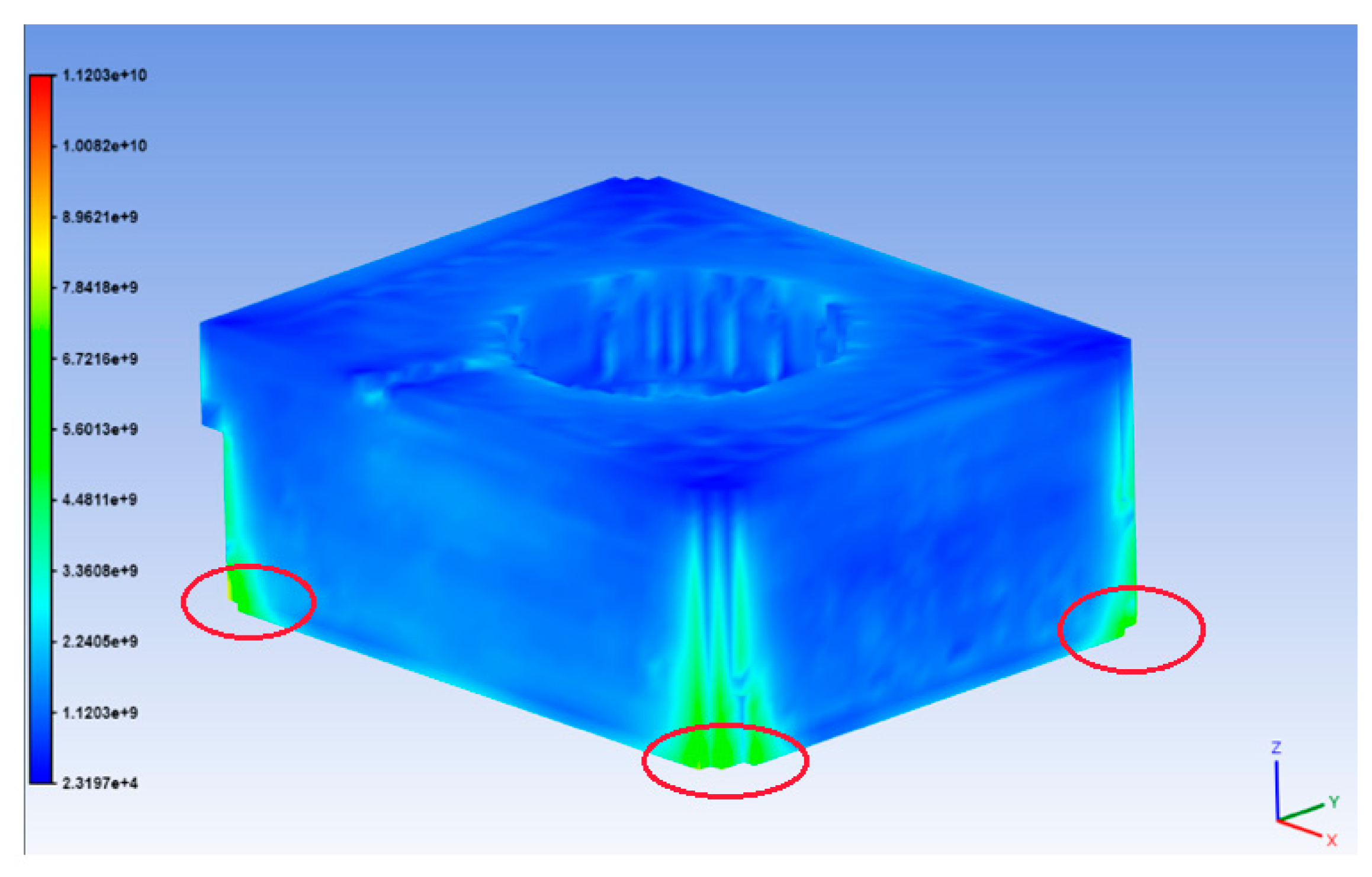
Figure 8. The thickness of the wall of external areas and stepping from the mounting holes and cooling supply is 5 mm for the proposed alternative. A perforated hole was placed in the bottom part for removal of excessive dust after completion of the manufacturing process. Subsequently, the analysis of mechanical processes during manufacturing via the DMLS technology with the machine and material parameters identical to those of the original monolithic-shaped intermediate piece was performed.
Figure 9 shows that maximum overall stress is reduced to a level of 1.12 × 10
10 Pa and does not act in critical points where the manufactured shaped intermediate piece was detached from the base plate of the machine. The value of stress occurring in the detachment spots is at the level of 4.3 × 10
9 Pa. The entire distribution of stress within the frame of the model is more balanced when compared to the original model.
Not only the reduction of overall stress but also the reduction of stress in the individual directions can be observed, as well as the reduction of overall and some partial shifts when compared to the original model. The values of partial stress are given in
Table 2. These maximum stresses are concentrated in the extreme positions of the part and are indicated in
Figure 8. These are critical places where the part was torn from the base plate.
The comparison of the monitored parameters of the proposed alternative consisting of the elements in the shape of a star with the original full model is shown in the graph on
Figure 10. The data show that the proposed solution with the internal structure built from the elements in the shape of a star reduces occurring residual stress. The reduction of the stress exceeds 50% when compared to the full volume. The significant indication is also the stress occurring in the
z-axis where the highest reduction can be observed; thus, the assumption that this stress represents an important factor influencing the formation of cracks and occurrence of detachment of the manufactured component part from the base plate of the machine can be made.
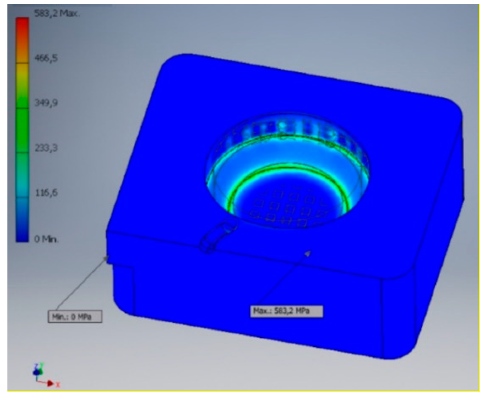
3.6. Strength Analysis of the Proposed Alternative
For comparison of the original model of the monolithic-shaped intermediate piece to the shaped intermediate piece subjected to the application of the internal topology with the cells in the shape of the “star”, which according to simulations of mechanical processes during the DMLS procedure, showed the best parameters, the Autodesk Inventor program was used again with the initial loading represented by intake pressure with the same nominal value of 20,000 psi as in the case of the original-shaped intermediate piece. The strength analysis with the acting Von Mises stress shown in
Figure 11.
4. Assessment of the Obtained Results
The present paper focused on the origin of deformations, cracks and fractures on the observed shaped insert intended to be used for plastic injection. The shaped insert has been fitted with the conformal cooling that ensures better cooling performance; however, it is impossible to manufacture it via the standard manufacturing processes. The selected manufacturing technology was the DMLS method that belongs to the set of additive manufacturing technologies.
The observed parameters in the manufacturing process simulation included the resulting total stress, the partial stress per direction, and total and partial displacements. The application of the topology optimization has a major impact on the observed parameters, since it has been shown as a part of the internal structure optimization and the analysis of these proposals. The most suitable solution was the internal structure application in the star-shaped elements.
The analysis of the obtained data also showed that apart from the residual stresses reduction and deformation reduction, the internal topology application has an effect on the mechanical properties of the final part. When examining the mechanical properties, the original and proposed alternative were subjected to the strength analysis simulating its application in real life operation. The results of the strength analysis show that the shaped insert, which has been optimized from the point of view of internal topology, reduces the total stress under load by 50% when compared to the original-shaped insert. It is clear that the largest decline is observed in the direction of the z-axis when dealing with the partial stress, despite the fact that in the given axis the highest load is assumed. Based on these finding, it can be stated that the application of the structural topology optimization has a positive effect not only on the manufacturing itself but also on the final product.
To conclude, the appropriate application of the structural optimization topology and compliance with the basic principles and limitations that apply to the design of parts manufactured via the DMLS technology can achieve effective and economical results while maintaining the requirements for the given part as well.


