Article

Investigation of Steel Fiber-Reinforced Mortar Overlay for Strengthening Masonry Walls by Prism Tests

1
Department of Architecture, Incheon National University, Incheon 22012, Korea
2
Division of Architecture and Urban Design, Incheon National University, Incheon 22012, Korea
*
Author to whom correspondence should be addressed.
Appl. Sci. 2020, 10(18), 6395; https://doi.org/10.3390/app10186395
Submission received: 25 August 2020 / Revised: 8 September 2020 / Accepted: 10 September 2020 / Published: 14 September 2020

Abstract

:
A strengthening method using steel fiber-reinforced mortar (SFRM), proposed for the seismic retrofit of masonry buildings, is verified experimentally in this study. The SFRM is overlaid on masonry walls directly, which is possible to implement while the building is occupied for residence. First, tests of workability and material strengths were conducted for SFRM itself in order to find SFRM mixing ratios appropriate for overlay construction and strengthening. Then, masonry prisms were produced using two types of bricks and strengthened with SFRM for the chosen mixing ratios and test variables such as the number of overlaid sides and the fiber volume fraction. Compressive strength tests and diagonal tension tests for those specimens were conducted. Both compressive and shear strengths were improved the most highly by overlaying the SFRM with a fiber volume fraction of 1.3%, which is the highest among the test variables, on both sides. Overlaid SFRM tends to be detached without cracking almost at the maximum strength in both compression and diagonal tension tests. For red clay brick prisms, the compressive and shear strengths increased by up to 61% and 138%, respectively. For concrete brick prisms, the compressive and shear strengths increased by up to 26% and 67%. Finally, a design formula for the shear strength of strengthened masonry prisms is compared with the experimental results, and it is observed that the design formula gives slightly higher results.

1. Introduction

Unreinforced masonry is one of representative structural systems for buildings that have been damaged severely in most major earthquakes worldwide. Recently, two major earthquakes occurred in Gyeongju and Pohang, respectively, located in South Korea caused significant damage to many buildings although those earthquakes have a moderate level of local magnitude, 5.8 and 5.4, respectively. Unexceptionally, bearing walls in unreinforced masonry buildings and external masonry veneers were reported as building components damaged the most significantly in the two earthquakes.
The mechanical property of masonry is difficult to predict because masonry is composed of different materials, i.e., masonry units and type or material of joint, and strongly influenced by workmanship strongly [1]. In particular, masonry units have different dimensions and shapes and are made of diverse materials, such as adobe and concrete. Masonry walls also fail in diverse modes such as diagonal cracking, horizontal sliding, rocking, and corner crushing. The mechanical characteristics of masonry have been investigated through experimental works by many researchers. One of the representative reasons for this is that the mechanical characteristics of masonry are considerably influenced by local materials. Narrowing down the scope of the literature to the Korean masonry materials, the following research works are available in the literature. Yu and Kwon (2011) [2] compared mechanical characteristics of masonry prisms produced using either cement or lime for joint mortar based on compression and diagonal tension tests. Kim et al. (2001) [3] performed compression and diagonal tension tests for the masonry prisms produced using joint mortar with various mixing ratios, and proposed empirical equations for the compressive strength of joint mortar and elastic modulus of masonry prisms. Yang et al. (2019) [4] proposed a shear stress–strain relationship through diagonal tension tests of masonry prisms for numerical analysis of masonry walls.
Most Korean masonry buildings are low-rise buildings and have not been designed seismically, even though those were constructed after the Korean Building Acts introduced seismic design provisions in 1988. The structural system of Korean masonry buildings is usually unreinforced masonry, of which vulnerability to earthquakes is well-known, as mentioned above. As a result, social demand for strengthening methods that can be installed easily with low cost is increasing in Korea after the two recent earthquakes. Choi et al. (2010) [5] studied seismic retrofit of unreinforced masonry walls using shotcrete overlay, which was made of Engineered Cementitious Composite (ECC) containing Polyvinyl Alcohol (PVA) fibers. They validated the effect of shotcrete overlay to enhance both strength and deformability experimentally. Taghdi et al. (2000) [6] showed that the shear strength and ductility of masonry walls and reinforced concrete walls were increased by attaching steel strips with concrete anchors. Ghiassi et al. (2012) investigated bond-slip behavior for masonry strengthened with different FRP materials both numerically and experimentally [7]. In addition, Ismail et al. (2011) [8] proposed a method to stitch masonry units with twisted steel bars that are placed in the groove made on the surface of the masonry and filled with mortar. Darbhanzi et al. (2014) [9] conducted a seismic retrofit of unreinforced masonry walls, which comprises the addition of two vertical steel ties on both edges of the walls, and anchored to the top and bottom of the walls. Silva et al. (2014) [10] strengthened unreinforced masonry by injecting lime grout, confirming that the strength and deformation capacity of the masonry increase two times and three times, respectively. In addition, as with this study, several researchers have conducted experimental studies to strengthen unreinforced masonry using overlay methods. Almeida et al. (2015) [11] strengthened unreinforced masonry by overlaying polypropylene fiber reinforced mortar (PFRM) and carbon fiber mesh (CFM). D’Ambrisi et al. (2013) [12] strengthened unreinforced masonry walls with three types of polymeric mesh attached with mortar plastered on the walls. Benedetti (2019) [13] strengthened masonry walls using glass fiber mesh-reinforced mortar (G-FRM) so that the shear strength of the masonry walls increased by more than 100%, even with a 15 mm or smaller thickness of strengthening layers on the two wall faces. In most preceding studies, fiber mesh or wire mesh is usually used in the overlaying method for strengthening masonry walls.
In this study, an efficient method to strengthen unreinforced masonry walls using a steel fiber-reinforced mortar (SFRM) overlay. The proposed overlaying method has the advantage of constructability during residence of occupants. In addition, plastering work does not require high workmanship and can be applied to the vicinity of openings without cutting or splicing. Above all, mortar can be integrated with masonry, considering that it has been used for the joint and finishing of masonry. However, the brittle behavior of plain mortar is similar to masonry. It is necessary to add reinforcement appropriate for plastering material to improve mechanical behavior of masonry walls after retrofit. SFRM is a cement composite incorporating steel fibers which improves brittle behavior of mortar as well as mechanical properties such as tensile strength and toughness. Generally, steel fibers are known to have better strength and stiffness than organic fibers such as Polyethylene (PE), Polypropylene (PP), Nylon, etc., but relatively long and thick dimensions make those difficult to apply steel fibers to thin mortar overlay. On the other hand straight or hook-type steel fibers commonly used in construction fields are relatively stiff and difficult to plaster in a thin layer without balls and protrusion, of which the latter may cause human injury. As a result, this study adopted Amorphous Steel Fibers (ASF), which reinforces mortar effectively in spite of its relatively short length due to better bonding characteristics owing to the thin shape and surface roughness.
In this study, the effect of SFRM for strengthening masonry walls was assessed based on the compressive and diagonal tension strength for masonry prisms. Those strength parameters are used to define the lateral force-resisting capacity of masonry walls in a major failure mode such as toe-crushing or diagonal tension failure, as stipulated in ASCE 41-17 [14]. In order to build strengthened prism specimens, a recommended SFRM mixing ratio with both strengthening efficiency and overlay constructability is derived based on constructability tests for fresh mortar, compression and tension tests for hardened mortar specimens for various mixing ratios, since the characteristics of SFRM strongly depend on the type of fiber, fiber volume fraction, and mixing ratio of mortar. Then, the performance of the strengthening method is evaluated by compressive and diagonal tension tests of masonry prisms with and without SFRM overlay to which the recommended mixing ratio of the mortar. This study concentrates on two representative types of unreinforced masonry. One is made of red bricks and usually used as an exterior veneer. The other is concrete bricks, usually used for bearing walls. For easy construction, only SFRM was used, without additional glass fiber or wire mesh. Finally, the applicability of existing design equations is investigated based on the measured strengths of prism specimens.

2. Derivation of Appropriate Mixing Ratio for SFRM

The main objective of developing an appropriate mixing ratio for SFRM is to obtain higher compressive and tensile strengths as well as a workability suitable for overlay construction. Flow tests and cohesion tests of fresh SFRM were conducted for diverse mixing ratios in order to select the candidate mixing ratios that are the most appropriate for overlay construction on masonry. Then, compressive and tensile tests were conducted for hardened SFRM specimens produced with the candidate mixing ratios, and the most appropriate mixing ratio is determined.

2.1. Mixing Design

Regarding a mixing ratio appropriate for overlay construction, the Korean Construction Standard (KCS) 41 16 02 [15] set forth two standard mixing ratios for plastering mortar, of which cement-to-sand ratios are 1:2 for exterior walls and 1:3 for interior walls, respectively. However, in case of mortar with steel fibers, various cement-to-sand ratios are investigated from preceding studies and summarized in Table 1.
The volume of sand is relatively small, so that the highest equals two times the volume of cement in Table 1 in order to enhance binding action for fibers. In light of the preceding studies given in Table 1, three trial cement-to-sand ratios between 1:1 to 1:2 in combination with different water-to-cement ratios were chosen and summarized in Table 2. In addition, a mixing ratio utilizing superplasticizer was introduced to prevent the development of fiber balls and improve fluidity, referring to Park et al. (2016) and Shabdin et al. (2017) [19,20]. Additional tests using fiber volume fractions 1.0% and 1.3% were performed for the last two mixing ratios in Table 2 that showed superior workability and cohesion compared to others. In the designation of mixing ratios for SFRM defined in Table 2, S/C means the volume ratio of sand over cement, and W/C means the weight ratio of water to cement as noted in the foot note.

2.2. Materials

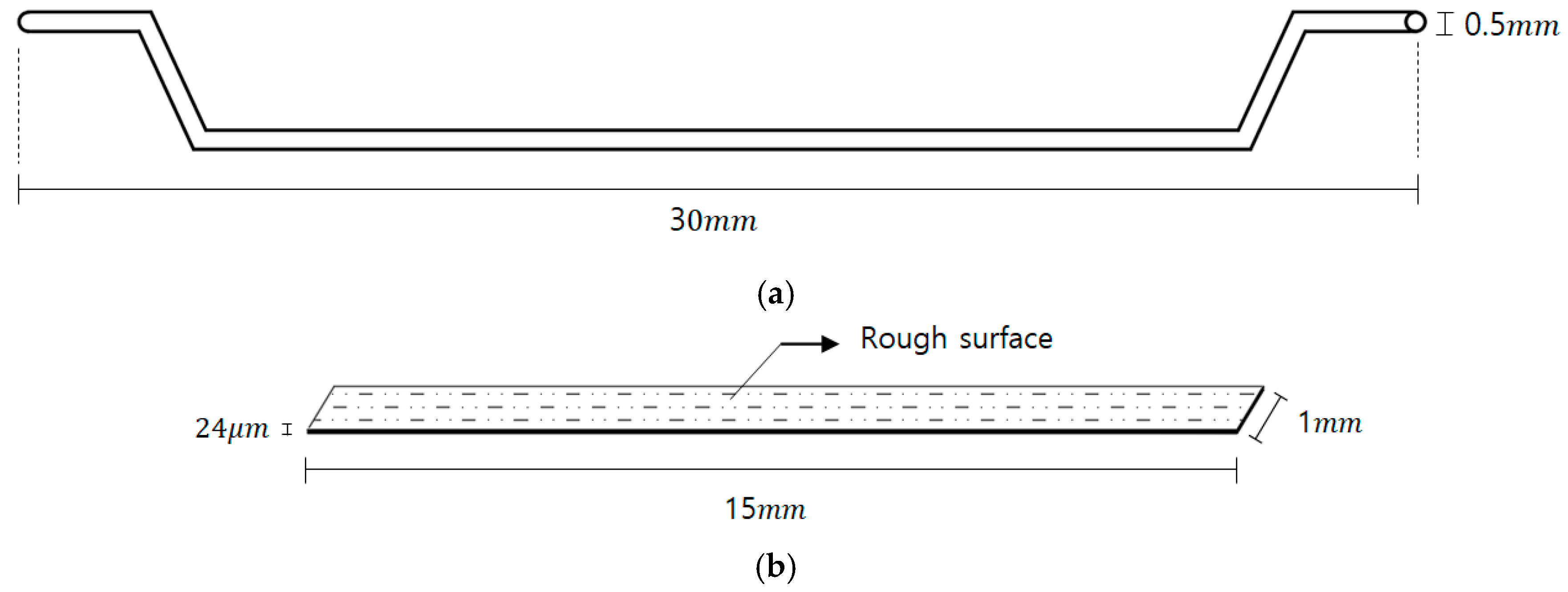
Mortar in this study was comprised of ordinary Portland cement for binder and standard river sand with a specific gravity of 2.6 for fine aggregate. The superplasticizer included in mixing variables is a polycarbonate type. The steel fibers used for SFRM are amorphous steel fibers, which proved effective in improving the flexural performance of beam type structural components by Lee and Choi (2014) [21]. The appearance of the amorphous steel fibers is shown in Figure 1.
The physical properties of the amorphous steel fibers are summarized in Table 3. According to Ku et al. (2014) [22], the amorphous steel fiber not only has excellent tensile and flexural strength compared to ordinary steel fibers, but also increases adhesion to concrete with rough surface. In addition, it shows good flexibility and dispersibility in mixing. Consequently, the above characteristics for the amorphous steel fibers were supposed to help the uniform distribution of fibers in SFRM in spite of relatively small thickness of overlay on existing walls.
The same procedure of mixing was applied to all mixing ratios to ensure uniform quality. Firstly, cement and fine aggregate were dry-mixed at low speed for 1 min. Secondly, water and admixture, if specified, were added and mixed for 1 min at low speed and then for 3 min at high speed. Finally, mixing was finished by adding fibers and mixing for 2 min 30 s.

2.3. Workabiliy Tests

Plastering work requires fresh mortar to have adhesion enough to prevent flowing down on the vertical face of masonry walls. However, workability represented in the form of a specific slump or flow appropriate for plastering work of fresh mortar is not clearly prescribed in Korean Industrial Standards (KS) and Korean Construction Specifications (KCS) such as KS F 4716 [24], KS F 2262 [25], KCS 41 16 01 [26] and KCS 41 16 02 [15], which only provide testing methods for hardened mortar or specifications for plastering work. Instead, recommended values of flow were found from the literature survey. Lee (2009) [27] suggested an appropriate flow range of lightweight mortar mixed with gypsum, of which fire resistance performance was tested, from 170 to 210 mm. Park (2010) [28] suggested a flow of 180 mm suitable for constructability in a study of diverse mortar for interior finishing plaster. In this study, the target flow of SFRM was determined to be 180 mm in light of preceding research. Flow table tests for various mixing ratios of SFRM were carried out in accordance with KS L 5111 [29].
Measured flow values are plotted with respect to the fiber volume fraction in Figure 2. The flow value obtained for S/C20-W/C25-AD01 containing superplasticizer, and S/C20-W/C50 and S/C20-W/C50 with a relatively high water–cement ratio exceeded the target, 180 mm, by 20 mm or higher. The fiber volume fraction does not have clear influence on the flow for those specimens. However, flow values for other specimens are lower than 200 mm and tend to decrease slowly as the fiber volume fraction increases. The three groups of specimens corresponding to S/C20-W/C40, S/C15-W/C35, and S/C10-W/C32 had flow values that were adequately close to the target, 180 mm.
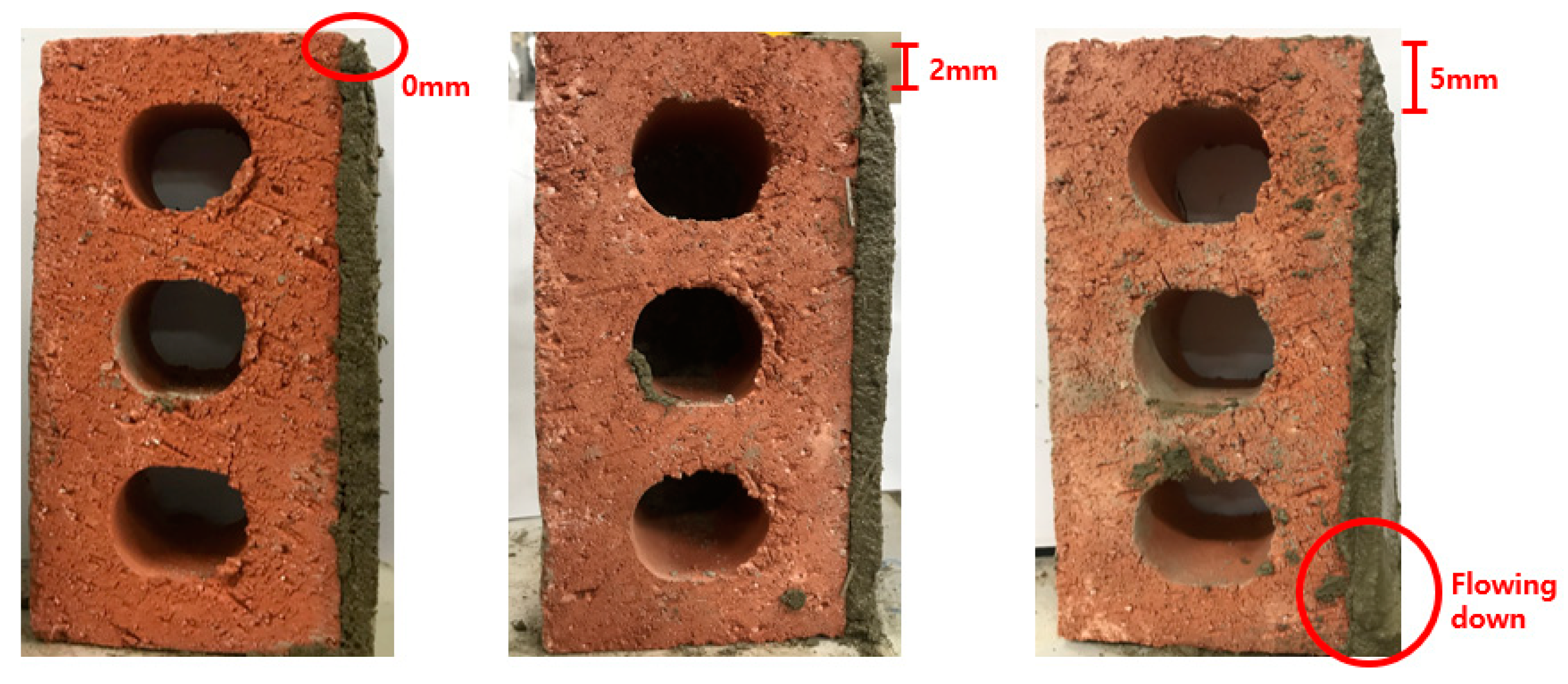
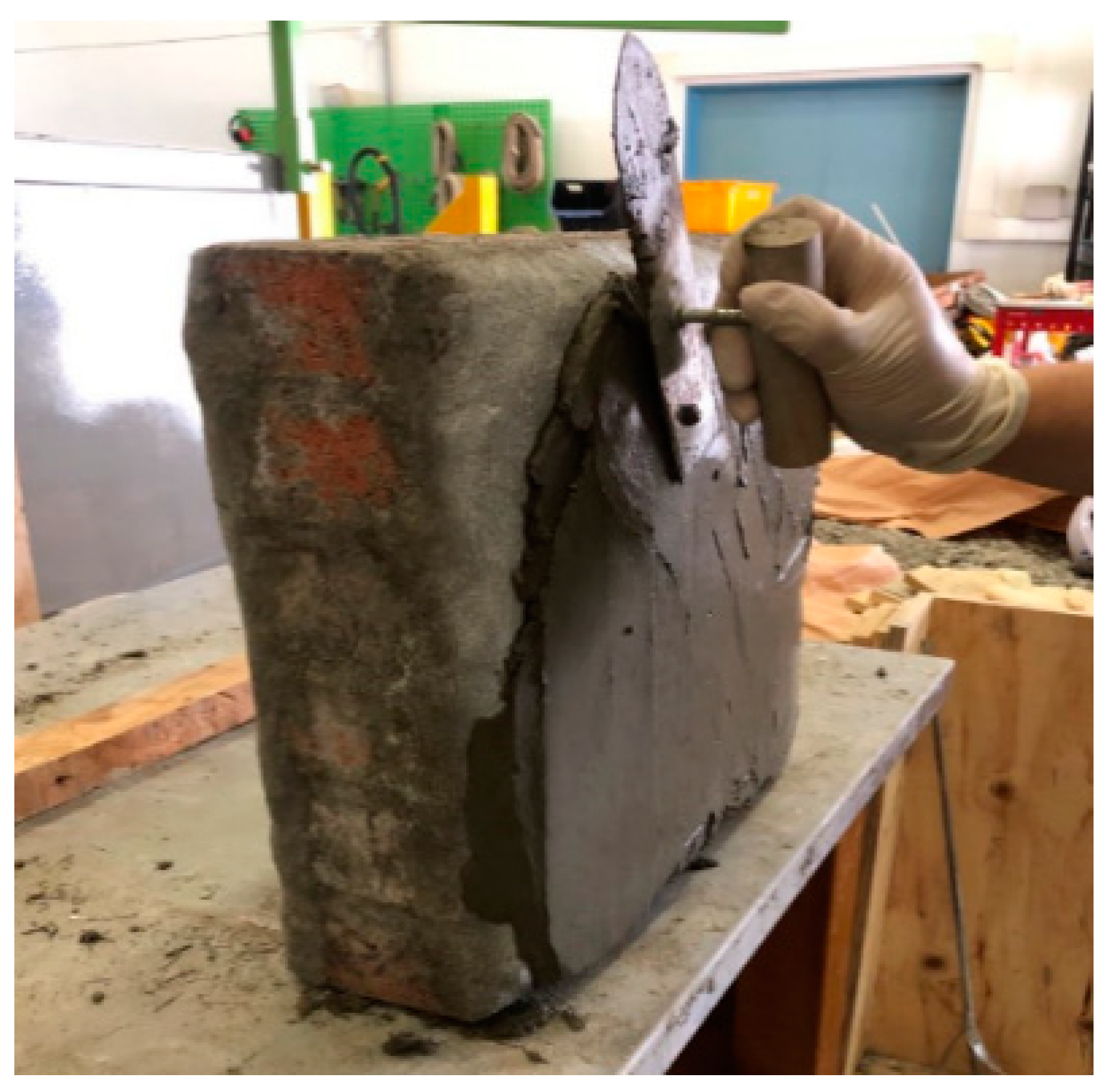
The adhesion of SFRM to bricks was tested using a procedure proposed by the authors, since test methods and acceptance criteria for the adhesion of fresh mortar are not specified in the Korean or international standards investigated by authors, as mentioned above. The test method is to check the deflection of the plastered SFRM in 1 min after a trial plastering of SFRM with a thickness of 2.5 mm as shown in Figure 3, and the measured flow values and overlayable thickness are summarized in Table 4. The trial plastering and measurement of the deflection was conducted repeatedly and recorded. The adhesion of SFRM for each trial plastering was evaluated as good, normal, and poor for a deflection of 0, 2, and 5 mm, respectively. The maximum plastered thickness for which accumulated total deflection was restrained under 2 mm are summarized as the overlayable thickness in Table 4. The overlayable thickness for SFRM tends to decrease gradually as the fiber volume ratio increases. The S/C20-W/C25-AD01 specimen containing superplasticizer and the S/C20-W/C50 with a relatively high water–cement ratio show relatively low overlayable thickness that does not exceed 7.5 mm. The low overlayable thickness may lengthen the construction periods because subsequent plastering shall be conducted on previous overlay, which hardened sufficiently. On the other hand, the two mixing ratios of S/C20-W/C45 and S/C10-W/C32 showed good adhesion performance with all the overlayable thickness higher than or equal to 10 mm in Table 4. Based on the adhesion test result, the thickness of the SFRM for a single trial of plastering was decided to be 10 mm for the production of strengthened masonry prism specimens

2.4. Compressive and Tensile Tests

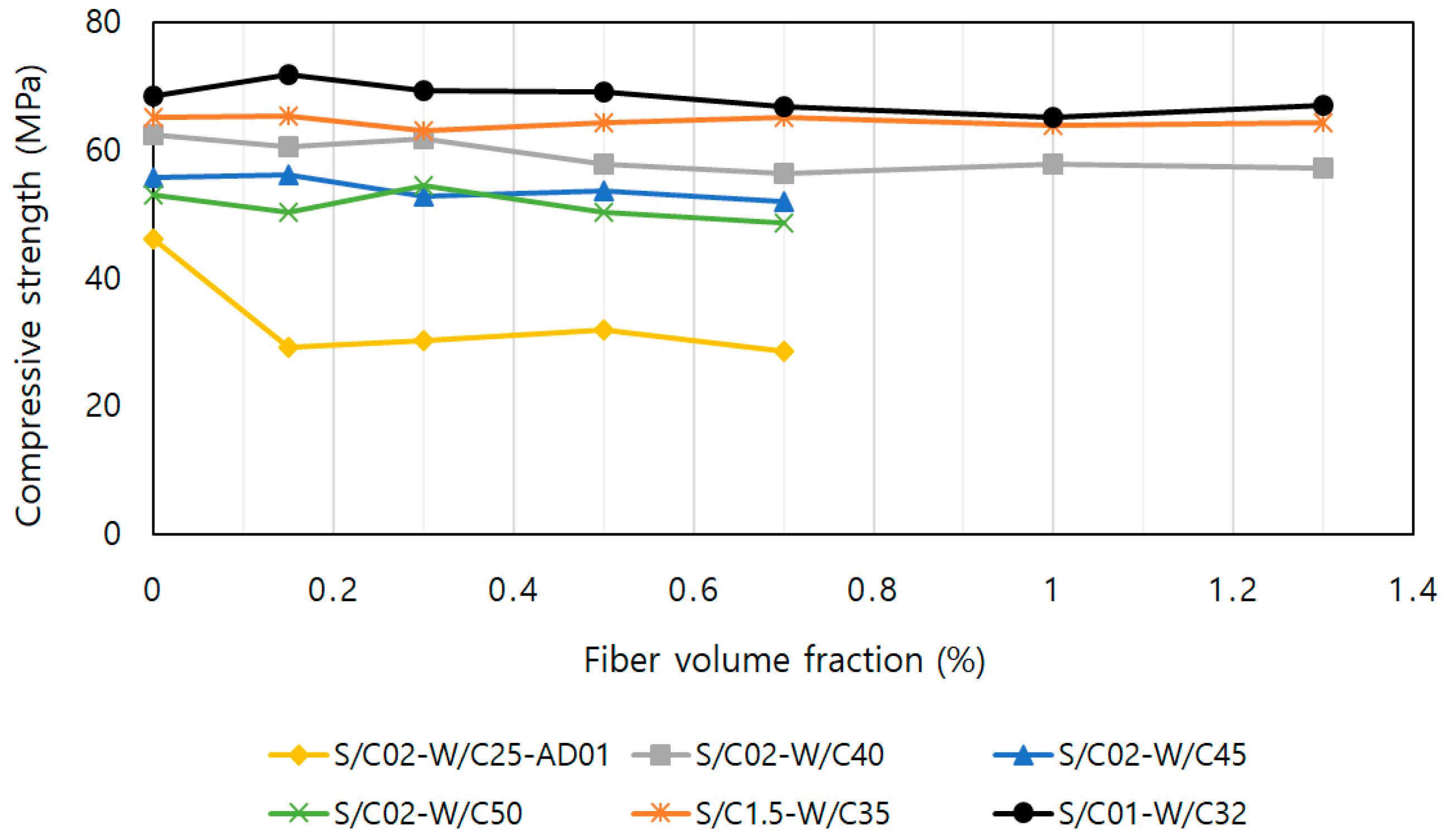
The compressive and tensile strength for SFRM with diverse mixing ratios given in Table 2 were tested in accordance with KS L 5105 [30] and KS L5104 [31], as shown in Figure 4. The specimens for compressive tests were made in cubes with a 50 × 50 × 50 mm dimension in accordance with KS L 5105 [30]. The specimens for tensile tests were made in briquettes shown in Figure 4b, in accordance with KS L 5104 [31]. All the specimens were cured in water at room temperature for 28 days. For each mixing ratio, both compressive and tensile strengths were measured and averaged for three specimens, respectively. A universal testing machine (UTM) was used for compression tests, and a hydraulic oil pump was used for tension tests. The compressive strengths for different SFRM mixing ratios are plotted with respect to the volume fraction of amorphous steel fiber in Figure 5. It is observed that the fiber volume fraction does not affect the compressive strength of the SFRM significantly. The highest compressive strength 67 MPa was obtained for S/C10-W/C32, followed by S/C15-W/C35, and S/C20-W/C40 in a descending order. Based on the test result, the compressive strength of SFRM is more influenced by increased cement volume and reduced water cement ratio rather than the fiber volume fraction.
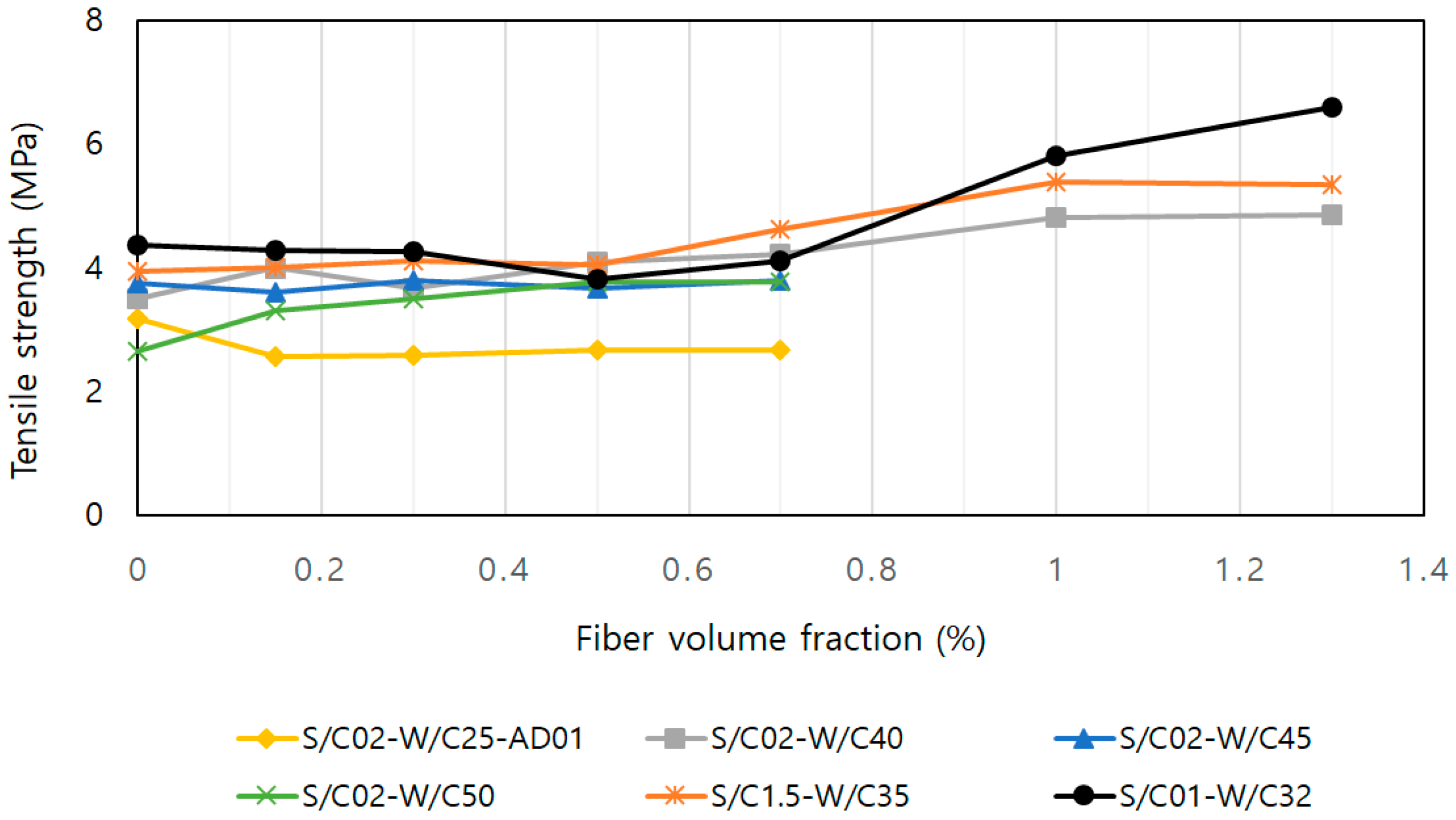
The tensile test results are plotted in Figure 6. The five mixing ratios except S/C20-W/C25-AD01 show an increasing trend with respect to the fiber volume fraction. In more detail, it is observed that the tensile strength of SFRM increases little with 0.7% or less steel fiber volume fraction. However, the tensile strength of SFRM with 1.0% or higher steel fiber volume fraction increases compared to mortar without fibers by about 30%. S/C10-W/C32 with a relatively low sand–cement ratio and low water–cement ratio achieves a tensile strength of 6.6 MPa at with 1.3% steel fiber volume fraction resulting in a strength enhancement of 50%. From this observation, it is supposed that the increased amount of cement in paste enhances bond of steel fibers and makes a corresponding contribution to tensile strength.

2.5. Recommended Mixing Ratio

Table 5 summarizes the mixing ratios that achieved target performance for each test category. In Table 4, S/C20-W/C40, S/C15-W/C35, and S/C10-W/C32 have flow characteristics corresponding to the target flow, 180 mm. In the adhesion test, only two specimens S/C20-W/C45 and S/C10-W/C32 achieved the overlayable thickness of 10 mm or higher for fiber entire fiber volume fractions. Therefore, only S/C10-W/C32 is a common candidate for recommendation from both workability tests. In addition, S/C10-W/C32 with the fiber volume ratio of 1.3% shows the highest tensile strength among all the tested mixing ratios while compressive strength did not show a meaningful increase in strength with respect to the fiber volume fraction. As a result, the mixing ratio S/C10-W/C32, which showed adequate characteristics for all four evaluation categories including flow, adhesion, compression, and tensile strength, was adopted for subsequent tests of masonry prisms strengthened with SFRM overlay.

3. Test of Masonry Prisms Strengthened with SFRM Overlay

3.1. Test Program

Tests for the compressive strength and diagonal tension of masonry prisms strengthened with SFRM overlay were performed. The tests were conducted in accordance with ASTM C 1314 [32] and ASTM E 519 [33], since the Korean Building Code does not clearly stipulate methodology and procedure for such tests of masonry prisms. The mixing ratio S/C10-W/C32 was chosen for SFRM as described in the previous section based on the result of tests for workability and strength tests. In this study, the compressive strength, shear strength, elastic modulus and shear modulus of each prism specimen were measured.

3.1.1. Specimens

The type of bricks, the number of strengthened faces, and the fiber volume ratios adopted for test variables are summarized in Table 6 with specimen names. Concrete and red clay bricks usually used for construction of bearing walls and external masonry veneers, respectively, were adopted to comprise masonry prisms and designated by C and R in the specimen names. In the specimen names, P designates the specimen without strengthening, S designates the specimen strengthened on a single surface, and B designates the specimen strengthened on both sides. The number that follows the characters in a specimen name represents the fiber volume fraction in percent in mortar overlay for strengthening. Due to lack of amorphous steel fibers, only two specimens were produced per RS1.0 and CS1.0 in Table 6.
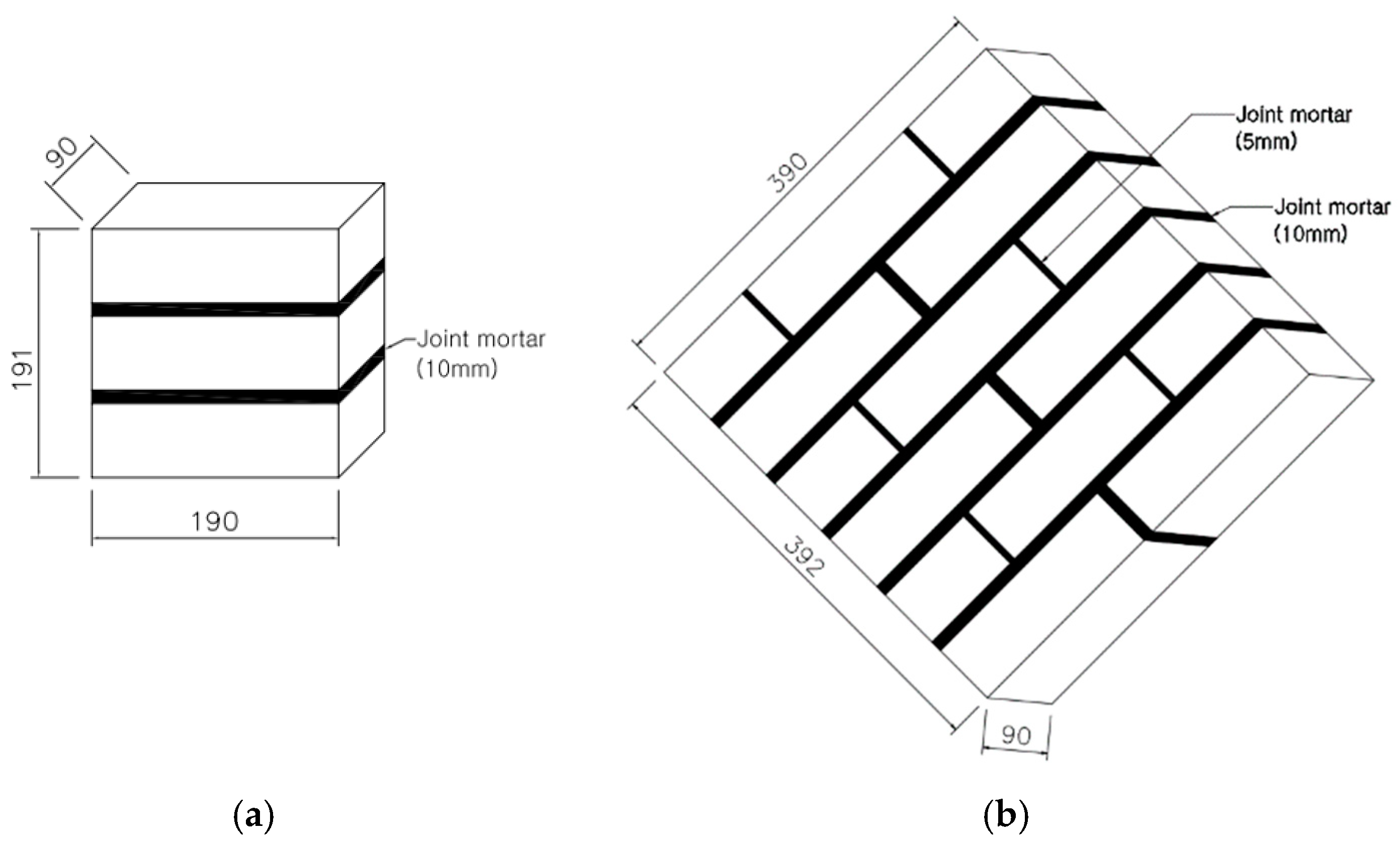
The shapes and dimensions of test specimens for compression and diagonal tension tests, illustrated in Figure 7, comply with ASTM C 1314 [32] and ASTM E 519 [33], respectively. The dimension of both concrete bricks and red clay bricks is 190 × 90 × 57 mm. Concrete bricks are hollow but red clay bricks are solid, as is usual in Korea.
The compressive strength of concrete bricks and red clay bricks tested in accordance with KS F 4004 [34] were 29.1 and 23.2 MPa, respectively. Joint mortar was made with a standard volume ratio of cement:sand = 1:3, as prescribed in KCS 41 34 02 [35]. Yi et al. (2004) [36] proposed an empirical equation to predict the compressive strength of the joint mortar with respect to the sand-to-cement weight ratio. The test result for the compressive strength of the joint mortar used in this study that were cured in water was 33 MPa, which was almost similar to the 32.5 MPa predicted in accordance with Yi et al. (2004) [36].
The prism specimen for compression strength test has a total of three layers laid-up in a stack bond pattern, while the diagonal tension prism has a total of six layers laid-up in a running bond pattern as illustrated in Figure 7. Both vertical and horizontal joints between bricks were filled with mortar without a visual gap. As shown in Figure 8, strengthened prisms were produced by plastering SFRM repetitively on bare masonry prisms 28 days after lay-up. A total thickness of 30 mm were plastered in three times with an interval of 24 h, according to the adhesion test result described previously. Water was sprayed on the bare masonry before plastering SFRM. All of the SFRM-overlaid prisms were cured in air dry conditions and room temperature.

3.1.2. Test Setup and Loading Protocol

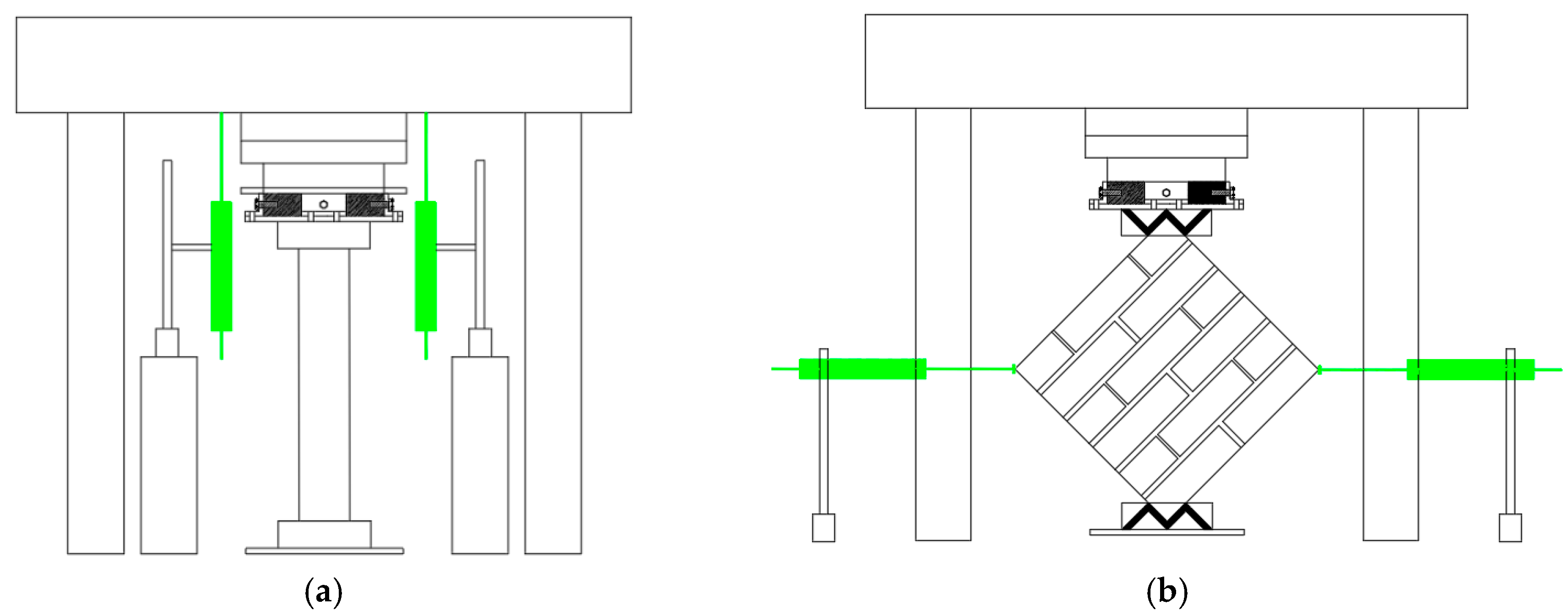
Both compression and diagonal tension tests were conducted using 200-ton universal testing machines (UTMs). Monotonic loading in compression test was applied at a rate of 1.0 mm/min and diagonal tension test, which was expected to have relatively low loading capacity, was applied at a rate of 0.6 mm/min. Both types of tests were terminated when the resistance of the specimens decreased to 70% of the peak. For the compression test of masonry prisms, the vertical deformation of a masonry prism specimen was measured by setting linear variable displacement transducers (LVDTs) at the front and rear of a specimen, as shown in Figure 9. The average of the two measurements is used as the compressive deformation of the specimen. In case of the diagonal tension test of masonry prisms, the diagonal deformation in the vertical direction of the specimen rotated by 45° was measured in the same way as for the compression test. Additionally, the diagonal deformation in the horizontal direction of the 45°-rotated specimen was measured using two LVDTs set in the plane of the specimen at the right- and left-hand side corners, as shown in Figure 10. The horizontal deformation was calculated as the sum of the displacements from the two horizontal LVDTs.

3.2. Result of Tests for Masonry Prisms

3.2.1. Strength and Modulus of Elasticity

The compressive strength of the masonry prism was calculated in accordance with ASTM C-1314 [32] considering the correction factors for the height-to-thickness ratio. In accordance with ASTM C-1314, the net cross-sectional area for red clay bricks with a hollow cross section was deemed to be the gross cross-sectional area because the net cross-sectional area is higher than or equal to 75% of the gross cross-sectional area. The elastic modulus was calculated using Equation (1) in accordance with Korean Building Code (KBC) 2016 [37]
E m = 0.33 σ 0.05 σ ϵ 1 ϵ 2
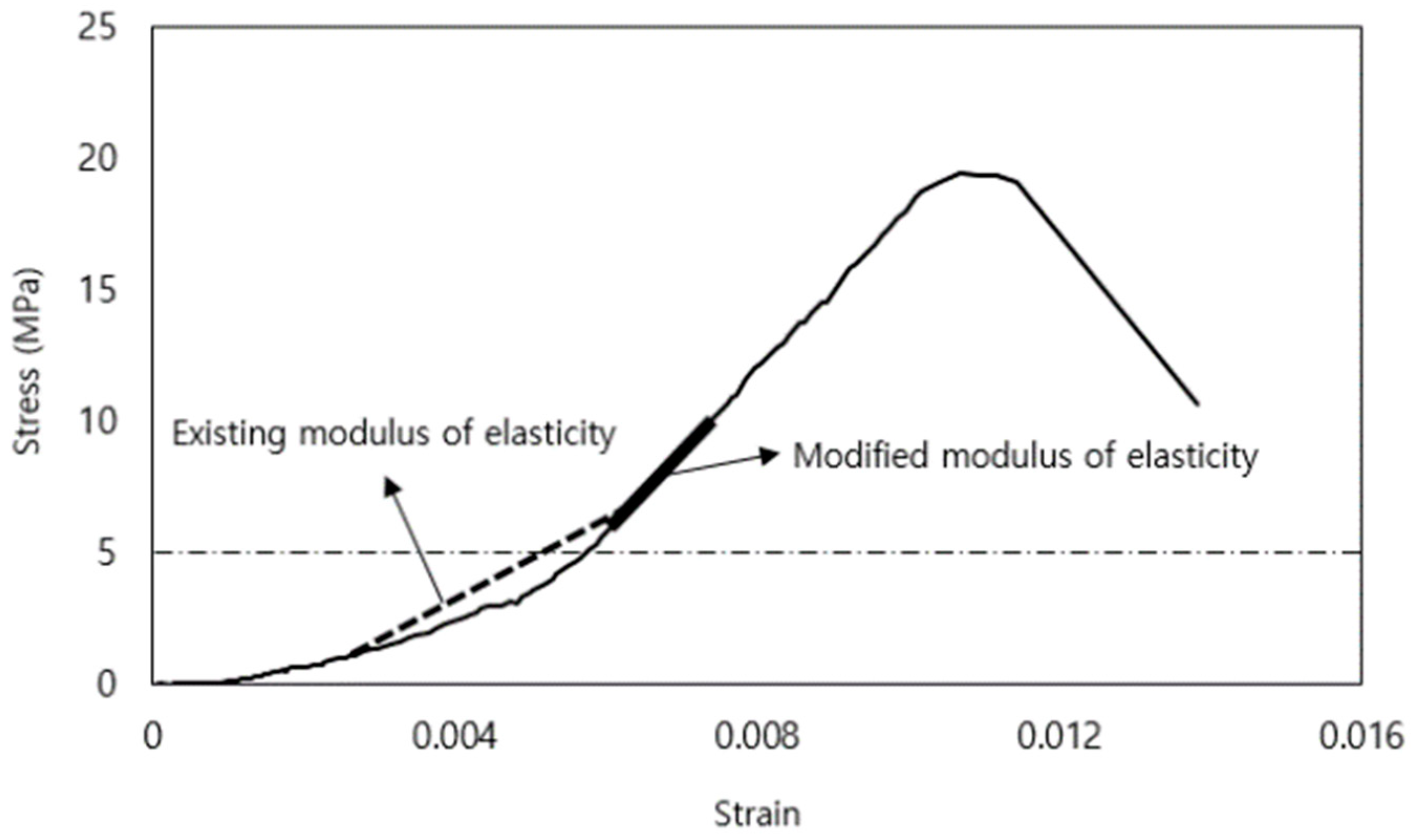
where E m is the elastic modulus for the masonry prism (MPa), σ is the compressive strength of the masonry prism (MPa), and ϵ 1 and ϵ 2 are strains at 5% and 33% of the maximum stress, respectively. However, in the actual calculation of ϵ 1 and ϵ 2 , only the stress–strain curve higher than the horizontal broken line in Figure 11, at which the slope begins to be almost constant, was taken into account, because the initial growth of stress is too slow.
The shear strength and shear modulus from diagonal tension tests for masonry prisms were calculated in accordance with ASTM E-519 [33], in which the net area of the masonry unit is used for the calculation of shear stress. The shear strain for the calculation of shear modulus was calculated based on the vertical and horizontal displacement measured, as described in Figure 10.

3.2.2. Compression Test Result

The result of the compression tests for masonry prisms made of red clay bricks and concrete bricks is summarized in Table 7 and Table 8, respectively. The average compressive strengths for red clay brick prisms and concrete brick prisms without strengthening designated with RP and CP in Table 7 and Table 8 are 14.5 and 16.3 MPa, respectively, which are not significantly different. However, the elastic moduli for RP and CP are 1382.7 and 3951.1 MPa, respectively, which shows significantly higher stiffness for concrete brick prisms than for red clay brick prisms. Mechanical properties such as compressive strength and elastic modulus for red clay brick prisms were enhanced effectively by overlaying mortar. Comparing RB0 and RB1.3 in Table 7, the SFRM with a sufficiently high fiber volume fraction, at 1.3%, is significantly more effective than the mortar without fibers. The highest compressive strength among red clay brick prisms was obtained for RB1.3 among strengthened red clay brick prisms and the amount of increase was 61%. In a similar manner, CB1.3 showed the highest compressive strength among concrete brick prisms in Table 8 due to the largest amount of the strengthening overlay and steel fibers. However, the increase in the compressive strength reaches only 26% of the strength for bare prisms denoted by CP and the elastic modulus decreased by 6%.
Figure 12 and Figure 13 plot compressive stress-strain relation for prisms made of red clay bricks and concrete bricks, respectively. In these figures, it is observed that RB1.3 specimens show the most prominent enhancement in both strength and deformability. In case of CB1.3, the strength increase is significant only in one specimen, but deformability is enhanced for all three specimens. Consequently, the strengthening effect of SFRM for masonry prisms in compression is more remarkable for red clay brick prisms than for concrete brick prisms. From the above observation, it is supposed that the weaker and softer characteristics of red clay bricks make the strengthening effect of SFRM more prominent in comparison with application on concrete bricks.
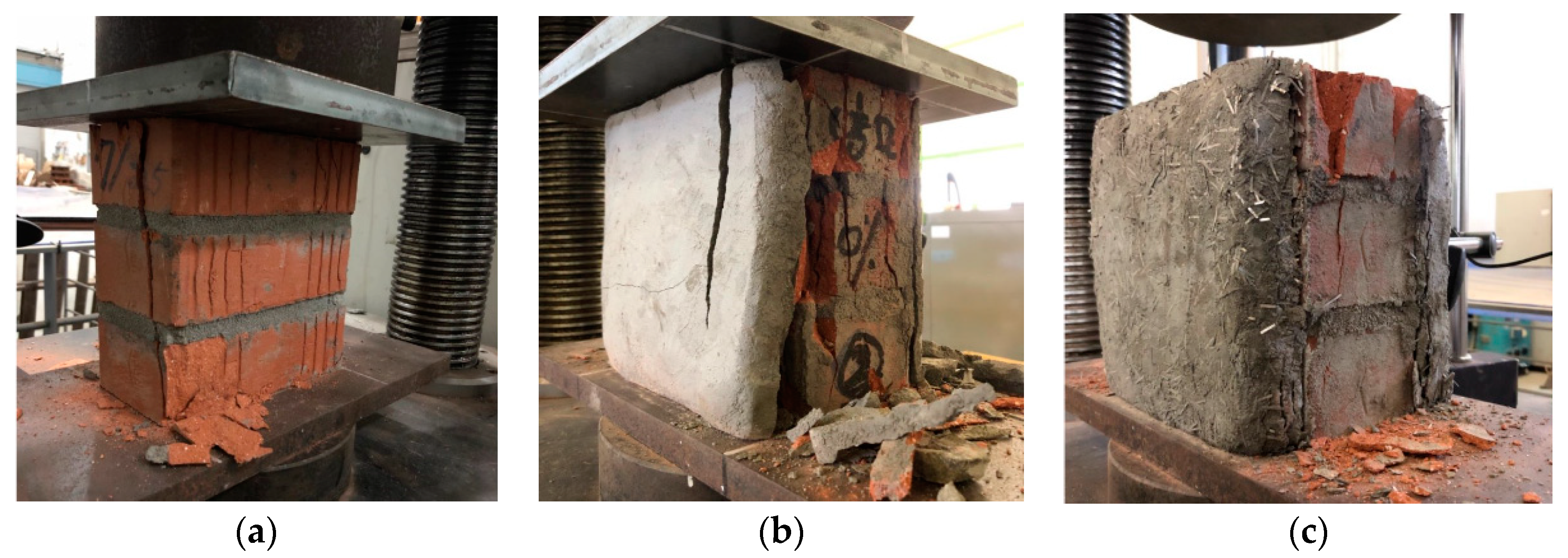
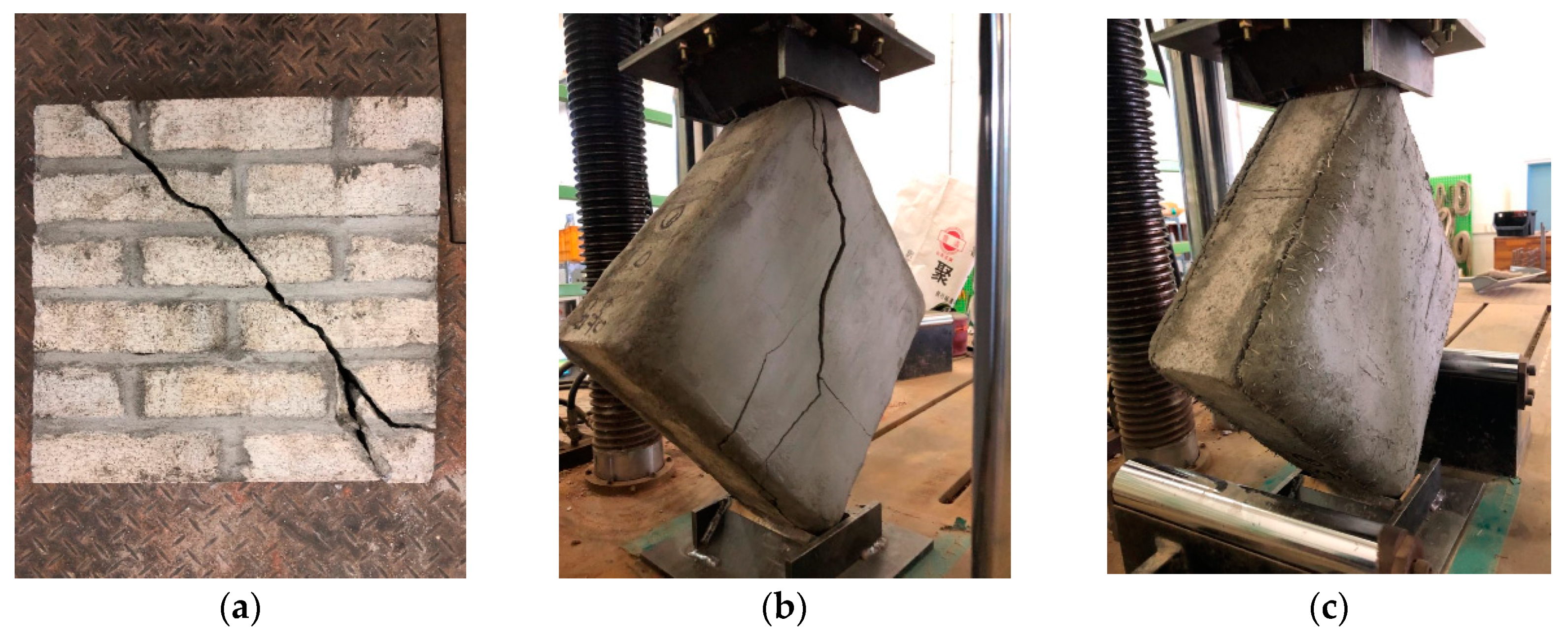
The pictures of masonry prisms for compression tests after the termination of tests are presented in Figure 14. The specimen RP without strengthening failed with vertical cracks, as shown in Figure 14a. The strengthened specimens RB0 and RB1.3 failed accompanying separation between mortar overlay and masonry, as shown in Figure 14b,c. In case of RB0, the mortar overlay without fibers plastered on masonry was split in addition to separation from masonry, as shown in Figure 14b. The mortar overlay without fibers were completely detached from the surface of the masonry and the masonry between the two strengthening overlays was crushed almost at the same time as the separation of the mortar overlay occurred. On the other hand, for RB 1.3, the SFRM overlay was not damaged, but only cracks formed at the interface between the overlay and prisms around boundary edges slowly after the load reaches the peak. The crushing of masonry in RB1.3 progressed in a relatively slow manner. Based on the observed behavior of strengthened masonry prisms, the strengthening effects of SFRM overlay are expected to be improved by developing mechanical connection details between the SFRM overlay and masonry.

3.2.3. Diagonal Tension Test Result

The result of the diagonal tension test for masonry prisms made of red clay and concrete bricks are summarized in Table 9 and Table 10, respectively. The average shear strength of unreinforced concrete brick prism CP is about 1.6 times higher than that of unreinforced red clay brick prisms RP, but the average shear modulus for CP is only 1.2 times higher than that of RP. The increase rate of shear strength by mortar overlay for RS1.3, RB0 and RB1.0 is from 51 to 69%, and those for CS1.3, CB0 and CB1.0 are between 39 and 56%. The strengthening efficiency for red clay brick masonry is slightly higher than for concrete brick masonry. The maximum enhancements of shear strength are 138% and 67% for RB1.3 and CB1.3, respectively, to which the highest fiber volume fraction is applied. One of the reasons for the higher strengthening efficiency in red clay brick masonry is supposed to be the lower strength of the masonry itself, considering that SFRM with the same mixing ratios and fiber volume fractions was applied to both types of masonry materials. A similar tendency was observed by Borri et al. (2011) [38], in which masonry walls strengthened using high-strength steel wires and mortar were tested and the unreinforced test specimens with higher strength and stiffness obtained less strengthening effects. Therefore, the efficiency of the strengthening method proposed by this study is expected to be more prominent when applied to masonry in poor condition.
Regarding the shear modulus, red clay brick masonry and concrete brick masonry obtained an increase of 32% for RB1.3 and 20% for CB1.3, respectively, using SFRM with a fiber volume fraction of 1.3% on both sides. However, the increase rates of the shear modulus are relatively small compared to the increase in shear strength and the shear modulus even decreases for a number of specimen types. The increase rate of shear modulus for red clay brick masonry is slightly better than for concrete brick masonry regarding the shear strength.
The stress–strain curves obtained from the unreinforced masonry without strengthening and masonry strengthened on both sides are plotted in Figure 15 and Figure 16 for red clay brick masonry and concrete brick masonry, respectively. In the initial loading stage, difference between unreinforced and strengthened masonry is not significant, but the strengthening effects become more obvious as the strain increases. Above all, masonry prisms strengthened with SFRM exhibit much more deformation capacity compared to those strengthened with plain mortar commonly for both masonry materials.
Representative damage states of specimens after the termination of diagonal tension tests are represented in Figure 17. Failure in diagonal tension tests of masonry prisms is generally classified into three types: diagonal tension failure along the force direction, sliding failure along the horizontal mortar joint, and composite failure in which both diagonal tension failure and sliding failure occur in combination. According to Yu and Kwon (2011) [1], the compressive strength of the joint mortar higher than the compressive strength of the brick tends to result in diagonal tension failure or composite failure, while low compressive strengths of the joint mortar lead to sliding failure. In this study, the compressive strengths for joint mortar, concrete bricks and red clay bricks are 33, 29.1 and 23.2 MPa, respectively, from which diagonal tension failure or composite failure are anticipated, as observed in Figure 17a.
In case of the specimen CB0 strengthened with mortar overlay without steel fibers, brittle failure occurred in both mortar overlay and the masonry, as shown in Figure 17b. On the other hand, for the specimen CB1.3 strengthened with SFRM, the overlay detached as the load reached the peak in a similar way to the compression tests, and the condition of the SFRM at the termination of the test was good with few cracks, as shown in Figure 17c.
The damage state of the masonry beneath the mortar overlay was difficult to identify visually, so the mortar overlay was taken off after the termination of the test. From the investigation, it was observed that diagonal tension failure had occurred in the masonry prism between the two mortar overlays, as shown in Figure 18. From the above observations, it is supposed that masonry prisms strengthened with SFRM overlay failed in diagonal tension after the detachment of the overlay. Therefore, strengthening effects are expected to be improved, as in the compression test, if the integrity between the masonry and SFRM is improved.

4. Estimation of Enhanced Shear Strength

The shear strength observed in the tests are compared with those predicted using design equations. ACI 549.4R-13 [39] provides that shear strength of masonry walls strengthened with Fabric Reinforced Cement Matrix (FRCM) is calculated by combining the contribution of the masonry and the FRCM composite material, respectively, as follows
V n = V m + V f
where V n , V m and V f are the nominal shear strength, the contribution of the masonry, and the contribution of the FRCM composite material. The FRCM is a kind of mortar reinforced with grid type mesh, while SFRM is mortar reinforced with steel fibers. In spite of difference between the two types of reinforcement, the shear strength of masonry walls strengthened by SFRM is supposed to be calculated using Equation (2) considering that both FRCM and SFRM are essentially the same material for strengthening masonry walls.
The masonry prisms failed in the diagonal tension failure mode as shown in Figure 17 and Figure 18. For such a case, the shear strength of the masonry wall, V m , can be calculated using Equation (3) proposed by Li et al. (2005) [40] for the diagonal tension failure
V m , d t = t a n θ + 21.16 + t a n 2 θ 10.58 × f t × A n
where θ is the angle between horizontal and main diagonal of the wall, A n is the net area of the cross section of the masonry wall ( mm 2 ), and f t is the tensile strength of the masonry calculated as 0.67 × f m and 0.5 × f m , in which f m is the compressive strength of the masonry (MPa), for red clay bricks and concrete bricks, respectively (MPa), in accordance with Silva et al. (2008) [41]. However, diagonal tension test result for masonry prisms without strengthening was used for V m instead of calculation by Equation (3), considering the tensile strength of bricks has much uncertainty. From the peak load in the diagonal tension test, only the component parallel to the horizontal joints in the masonry prism was decomposed and assigned to V m . On the other hand, Equation (3) was used to calculate the contribution of the SFRM overlay to the shear strength, denoted by V f . In Almeida et al. (2015) [11], masonry prisms were strengthened with mortar overlay reinforced by mesh, and the contribution of mortar overlay except mesh was calculated using Equation (3). This is a reasonable approximation when the mortar joints between bricks are relatively strong and the failure is governed by masonry units such as bricks. The tensile strength of SFRM in Figure 6 was used for f t in Equation (3).
In addition, Sagar et al. (2017) [42] conducted experiments on the diagonal tension strength and out-of-plane flexural strength for masonry walls strengthened with FRCM, and proposed Equation (4) to calculate the contribution to the shear strength by FRCM
V E C C = t E C C ( z f y E C C + 0.18 f E C C L )
where V E C C is the shear strength of the engineered cementitious composite (ECC) section (kN) and was used as shear strength of the SFRM in this study, t E C C is the thickness of the overlay (mm), z is the lever arm assumed as 0.87 times the length of the specimen (mm), f y E C C and f E C C are the tensile and compressive strengths of the overlay, respectively (MPa), and L is the length of the wall (mm).
The shear strengths of masonry prisms strengthened with SFRM overlays obtained from the tests and calculations using Equations (2)–(4) are summarized for comparison in Table 11, in which the contribution of the masonry and that of the SFRM are given separately. It is noted that all the calculated shear strengths for strengthened masonry prisms are consistently higher than the corresponding experimental strengths and Equation (4) tends to overestimate the shear strengths more significantly than Equation (3).
Equation (2) assumes that both masonry and mortar overlay for strengthening fail simultaneously. However, SFRM overlay detached from the interface without damage, as shown in Figure 17c. The premature detachment of the SFRM overlay causes Equation (2) to overestimate the strength of the strengthened masonry prisms. To improve the accuracy in predicted shear strength, it is necessary to take into account the bond strength between SFRM and masonry, which requires an additional test program. Otherwise, it can be anticipated that error in strength estimation using Equations (2) and (3) will be reduced if any technique to improve the bond strength or shear connectors between masonry and SFRM overlay are applied.
In case of RB0 and CB0, the strengthened masonry prism fail with the mortar overlay cracked, as shown in Figure 17b. Therefore, the error in strength estimation given in Table 11 does not result from the premature detachment of the mortar overlay. In this case, the error may be caused by the use of Equation (3) or (4), in which material strength is for the masonry unit and mortar joint stronger than the masonry unit is assumed to exist.

5. Conclusions

In this study, material specifications of steel fiber-reinforced mortar to strengthen masonry prisms were investigated based on extensive test programs regarding both workability and strength. In addition, the strengthening effect of SFRM overlay for masonry prisms was investigated through tests for various strengthening schemes. Finally, applicability of existing design equations to predict enhanced strength is evaluated. The key findings from the experimental study are summarized as follows.
  • The mixing ratios of SFRM appropriate for plastering work on masonry walls and effective in strengthening were identified. Plastering the SFRM was more effective for the shear strength than the compressive strength and achieved 67% and 138% increases for red clay brick prisms and concrete brick prisms;
  • The higher volume fraction of amorphous steel fibers in SFRM e.g., 1.3% achieved considerably ductile behavior in the diagonal tension test in contrast to the brittle behavior observed for the plain mortar overlay;
  • The SFRM overlay was separated without damage from the masonry prisms at the failure in diagonal tension tests. For accurate estimation of enhanced shear strength, it is necessary to take into account the bond strength between the SFRM overlay and the masonry, instead of the shear strength of SFRM overlay itself. Additionally, enhancement of the bond strength is expected to improve the strengthening effects by fully exploiting the capacity of the SFRM overlay;
  • The masonry prisms used in this study have relatively good condition. In order to apply the proposed strengthening technique to existing masonry buildings in relatively poor conditions, additional verification for masonry in such a condition is necessary.

Author Contributions

J.-H.Y. programmed and conducted the experiment, analyzed the results of the experiment, and wrote the original draft. J.-H.P. supervised the entire experimental procedure and revised and finalized the manuscript. All authors have read and agreed to the published version of the manuscript.

Funding

This research was supported by a grant (20CTAP-C152105-02) from Technology Advancement Research Program (TARP) funded by Ministry of Land, Infrastructure and Transport of Korean government.

Conflicts of Interest

The authors declare no conflict of interest.

References

  1. Vasconcelos, G.; Lourenço, P.B. Experimental characterization of stone masonry in shear and compression. Constr. Build. Mater. 2009, 23, 3337–3345. [Google Scholar] [CrossRef]
  2. Yu, H.R.; Kwon, K.H. A study on mechanical characteristics of masonry structure constructed by clay brick with lime mortar. J. Korea Inst. Struct. Maint. Insp. 2011, 15, 87–98. [Google Scholar]
  3. Kim, H.C.; Kim, K.J.; Park, J.H.; Hong, W.K. Experimental study on the material properties of unreinforced masonry considering earthquake load. J. Earthq. Eng. Soc. Korea 2001, 5, 93–101. [Google Scholar]
  4. Yang, K.H.; Lee, Y.J.; Hwang, Y.H. Evaluation of stress-strain relationship by diagonal tension of masonry assemblages. J. Korea Concrete Inst. 2019, 31, 537–544. [Google Scholar] [CrossRef]
  5. Choi, H.K.; Park, B.K.; Bae, B.I.; Choi, C.S. Lateral resistance of unreinforced masonry walls retrofitted with ECC. J. Archit. Inst. Korea 2010, 26, 3–10. [Google Scholar]
  6. Taghdi, M.; Bruneau, M.; Saatcioglu, M. Seismic retrofitting of low-rise masonry and concrete walls using steel strips. ASCE J. Struct. Eng. 2000, 126, 1017–1025. [Google Scholar] [CrossRef]
  7. Ghiassi, B.; Marcari, G.; Oliveira, D.V.; Lourenço, P.B. Numerical analysis of bond behavior between masonry bricks and composite materials. Eng. Struct. 2012, 43, 210–220. [Google Scholar] [CrossRef] [Green Version]
  8. Ismail, N.; Petersen, R.B.; Masia, M.J.; Ingham, J.M. Diagonal shear behavior of unreinforced masonry wallettes strengthened using twisted steel bars. Constr. Build. Mater. 2011, 25, 4386–4393. [Google Scholar] [CrossRef]
  9. Darbhanzi, A.; Marefat, M.S.; Khanmohammadi, M. Investigation of in-plane seismic retrofit of unreinforced masonry walls by means of vertical steel ties. Constr. Build. Mater. 2014, 52, 122–129. [Google Scholar] [CrossRef]
  10. Silva, B.; Benetta, M.D.; da Porto, F.; Modena, C. Experimental assessment of in-plane behaviour of three-leaf stone masonry walls. Constr. Build. Mater. 2014, 53, 149–161. [Google Scholar] [CrossRef]
  11. Almeida, J.A.P.P.; Pereira, E.N.B.; Barros, J.A.O. Assessment of overlay masonry strengthening system under in-plane monotonic and cyclic loading using the diagonal tensile test. Constr. Build. Mater. 2015, 94, 851–865. [Google Scholar] [CrossRef] [Green Version]
  12. D’Ambrisi, A.; Mezzi, M.; Caporale, A. Experimental investigation on polymeric net-RCM reinforced masonry panels. Compos. Struct. 2013, 105, 207–215. [Google Scholar] [CrossRef]
  13. Benedetti, A. In plane behaviour of masonry walls reinforced with mortar coatings and fibre meshes. Int. J. Archit. Herit. 2019, 13, 1029–1041. [Google Scholar] [CrossRef]
  14. ASCE 41-17. Seismic Evaluation and Retrofit of Existing Buildings; ASCE: Reston, VA, USA, 2017. [Google Scholar]
  15. Korea Construction Standards 41 16 02. Cement Mortar Plastering; Ministry of Land, Infrastructure and Transport: Seoul, Korea, 2018.
  16. Jo, C.G.; Han, S.J.; Kwon, M.H.; Lim, C.K. Seismic performance evaluation of reinforced concrete columns by applying steel fiber-reinforced mortar at plastic hinge region. J. Korea Concrete Inst. 2012, 24, 241–248. [Google Scholar]
  17. Kwon, Y.M. Mechanical Properties of High Strengh Concrete with Compositeness Fiber. Master’s Thesis, Kyungpook National University, Dajeon, Korea, 2016. [Google Scholar]
  18. Ha, G.J.; Shin, J.H. Evaluation of seismic performance of high strength reinforced concrete exterior beam-column joints using high ductile fiber-reinforced mortar. J. Korea Concrete Inst. 2013, 25, 419–428. [Google Scholar] [CrossRef] [Green Version]
  19. Park, M.S.; Shin, S.Y.; Jeong, E.C.; Kim, Y.S. A study on the mechanical property of high strength mortar reinforced with hybrid fibers. J. Archit. Inst. Korea 2016, 32, 49–56. [Google Scholar]
  20. Shabdin, M.; Zargaran, M.; Attari, N.K.A. Experimental diagonal tension (shear) test of un-reinforced, masonry (URM) walls strengthened with textile reinforced mortar (TRM). Constr. Build. Mater. 2017, 164, 704–715. [Google Scholar] [CrossRef]
  21. Lee, B.C.; Choi, S.J. The fluidity and hardened properties of fiber reinforced mortar by amorphous metallic fiber ratios. J. Archit. Inst. Korea 2014, 30, 51–58. [Google Scholar]
  22. Ku, D.O.; Kim, S.D.; Kim, H.S.; Choi, K.K. Flexural performance characteristics of amorphous steel fiber-reinforced concrete. J. Korea Concrete Inst. 2014, 26, 483–489. [Google Scholar] [CrossRef] [Green Version]
  23. FibraFlex. Saint-Gobain SEVA. Available online: http://www.fibraflex.com (accessed on 8 September 2020).
  24. Korea Standards F 4716. Cement Filling Compound for Surface Preparation; Korea Agency for Technology and Standard: Seoul, Korea, 2016.
  25. Korea Standards F 2262. Testing Method of Cement Mortar for Plastering; Korea Agency for Technology and Standard: Seoul, Korea, 2017.
  26. Korea Construction Standards 41 16 01. Plaster Work; Ministry of Land, Infrastructure and Transport: Seoul, Korea, 2018.
  27. Lee, H.W. An Experimental Study on the Fire-resistance Performance of Light-weight Aggregate Mortar for Plaster with Gypsum. Master’s Thesis, Konkuk University, Seoul, Korea, 2009. [Google Scholar]
  28. Park, G.J. A Study Use Diversification of Mortar for an Indoor Wall Plastering. Master’s Thesis, Chungnam National University, Dajeon, Korea, 2010. [Google Scholar]
  29. Korea Standards L 5111. Flow Table for Use in Tests of Hydraulic Cement; Korea Agency for Technology and Standard: Seoul, Korea, 2017.
  30. Korea Standards L 5105. Testing Method for Compressive Strength of Hydraulic Cement Mortars; Korea Agency for Technology and Standard: Seoul, Korea, 2017.
  31. Korea Standards L 5104. Testing Method for Tensile Strength of Hydraulic Cement Mortars; Korea Agency for Technology and Standard: Seoul, Korea, 2017.
  32. ASTM C1314. Standard Test Method for Compressive Strength of Masonry Prisms; ASTM International: West Conshohocken, PA, USA, 2014. [Google Scholar]
  33. ASTM E519/E519M. Standard Test Method for Diagonal Tension (Shear) in Masonry Assemblages; ASTM International: West Conshohocken, PA, USA, 2015. [Google Scholar]
  34. Korea Standards L 4004. Concrete Bricks; Korea Agency for Technology and Standard: Seoul, Korea, 2018.
  35. Korea Construction Standards 41 34 02. Bricklayers Work; Ministry of Land, Infrastructure and Transport: Seoul, Korea, 2018.
  36. Yi, W.H.; Lee, J.H.; Kang, D.W.; Yang, W.J. An experimental study on material characteristics of brick masonry. J. Archit. Inst. Korea 2004, 20, 45–52. [Google Scholar]
  37. Architectural Institute of Korea. Korean Building Code 2016; AIK: Seoul, Korea, 2016. [Google Scholar]
  38. Borri, A.; Castori, G.; Corradi, M. Shear behavior of masonry panels strengthened by high strength steel cords. Constr. Build. Mater. 2011, 25, 494–503. [Google Scholar] [CrossRef]
  39. ACI Committee 549. Guide to Design and Construction of Externally Bonded Fabric-Reinforced Cementitious Matrix (FRCM) Systems for Repair and Strengthening Concrete and Masonry Structures (ACI 549.4R-13); American Concrete Institute: Farmington Hills, MI, USA, 2013. [Google Scholar]
  40. Li, T.; Galati, N.; Tumialan, J.G.; Nanni, A. Analysis of unreinforced masonry concrete walls strengthened with glass fiber-reinforced polymer bars. ACI Struct. J. 2005, 102, 569–577. [Google Scholar]
  41. Silva, P.F.; Yu, P.; Nanni, A. Monte Carlo simulation for validating the in-plane shear capacity of URM walls strengthened with GFRP grid reinforced polyurea. J. Compos. Constr. ASCE 2008, 12, 405–415. [Google Scholar] [CrossRef]
  42. Sagar, S.L.; Singhal, V.; Durgesh, C.R.; Gudur, P. Diagonal shear and out-of-plane flexural strength of fabric-reinforced cementitious matrix-strengthened masonry wallets. J. Compos. Constr. ASCE 2017, 21, 405–415. [Google Scholar] [CrossRef]
Figure 1. Shape of steel fiber. (a) Hooked type steel fiber [22]. (b) Amorphous steel fiber [23].
Applsci 10 06395 g001
Figure 2. Flow of SFRM.
Applsci 10 06395 g002
Figure 3. Adhesion test of SFRM.
Applsci 10 06395 g003
Figure 4. Set up for strength test of SFRM. (a) Compressive strength. (b) Tensile strength.
Applsci 10 06395 g004
Figure 5. Compressive strength of SFRM.
Applsci 10 06395 g005
Figure 6. Tensile strength of SFRM.
Applsci 10 06395 g006
Figure 7. Masonry prism specimens. (a) Prism for compression test. (b) Prism for diagonal tension test.
Applsci 10 06395 g007
Figure 8. Reinforced specimens.
Applsci 10 06395 g008
Figure 9. Test setup for the compression test of masonry prisms. (a) Front view. (b) Side view.
Applsci 10 06395 g009
Figure 10. Test setup for the diagonal tension test for masonry prisms. (a) Front view. (b) Side view.
Applsci 10 06395 g010
Figure 11. Determination of modulus of elasticity.
Applsci 10 06395 g011
Figure 12. Compressive stress–strain curve for clay brick prism. (a) RB0. (b) RB1.0. (c) RB1.3.
Applsci 10 06395 g012
Figure 13. Compressive stress–strain curve for concrete brick prism. (a) CB0. (b) CB1.0. (c) CB1.3.
Applsci 10 06395 g013
Figure 14. Damage state after the termination of compression tests. (a) RP. (b) RB0. (c) RB1.3.
Applsci 10 06395 g014
Figure 15. Shear stress–strain curves from diagonal tension tests for red clay brick prism. (a) RB0. (b) RB1.0. (c) RB1.3.
Applsci 10 06395 g015
Figure 16. Shear stress–strain curves from diagonal tension tests for concrete brick prism. (a) CB0. (b) CB1.0. (c) CB1.3.
Applsci 10 06395 g016
Figure 17. Damage state after the termination of diagonal tension tests. (a) CP. (b) CB0. (c) CB1.3.
Applsci 10 06395 g017
Figure 18. Damage state of masonry prisms with SFRM overlay removed. (a) RB1.3. (b) CB1.3.
Applsci 10 06395 g018
Table 1. Precedent research on fiber-reinforced mortar (FRM) mixing ratio.
Precedent ResearchCement:SAND 1W/C Ratio (%) 2
Jo et al. (2012) [16] 1:1.745
Kwon (2016) [17]1:1.545
Ha and Shin (2013) [18]1:148
Park et al. (2016) [19]1:1.622.5
(Admixture 1%)
Shabdin et al. (2017) [20] 1:240
(Admixture 0.1%)
1 Volume ratio, 2 Weight ratio.
Table 2. Steel fiber-reinforced mortar (SFRM) mixing ratio.
SpecimenCement:SAND 1W/C Ratio (%) 2Admixture (%) 2Fiber Volume Fraction (%)
S/C20-W/C25-AD011:22510, 0.15, 0.3, 0.5, 0.7
S/C20-W/C401:240-
S/C20-W/C451:245-
S/C20-W/C501:250-
S/C15-W/C351:1.535-0, 0.15, 0.3, 0.5, 0.7, 1.0, 1.3
S/C10-W/C321:132-
1 Volume ratio, 2 Weight ratio.
Table 3. Properties of amorphous steel fiber [23].
TypeAmorphous Steel Fiber
Specific gravity7.25
Tensile strength ( MPa ) 1400
Fiber thickness ( μ m ) 24
Fiber length ( mm ) 15
Fiber width ( mm ) 1
Slenderness83
Equivalent diameter ( mm )0.18
ShapeFlat and straight
Table 4. Flow and adhesion test result of SFRM.
Specimen Fiber Volume Fraction (%)Flow Value (mm)Overlayable Thickness (mm)
S/C20-W/C25-AD0102157.5
0.152217.5
0.32287.5
0.52225
0.72275
S/C20-W/C40018712.5
0.1518812.5
0.319015
0.518015
0.71777.5
1.01767.5
1.31545
S/C20-W/C45020612.5
0.1520710
0.320612.5
0.519612.5
0.719210
S/C20-W/C5002367.5
0.152477.5
0.32287.5
0.52307.5
0.72317.5
S/C15-W/C35018812.5
0.1518510
0.318312.5
0.517412.5
0.717710
1.01807.5
1.31715
S/C10-W/C32019810
0.1519215
0.318212.5
0.517812.5
0.717312.5
1.018210
1.317110
Table 5. Determination of SFRM mixing ratio.
ExperimentSFRM Mixing Ratio
WorkabilityFlowS/C20-W/C40
S/C15-S/C35
S/C10-W/C32
AdhesionS/C20-W/C45
S/C10-W/C32
StrengthCompressive-
TensileS/C10-W/C32
Table 6. Design of test specimens.
BrickSFRM OverlayFiber Volume Fraction (%)Specimen NameNumber of Specimens
CompressionDiagonal Tension
Red clay brickNo-RP33
1 side1.0RS1.032
1.3RS1.333
2 side0RB033
1.0RB1.033
1.3RB1.333
Concrete brickNo-CP33
1 side1.0CS1.032
1.3CS1.333
2 side0CB033
1.0CB1.033
1.3CB1.333
Table 7. Compression test results for masonry prisms in red clay brick.
SpecimensAverageRate of Increase (%)
Peak Load (kN)Compressive Strength (MPa) E m   ( MPa ) Compressive Strength E m
RP244.614.51382.7--
RS1.0305182356.925%70%
RS1.3380.322.52872.155%108%
RB0296.917.52764.821%100%
RB1.0311.118.42552.727%85%
RB1.3394.923.32534.561%83%
Table 8. Compression test results for masonry prisms in concrete brick.
SpecimensAverageRate of Increase (%)
Peak Load (kN)Compressive Strength (MPa) E m   ( MPa ) Compressive Strength E m
CP275.616.33951.1--
CS1.0317.118.74030.515%2%
CS1.3323.619.14360.617%10%
CB0334.419.83626.621%−8%
CB1.0319.918.93687.116%−7%
CB1.3348.320.63717.526%−6%
Table 9. Diagonal tension test results for masonry prisms in red clay brick.
SpecimensAverageRate of Increase (%)
Load (kN)Shear Strength (MPa) G m   ( MPa ) Shear Strength G m
RP60.41.5671.5--
RS1.0101.42.4621.768%−7%
RS1.3912.2633.351%−6%
RB0100.22.4699.166%4%
RB1.0101.92.5748.369%11%
RB1.3143.73.5884.6138%32%
Table 10. Diagonal tension test results for masonry prisms in concrete brick.
SpecimensAverageRate of Increase (%)
Load (kN)Shear Strength (MPa) G m   ( MPa ) Shear Strength G m
CP120.22.4810.3--
CS1.0137.12.8631.714%−22%
CS1.3167.23.4843.139%4%
CB0170.03.4746.041%−8%
CB1.0187.13.8892.656%10%
CB1.3201.24.0969.567%20%
Table 11. Shear strengths from tests and estimated using design equation for masonry prisms.
BrickSpecimensAnalytical (kN)Experimental (kN) V n V exp
V m V f r m V n   ( = V m + V f r m ) V exp
Equation (3)Equation (4)Equation (3)Equation (4)Equation (3)Equation (4)
Red clay brickRS1.042.736.676.179.3118.871.71.11.7
RS1.341.784.484.4127.164.31.32.0
RB055.5124.598.2167.270.81.42.4
RB1.073.2152.1115.9194.872.01.62.7
RB1.383.3168.8126.0211.5101.61.22.1
Concrete brickCS1.085.036.676.1121.6161.196.91.31.7
CS1.341.784.4126.6169.4118.21.11.4
CB055.5124.5140.5209.5120.21.21.7
CB1.073.2152.1158.2237.1132.31.21.8
CB1.383.3168.8168.3253.8142.2 1.21.8