Article

New Flame Retardant Systems Based on Expanded Graphite for Rigid Polyurethane Foams

1
Institute of Polymer and Dye Technology, Faculty of Chemistry, Lodz University of Technology, Stefanowskiego 12/16, 90-924 Lodz, Poland
2
Department of Building Physics and Building Materials, Lodz University of Technology, Politechniki 6, 90-924 Lodz, Poland
*
Author to whom correspondence should be addressed.
Appl. Sci. 2020, 10(17), 5817; https://doi.org/10.3390/app10175817
Submission received: 29 July 2020 / Revised: 14 August 2020 / Accepted: 20 August 2020 / Published: 22 August 2020
(This article belongs to the Special Issue Building Materials from Fundamentals to Applications)

Abstract

:
The effect of the addition of new flame retardant systems on the properties of rigid polyurethane (RPUF) foams, in particular, reduction in flammability, was investigated. The modification included the introduction of a flame retardant system containing five parts by weight of expanded graphite (EG) (based on the total weight of polyol), one part by weight of pyrogenic silica (SiO2) and an ionic liquid (IL): 1-ethyl-3-methylimidazolium tetrafluoroborate ([emim] [BF4]), in an amount of 3:1 with respect to the weight of added silica. The kinetics of the synthesis of modified foams—including the growth rate and the maximum temperature—were determined and the physicochemical properties, such as the determination of apparent density and structure by optical microscopy, mechanical properties such as impact strength, compressive strength and, three-point bending test were determined. An important aspect was also to examine the thermal properties such as thermal stability or flammability. It has been shown that for rigid polyurethane foams, the addition of expanded graphite in the presence of silica and ionic liquid has a great influence on the general use properties. All composites were characterized by reduced flammability as well as better mechanical properties, which may contribute to a wider use of rigid polyurethane foams as construction materials.

Graphical Abstract

1. Introduction

Nowadays, where materials are increasingly demanding, applications are constantly striving to improve their properties. This is why the purpose of this work was to prepare rigid polyurethane foams (RPUF) with improved performance. RPUFs are materials with very large application possibilities. However, a certain limitation in their use is the flammability of RPUF, which results from their porous structure. For this reason, one of the inseparable elements of any RPUF composition intended for foaming is the flame retardant, also known as an anti-pyrene (FR) [1]. To improve fire resistance, it is necessary to reduce the number of flammable products, as well as to reduce the rate of their release and avoid prolonged burning [2]. Smoke retarders are usually used as reactive and additive additives [3]. These additives have very high requirements for thermal resistance and high resistance to alkaline conditions occurring during the formation of foams.
Reactive flame retardants have functional groups capable of reacting with components involved in the foaming process of polyurethane foam [4]. Reactive antipyrine contains elements such as phosphorus in their structure, which are incorporated into the polymer structure, thus causing permanent binding so that they are not susceptible to volatilization during further application. Currently, the most commonly used reactive retardants are phosphoric acid derivatives that contain hydroxyl groups [5]. Unlike reactive retarders, additive retarders do not have reactive functional groups capable of being incorporated into the polyurethane structure [6]. One of the most popular additive flame retardants includes halogen-derived liquid phosphates, whose task is to limit the combustion of the substance to a strictly insulating carbon layer, which prevents the access of oxygen and heat energy. In the case of such additives, the synergistic effect of phosphorus and halogen atoms is used to delay or diminish the intensity of the smoking process [7].
In line with the principle of sustainable development and environmental protection, great emphasis is placed on the use of halogen-free phosphorus-based flame retardants, including phosphamides and phosphazenes [8]. Expanded graphite is another anti-pyrene that is also very popular in the production of polyurethane foams. Its operation consists in creating a charred layer that acts as an “insulator” before further degradation of the polymer matrix due to the emerging small air gaps between individual layers of graphite [9]. The addition of graphite greatly reduces heat dissipation, weight loss and smoke production. In industry, low-temperature expanded graphite is most commonly used [10].
In previous studies, we indicated a positive effect of ionic liquids (IL) on the thermal stability and mechanical strength of porous polyurethane composites due to better dispersion of filler particles in the polymer matrix [11,12,13].
Graphite is a commonly used and effective flame retardant for PU foams, but it does not show reinforcing properties. Therefore, it seems advantageous to combine graphite with a reinforcing silica filler, which can improve the mechanical properties of rigid PU foams and with a small amount of ionic liquid, an improvement in the dispersion of low-molecular weight substances in the polyol can be expected. Therefore, in order to obtain foams with increased fire resistance and improved mechanical properties, we have proposed a modification system consisting of expanded graphite, pyrogenic silica and an ionic liquid (1-ethyl-3-methylimidazolium tetrafluoroborate [emim] [BF4]). The effect of the components of the synergistic flame retardant system on morphology, thermal properties, physical and mechanical properties as well as fire behavior of the resulting PU composites have been thoroughly studied. The results presented in the paper show that the application of the proposed modification methods leads to the production of porous polyurethane composites with improved performance parameters. The modifiers used are generally low-price and available, which will not translate into a sharp increase in the price of the potential product. It is also worth adding that thanks to the proposed modifications it is possible to adapt RPUF to specific applications. In addition to improving the mechanical and functional properties, it was possible to reduce the average intensity of heat release from modified foams during combustion, which can directly increase the application safety of materials used in construction

2. Experimental

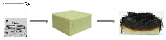
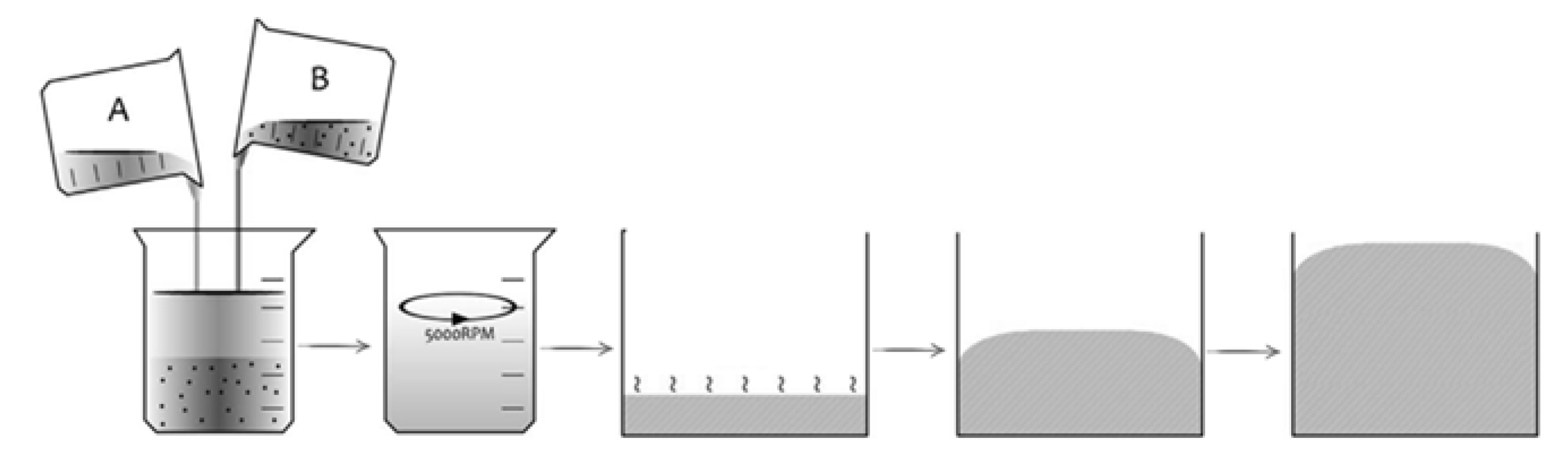
2.1. Materials and Manufacturing

RPUFs were synthesized from a modified polyisocyanurate rigid foam formulation based on petrochemical components provided by Purinova Sp. z o.o. Izopianol 30/10/C (Purinova Sp. z o.o.) used in the reaction is a fully formulated mixture containing a mixture of polyester polyol (hydroxyl number ca. 230–250 mgKOH/g, the functionality of 2), catalyst (N,N-dimethylcyclohexylamine), flame retardant (Tris(2-chloro-1-methylethyl)phosphate) and chain extender (1,2-propanediol). Purocyn B (Purinova Sp. z o. o.) used in the synthesis is a polymeric diphenylmethane 4, 4′-diisocyanate (pMDI) containing 31 wt% of free isocyanate groups. The formulations were modified with expanded graphite [EG] S7 treated with sulfuric acid—(generously donated by the S.Z.T.K. ‘TAPS’—Maciej Kowalski, Poland), fumed silica [SiO2] with a specific surface area of 380 m2/g (Aerosil 380, Evonic Industries) and ionic liquid [IL], 1-ethyl-3-methylimidazolium tetrafluoroborate [emim] [BF4] (Fluka).
Four series of foams were made. The first reference series without the addition of a modifier and 3 with modifiers. Both graphite and silica were added based on the weight of the polyol, while the ionic liquid was added based on the weight of the silica. The compositions of RPUFs are presented in Table 1.
All RPUFs were prepared in a plastic container. An adequate amount of fillers (EG/SiO2/IL) were added to the polyol and the mixture (labeled as a component A) was mixed with the stirrer at 800 RPM for 60 s. Then, the isocyanate (labeled as a component B) was added to component A and the formulation was mixed at 2000 RPM for 10 s. The PU mixture was poured into an open mold and allowed to expand freely in the vertical direction. All PU foams were conditioned at room temperature for 24 h. A schematic procedure of synthesis of RPUF is presented in Figure 1.

2.2. Characterization Techniques

The absolute viscosities of polyol and isocyanate were determined corresponding to ASTM D2930 (equivalent to ISO 2555) using a rotary viscometer DVII+ (Brookfield, Lorch, Germany). The torque of samples was measured as a range of shear rate from 0.5 to 100 s−1 in ambient temperature.
The structure and size distribution of the foam cells was examined on the basis of the images of the cell structure of the foam, made with the Leica MZ6 optical microscope at two magnifications: 50x and 250x and the JEOL JSM-5500 LV scanning electron microscopy (JEOL, Ltd., Peabody, MA, USA). All microscopic observations were made in high vacuum mode and with an accelerating voltage of 10 kV. The samples were scanned for free growth. Mean pore diameter, wall thickness and pore size distribution were calculated with ImageJ software (Media Cybernetics, Inc., Rockville, MD, USA).
The apparent density of foams (5 specimens per sample were measured and averaged) was determined accordingly to ASTM D1622 (equivalent to ISO 845).
The compressive strength (σ10%) of foams (averaged 5 measurements per each sample) was determined accordingly to the ASTM D1621 (equivalent to ISO 844) using Zwick Z100 Testing Machine (Zwick/Roell Group, Poland, Łódź). The compression strength was measured as a ratio of the load causing a 10% deformation of sample cross-section in the parallel and perpendicular direction to the square surface.
A three-point bending test was carried out using Zwick Z100 Testing Machine (Zwick/Roell Group, Ulm, Germany) at room temperature, according to ASTM D7264 (equivalent to ISO 178). The obtained flexural stress at break (εf) results for each sample were expressed as a mean value. The average of 5 measurements per each type of composition was accepted.
The thermal conductivity of the foams obtained was determined based on the measurement of the thermal conductivity (λ). The test was carried out for 200 × 200 × 50 mm3 samples using a FOX 200 apparatus (LaserComp, Inc., Saugus, MA, USA). Thermal conductivity was determined at 10 and 20 °C in the range from 20 to 100 mW/(m*K).
The fire behavior was analyzed using a cone calorimeter apparatus according to ISO 5660 in S.Z.T.K. ‘TAPS’—Maciej Kowalski Company (Tarnowo Podgorne, Poland). Each specimen with dimensions of 100 × 100 × 50 mm3 was wrapped with aluminum foil and burned at an external heat flux of 35 kW m−2. The parameters were recorded during the time. The measurement for each specimen was repeated three times, and the error values of the typical cone calorimeter were reproducible within ±5%, and the reported results are the average of three measurements.
The thermal stability testing of rigid polyurethane foams was performed using a Mettler Toledo thermogravimetric analyzer TGA/DSC1. Thermal decomposition was carried out in the range of 25–600 °C in an inert gas atmosphere with a flow of 50 mL/min and a heating rate of 10 °C/min. The measurement consists of analyzing the change in mass as a function of temperature during the thermal decomposition of the sample. The initial decomposition temperatures, T5%, T10%, T50%, and T70% of mass loss were determined.

3. Results and Discussion

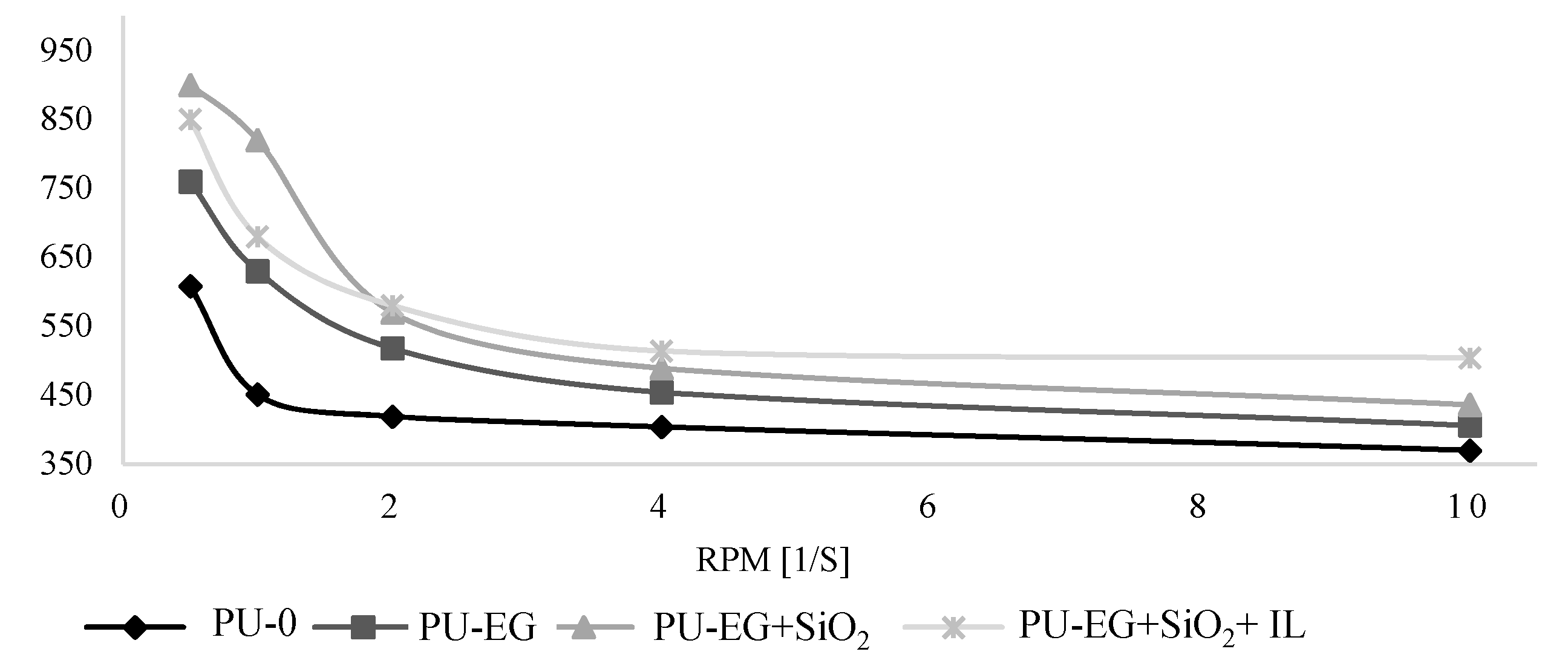
3.1. Rheological Properties of the Polyol Premixes

The factors determining the course of synthesis—including foaming, and RPUR processing—is the viscosity of the polyol blends. Therefore, the influence of all additives on the dynamic viscosity of the polyol was investigated.
Based on the obtained data, a graph of the dynamic change in viscosity as a function of shear was prepared for the tested polyol mixtures. In Figure 2, it can be seen that the addition of solids increases the viscosity of the system, which may also indicate the reactivity of the modifiers towards the polyol. Moreover, the dependence of the decrease in viscosity of the polyol mixtures as a function of the increasing shear rate is clearly visible, especially in the initial phase, when the shear rates are not high. The observed tendency indicates that the tested mixtures are typical for non-Newtonian shear thinned liquids. The addition of IL reduces the dynamic viscosity of the polyol due to the addition of graphite and silica. However, with increasing shear rate, the viscosity for this system decreases the least, and above 2 PRM the highest values are obtained.
A similar trend of increase in polyol viscosity due to the addition of solid modifiers was also observed in previous studies [14,15,16].

3.2. Growth Kinetics of PU Systems

Foaming behavior was determined by measuring temperature and processing time—start, growth and tack-free time.
The reaction of the synthesis of rigid polyurethane foams is classified as highly exothermic, during which large amounts of heat are released. Based on the growth rate of the foams and the temperature during RPUF synthesis, the reactivity of the polyol-isocyanate system can be determined. Analyzing the obtained results, it can be easily seen that for all modified samples the maximum temperature was decreased during the synthesis. The effect of the addition of expanded graphite on the maximum temperature is very visible and additionally intensified by the addition of silica and ionic liquid. Thanks to its very good thermal conductivity, EG has the ability to dissipate part of the heat generated during synthesis to the outside of the foam, which is manifested by a reduction in the maximum temperature of RPUF synthesis. In turn, a further decrease in the temperature of modified systems is associated with the introduction of further fillers containing additional groups that react with isocyanate, leading to side reactions, which release less heat than in the case of polyurethane bond synthesis.
The characteristic times in Table 2 indicate that the addition of fillers increases the foam start and rise times. This is most likely due to the formation of additional nucleation centers, such as active solid filler particles. This consequently leads to increased bubble formation and to an extended start and rise time. Increased viscosity of mixtures containing solid fillers also inhibits further bubble growth, which significantly determines the foam behavior and extends the synthesis time. Moreover, the rate of PU polymerization itself is slowed down due to the presence of fillers which limit the mobility of the molecules leading to phase separation and an increase in the isocyanate conversion time during the reaction. Despite the fact that the addition of graphite, silica and ionic liquid affects the processing time, the total preparation time of PU foams is still within the permissible operating conditions [17,18]. The presented results are consistent with other materials described in the literature.

3.3. Apparent Density of RPUFs

The apparent density is a parameter that determines the physical properties of foams. It is closely related to such foam properties as dimensional stability, thermal insulation as well as all mechanical properties. By analyzing the results presented in Table 3, it can be stated that for all tested foams, the apparent density increased from 41 kg/m3 for the reference foam to a maximum value of 48 kg/m3 for the series containing graphite and silica. The increase in apparent density is the result of increased system viscosity, hindered expansion of bubbles, as well as an additional mass of fillers with higher densities compared to the PU matrix.

3.4. Morphology of RPUFs

Figure 3 shows the structure parameters of RPUF obtained using an optical microscope. As shown in Figure 3a, the unmodified foam has a high regularity of the porous structure for which no cell elongation in the direction of foam growth was observed. Their diameter is about 0.47 mm. Moreover, the rib structures separating individual pores are visible. They are characterized by a fairly large thickness, which indicates good stability of the entire structure. The photo also shows that standard foam has a high percentage of closed-cell cells. The structure of the RPUF modified with EG is shown in Figure 3b. It was noticeable that the inclusion of a modifying additive caused less uniformity of RPUF structure. The structure of RPUF with the addition of EG was more heterogeneous, with a simultaneous increase in the number of damaged cells. A similar phenomenon was visible for PU foams with the addition of EG+SiO2 (Figure 3c) and EG+SiO2+IL (Figure 3d), in which the structure was more irregular and damaged or defective cells were visible. In addition, the incorporation of fillers reduced the porosity of PU foams. As shown in Table 3, the total porosity of PU–0 was about 91%, while the porosity of modified RPUFs was slightly reduced and depended on the type of filler was in the range 81–83%. Moreover, the modified foams were characterized by a higher anisotropy coefficient due to the higher viscosity of the modified systems and the more heterogeneous structure of the obtained foams. Summing up the analysis of pore size and surface structure of synthesized foams, it could be stated that the addition of selected modifiers significantly affects the morphology of the obtained RPUFs. The degree of cell opening depends on many factors—and among them—the viscosity of the reaction mixture, as well as its reactivity, was of great importance. If the increasing viscosity of the reaction mixture was not properly correlated with the increase in bubbles, they break and consequently open pores form. The more irregular structure and elongation in the direction of growth of modified foams relative to the reference foam were due to the nature of the reactions taking place, which were more violent by increasing the reactivity of the system [19].

3.5. Mechanical Properties of RPUFs

Cell morphology is a very important factor that translates into the later properties of RPUF. The close correlation with the structure is the apparent density of PU foam, which is one of the most important parameters describing porous materials. It is directly related to such foam properties as dimensional stability, thermal insulation as well as all mechanical properties. By analyzing the results presented in Table 3. It can be stated that for all tested foams the apparent density increased from 41 kg/m3 for PU–0 foam to a maximum value of over 47 kg/m3 for the series containing EG and Si. The increase in density in modified systems was the result of increased system viscosity, impeded bubble expansion, as well as the additional mass of fillers with specific densities. The addition of modifiers also increased the hardness of RPUF, which was the result of increased apparent density, because the higher the apparent density of the composite, the more compact it was and thus the higher the hardness. In addition, the presence of reinforcing fillers in the form of expanded graphite and silica capable of creating secondary structure and for polymer–filler interactions, increasing the hardness of synthesized foams.
Due to cell anisotropy, the compressive strength (σ10%) was measured in two directions: parallel and perpendicular to the foam growth direction. As shown in Table 3, the compressive strength (measured in parallel and perpendicular direction) of modified foams was higher than σ10% PU–0.
The results distinctly point out that there is a correlation between σ10% and the density of RPUFs. Samples with higher density had higher values of σ10%. In addition, it was seen that the mechanical strength of rigid polyurethane foams—measured in a direction perpendicular to the growth of the foam—was greater than in the parallel, which was associated with cellular anisotropy manifested in the cell lengthening in the direction of foam growth. The reference foam had a resistance of 162 kPa, which was the minimum compressive strength value declared by PUR manufacturers. In the case of modified foams, a tendency to increase mechanical strength was visible along with the introduction of another modifier. The addition of EG and SiO2 had a positive effect on increasing the compressive strength up to a maximum value of 261 kPa. This value was over 60% higher than in the case of PU–0 foam. The improvement in σ10% for modified foams may be due to the increased content of polar urea groups that can form hydrogen bonds and stiffen the structure. Undoubtedly, the tested mechanical properties were also affected by the increasing viscosity of the systems together with the increase in the content of modifiers that could more stabilize the structure of the resulting foam. An analogous improvement in properties could also be seen in the measurement of impact strength and flexural strength of modified PU foams.
This reinforcing effect could also be explained by the mechanism for introducing fillers into the matrix of porous material. Namely, the filler particles, which due to interfacial adhesion were located in the cell struts of the polyurethane matrix, could disperse and transfer stress, which increased the resistance to mechanical stress. A similar trend was also seen in previous studies [20,21,22,23].

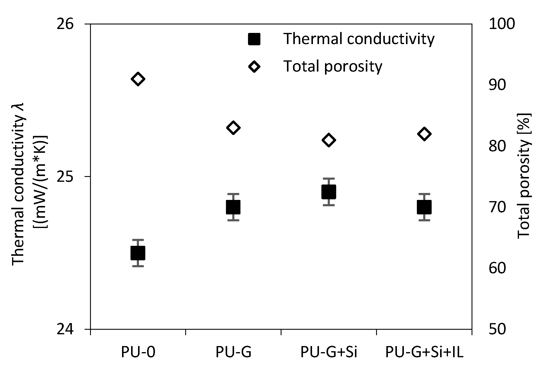
3.6. Thermal Conductivity of PU Foams

Low thermal conductivity (λ) is a key parameter indicating the use of rigid polyurethane foams as insulation materials in construction. The value of thermal conductivity is the result of several factors, namely: apparent density, number of closed cells and cell size [24,25]. To investigate the effect of used modifiers on the insulating properties of PU foams, the value of thermal conductivity was measured at 10 and 20 °C.
The results in Table 4, shows that as a result of the introduction of modifiers, the heat transfer coefficient changes. This was the result of a change in the foam structure due to the addition of additives, which was manifested in a change in foam density and porosity. It could be seen that as the amount of modifiers increased, the density and therefore the thermal conductivity coefficient increased (Figure 4 and Figure 5).
This is because the value of the thermal conductivity coefficient depends on the share of individual phases and their thermal conductivity. The skeleton has a much higher thermal conductivity than the gas component, so the greater the proportion of the skeleton, the greater the thermal conductivity of the porous composite. The increase in thermal conductivity caused by the introduction of a large amount of solid fillers of both organic and inorganic nature is widely described in the literature. Kurańska et al. [26] showed that despite the high content of closed cells, the thermal conductivity coefficient increased for samples modified with basalt waste in the amount of 3–40% by weight. In turn, Modesti et al. [27] showed the effect of expanded flake aggregates as carriers for heat transport through the solid material, which resulted in increased thermal conductivity. Nevertheless, the value of thermal conductivity (about 0.025 (mW/(m*K)) is in the range that is acceptable from an application point of view [28]. A similar relationship was also observed in the case of our study.

3.7. Fire Behavior of RPUFs

The flame retardant behavior of RPUFs was determined using a cone calorimeter test, which is recognized as the best method to simulate small-scale fire conditions. The results of ignition time (TTI), peak heat release rate (pHRR), total heat release (THR), the maximum average rate of heat emission (MAHRE) as well as the total smoke release (TSR) and char residue are presented in Table 5.
The cell structure had a great impact on the fire behavior of PU foam; however, the addition of a filler could change it significantly [26]. As can be seen in Table 5, the ignition time (TTI) was increased by the addition of EG and EG with Si and the peak heat release rate (pHRR), total heat release (THR), total smoke release (TSR) decreased with addition each modifier. This phenomenon probably resulted from the effective heat assimilation by expanded graphite and silica, which delay the burning of foams.
The parameter that should be taken into account is the heat release rate—defined by the peak heat release rate, which provides information on the spark ignition of the exposed burned material. Based on the results presented in Table 5, it can be noticed that the addition of the modifiers to the RPUFs decreased the pHRR value compared to the unmodified foam.
Namely, for PU–EG, PU–EG+SiO2 and PU–EG+SiO2+IL samples, the pHRR value was 71, 62 and 64 kW/m−2, respectively, which means a reduction of approximately 67, 71 and 70% compared to reference foam. The decrease in pHRR was due to the fact that the expanded graphite exposed to the heat source expands into the carbonaceous layer on the RPUF surface. The formed char layer effectively hinders the diffusion of oxygen and the transfer of mass and heat between the flames and the polyurethane matrix, thus interrupting the self-sustaining combustion of the foam [29]. The addition of an additional filler, i.e., pyrogenic silica, resulted in the creation of an additional thermal barrier, because in addition to the high thermal stability of silica, it also favored the ceramization process, which further enhanced the barrier effect. In contrast, no positive effect of IL on pHRR was observed. Probably, despite the content of anion [BF4], the ionic liquid decomposed during the combustion process, as evidenced by a slightly lower content of carbonized residues than in the case of PU–EG+SiO2. However, as could be predicted at the end of combustion, RPUFs with addition only EG and EG in the presence of SiO2 or SiO2+IL retained more carbonized residues than PU–0 foam. This trend was comparable to the residual weight obtained from TGA, although the TGA residue was slightly lower compared to the results of the cone calorimeter. This was probably the result of oxidative decomposition which enhances pyrolytic decomposition under forced-flame conditions. As shown in Table 5 the total char residue of the PU–0 sample was about 13.1%, and the addition of flame retardants increased the char yield by up to 31.8% for the PU–EG+SiO2 sample. The increased char yield of PU foams containing expanded graphite may be due to the presence of a protective char layer acting as a swelling, thermal barrier, which contributes to a reduction in the diffusion rate of volatile compounds as well as a significant reduction of oxygen supply to the interior of the sample. As a result of this action, the further distribution of the sample was reduced, and the weight loss of modified foams was less than for a sample without the addition of a graphite flame retardant. It should be noted that for RPUF used as insulation materials the available pHRR value was 300 kW m−2 [30], while for the analyzed PU foams the pHRR values did not exceed 71 kW m−2. In addition, the THR value was obtained much lower for modified foams in comparison with PU–0 foam. The smallest amount of total heat released was obtained for the PU–EG+SiO2 sample, which decreased by over 20% compared to the PU–0 sample. Other modified samples had similar THR values.
The most common cause of death in a fire is smoke, therefore total smoke release (TSR) is very important for the safety and fire resistance assessment of materials. Based on the data contained in Table 5, it can be seen that the use of fillers effectively reduced smoke during the combustion process. All modified PU foams had significantly lower TSR values. For PU–0, the TSR value was about 37.9 m2 m−2 and significantly decreased to 15.6 m2 m−2 for the PU–EG+SiO2 sample, which was probably the result of the formation of a dense carbon layer on the polymer surface, which may limit the total amount of smoke released during the combustion process.
The fire-retardant properties of the test samples can also be well assessed on the basis of the observation of the residual samples after combustion in the calorimetric cone test. Figure 6 shows comparative digital photos of PU–0 and PU–EG residues after the cone calorimeter test. Differences in the appearance of the two samples can be seen, indicating two different combustion mechanisms. In Figure 6a it can be seen that the unmodified PU–0 sample was burned almost to the very end. On the other hand, the photo 6b shows a charred boundary layer that does not let fire into the sample, making the intact part larger than the photo on the left.
To obtain a more detailed structural analysis and determine the mechanism of action of the modifiers used, SEM analysis was performed after the combustion selected samples; the images are presented in Figure 7. By analyzing the following pictures, it can be seen that the microscopic pictures of the tested composites differ from each other. It can be seen that in the case of PU–0, the carbonized residue has a porous structure with broken cells. The PU–0 structure (Figure 7a) had rough characteristics and presents an indistinct “molten” network, without clear cell structure features. In the case of a sample containing expanded graphite, a clear flame retardation mechanism was visible. The pictures (Figure 7b–c) show the characteristic structure in the form of charred ribs between the cells of the porous structure, which prevented the spread of fire into the burning sample.

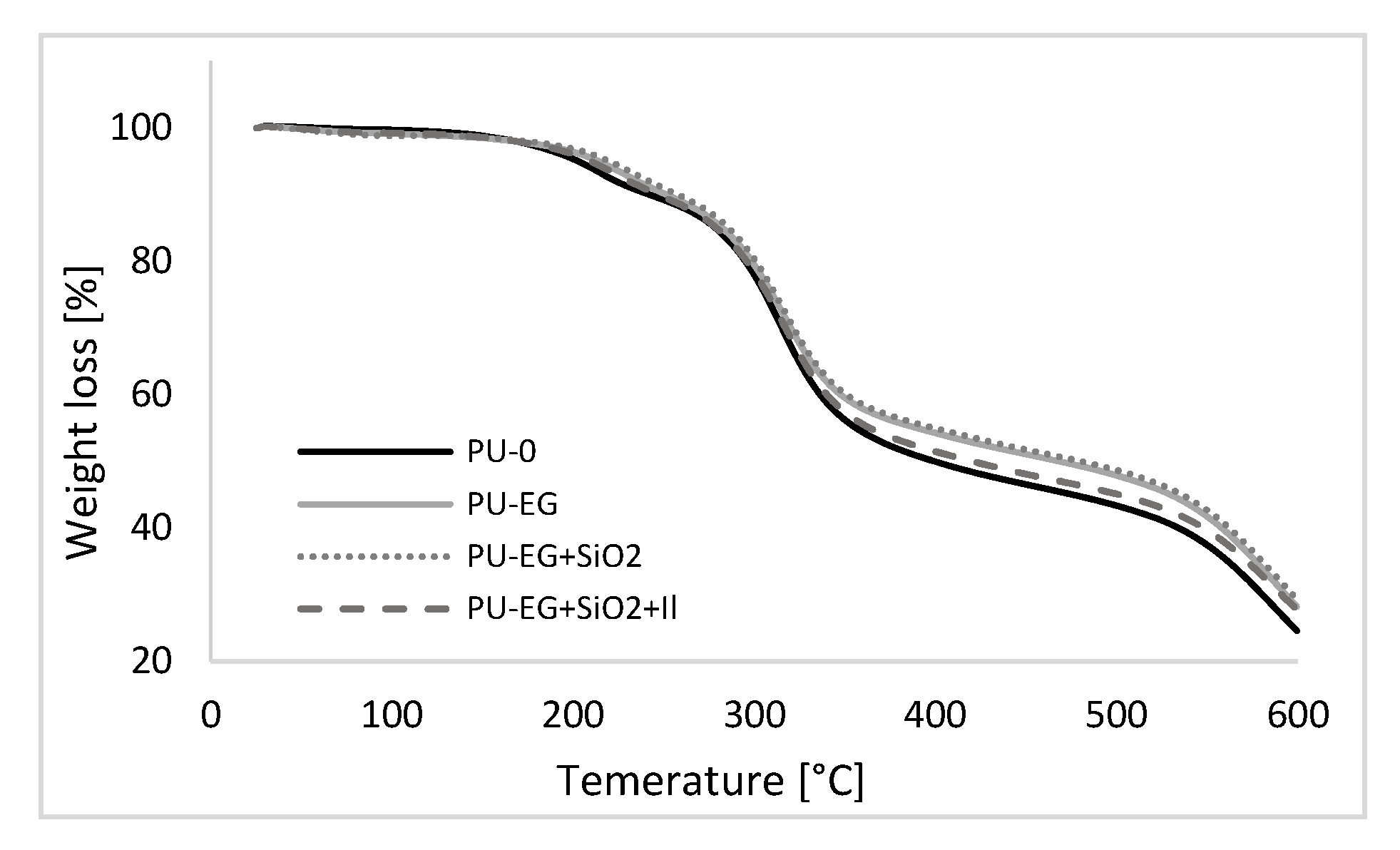
3.8. Thermogravimetric Analysis (TGA) of PU Foams

To better understand the role of EG and silica to the flame-retardant behavior of PU composite, the thermal stability of these composites was studied by TGA. Thermogravimetric analysis (TGA) and differential thermogravimetry (DTG) analysis of neat RPUF (PU–0) and RPUF filled EG and EG with silica or silica in presence IL on–air atmosphere are illustrated in Figure 8 and Figure 9. Table 6 shows the individual temperatures with a specific weight loss, namely 5% (T5%), 10% (T10%), 50% (T50%), 70% (T70%) as well as the char residue at 600 °C.
Thermal degradation of RPUFs took place in three stages. The first stage of decomposition manifested by about 10% loss of initial mass indicated dissociation of urethane bonds occurring at a temperature of 150 to 250 °C. The second degradation stage corresponding to a weight loss of about 50% occurs at a temperature between 250 and 400 °C and is attributed to the distribution of soft polyol segments [29,31]. At this stage, the hydrocarbon chains in PU foam are initially broken down and EG is activated and begins to expand, creating a protective carbon layer and stabilizing the foam surface. EG pyrolysis consists of SO2, CO2 and water that is trapped when escaping near the edge of the graphite structure, which leads to the irreversible expansion of the graphene structure and the formation of a graphite carbonized layer on the foam surface. This layer prevents heat transfer through the solid phase and stops the fire. This effect can be seen when the foam surface expands during combustion [32]. This is followed by the third degradation stage, during which the fragments formed during the second stage are degraded at 500 °C, corresponding to a 70% weight loss [31,33] and is the result of further breakdown of the RPUF structure and charring. At this stage, also other products that come from isocyanate groups (e.g., amines or benzene alkyl) decompose into volatile products (HCN, CO2 or NO2) [34]. Compared to the PU–0 reference foam, foams containing only EG and EG with the addition of Si showed slightly less weight loss, suggesting increased carbon stability. In turn, the ionic liquid did not affect and even reduced the thermal stability of the foams compared to foams containing EG or EG+SiO2, in which the thermal stability of PU foams is observed to increase with increasing temperature.

4. Summary

Based on the analysis of the presented results—including both the synthesis and physicochemical tests of RPUFs—it can be concluded that the synergistic flame retardant system based on expanded graphite with the addition of silica and ionic liquid had a positive effect on the properties of the porous composite. It was observed that the introduction of fillers has a meaningful impact on the structure and further mechanical and thermal properties of RPUFs. Although the addition of graphite expanded alone or in the presence of silica and ionic liquid can interfere with the foam structure and increase apparent density, this can also improve its strength properties. As a result of the introduction of the synergistic system, it was noted that the compressive strength improved by approximately 60% for PU–EG+SiO2 samples compared to the reference sample. Higher three-point bending strength, impact strength, and higher hardness were also observed. The modified RPUFs were characterized by similar values of thermal conductivity and better thermal properties. The RPUFs modification has, above all, a positive effect on the fire resistance of composites. The results showed that the fire resistance of PU foams containing EG and SiO2 is significantly improved, namely the incorporation of expanded graphite and silica significantly reduced the peak heat release rate (pHRR) by about 70% in relation to the reference sample. Based on SEM images, it can be seen that the introduced graphite can form an expansion carbonizing layer during combustion, which can significantly reduce the spread of fire in the foam.

Author Contributions

Conceptualization, A.S.; Methodology, A.S.; Software, A.S.; Validation, A.S., S.C. and P.K.; Formal Analysis, A.S.; Investigation, A.S., S.C. and P.K.; Resources, A.S; Data Curation, A.S; Writing-Original Draft Preparation, A.S; Writing-Review & Editing, K.S.; Visualization, A.S.; Supervision, A.S. All authors have read and agreed to the published version of the manuscript.

Funding

This research received no external funding.

Conflicts of Interest

The authors declare no conflict of interest.

References

  1. Borreguero, A.M.; Velencoso, M.M.; Rodríguez, J.F.; Serrano, A.; Carrero, M.J.; Ramos, M.J. Synthesis of aminophosphonate polyols and polyurethane foams with improved fire retardant properties. J. Appl. Polym. Sci. 2019, 136, 47780. [Google Scholar] [CrossRef]
  2. Xu, W.; Wang, G.; Zheng, X. Research on highly flame-retardant rigid PU foams by combination of nanostructured additives and phosphorus flame retardants. Polym. Degrad. Stab. 2015, 111, 142–150. [Google Scholar] [CrossRef]
  3. Venier, M.; Salamova, A.; Hites, R.A. Halogenated flame retardants in the great lakes environment. Am. Chem. Soc. 2015, 48, 1853–1861. [Google Scholar] [CrossRef] [PubMed] [Green Version]
  4. Prociak, A.; Rokicki, G.; Ryszkowska, J. Materiały Poliuretanowe; Wydawnictwo Naukowe PWN: Warszawa, Poland, 2014; pp. 93–98. [Google Scholar]
  5. Pietruszka, N.; Brzozowski, Z. A new group of liquid reactive nitrogen and nitrogen—Phosphorus flame retardants for self-extinguishing polyurethane expanded polymers. Part I. Synthesis and properties. Polimery 2000, 45, 184–190. [Google Scholar] [CrossRef]
  6. Chen, H.B.; Shen, P.; Chen, M.J.; Zhao, H.B.; Schiraldi, D.A. Highly Efficient Flame Retardant Polyurethane Foam with Alginate/Clay Aerogel Coating. ACS Appl. Mater. Interfaces 2016, 8, 32557–32564. [Google Scholar] [CrossRef]
  7. Ionescu, M. Chemistry and Technology of Polymer for Polyurethanes; Rapra Technology Ltd.: Shawbury, UK, 2008. [Google Scholar]
  8. Yang, F.; Nelson, G.L. Halogen-free flame retardant flexible polyurethane foams via a vombined effect of flame retardants. ACS Symp. Ser. 2012, 1118, 139–149. [Google Scholar]
  9. Camino, G.; Duquesne, S.; Delobe, R.; Eling, B.; Lindsay, C.; Roels, T. Mechanism of expandable graphite fire retardant action in polyurethanes. ACS Symp. Ser. 2001, 797, 90–109. [Google Scholar]
  10. Yuan, Y.; Yang, H.; Yu, B.; Shi, Y.; Wang, W.; Song, L.; Lu, Y.; Zhang, Y. Phosphorus and nitrogen-containing polyols: Synergistic effect on the thermal property and flame retardancy of rigid polyurethane foam composites. Ind. Eng. Chem. Res. 2016, 55, 10813–10822. [Google Scholar] [CrossRef]
  11. Le, H.H.; Das, A.; Basak, S.; Tahir, M.; Wießner, S.; Fischer, D.; Reuter, U.; Stöckelhuber, K.W.; Bhowmick, A.K.; Do, Q.K.; et al. Effect of different ionic liquids on the dispersion and phase selective wetting of carbon nanotubes in rubber blends. Polymer 2016, 105, 284–297. [Google Scholar] [CrossRef]
  12. Subramaniam, K.; Das, A.; Simon, F.; Heinrich, G. Macromolecular nanotechnology networking of ionic liquid modified CNTs in SSBR. Eur. Polym. J. 2013, 49, 345–352. [Google Scholar] [CrossRef]
  13. Subramaniam, K.; Das, A.; Steinhauser, D.; Klüppel, M.; Heinrich, G. Macromolecular nanotechnology effect of ionic liquid on dielectric, mechanical and dynamic mechanical properties of multi-walled carbon nanotubes/polychloroprene rubber composites. Eur. Polym. J. 2011, 47, 2234–2243. [Google Scholar] [CrossRef]
  14. Członka, S.; Bertino, M.F.; Strzelec, K.; Strąkowska, A.; Masłowski, M. Rigid polyurethane foams reinforced with solid waste generated in leather industry. Polym. Test. 2018, 69, 225–237. [Google Scholar] [CrossRef]
  15. Członka, S.; Strąkowska, A.; Strzelec, K.; Kairytė, A.; Vaitkus, S. Composites of rigid polyurethane foams and silica powder filler enhanced with ionic liquid. Polym. Test. 2019, 75, 12–25. [Google Scholar] [CrossRef]
  16. Strąkowska, A.; Członka, S.; Strzelec, K. POSS Compounds as modifiers for rigid polyurethane foams (composites). Polymers 2019, 11, 1092. [Google Scholar] [CrossRef] [PubMed] [Green Version]
  17. John, J.; Bhattacharya, M.; Turner, R.B. Characterization of polyurethane foams from soybean oil. J. Appl. Polym. Sci. 2002, 86, 3097–3107. [Google Scholar] [CrossRef]
  18. Jin, J.F.; Chen, Y.L.; Wang, D.N.; Hu, C.P.; Zhu, S.; Vanoverloop, L.; Randall, D. Structures and physical properties of rigid polyurethane foam prepared with rosin-based polyol. J. Appl. Polym. Sci. 2002, 84, 598–604. [Google Scholar] [CrossRef]
  19. Gu, R.; Khazabi, M.; Sain, M. Fiber reinforced soy-based polyurethane spray foam insulation. Part 2: Thermal and mechanical properties. BioResources 2011, 6, 3775–3790. [Google Scholar]
  20. Verdejo, R.; Stämpfli, R.; Alvarez-Lainez, M.; Mourad, S.; Rodriguez-Perez, M.A.; Brühwiler, P.A.; Shaffer, M. Enhanced acoustic damping in flexible polyurethane foams filled with carbon nanotubes. Compos. Sci. Technol. 2009, 69, 1564–1569. [Google Scholar] [CrossRef]
  21. Maharsia, R.R.; Jerro, H.D. Enhancing tensile strength and toughness in syntactic foams through nanoclay reinforcement. Mater. Sci. Eng. A 2007, 454, 416–422. [Google Scholar] [CrossRef]
  22. Saint-Michel, F.; Chazeau, L.; Cavaillé, J.-Y.; Chabert, E. Mechanical properties of high density polyurethane foams: I. Effect of the density. Compos. Sci. Technol. 2006, 66, 2700–2708. [Google Scholar] [CrossRef]
  23. Nazeran, N.; Moghaddas, J. Synthesis and characterization of silica aerogel reinforced rigid polyurethane foam for thermal insulation application. J. Non. Cryst. Solids 2017, 461, 1–11. [Google Scholar] [CrossRef]
  24. Fan, H.; Tekeei, A.; Suppes, G.J.; Hsieh, F.-H. Rigid polyurethane foams made from high viscosity soy-polyols. J. Appl. Polym. Sci. 2013, 127, 1623–1629. [Google Scholar] [CrossRef]
  25. Mosiewicki, M.A.; Dell’Arciprete, G.A.; Aranguren, M.I.; Marcovich, N.E. Polyurethane foams obtained from castor oil-based polyol and filled with wood flour. J. Compos. Mater. 2009, 43, 3057–3072. [Google Scholar] [CrossRef]
  26. Kurańska, M.; Barczewski, M.; Uram, K.; Lewandowski, K.; Prociak, A.; Michałowski, S. Basalt waste management in the production of highly effective porous polyurethane composites for thermal insulating applications. Polym. Test. 2019, 76, 90–100. [Google Scholar] [CrossRef]
  27. Modesti, M.; Lorenzetti, A.; Simioni, F.; Camino, G. Expandable graphite as an intumescent flame retardant in polyisocyanurate–polyurethane foams. Polym. Degrad. Stab. 2002, 77, 195–202. [Google Scholar] [CrossRef]
  28. Janik, H.; Sienkiewicz, M.; Kucińska-Lipka, J. Polyurethanes. In Handbook of Thermoset Plastics; William Andrew: San Diego, CA, USA, 2014; pp. 253–295. [Google Scholar]
  29. Thi, N.H.; Pham, D.L.; Hanh, N.T.; Oanh, H.T.; Duong, T.H.Y.; Nguyen, T.N.; Tuyen, N.D.; Phan, D.L.; Trinh, H.T.; Nguyen, H.T.; et al. Influence of Organoclay on the Flame Retardancy and Thermal Insulation Property of Expandable Graphite/Polyurethane Foam. J. Chem. 2019. [Google Scholar] [CrossRef]
  30. Qian, L.; Feng, F.; Tang, S. Bi-phase flame-retardant effect of hexa-phenoxy-cyclotriphosphazene on rigid polyurethane foams containing expandable graphite. Polymer 2014, 55, 95–101. [Google Scholar] [CrossRef]
  31. Jiao, L.; Xiao, H.; Wang, Q.; Sun, J. Thermal degradation characteristics of rigid polyurethane foam and the volatile products analysis with TG-FTIR-MS. Polym. Degrad. Stab. 2013, 98, 2687–2696. [Google Scholar] [CrossRef]
  32. Levchik, S.V.; Weil, E.D. Thermal decomposition, combustion and fire-retardancy of polyurethanes—A review of the recent literature. Polym. Int. 2004, 53, 1585–1610. [Google Scholar] [CrossRef]
  33. Septevani, A.A.; Evans, D.A.C.; Chaleat, C.; Martin, D.J.; Annamalai, P.K. A systematic study substituting polyether polyol with palm kernel oil based polyester polyol in rigid polyurethane foam. Ind. Crops Prod. 2015, 66, 16–26. [Google Scholar] [CrossRef]
  34. Acuña, P.; Li, Z.; Santiago-Calvo, M.; Villafañe, F. Influence of the Characteristics of Expandable Graphite on the Morphology, Thermal Properties, Fire Behaviour and Compression Performance of a Rigid Polyurethane Foam. Polymers 2019, 11, 168. [Google Scholar] [CrossRef] [PubMed] [Green Version]
Figure 1. Scheme for drawing-up the RPUF.
Applsci 10 05817 g001
Figure 2. Viscosity of the polyol system modified with graphite, silica and ionic liquid.
Applsci 10 05817 g002
Figure 3. Images of foam using 250× magnification. (a) PU–0; (b) PU–EG; (c) PU–EG+SiO2; (d) PU–EG+SiO2+IL.
Applsci 10 05817 g003
Figure 4. Dependence of the thermal conductivity coefficient at 20 °C on the apparent density of PU foams.
Applsci 10 05817 g004
Figure 5. Dependence of the thermal conductivity coefficient at 20 °C on the total porosity of PU foams.
Applsci 10 05817 g005
Figure 6. Digital images. (a) PU–0; (b) PU–EG after cone calorimeter test.
Applsci 10 05817 g006
Figure 7. SEM images of char residues. (a) PU–0; (b) PU–EG; (c) PU–EG+SiO2.
Applsci 10 05817 g007
Figure 8. TGA graph plotted for PU foams.
Applsci 10 05817 g008
Figure 9. DTG graph plotted for PU foams.
Applsci 10 05817 g009
Table 1. Formulations of rigid polyurethane foams (RPUF) prepared in the study.
Sample
Codes
CommentsMass Content (by Weight, wt% )
PolyolIsocyanateExpanded GraphiteFumed SilicaIonic Liquid (emim) (BF4)
PU–0Reference foam (unfilled)100160---
PU–EGFoam with graphite1001605--
PU–EG+SiO2Foam with graphite and silica10016051-
PU–EG+SiO2+ILFoam with graphite, silica and ionic liquid100160510.33
Table 2. Growth kinetics and structure parameters of RPUFs.
SystemTmax [°C] Processing Times [s] Cell Size [µm]Wall Thickness [µm]Total Porosity [% ]Apparent Density [kg m−3]
StartRiseGelling
PU–014049 ± 3262 ± 8448 ± 14472 ± 1062 ± 49141
PU–EG13456 ± 4277 ± 8498 ± 13296 ± 767 ± 38346
PU–EG+SiO213354 ± 3338 ± 9564 ± 11282 ± 769 ± 38148
PU–EG+SiO2+IL13258 ± 4342 ± 8594 ± 12304 ± 871 ± 48247
Table 3. Mechanical properties of PU foams.
SystemApparent Density
(kg m−3)
Hardness
(°Sh)
Compressive Strength (Parallel)
(kPa)
Compressive Strength (Perpendicular)
(kPa)
Flexural Strength
(MPa)
Impact Strength (kJ/m2)
PU–041.167.61621220.41141
PU–EG45.774.72431530.51227
PU–EG+SiO247.375.62611640.49222
PU–EG+SiO2+IL46.474.42581630.46215
Table 4. Thermal conductivity coefficient at a temperature difference of 10 °C.
SystemThermal Conductivity λ (mW/(m*K)
10 °C20 °C
PU–023.824.5
PU–EG23.424.8
PU–EG+SiO223.624.9
PU–EG+SiO2+IL24.025.3
Table 5. Parameters determined during the combustion process of RPUFs.
SystemTTI (s)pHRR (kW/m2)THR (MJ/m2)MAHRE (kW/m2)TSR (m2/m2)Char Residue (%)
PU–0221321.9180.037.913.1
PU–EG47117.970.816.128.7
PU–EG+SiO256217.261.715.631.8
PU–EG+SiO2+IL56417.763.916.327.6
Table 6. Results of the thermogravimetric analysis of PU foams.
SystemT5%T10%T50%T70%Char Residue
(°C)(°C)(°C)(°C)(%)
PU–020224139958023.4
PU–EG21325046759228.3
PU–EG+SiO221925748059829.4
PU–EG+SiO2+IL20924742059127.8

