Thermomechanically Induced Precipitation in High-Performance Ferritic (HiperFer) Stainless Steels


Abstract
Featured Application
Abstract
1. Introduction
2. Materials and Methods
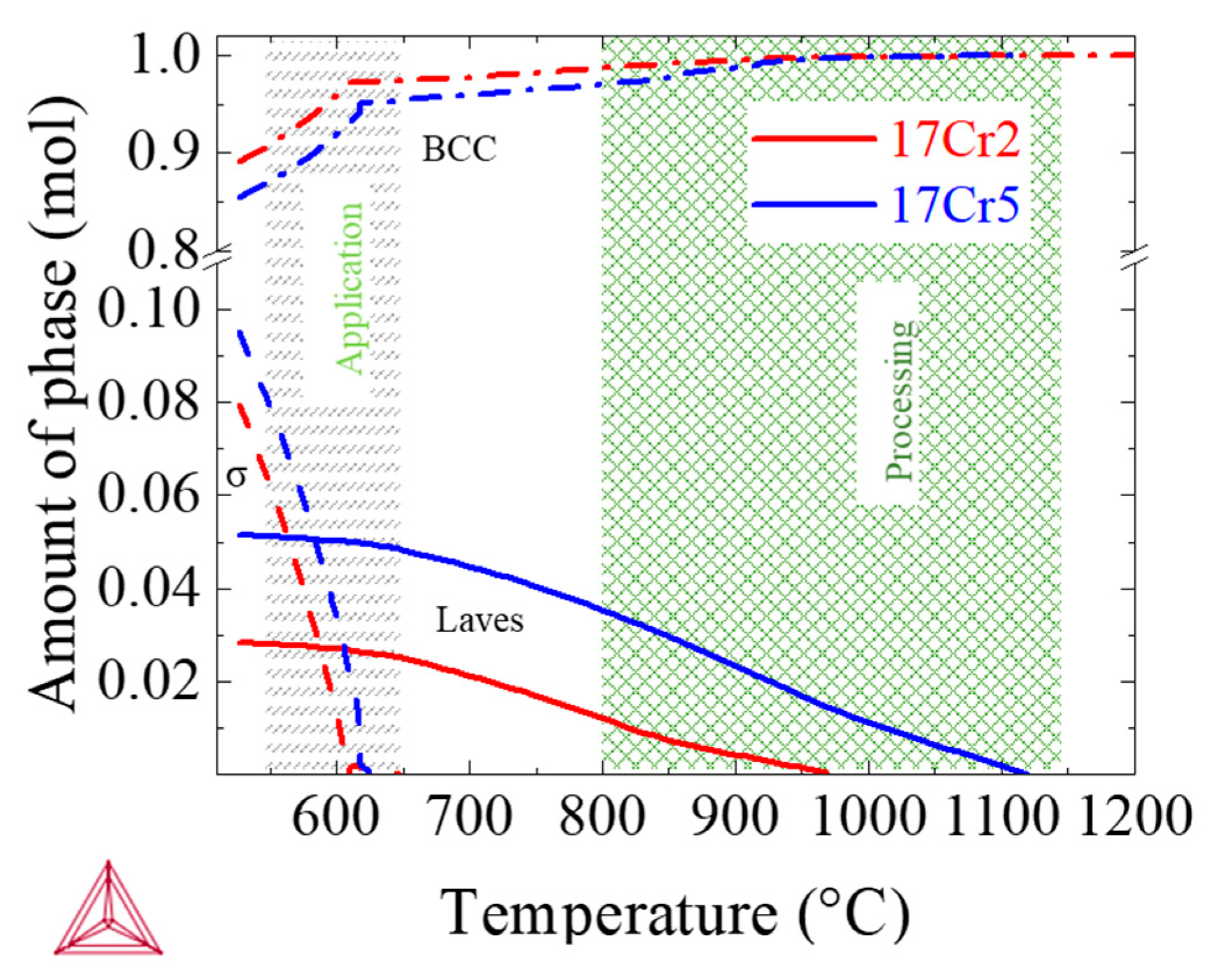
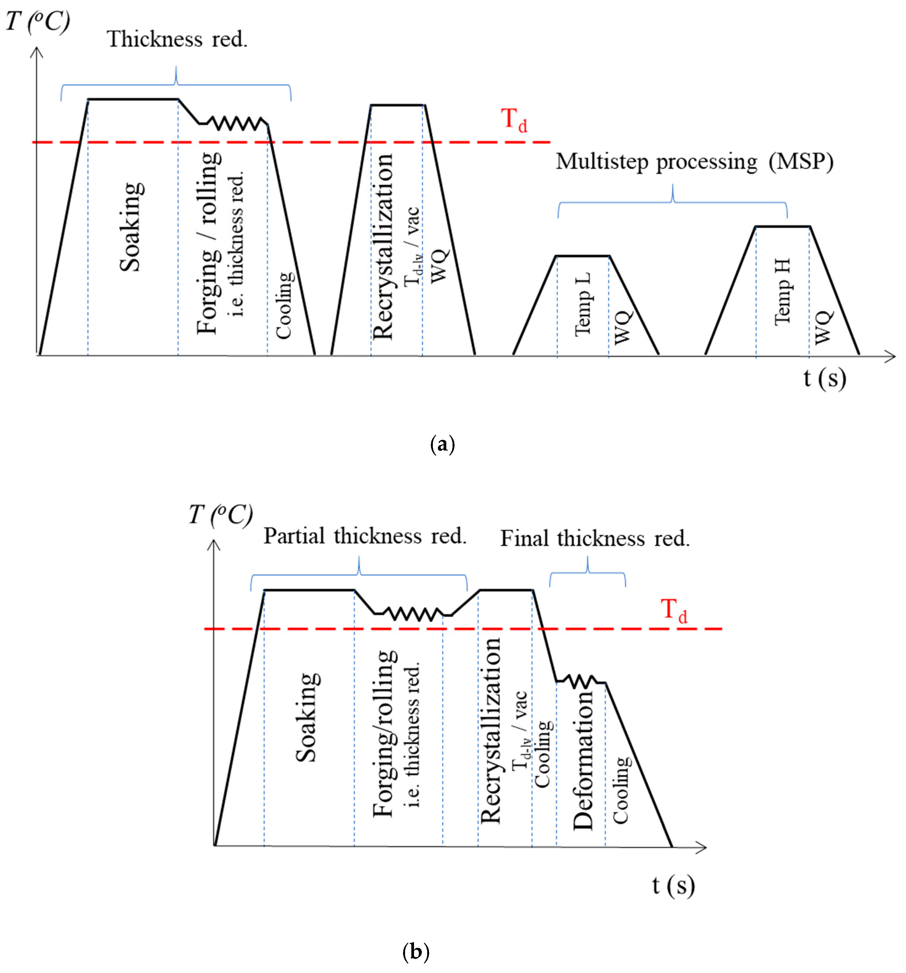
2.1. Alloy Production and Processing
2.2. Microstructure Observation
2.3. Mechanical Testing
3. Results and Discussion
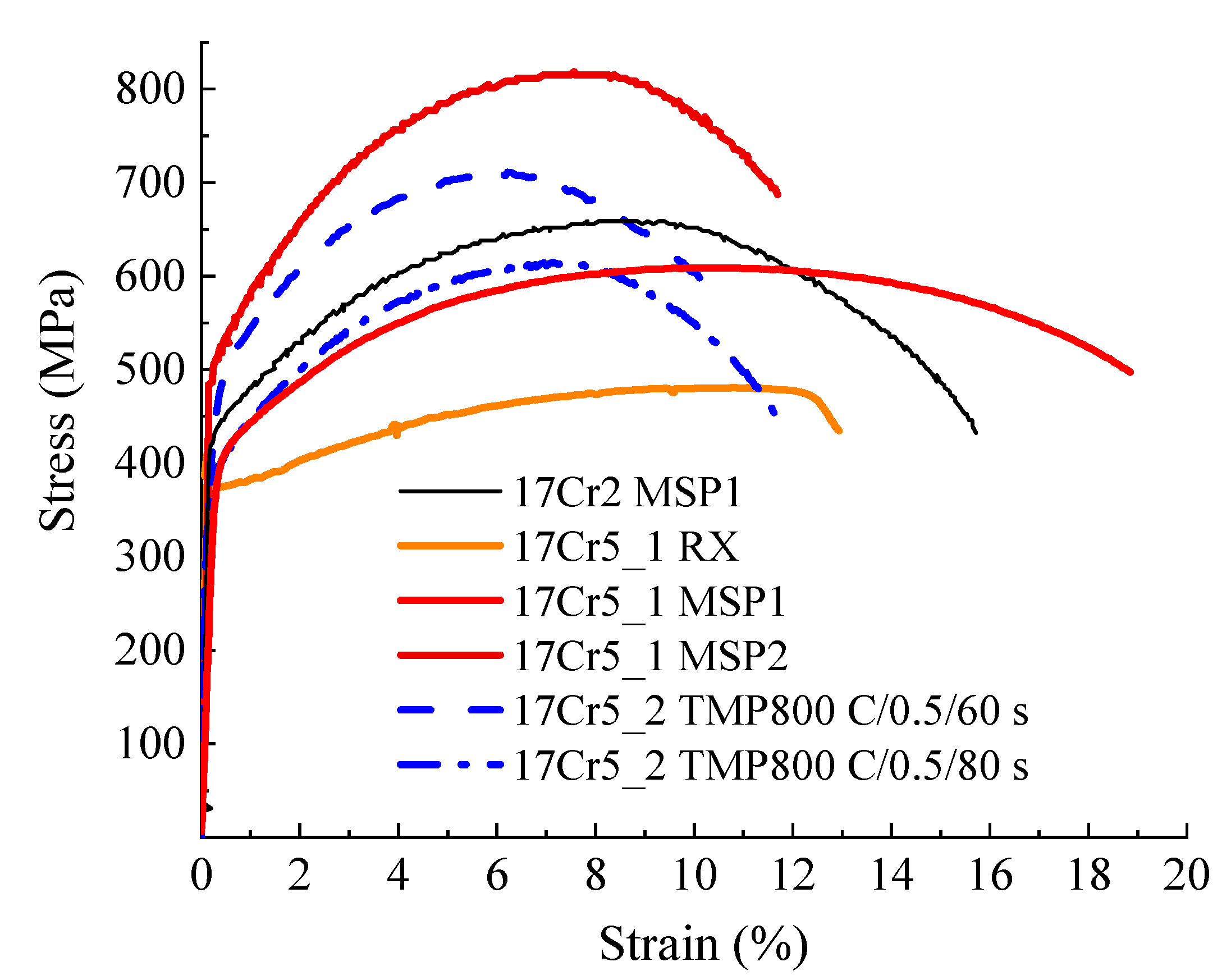
3.1. Mechanical Testing
3.2. Impact of Deformation Parameter Variation
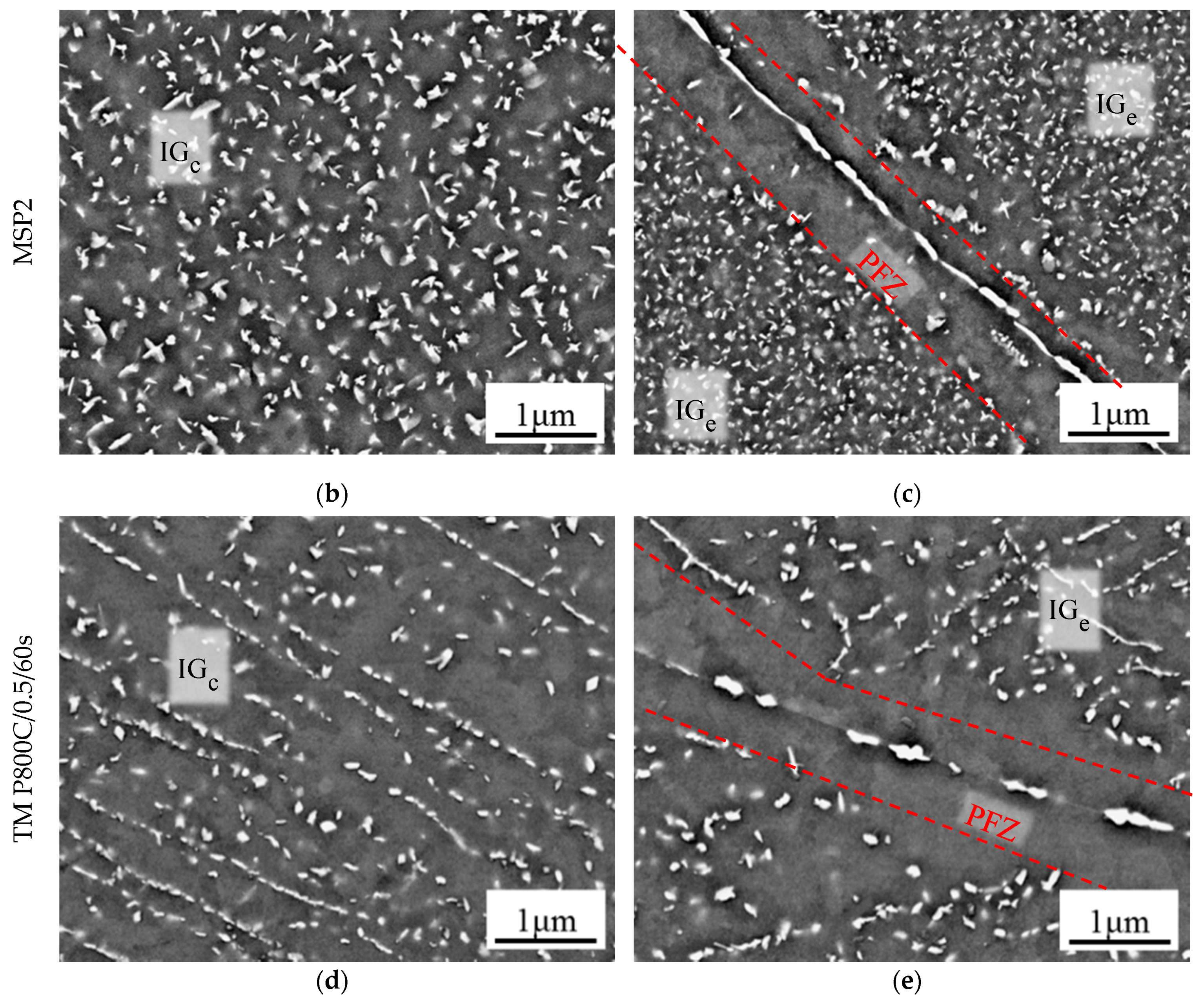
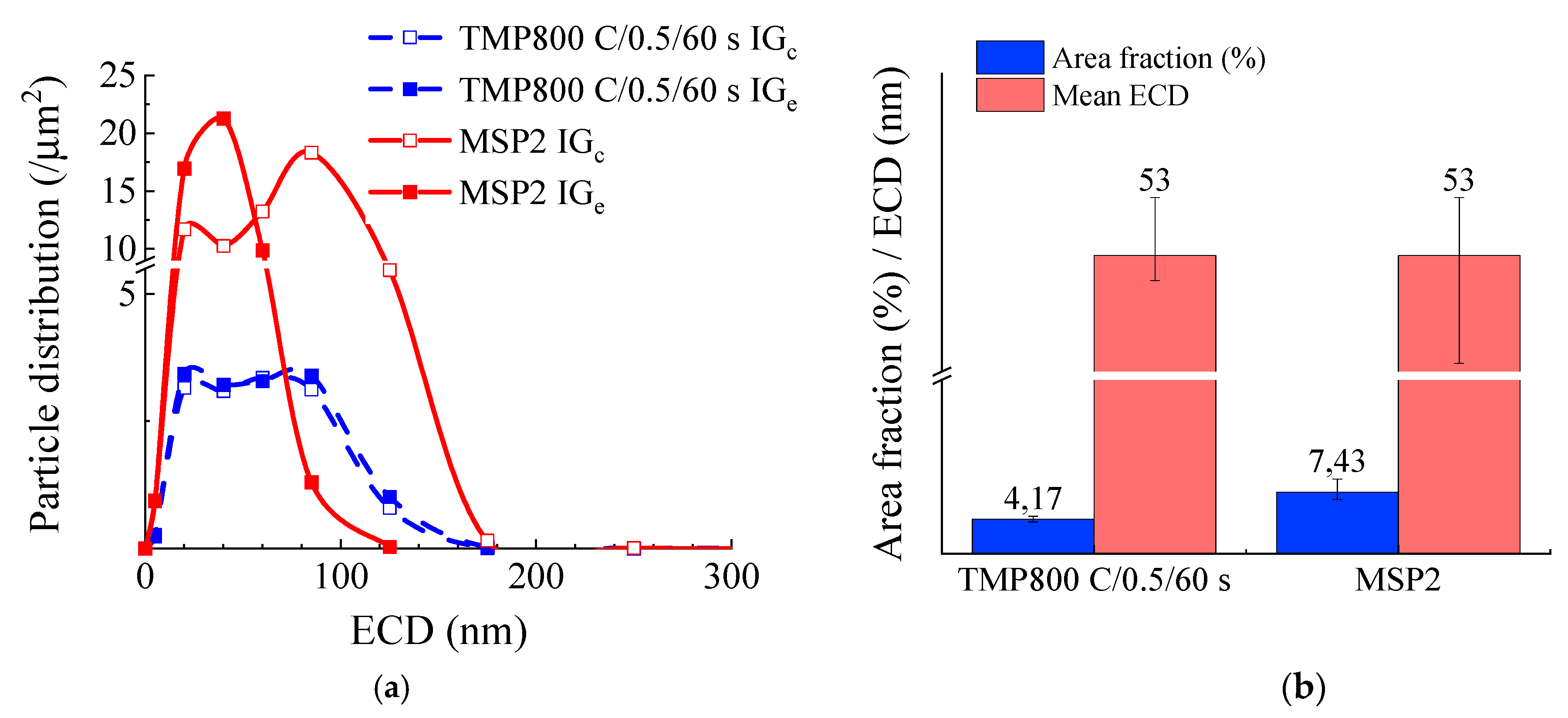
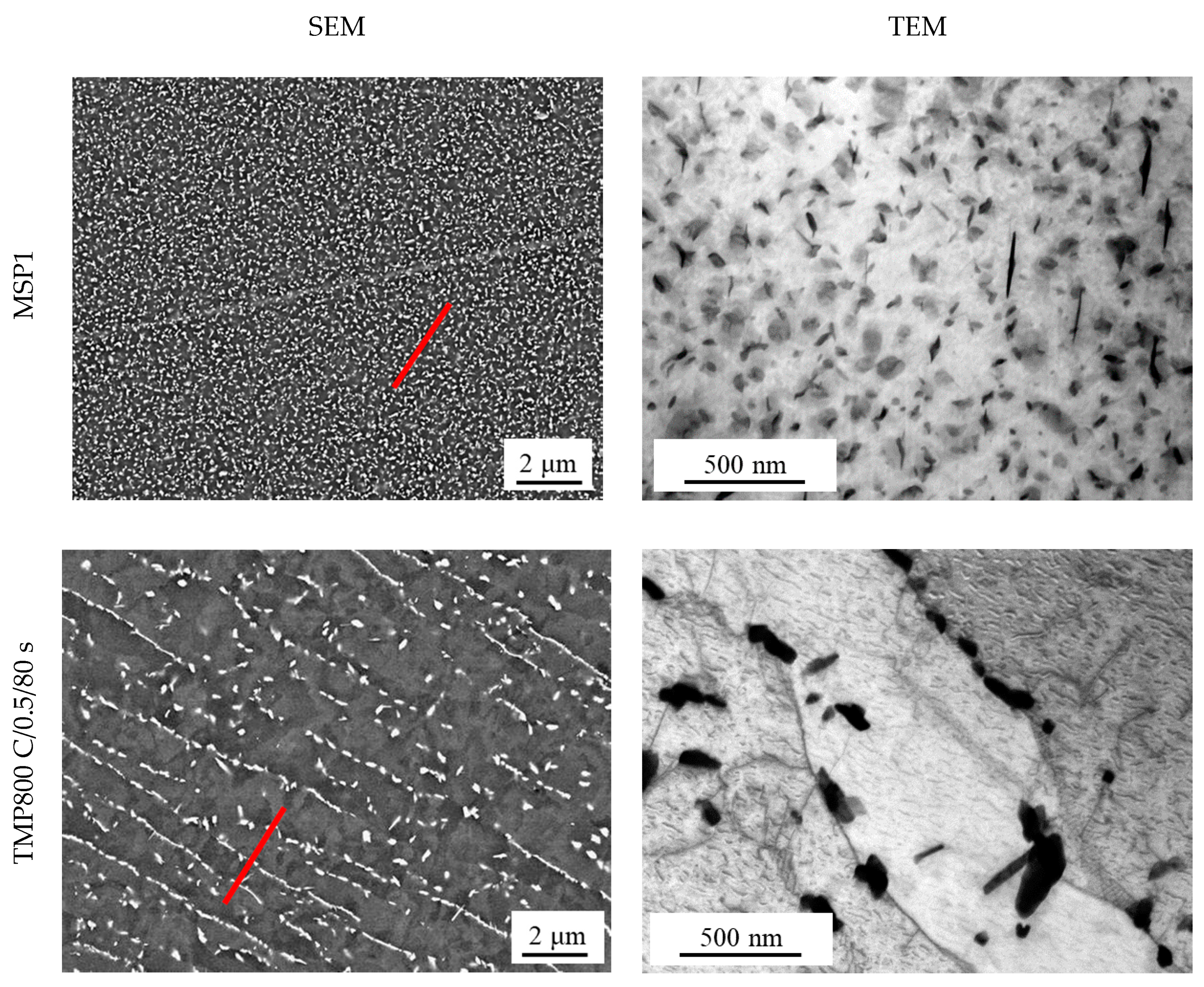
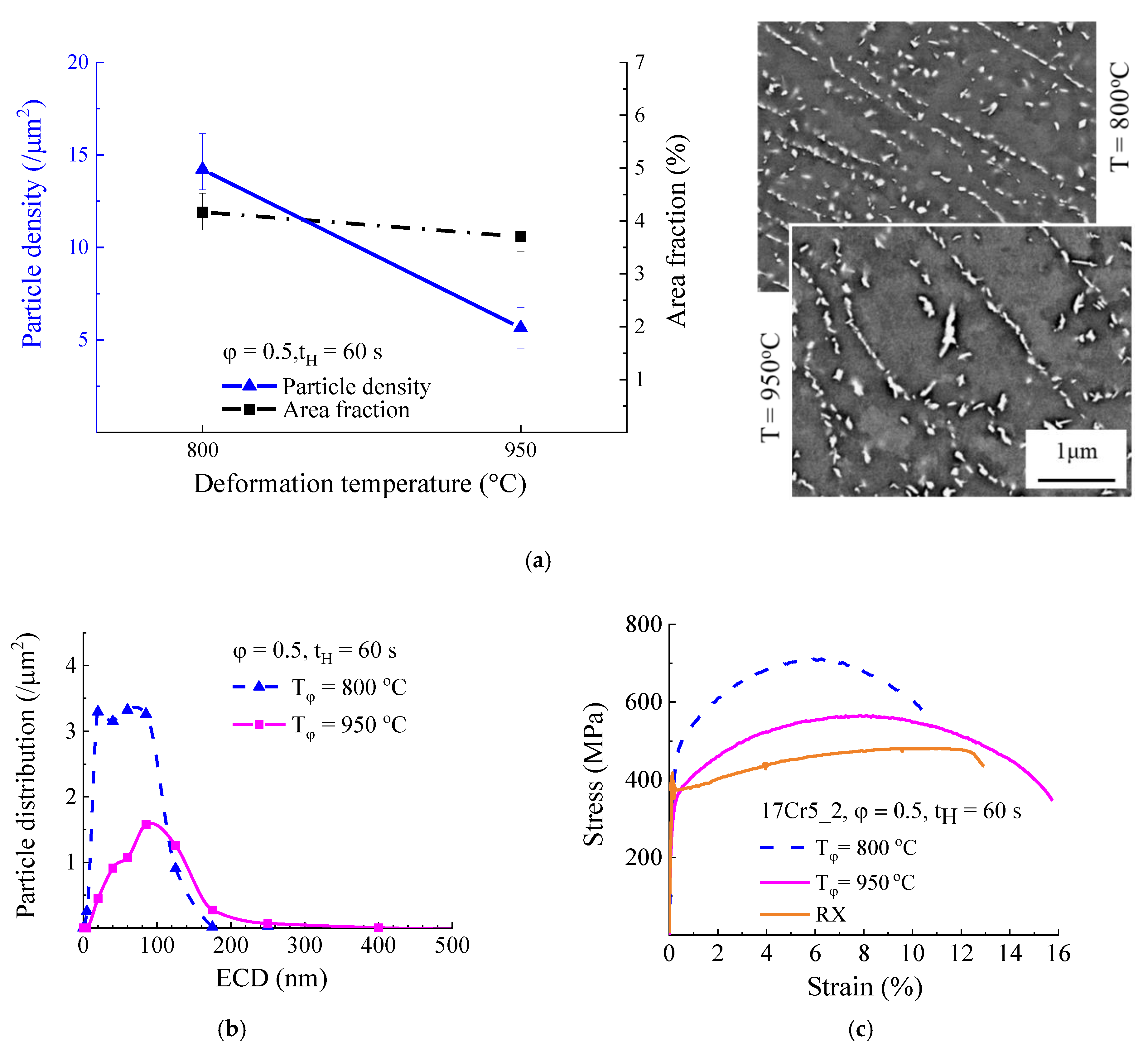
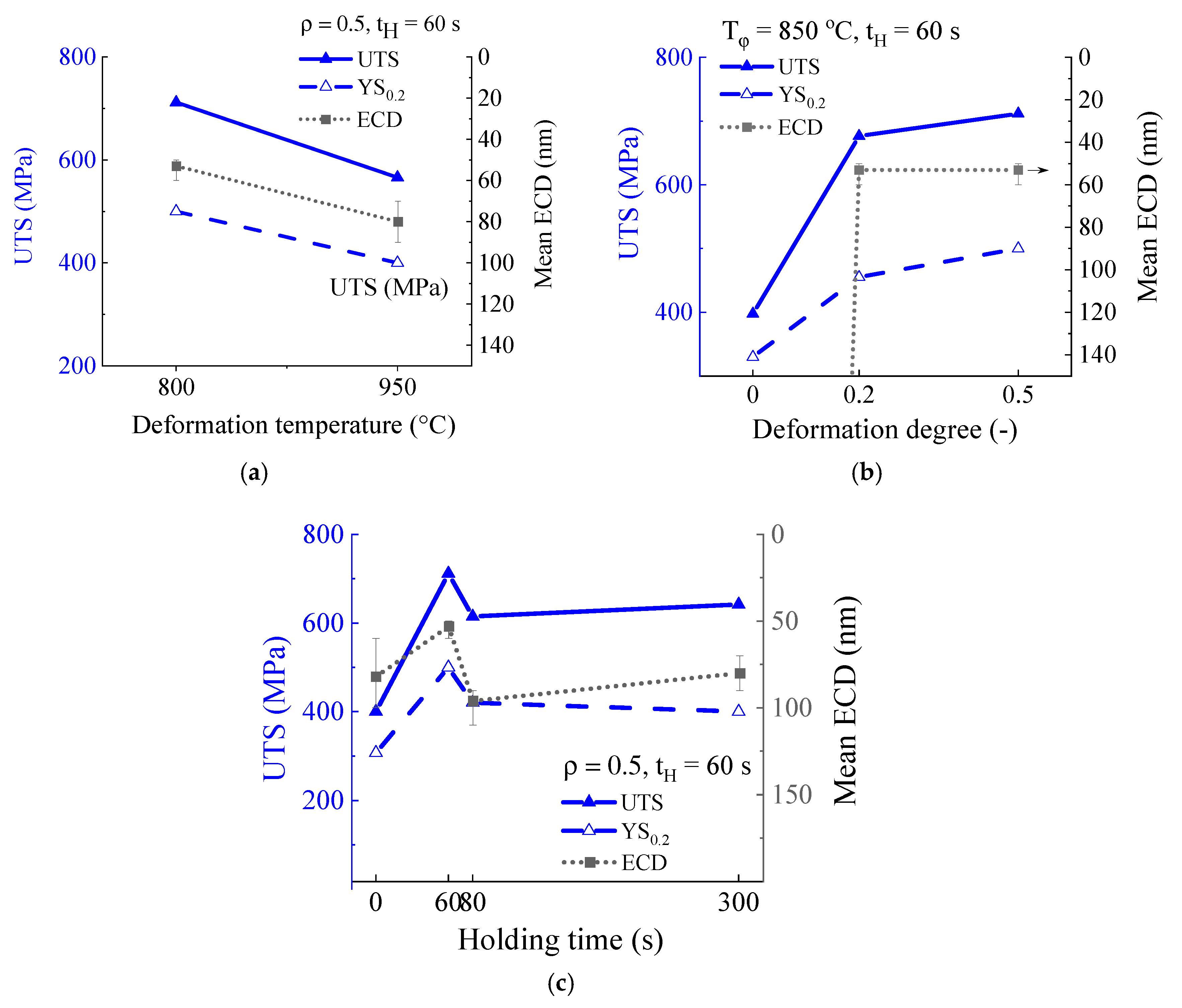
3.2.1. Temperature
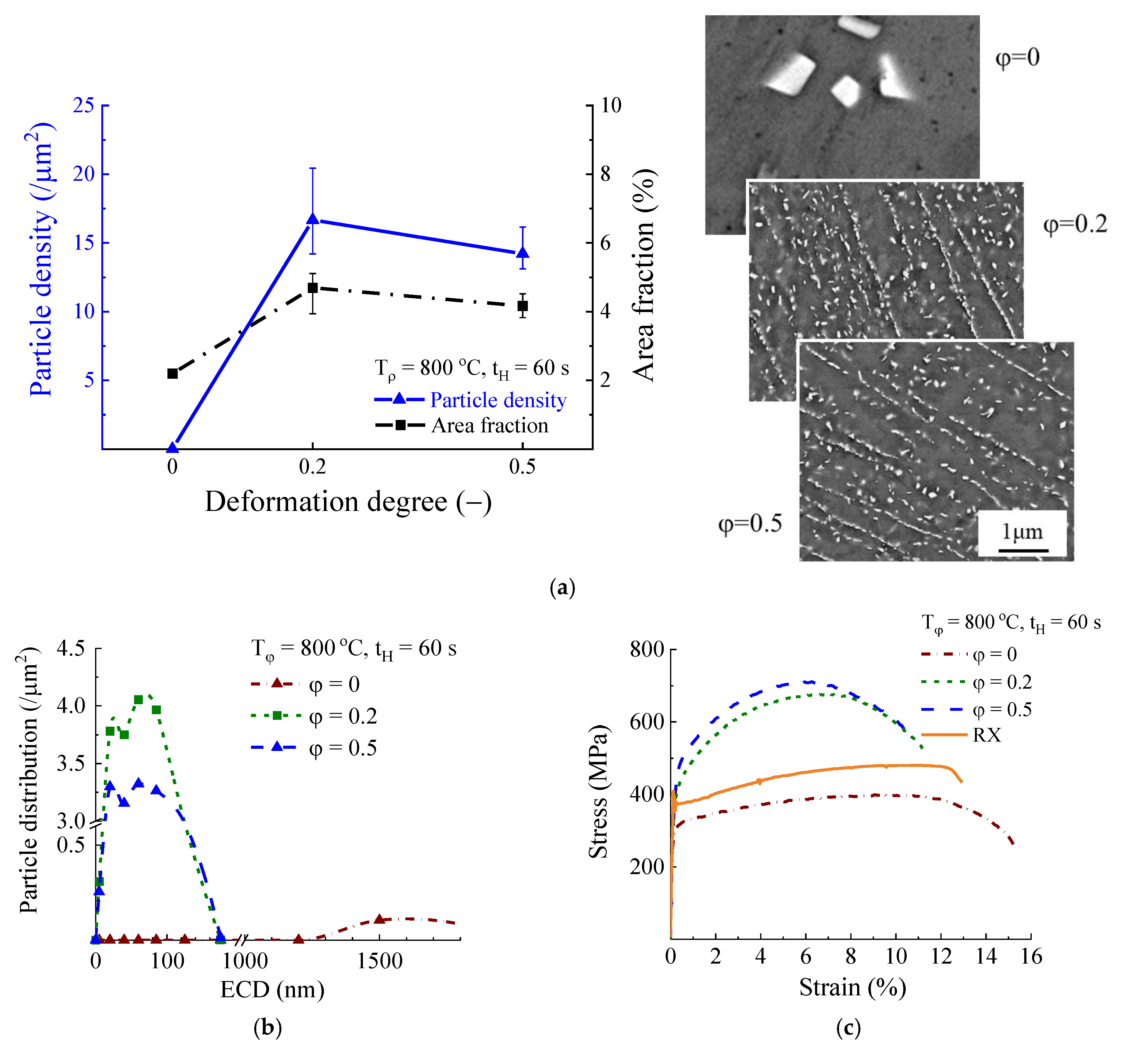
3.2.2. Deformation
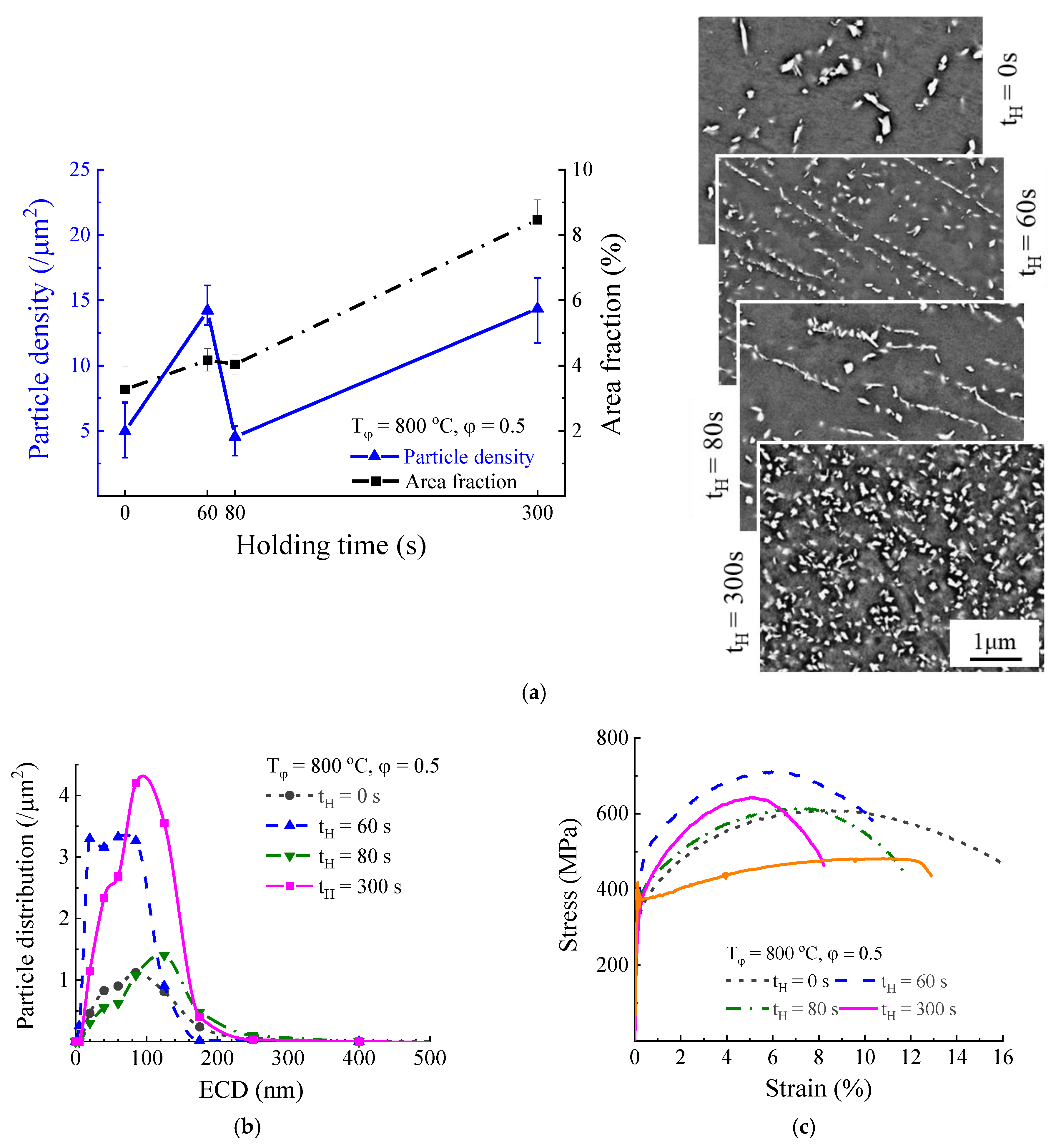
3.2.3. Holding Time
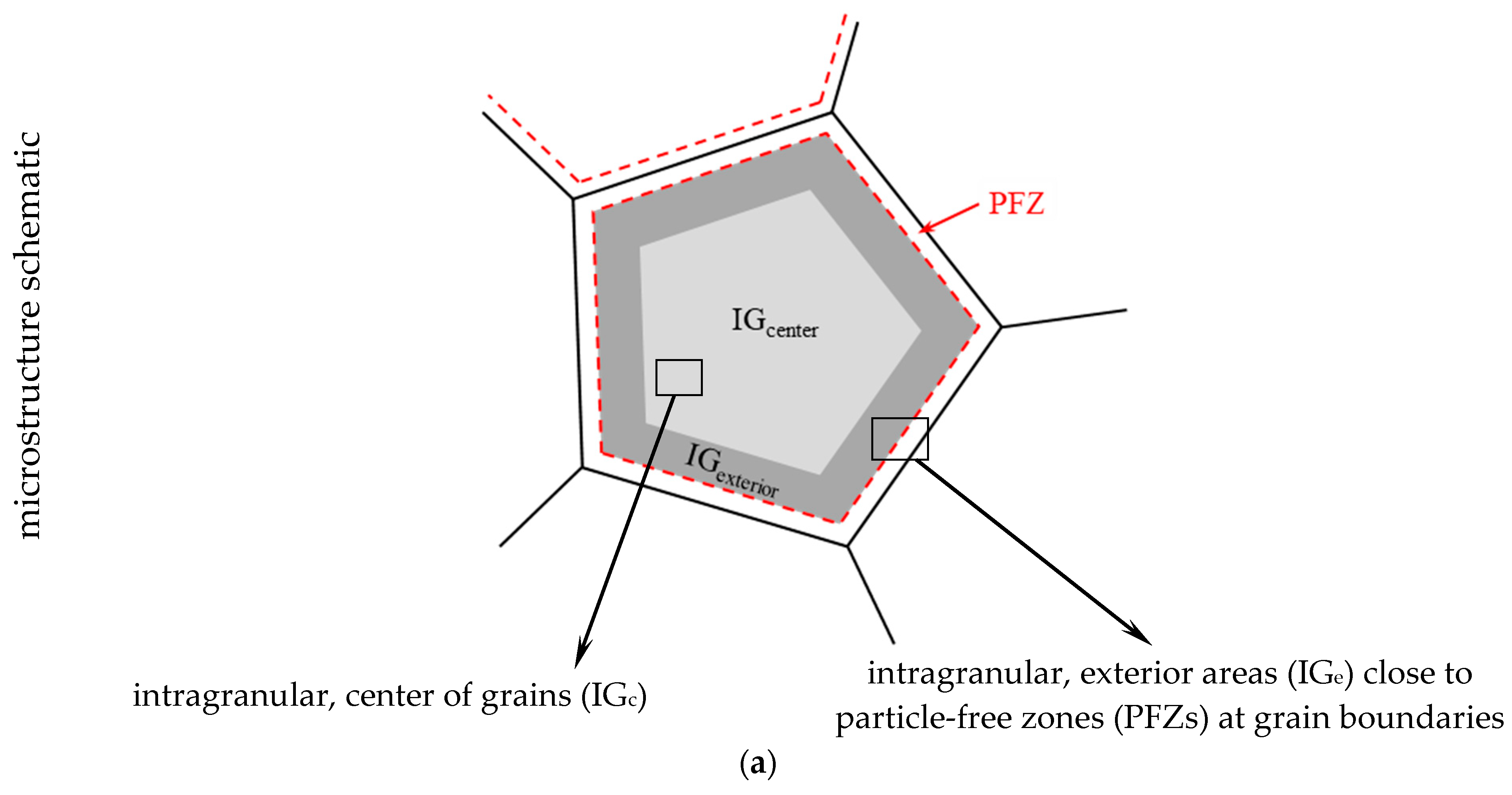
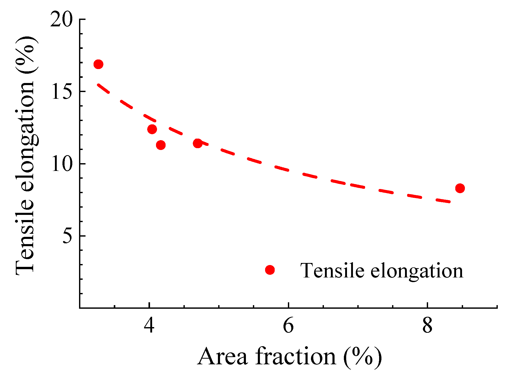
3.3. Comprehensive Correlation of Microstructure and Tensile Properties
4. Conclusions
Author Contributions
Funding
Acknowledgments
Conflicts of Interest
References
- Hsiao, Z.W.; Kuhn, B.; Chen, D.; Singheiser, L.; Kuo, J.C.; Lin, D.Y. Characterization of Laves phase in Crofer 22 H stainless steel. Micron 2015, 74, 59–64. [Google Scholar] [CrossRef]
- Quadakkers, W.J.; Zurek, J. Oxidation in Steam and Steam/Hydrogen Environments. In Shreir’s Corrosion; Cottis, B., Graham, M., Lindsay, R., Lyon, S., Richardson, T., Scantlebury, D., Stott, H., Eds.; Elsevier Science: Amsterdam, The Netherlands, 2010; Volume 1, pp. 407–456. [Google Scholar]
- Wright, I.; Dooley, R. A review of the oxidation behaviour of structural alloys in steam. Int. Mater. Rev. 2010, 55, 129–167. [Google Scholar] [CrossRef]
- Kuhn, B.; Talik, M. HiperFer—High performance ferritic steels. In Proceedings of the 10th Liége Conference on Materials for Advanced Power Engineering, Liége, Belgium, 14–17 September 2014; pp. 264–273. [Google Scholar]
- Kuhn, B.; Talik, M.; Zurek, J.; Beck, T.; Quadakkers, W.J.; Singheiser, L.; Hattendorf, H. Development of high chromium ferritic steels strengthened by intermetallic phases. In Proceedings of the 7th International Conference on Advances in Materials Technology for Fossil Power Plants, Waikoloa, HI, USA, 22–25 October 2013; pp. 1081–1092. [Google Scholar]
- Kuhn, B.; Fischer, T.; Yamamoto, Y.; Lopez Barrilao, J.; Fan, X. Mechanical properties and application potentials of high performance ferritic (HiperFer) steels. In Proceedings of the 4th International ECCC Creep & Fracture Conference, Duesseldorf, Germany, 10–14 September 2017. [Google Scholar]
- Kuhn, B.; Talík, M.; LI, C.; Zurek, J.; Quadakkers, W.J.; Beck, T.; Singheiser, L. Development of creep- and corrosion-resistance steels for future steam power plants. In Proceedings of the 1st International VDI Conference on Alloys in Power Plant Technology, Berlin, Germany, 12–13 June 2012. [Google Scholar]
- Kuhn, B.; Talik, M.; Fisher, L.; Fan, X.; Yamamoto, Y.; Lopez Barrilao, J. Science and technology of high performance ferritic (HiperFer) stainless steels. Metals 2020, 10, 463. [Google Scholar] [CrossRef]
- Lopez Barrilao, J.; Talík, M.; Kuhn, B.; Wessel, E. Properties and microstructure evolution of advanced high performance ferritic (HiperFer) steels. In Proceedings of the EPRI’s 9th International Conference on Advances in Materials Technology for Fossil Power Plants and the 2nd International 123HiMAT Conference on High-Temperature Materials, Nagasaki, Japan, 21–25 October 2019; pp. 246–252. [Google Scholar]
- Lopez Barrilao, J.; Kuhn, B.; Wessel, E.; Talík, M. Microstructure of intermetallic particle strengthened high-chromium fully ferritic steels. Mater. Sci. Technol. 2017, 33, 1056–1064. [Google Scholar] [CrossRef]
- Viswanathan, R.; Bakker, W. Materials for ultrasupercritical coal power plants—Boiler materials: Part 1. J. Mater. Eng. Perform. 2001, 10, 81–95. [Google Scholar] [CrossRef]
- Wright, I.; Tortorelli, P.; Schütze, M. Oxide growth and exfoliation on alloys exposed to steam. EPRI Rep. Nr. 2007, 1013666, 210. [Google Scholar]
- Maruyama, K.; Sawada, K.; Koike, J. Strengthening mechanisms of creep resistant tempered martensitic steel. ISIJ Int. 2001, 41, 641–653. [Google Scholar] [CrossRef]
- Abe, F. Precipitate design for creep strengthening of 9% Cr tempered martensitic steel for ultra-supercritical power plants. Sci. Technol. Adv. Mater. 2008, 9, 013002. [Google Scholar] [CrossRef]
- Abe, F. Bainitic and martensitic creep-resistant steels. Curr. Opin. Solid State Mater. Sci. 2004, 8, 305–311. [Google Scholar] [CrossRef]
- Yoshizawa, M.; Igarashi, M. Long-term creep deformation characteristics of advanced ferritic steels for USC power plants. Int. J. Press. Vessel. Pip. 2007, 84, 37–43. [Google Scholar] [CrossRef]
- Danielsen, H.K.; Hald, J.; Grumsen, F.B.; Somers, M.A.J. On the crystal structure of Z-phase Cr(V,Nb)N. Metall. Mater. Trans. A 2006, 37, 2633–2640. [Google Scholar] [CrossRef]
- Kuhn, B.; Talik, M.; Niewolak, L.; Zurek, J.; Hattendorf, H.; Ennis, P.J.; Quadakkers, W.J.; Beck, T.; Singheiser, L. Development of high chromium ferritic steels strengthened by intermetallic phases. Mater. Sci. Eng. A 2014, 594, 372–380. [Google Scholar] [CrossRef]
- Kuhn, B.; Talík, M.; Lopez Barrilao, J.; Singheiser, L.; Yamamoto, Y. Development status of high performance ferritic (HiperFer) steels. In Proceedings of the 8th International Conference on Advances in Materials Technology for Fossil Power Plants, Albufeira, Portugal, 11–14 October 2016. [Google Scholar]
- Talik, M.; Kuhn, B. High temperature mechanical properties of a 17wt%cr high performance ferritic (HiperFer) steel strengthened by intermetallic laves phase particles. In Proceedings of the 9th International Charles Parsons Turbine and Generator Conference, Loughborough, UK, 15–17 September 2015. [Google Scholar]
- Pandey, C.; Giri, A.; Mahapatra, M.M. Evolution of phases in P91 steel in various heat treatment conditions and their effect on microstructure stability and mechanical properties. MSEA 2016, 664, 58–74. [Google Scholar] [CrossRef]
- Barbadikar, D.R.; Deshmukh, G.S.; Maddi, L.; Laha, K.; Parameswaran, P.; Ballal, A.R.; Peshwe, D.R.; Paretkar, R.K.; Nandagopal, M.; Mathew, M.D. Effect of normalizing and tempering temperatures on microstructure and mechanical properties of P92 steel. Int. J. Press. Vessel. Pip. 2015, 132–133, 97–105. [Google Scholar] [CrossRef]
- Hsiao, Z.W.; Kuhn, B.; Yang, S.M.; Yang, L.C.; Huang, S.Y.; Singheiser, L.; Kuo, J.C. The Influence of deformation on the precipitation behavior of a ferritic stainless steel. In Proceedings of the 10th Liége Conference on Materials for Advanced Power Engineering, Liége, Belgium, 14–17 September 2014; pp. 349–358. [Google Scholar]
- Kuhn, B.; Talik, M.; Lopez Barrilao, J.; Singheiser, L. Microstructure stability of ferritic-martensitic, austenitic and fully ferritic steels under fluctuating loading conditions. In Proceedings of the 1st 123 HiMat Conference on Advanced High-Temperature Materials Technology for Sustainable and Reliable Power Engineering (123HiMAT-2015), Sapporo, Japan, 29 June–3 July 2015; pp. 94–97. [Google Scholar]
- Kuhn, B.; Lopez Barrilao, J.; Fischer, T. “Reactive” microstructure: The key to cost effective, fatigue resistant high temperature structural materials. In Proceedings of the EPRI’s 9th International Conference on Advances in Materials Technology for Fossil Power Plants and the 2nd International 123HiMAT Conference on High-Temperature Materials, Nagasaki, Japan, 21–25 October 2019; pp. 1–10. [Google Scholar]
- Pöpperlová, J.; Fan, X.; Kuhn, B.; Bleck, W.; Krupp, U. Impact of tungsten on thermomechanically induced precipitation of laves phase in high performance ferritic (HiperFer) stainless steels. Appl. Sci. 2020, 10, 4472. [Google Scholar] [CrossRef]
- Kuhn, B.; Lopez Barrilao, J.; Fischer, T.; Fan, X. Thermomechanical fatigue of a ferritic-martensitic 9 Cr and a ferritic, stainless 22 Cr steel. Appl. Sci. 2020, 10. in preparation. [Google Scholar]
- Lopez Barrilao, J.; Kuhn, B.; Wessel, E. Identification, size classification and evolution of Laves phase precipitates in high chromium, fully ferritic steels. Micron 2017, 101, 221–231. [Google Scholar] [CrossRef]
- Lopez Barrilao, J.; Kuhn, B. Microstructure Evolution of Laves Phase Strengthened Ferritic Steels for High Temperature Applications. Ph.D. Thesis, RWTH Aachen University, Aachen, Germany, 2016. [Google Scholar]
- Lopez Barrilao, J.; Kuhn, B.; Wessel, E. Microstructure and intermetallic particle evolution in fully ferritic steels. In Proceedings of the 8th International Conference on Advances in Materials Technology for Fossil Power Plants, Albufeira, Portugal, 11–14 October 2016; pp. 1029–1037. [Google Scholar]
- Lopez Barrilao, J.; Kuhn, B.; Wessel, E. Microstructure evolution and dislocation behaviour in high chromium, fully ferritic steels strengthened by intermetallic Laves phases. Micron 2018, 108, 11–18. [Google Scholar] [CrossRef]
- Romaniv, O.N.; Dyakiv, I.R. Effect of grain size on the ductility of steel in ductile fracture. Soviet materials science: A translation of Fiziko-khimicheskaya mekhanika materialov. Acad. Sci. Ukr. SSR 1969, 4, 75–76. [Google Scholar]
- Wagner, C. Theorie der alterung von niederschlägen durch umlösen (ostwald-reifung). Z. Elektrochem. Ber. Bunsenges. Phys. Chem. 1961, 65, 581–591. [Google Scholar]
- Ardell, A.J. On the coarsening of grain boundary precipitates. Acta Metall 1972, 20, 601–609. [Google Scholar] [CrossRef]
- Oono, N.; Nitta, H.; Iijima, Y. Diffusion of niobium in α-iron. Mater. Trans. 2003, 44, 2078–2083. [Google Scholar] [CrossRef]
- Takemoto, S.; Nitta, H.; Iijima, Y.; Yamazaki, Y. Diffusion of tungsten in α-iron. Philos. Mag. 2007, 87, 1619–1629. [Google Scholar] [CrossRef]
- Bhandarkar, M.D.; Bhat, M.S.; Parker, E.R.; Zackay, V.F. Creep and fracture of a Laves phase strengthened ferritic alloy. Metall. Trans. A 1976, 7, 753–760. [Google Scholar] [CrossRef]
- Fleischer, R.L. Mechanical properties of diverse high-temperature compounds–thermal variation of microhardness and crack formation. MRS Proc. 1988, 133, 305. [Google Scholar] [CrossRef]


| Batch ID: | Cr | W | Nb | Si | Mn | Fe | C | N |
|---|---|---|---|---|---|---|---|---|
| 17Cr5_1 | 17.43 | 3.85 | 0.9 | 0.25 | 0.25 | 77.33 | <0.01 | <0.001 |
| 17Cr5_2 | 17.30 | 3.97 | 0.93 | 0.27 | 0.23 | 77.40 | <0.01 | <0.001 |
| Tφ (°C) | φ (−) | tH (s) |
|---|---|---|
| 800, 950 | 0, 0.2, 0.5 | 0, 60, 80, 300 |
© 2020 by the authors. Licensee MDPI, Basel, Switzerland. This article is an open access article distributed under the terms and conditions of the Creative Commons Attribution (CC BY) license (http://creativecommons.org/licenses/by/4.0/).
Share and Cite
Fan, X.; Kuhn, B.; Pöpperlová, J.; Bleck, W.; Krupp, U. Thermomechanically Induced Precipitation in High-Performance Ferritic (HiperFer) Stainless Steels. Appl. Sci. 2020, 10, 5713. https://doi.org/10.3390/app10165713
Fan X, Kuhn B, Pöpperlová J, Bleck W, Krupp U. Thermomechanically Induced Precipitation in High-Performance Ferritic (HiperFer) Stainless Steels. Applied Sciences. 2020; 10(16):5713. https://doi.org/10.3390/app10165713
Chicago/Turabian StyleFan, Xiuru, Bernd Kuhn, Jana Pöpperlová, Wolfgang Bleck, and Ulrich Krupp. 2020. "Thermomechanically Induced Precipitation in High-Performance Ferritic (HiperFer) Stainless Steels" Applied Sciences 10, no. 16: 5713. https://doi.org/10.3390/app10165713
APA StyleFan, X., Kuhn, B., Pöpperlová, J., Bleck, W., & Krupp, U. (2020). Thermomechanically Induced Precipitation in High-Performance Ferritic (HiperFer) Stainless Steels. Applied Sciences, 10(16), 5713. https://doi.org/10.3390/app10165713