Featured Application
The present findings may find application in manufactured composite material for engineering purposes, load-bearing parts, and structural components.
Abstract
This paper presents an investigation on fracture behavior of carbon/epoxy composite laminates interleaved with electrospun nanofibers. Three different mats were manufactured and interleaved, using only polyvinylidene fluoride (PVDF), only polysulfone (PSF), and their combination. Mode-I and Mode-II fracture mechanics tests were conducted on virgin and nanomodified samples, and the results showed that PVDF and PSF nanofibers enhance the Mode-I critical energy release rate (GIC) by 66% and 51%, respectively, while using a combination of the two registered a 78% increment. The same phenomenon occurred under Mode-II loading. SEM micrographs were taken, to investigate the toughening mechanisms provided by the nanofibers.
1. Introduction
Carbon-fiber-reinforced polymer composites (CFRP) are applied widely in various industries, such as electronics, construction, and aeronautics. Among different resins, epoxy is the most frequently used because of its good mechanical properties, suitable fatigue resistance, and low shrinkage while curing. On the other side, its highly crosslinked structure leads to brittleness and thus to poor resistance to crack propagation [,]. Among the several methods that have been presented during the years to increase the fracture toughness of carbon/epoxy laminates [,,,], interleaving polymers [,,], in the form of particles, films, or nanofibrous mats [,,,,,,], has proved to be one of the most effective. In particular, nanofibrous mats have been found to be a suitable choice because of their high porosity (which lead to rapid penetration of epoxy) and the strengthening effects they are able to provide.
Literature reviews on nanofibers reinforcing composites are wide, and many polymers, such as polyvinylidene fluoride (PVDF) [,,,], polyvinyl butyral (PVB) [,,], polysulfone (PSF) [,,], Nylon [,,,,,,,], phenoxy [,], and carbon [,,] nanofibers, have been used to enhance composites’ mechanical properties. Saghafi et al. [] Showed that PVDF nanofibers can increase Mode-I fracture toughness by about 43%, while another study [] in this field had completely reverse outcomes. The considerations showed that the main reason was a non-suitable curing process and the high thickness of the nano-mat in the second study. As seen, some limited study was also conducted regarding the effect of PSF nanofibers on fracture behavior of nanomodified laminates. For instance, Li et al. [] used PSF nanofibers and PSF/carbon nanotube (CNT) hybrid nanofibers for increasing Mode-II energy release rate (GIIC) of carbon/epoxy laminate. According to results, PSF and the best combination of hybrid nanofibers (PSF + 10%wt of CNT) improved GIIC by about 11% and 50%, respectively.
The interesting matter in this regard is the toughening mechanisms that lead to improved properties when polymeric nanofibers are interleaved. (1) Fiber bridging: When nanofibers do not melt during curing cycle, they bridge the two layers they are interleaved between, thus hindering fracture propagation []. (2) Phase separation: Some nanofibers, such as polycaprolactone (PCL), due to the heat provided during the curing process, change shape to spherical particles and distribute in the matrix during curing, increasing fracture toughness due to crack deflections []. (3) Some other thermoplastic polymers, such as PVDF, melt and mixed with epoxy during curing, due to high porosity of the mat, and a plastic zone is produced in front of crack tip, capable of absorbing energy during loading [].
Interleaving nanofibers that can act different toughening mechanisms is an interesting topic, and this is what this paper means to present. Recently, Zheng et al. [] used a combination of nylon nanofibers and PCL film as interleave to increase the interlaminar fracture energy of carbon/epoxy laminates. The results demonstrated a synergistic effect; for instance, Mode-I fracture tests proved that fracture toughness for the laminates interleaved by nylon and PCL, separately, were enhanced by 30% and 50%, respectively, while a remarkable increase of 110% occurred for the laminates interleaved by nylon/PCL. In the present study, the effect of mixing two other mechanisms, i.e., phase separation and plastic zone, is considered. For this aim, electrospun PSF, PVDF, and PSF/PVDF nanofibers were produced separately and interleaved between carbon/epoxy laminate. Then, Mode-I and Mode-II fracture tests were conducted to investigate their effect. For deeper investigation, SEM pictures were also taken to find out toughening mechanism.
2. Materials and Methods
Electrospinning is a technique that uses a high-potential electrostatic field to produce fibers in scale of nano and micro. The machine used to produce the nanofibers is made of (1) a high-voltage source with positive or negative polarity, (2) a syringe pump with Teflon tubes to carry the solution to needles, and (3) a conductive collector, in the form of a rotating drum. The electrospinning process is schematically shown in Figure 1. In the following subsections, further information regarding the applied materials and electrospinning parameters, such as voltage and injection rate, are presented.
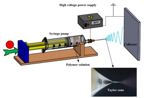
Figure 1.
Schematic picture of producing nanofibers by using the electrospinning process.
2.1. Polymers
Polysulfone (Udel® 3500) and polyvinylidene fluoride (Solef® 6008) polymers in the form of pellets and powder, respectively, were supplied by Solvay Specialty Polymers. Their properties are presented in Table 1. Acetone and N, N-Dimethylacetamide (DMAc) and Dimethyl sulfoxide purchased from Sigma-Aldrich Co. were used as the solvent for preparing polymeric solutions.

Table 1.
Polysulfone (PSF) and polyvinylidene fluoride (PVDF) properties (source: datasheet provided by Solvay website).
2.2. Electrospinning
The “lab unit” electrospinning machine by Spinbow company (Bologna, Italy) was used for producing 30 m thick nanofibrous mats. The polymeric solutions of PSF and PVDF were made as follows: (1) PSF solution was prepared by dissolving 23 g of polymer in 90 mL of DMAc and 10 mL of acetone. (2) The second solution was produced by dissolving 15% (w/v) PVDF powder in a 30:70 (v/v) of Dimethyl sulfoxide (DMSO) and Acetone. The solutions were poured into two separate syringes and then transferred to the electrospinning machine. The electrospinning parameters are presented in Table 2.
Table 2.
Electrospinning parameters.
A continuous electrospinning process was conducted for producing pure PSF and PVDF nanofibrous mat, but as the electrospinning machine was not equipped with two separate high-voltage sources and syringe pumps, and due to different feed rates for the two polymers, the process was discontinuous for the mixed (PVDF/PSF) nanofibrous mat: PSF and PVDF nanofibers were electrospun for 1 and 2 min, respectively, until the desired thickness was obtained. SEM pictures of PVDF and PSF nanofibers are shown in Figure 2.
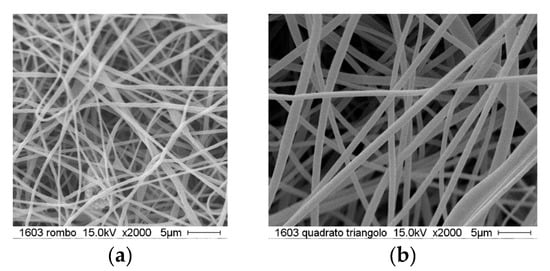
Figure 2.
Produced nanofibers: (a) PVDF and (b) PSF.
2.3. DCB and ENF Specimens
Double cantilever beam (DCB) and end-notched flexure (ENF) specimens were manufactured and tested under Mode-I and Mode-II fracture loadings, according to ASTM D5528 [] and guidelines provided by [], respectively. The samples were manufactured by stacking 14 layers of prepreg woven carbon/epoxy laminates (twill 2/2 240 gsm supplied by Impregnatex Composite Srl) on each other, and the nanofibrous mat and a 15 m thick Teflon layer interleaved between mid-layers. After the lay-up, samples were sealed completely, using a vacuum bag, and transferred to an autoclave to cure: from room temperature to 170 °C (at 1 °C/min), then 1 h at 170 °C, from 170 °C to 190 °C (at 1 °C/min), then 20 min at 190 °C, and finally the oven was shut off and kept closed until complete cooling. Samples were 20 mm wide and 4.2 mm thick, the initial crack length was 59 mm for DCB samples and 40 mm for the ENF ones, and total length was 140 mm (DCB) and 150 mm (ENF). Three samples were produced for each configuration.
2.4. Mode-I Interlaminar Fracture Test
In order to load the samples, aluminum blocks were glued to each side of the samples, as shown in Figure 3. In order to observe the delamination progress by a digital image correlation (DIC) system and measure the crack length (more details in Reference []), one side of each sample was coated with a white paint first, and then with a black paint, to obtain a random pattern. The tests were performed in a universal testing machine (Instron 8033), at a constant crosshead speed of 1.5 mm/min. The following expression was used to calculated GIC []:
where F is the applied load, δ is the displacement of loading point, B is the width of specimen, and a is the crack length.
GIC = 3Fδ/2Ba,
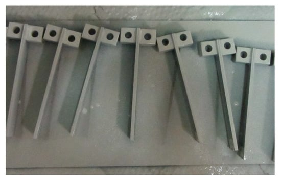
Figure 3.
Double cantilever beam (DCB) samples after white painting.
2.5. Mode-II Interlaminar Fracture Test
ENF samples were used to conduct Mode-II fracture tests in a three-point bending load configuration, as shown in Figure 4, at a crosshead speed of 1 mm/min, on the same machined used for Mode-I tests. Span length was 100 mm; therefore, the distance between the crack tip and the loading point was 35 mm. For calculating GIIC, the following formula was applied []:
where a, B, L, F, and δ are the crack length, specimen width, span length, force, and displacement, respectively.
GIIC = (4.5a^2 Fδ)/(B(0.25L^3+3a^3)),
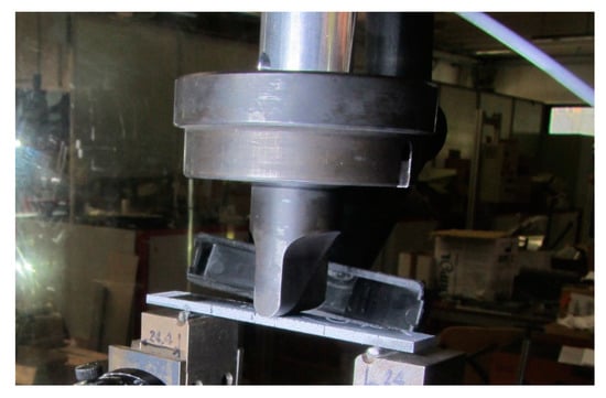
Figure 4.
End-notched flexure (ENF) sample under Mode-II test.
3. Results
3.1. Test Results
Figure 5 shows the force-displacement curves for the reference and modified samples under DCB loadings, and Table 3 presents the results. As seen, the PSF and PVDF did not affect the slope of the linear loading phase before crack propagation. An interesting phenomenon is observed while the crack propagates. In the reference laminate, a high number of short rises and falls of the force is registered, unlike the modified laminates, especially the PSF- and PVDF/PSF-modified ones, where a lower number of variations is registered (see the orange ovals in the figures). In nanomodified samples, the force rises after a drop up to about 6N, which is 15% of the maximum load.
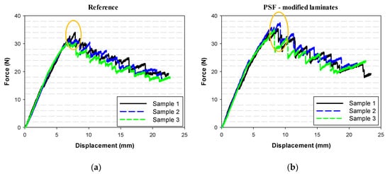

Figure 5.
Mode-I fracture test (DCB) outcome for reference (a) PSF-only, (b) PVDF-only, (c) PVDF/PSF (d) nanomodified samples.
Table 3.
DCB test results.
The maximum load (Fmax) was 32.7 N for the reference laminate, and it increased 11% and 21% by applying PSF and PVDF nanofibers, respectively; GIC for the non-modified sample is 255 N/m, whereas, for the PVDF, PSF, and PVDF/PSF samples, it is 423, 384 and 454 N/m, respectively. By comparison with the reference, the energy-release rate of PSF- and PVDF-modified laminates was enhanced by 51% and 66%, respectively, and a higher enhancement of 78% was obtained by using the mixed nanofibrous mat.
ENF test curves are shown in Figure 6, and the results are presented in Table 4. The behavior of the two types of samples differs at the fracture initiation stage. The crack started to propagate 60–80 N below the Fmax in both control the PSF-modified samples. In this critical point, the slope of force-displacement curve decreases, flagging a crack propagation. In the PVDF-modified laminate, the crack initiation was followed by a force drop, about 40–60 N, in various samples. Then, the force increased again up to the maximum load. The force-displacement curve of the laminates interleaved by PVDF/PSF has some similarities with both of the two other modified samples. In the stage of crack initiation, a very small force drop was observed, and then the load increased about 10–20 N, up to the Fmax with a lower slope.
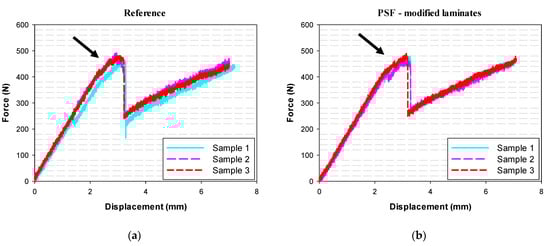
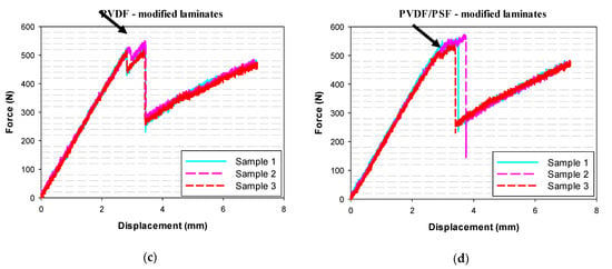
Figure 6.
Mode-II fracture test (ENF) outcomes for reference (a), PSF-only (b), PVDF-only (c) and PVDF/PSF (d) nanomodified samples.
Table 4.
ENF test results.
According to Table 4, reference and PSF-modified laminates have similar values of maximum load and GIIC. Therefore, the PSF nanofibers do not show significant effect on toughening the virgin laminate, while its influence in Mode-I loading was positive. On the other hand, PVDF and PVDF/PSF nanofibers increased the GIIC of the laminate by 57% and 75%, respectively. It is interesting to note that, although the influence of PSF nanofibers on GIIC was negligible, its mixture with PVDF had a synergistic effect. A similar phenomenon was observed by Zheng et al. []. They used PCL film, nylon nanofibers, and their mixture for toughening carbon/epoxy laminates: According to their results, presented in Table 5, each interlayer individually increased GIIC by 20%, while their mixture almost doubled it.
Table 5.
The influence of PCL film, Nylon 66 nanofibrous mat, and their mixture on GIIC [].
3.2. Toughening Mechanisms
Figure 5 shows the force-displacement curves for the reference and modified samples under DCB loadings, and Table 3 presents the results. As seen, the PSF and PVDF did not affect the slope of the linear loading phase before crack propagation. An interesting phenomenon is observed while the crack propagates. In the reference laminate, a high number of short rises and falls of the force is registered, unlike the modified laminates, especially the PSF- and PVDF/PSF-modified ones, where a lower number of variations is registered (see the orange ovals in the figures). In nanomodified samples, the force rises after a drop up to about 6N, which is 15% of the maximum load.
Figure 7 presents the SEM micrographs of the fractured surfaces of the reference and nanomodified laminates. As seen in Figure 7a, the surface of fractured neat epoxy is smooth, a sign of a brittle type of fracture; instead, for the other samples, images show a different situation and various toughening mechanisms.
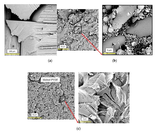
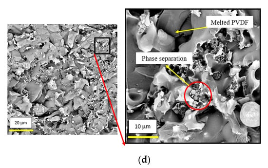
Figure 7.
Morphology of fractured surface in (a) reference, (b) PSF-, (c) PVDF-, and (d) PVDF/PSF-modified laminates.
Due to high porosity and specific surface area, PSF mats were easily impregnated by the epoxy. On the other hand, owing to PSF’s high viscosity and fast curing of resin, the diffusion of PSF in the epoxy was more difficult. Subsequently, the nanofibers were dissolved in the resin. By continuing the curing process, PSF started a phase separation from the epoxy and changed to spherical particles (see Figure 7b). When the crack tip reached these particles, it was restrained and deflected from its path, requiring higher energy to propagate.
4. Discussion
As the curing temperature of composite laminates was higher than the melting point of PVDF (170 °C), the nanofibers melted. As mentioned before, the porous nature of nanofibrous mats caused the epoxy to permeate completely into the PVDF mats before hardening, and, therefore, the PVDF blended with the epoxy by the end of curing process (see Figure 7c). Since PVDF is a thermoplastic polymer, its toughness is higher than thermosets like epoxy; therefore, more energy is required for crack propagation in the blend of PVDF/epoxy. Furthermore, a plastic zone area was detected in front of the crack tip, which could again absorb more energy in comparison with the crack propagated in pure epoxy. Figure 7d illustrates the sample modified by PVDF/PSF nanofibrous mat, showing both the toughening mechanism of each individual nanofiber, i.e., melted PVDF and PSF spherical particles, which both hindered fracture propagation.
5. Conclusions
In this study, two thermoplastic polymers, i.e., PVDF and PSF, were applied individually and at the same time, in form on nanofibers into CFRP, to study their influence on GIC and GIIC. The investigation produced the following results:
- Interleaving reference laminates with nanofibers made of both polymers lead to increased Mode-I and Mode-II energy-release rates;
- PVDF nanofibers offer better results than PSF nanofibers: the first improved GIC and GIIC by 57% and 66% against 9% and 51%, respectively, of the latter;
- Mixed PVDF/PSF nanofibrous mat had a synergistic influence, increasing Mode-I and Mode-II energy-release rate by 75% and 78%, respectively. These results are similar to the results presented in Reference [], in which PCL film/nylon nanofibers were applied.
- SEM micrographs showed that PSF started to engage in phase separation from the epoxy and changed to spherical particles during curing process. Hence, when the crack tip reached these particles, it deflected from its main path and absorbed energy.
- When PVDF nanofibers are interleaved, they mix with epoxy and melt during cure, creating a plastic zone in front of the crack tip, requiring higher energy for it to propagate. The melting is a critical factor; otherwise, the PVDF cannot affectively toughen the laminates.
Author Contributions
Conceptualization, H.S. and R.P.; methodology, H.S., A.Z., and H.H.; investigation, H.S. and R.P.; data curation, T.M.B.; writing—original draft preparation, H.S.; writing—review and editing, R.P.; visualization, T.M.B.; supervision, G.M. All authors have read and agreed to the published version of the manuscript.
Funding
This research received no external funding.
Conflicts of Interest
The authors declare no conflict of interest.
References
- Wagih, A.; Sebaey, T.A.; Yudhanto, A.; Lubineau, G. Post-impact flexural behavior of carbon-aramid/epoxy hybrid composites. Compos. Struct. 2020, 239, 112022. [Google Scholar] [CrossRef]
- Al-Hajaj, Z.; Sy, B.L.; Bougherara, H.; Zdero, R. Impact properties of a new hybrid composite material made from woven carbon fibres plus flax fibres in an epoxy matrix. Compos. Struct. 2019, 208, 346–356. [Google Scholar] [CrossRef]
- Esmaeeli, M.; Nami, M.R.; Kazemianfar, B. Geometric analysis and constrained optimization of woven z-pinned composites for maximization of elastic properties. Compos. Struct. 2019, 210, 553–566. [Google Scholar] [CrossRef]
- Moallemzadeh, A.R.; Sabet, S.A.R.; Abedini, H.; Saghafi, H. Investigation into high velocity impact response of pre-loaded hybrid nanocomposite structure. Thin-Walled Struct. 2019, 142, 405–413. [Google Scholar] [CrossRef]
- Zhang, D.; Zheng, X.; Wang, Z.; Wu, T.; Sohail, A. Effects of braiding architectures on damage resistance and damage tolerance behaviors of 3D braided composites. Compos. Struct. 2020, 232, 111565. [Google Scholar] [CrossRef]
- Wang, J.; Ma, C.; Chen, G.; Dai, P. Interlaminar fracture toughness and conductivity of carbon fiber/epoxy resin composite laminate modified by carbon black-loaded polypropylene non-woven fabric interleaves. Compos. Struct. 2020, 234, 111649. [Google Scholar] [CrossRef]
- Saghafi, H.; Fotouhi, M.; Minak, G. Improvement of the Impact Properties of Composite Laminates by Means of Nano-Modification of the Matrix—A Review. Appl. Sci. 2018, 8, 2406. [Google Scholar] [CrossRef]
- Palazzetti, R.; Zucchelli, A. Electrospun nanofibers as reinforcement for composite laminates materials—A review. Compos. Struct. 2017, 182, 711–727. [Google Scholar] [CrossRef]
- Saghafi, H.; Brugo, T.; Minak, G.; Zucchelli, A. Improvement the impact damage resistance of composite materials by interleaving Polycaprolactone nanofibers. Eng. Solid Mech. 2015, 3, 21–26. [Google Scholar] [CrossRef]
- Li, P.; Liu, D.; Zhu, B.; Li, B.; Jia, X.; Wang, L.; Li, G.; Yang, X. Synchronous effects of multiscale reinforced and toughened CFRP composites by MWNTs-EP/PSF hybrid nanofibers with preferred orientation. Compos. Part. A Appl. Sci. Manuf. 2015, 68, 72–80. [Google Scholar] [CrossRef]
- Li, G.; Li, P.; Yu, Y.; Jia, X.; Zhang, S.; Yang, X.; Ryu, S.-K. Novel carbon fiber/epoxy composite toughened by electrospun polysulfone nanofibers. Mater. Lett. 2008, 62, 511–514. [Google Scholar] [CrossRef]
- Xuefeng, A.N.; Shuangying, J.I.; Bangming, T.; Zilong, Z.; Xiao-Su, Y. Toughness improvement of carbon laminates by periodic interleaving thin thermoplastic films. J. Mater. Sci. Lett. 2002, 21, 1763–1785. [Google Scholar] [CrossRef]
- Guo, Z.; Li, Z.; Liu, J.; Chen, M.; Zu, Q.; Zhang, Y.; Chen, J. Ex-Situ method for toughening glass/epoxy composites by interlaminar films made of polyetherketone cardo and calcium sulfate whisker. J. Reinf. Plast. Compos. 2014, 33, 1966–1975. [Google Scholar] [CrossRef]
- Adak, N.C.; Chhetri, S.; Kuila, T.; Murmu, N.C.; Samanta, P.; Lee, J.H. Effects of hydrazine reduced graphene oxide on the inter-laminar fracture toughness of woven carbon fiber/epoxy composite. Compos. Part. B Eng. 2018, 149, 22–30. [Google Scholar] [CrossRef]
- Daelemans, L.; van der Heijden, S.; de Baere, I.; Rahier, H.; van Paepegem, W.; de Clerck, K. Improved fatigue delamination behaviour of composite laminates with electrospun thermoplastic nanofibrous interleaves using the Central Cut-Ply method. Compos. Part. A Appl. Sci. Manuf. 2017, 94, 10–20. [Google Scholar] [CrossRef]
- Sarasini, F.; Tirillò, J.; Bavasso, I.; Bracciale, M.P.; Sbardella, F.; Lampani, L.; Cicala, G. Effect of electrospun nanofibres and MWCNTs on the low velocity impact response of carbon fibre laminates. Compos. Struct. 2020, 234, 111776. [Google Scholar] [CrossRef]
- Saghafi, H.; Moallemzadeh, A.R.; Zucchelli, A.; Brugo, T.M.; Minak, G. Shear mode of fracture in composite laminates toughened by polyvinylidene fluoride nanofibers. Compos. Struct. 2019, 227, 111327. [Google Scholar] [CrossRef]
- Magniez, K.; de Lavigne, C.; Fox, B.L. The effects of molecular weight and polymorphism on the fracture and thermo-mechanical properties of a carbon-fibre composite modified by electrospun poly (vinylidene fluoride) membranes. Polymer 2010, 51, 2585–2596. [Google Scholar] [CrossRef]
- Zhang, J.; Yang, T.; Lin, T.; Wang, C.H. Phase morphology of nanofibre interlayers: Critical factor for toughening carbon/epoxy composites. Compos. Sci. Technol. 2012, 72, 256–262. [Google Scholar] [CrossRef]
- Saghafi, H.; Brugo, T.; Minak, G.; Zucchelli, A. The effect of PVDF nanofibers on mode-I fracture toughness of composite materials. Compos. Part. B Eng. 2015, 72, 213–216. [Google Scholar] [CrossRef]
- Kheirkhah Barzoki, P.; Rezadoust, A.M.; Latifi, M.; Saghafi, H. The experimental and numerical study on the effect of PVB nanofiber mat thickness on interlaminar fracture toughness of glass/phenolic composites. Eng. Fract. Mech. 2018, 194, 145–153. [Google Scholar] [CrossRef]
- Barzoki, P.K.; Rezadoust, A.M.; Latifi, M.; Saghafi, H.; Minak, G. Effect of nanofiber diameter and arrangement on fracture toughness of out of autoclave glass/phenolic composites—Experimental and numerical study. Thin-Walled Struct. 2019, 143, 106251. [Google Scholar] [CrossRef]
- Taheri, H.; Oliaei, M.; Ipakchi, H.; Saghafi, H. Toughening phenolic composite laminates by interleaving hybrid pyrolytic carbon/polyvinyl butyral nanomat. Compos. Part. B Eng. 2020, 191, 107981. [Google Scholar] [CrossRef]
- Zheng, N.; Huang, Y.; Liu, H.Y.; Gao, J.; Mai, Y.W. Improvement of interlaminar fracture toughness in carbon fiber/epoxy composites with carbon nanotubes/polysulfone interleaves. Compos. Sci. Technol. 2017, 140, 8–15. [Google Scholar] [CrossRef]
- Saghafi, H.; Minak, G.; Zucchelli, A.; Brugo, T.M.; Heidary, H. Comparing various toughening mechanisms occurred in nanomodified laminates under impact loading. Compos. Part. B Eng. 2019, 174, 106964. [Google Scholar] [CrossRef]
- Saghafi, H.; Ghaffarian, S.R.; Yademellat, H.; Heidary, H. Finding the best sequence in flexible and stiff composite laminates interleaved by nanofibers. J. Compos. Mater. 2019, 53. [Google Scholar] [CrossRef]
- Ahmadloo, E.; Gharehaghaji, A.; Latifi, M.; Saghafi, H.; Mohammadi, N. Effect of PA66 nanofiber yarn on tensile fracture toughness of reinforced epoxy nanocomposite. Proc. Inst. Mech. Eng. Part. C J. Mech. Eng. Sci. 2018, 233. [Google Scholar] [CrossRef]
- Gholizadeh, A.; Najafabadi, M.A.; Saghafi, H.; Mohammadi, R. Considering damage during fracture tests on nanomodified laminates using the acoustic emission method. Eur. J. Mech. A/Solids 2018, 72, 452–463. [Google Scholar] [CrossRef]
- Gholizadeh, A.; Najafabadi, M.A.; Saghafi, H.; Mohammadi, R. Considering damages to open-holed composite laminates modified by nanofibers under the three-point bending test. Polym. Test. 2018, 70, 363–377. [Google Scholar] [CrossRef]
- Yademellat, H.; Nikbakht, A.; Saghafi, H.; Sadighi, M. Experimental and numerical investigation of low velocity impact on electrospun nanofiber modified composite laminates. Compos. Struct. 2018, 200, 507–514. [Google Scholar] [CrossRef]
- Mohammadi, R.; Najafabadi, M.A.; Saghafi, H.; Zarouchas, D. Fracture and fatigue behavior of carbon/epoxy laminates modified by nanofibers. Compos. Part. A Appl. Sci. Manuf. 2020, 137, 106015. [Google Scholar] [CrossRef]
- Mohammadi, R.; Najafabadi, M.A.; Saghafi, H.; Zarouchas, D. Mode-II fatigue response of AS4/8552 carbon /epoxy composite laminates interleaved by electrospun nanofibers. Thin-Walled Struct. 2020, 154, 106811. [Google Scholar] [CrossRef]
- Zhang, H.; Bharti, A.; Li, Z.; Du, S.; Bilotti, E.; Peijs, T. Localized toughening of carbon/epoxy laminates using dissolvable thermoplastic interleaves and electrospun fibres. Compos. Part. A Appl. Sci. Manuf. 2015, 79, 116–126. [Google Scholar] [CrossRef]
- Magniez, K.; Chaffraix, T.; Fox, B. Toughening of a carbon-fibre composite using electrospun poly(hydroxyether of bisphenol A) nanofibrous membranes through inverse phase separation and inter-domain etherification. Materials 2011, 4, 1967–1984. [Google Scholar] [CrossRef]
- Wang, Y.; Wang, Y.; Wan, B.; Han, B.; Cai, G.; Chang, R. Strain and damage self-sensing of basalt fiber reinforced polymer laminates fabricated with carbon nanofibers/epoxy composites under tension. Compos. Part. A Appl. Sci. Manuf. 2018, 113, 40–52. [Google Scholar] [CrossRef]
- Ravindran, A.R.; Ladani, R.B.; Wang, C.H.; Mouritz, A.P. Synergistic mode II delamination toughening of composites using multi-scale carbon-based reinforcements. Compos. Part. A Appl. Sci. Manuf. 2019, 117, 103–115. [Google Scholar] [CrossRef]
- Hsiao, K.T.; Scruggs, A.M.; Brewer, J.S.; Hickman, G.J.S.; McDonald, E.E.; Henderson, K. Effect of carbon nanofiber z-threads on mode-I delamination toughness of carbon fiber reinforced plastic laminates. Compos. Part. A Appl. Sci. Manuf. 2016, 91, 324–335. [Google Scholar] [CrossRef]
- Palazzetti, R.; Zucchelli, A.; Gualandi, C.; Focarete, M.L.; Donati, L.; Minak, G.; Ramakrishna, S. Influence of electrospun Nylon 6,6 nanofibrous mats on the interlaminar properties of Gr–epoxy composite laminates. Compos. Struct. 2012, 94, 571–579. [Google Scholar] [CrossRef]
- Zheng, N.; Liu, H.Y.; Gao, J.; Mai, Y.W. Synergetic improvement of interlaminar fracture energy in carbon fiber/epoxy composites with nylon nanofiber/polycaprolactone blend interleaves. Compos. Part. B Eng. 2019, 171, 320–328. [Google Scholar] [CrossRef]
- ASTM D5528. Standard Test Method for Mode I Interlaminar Fracture Toughness of Unidirectional Fiber-Reinforced Polymer Matrix Composites; Annual Book of ASTM Standards; ASTM: West Conshohocken, PA, USA, 2009. [Google Scholar]
- European Structural Integrity Society. Protocol No 2 for Interlaminar Fracture Toughness Testing of Composites: Mode II, Bordeaux; European Structural Integrity Society: Delft, The Netherlands, 1993. [Google Scholar]
- Saghafi, H.; Ghaffarian, S.R.; Brugo, T.M.; Minak, G.; Zucchelli, A.; Saghafi, H.A. The effect of nanofibrous membrane thickness on fracture behaviour of modified composite laminates—A numerical and experimental study. Compos. Part. B Eng. 2016, 101, 116–123. [Google Scholar] [CrossRef]
© 2020 by the authors. Licensee MDPI, Basel, Switzerland. This article is an open access article distributed under the terms and conditions of the Creative Commons Attribution (CC BY) license (http://creativecommons.org/licenses/by/4.0/).