1. Introduction
Cables are widely used in construction, cable cars, traction, and other fields due to their extremely high tensile strength, long-distance capabilities, and low cost. This article will conduct research that is based on the cable-stayed bridge, which is the most representative and technically demanding application of cables, and illustrate a novel vibration energy absorbing mechanism that effectively responds to common vibration that is caused by environmental impacts with the automatic switching modes of the non-stiffness vibration isolators with the hydraulic viscous dampers.
In recent years, the cable-stayed bridge design has gained popularity as the design of choice for the construction of long-span bridges. This can be attributed to its simple and beautiful design, and its ability to span longer distances at relatively low construction costs [
1]. From 2016 to 2019, a total of 20 cable stayed bridges with spans over 500 m were built around the world. Currently, the longest span cable-stayed bridge in the world is the Russky Bridge built over the Eastern Bosphorous in Russia, which has a span of 1104 m. Although the span of this bridge is quite short when compared to suspension bridges, the trend in construction seems to be moving towards an increasing number and spans of cable-stayed bridges. The cable-stayed bridge is mainly composed of bridge pylons, cables, and decks. The cables connect the decks to the pylons directly, so that the pylons carry the entire load. Like all structures, cable-stayed bridges are also subjected to vibration resulting from such exogenous factors, such as wind, rain, temperature change, and the movement of pedestrians and vehicles. These vibrations are transmitted to pylons and decks by the cables [
2]. If the excitation frequency is close to a natural frequency of the bridge system, resonance will occur. Resonance is regarded as one of the main causes of bridge damage leading to fatigue and shortened life [
3,
4,
5,
6,
7]. Therefore, a great amount of effort has been undertaken to develop methods for avoiding/mitigating the effects of vibration on cable-stayed bridge structures. Increasing the damping between the cable and the bridge deck is one of the key methods used to improve the robustness of cable-stayed bridges by preventing the occurrence of resonance.
Various types of vibration control systems are used in a wide variety of fields, such as automotive, aerospace, and structural engineering. According to their working mechanisms, vibration control systems for cable-stayed bridges can be divided into: (1) high-damping rubber (HDR) dampers, (2) viscous dampers, (3) magneto-rheological (MR) dampers, and (4) friction dampers.
Rubber dampers are the oldest type of damping systems used in cable-stayed bridges. These dampers dissipate vibration energy via hysteretic losses. Nakamura et al. [
8] proposed an external high-damping rubber (HDR) damper for cable-stayed bridges and experimentally evaluated its performance against dynamic vibration. Cu et al. [
9,
10] formulated a complex eigen value problem in order to address the different damping effects of a single HDR damper and two attached HDR dampers under different installation conditions and material loss factors. Their work provides a strong theoretical basis for the design of HDR dampers. The damping performance of the HDR damper is highly dependent on the damping characteristics of its material, e.g., rubber. However, rubber materials have a limited energy consumption performance and they are easily affected by environmental factors, such as temperature.
The viscous damper category is mainly comprised of hydraulic cylinder type dampers that dissipate the vibration energy through the friction between the hydraulic fluid and their orifice(s). The maximum damping ratio of a viscous damper has a relationship with the relative distance between the support and the damper. This was proposed by Pacheco et al. [
11], who also derived an optimal damping constant for viscous dampers with low modes of vibration. A later study by Krenk [
12] optimized the modal damping values of the lowest five modes of vibration. Sawka [
13] experimentally studied the total pressures of viscous dampers as a function of time after excitation by a mass impact. This work showed that viscous dampers show better damping performance against large dynamic vibrations, but they are not sensitive enough to small amplitude vibrations. Tomski and Kukla et al. [
14] confirmed these results through numerical simulations. Viscous dampers are susceptible to reduction in load capacity due to load misalignment. In order to explore this further, Gamez-Montero et al. [
15] performed a buckling analysis on hydraulic cylinders, while Niu et al. [
16] proposed an oil damper with variable stiffness (ODVS). In their designs, the orifice size of the variable overflow valve can be changed to achieve a variable damping ratio according to different hydraulic loads. Viscous dampers are also susceptible to leakage due to thermal deformation and aging of the seal ring due to frequent reciprocating movements that are mostly associated with low amplitude vibrations. To overcome the problem of leakage, Zhan et al. [
17] proposed the design of a third-generation hydraulic cylinder with a special lip shape at the piston periphery that varies the clearance between the piston and the cylinder according to the change in hydraulic pressure. A common method for evaluating the isolation performance of dampers is to calculate their transmissibility. Tao et al. [
18] established a mathematical model for calculating the damped power transmissibility of a vibration isolation system. Guo et al. [
19] analyzed a single degree of freedom (SDOF) displacement vibration isolation system (DVIS) and a forced vibration isolation system (FVIS) with a nonlinear viscous damper; simulations of system transmissibility were obtained. It has been noted that the non-linear viscous damper can significantly improve the damping performance across a wide range of frequencies. However, the problem of wear has not yet been solved due to frequent reciprocating movements.
Magneto-rheological (MR) fluid is a force transmission fluid that can be precisely controlled while using a magnetic field. Therefore, it is widely used in controllable damping systems. Wu et al. [
20] proposed a tuned mass damper magneto-rheological (TMD-MR) design, which showed good damping performance in all modes during experimental verification. Macháček et al. [
21] incorporated an elastic metal bellows in the spring-MR damper, which significantly improved the vibration absorption over the entire frequency range. MR dampers require the employment of an active feedback control system in order to operate properly. The controller senses the input vibration parameters and accordingly modulates the electrical signal that influences the MR fluid characteristics. This requires the use of complex electronic equipment and a constant supply of electrical power. These requirements increase the system complexity and costs related to installation, operation, and maintenance. They may also increase the chances of system failure due to a variety of causes including electrical failure.
Friction dampers use friction to dissipate vibration energy. Using a mathematical model, Nguyen et al. [
22] analyzed the damping performance of two friction dampers on a stay cable and proposed the best design and installation method for friction dampers. However, friction dampers have some limitations, such as their inability to dampen low amplitude vibrations and the use of consumable friction materials that need to be replaced regularly, which serves to increase the system’s operating and maintenance costs.
With the development of industrial technology, the requirements for high vibration isolation performance are also increasing [
23,
24,
25]. It is apparent from the preceding discussion that there is a need for the development of a vibration damping system. Moreover, a vibration damping system is needed that can handle both high and low amplitude vibrations without requiring complex hardware, continuous power supply, and frequent maintenance. One approach that offers promise is non-linear damping technology that has attracted a great amount of attention from researchers in recent years [
26,
27,
28]. The existing literature shows that the natural frequency of an isolation system can be decreased by introducing a non-linear stiffness [
29,
30,
31]. This means that the introduction of non-linear stiffness is an effective method for broadening the isolation bandwidth of a damping system. Carrella et al. [
32] proposed a quasi-zero-stiffness (QZS) vibration isolation system with non-linear stiffness consisting of a positive stiffness spring and two negative stiffness springs. The high-static-low-dynamic-stiffness (HSLDS) vibration isolation characteristic of their system was confirmed by calculating its transmissibility. Numerous innovative QZS designs have been proposed and applied in various fields due to the desirable performance of QZS vibration isolation [
33,
34,
35,
36]. Permanent magnets (PM), when placed in an opposing repulsive manner, can generate a non-linear stiffness. This characteristic of PMs has resulted in their wide usage in the design of QZS vibration isolators in recent years. A large number of studies have shown that vibration isolators that are composed of PMs have better vibration isolation performance than linear vibration isolators [
37,
38,
39]. Yan et al. [
40,
41] proposed the design of a vari-stiffness nonlinear isolator (VSNI) and a bi-state nonlinear vibration isolator (BS-NVI). In their designs, the nonlinear stiffness is controlled through the manipulation of the magnetic fields. This means that the isolation performance of the system is controlled by changing the distance and included angle between the PMs. Thus, the transmissibility models established were verified through experiments.
Matsumoto et al., through field observations and wind tunnel tests, conducted in-depth evaluation and analysis of the influence of rain and wind induced vibrations on a cable bridge [
42,
43,
44,
45,
46]. Ma et al. [
47] and Du et al. [
48] used wind tunnel tests and digital imaging techniques to study the dynamic characteristics of cable-stayed bridges. These studies confirmed that the amplitude of rain, wind, and traffic induced vibrations at the installation position of the damping system is usually very small. Large amplitude vibrations only occur under special circumstances and are, thus, less frequent. Hence, cable-stayed bridges can greatly benefit from the design of a vibration damping system that does not require external power supply and can handle small amplitude vibrations with minimal wear while also being able to cater to larger amplitude vibrations.
Consequently, this paper proposes a hybrid damping system design that combines a PM based non-linear stiffness vibration isolator and a hydraulic viscous damper. In the proposed design, when the amplitude of vibration in the cable is less than a preset threshold value, the non-linear stiffness isolator damps the vibration transmitted to the deck and the viscous damper is not actuated. This will help to increase the overall system life, as it protects the viscous damper from thermal deformation and excessive wear of the seal ring due to its high frequency reciprocating motion that is associated with low amplitude vibrations. When the vibration amplitude becomes greater than the threshold value, the PMs travel until there is a minimum relative distance between them and then the viscous dampers are actuated to further dissipate the vibration energy. Thus, the presented system, which we have called a vibration energy absorbing mechanism (VEAM), is developed to meet three objectives: (1) reduce the wear due to inefficient working conditions of the viscous dampers used in the system. (2) Provide a non-contact link between the viscous damper and the cable so that shear damage to the damper due to multi-directional cable motion can be avoided. (3) Achieve damping of a wide range of vibration amplitudes without using complex electronic components, such as sensors and controllers. The detailed design of the VEAM and validation through simulations are presented in this paper.
2. Mechanism of the VEAM
Figure 1 presents the 3D model of VEAM. The cable passing through the center is supported on six sides by the developed multi-physic dampers, which are in turn connected to the bridge deck. Traditional viscous damper systems usually adopt a three damper arrangement [
16]. In contrast, the VEAM adopts an arrangement of three opposing pairs of dampers resulting in a six-directional cable support system. This has been done to better counter the randomness of stay cable vibration.
Figure 2a shows the internal configuration of the VEAM. Because the system is symmetrically constructed using six identical modules, we will only use one of those modules to illustrate the design principles. The complete system is fitted to the cable via a central hex piece that is divided into two parts which are assembled using long through bolts. The six damper assemblies are attached to this hex piece, one on each side. The damper assemblies consist mainly of a ball-joint connected to the hex piece, a PM based non-linear stiffness isolator, a viscous damper, and a rotary mount to allow the rotation of the damper assembly about an axis perpendicular to the damper’s axis of travel. The vibration of the stay cable moves the magnets, which dampen it due to non-linear stiffness. The vibration force is transmitted to the viscous damper through repulsion between the PMs placed with like poles facing each other. If the force magnitude is greater than the minimum force required to actuate the viscous damper, then the damper starts moving and dissipates the vibration energy through viscous drag.
The thrust force applied to the piston should be aligned with the cylinder axis and should have no radial component in order to keep the viscous damper moving smoothly with minimal amount of wear. In the proposed system, the source of this thrust force is the PM based isolator attached to the end of the hydraulic piston. Thus, the necessary conditions for the smooth operation of the hydraulic cylinder can only be guaranteed if the force applied to the PM assembly has no radial component. However, in reality, the direction of vibration is not always aligned with the center axis of the damper assembly. Therefore, a compliant attachment between the damper assembly and the cable is required to ensure that only axial forces are transmitted to the damper assembly. In the proposed design, a ball joint is added between the hex and the PM side of the damper assembly in order to allow for the cable fixing hex to change angles with respect to the damper assembly. This joint, as shown in
Figure 2b, consists of a ball at the center with four retaining springs around it to prevent excessive movement and damage to the joint. At the other end of the damper assembly, the cylinder of the viscous damper is connected to the system frame using a ball bearing based rotary joint shown in
Figure 2c that allows for rotation of the damper assembly around an axis perpendicular to the cylinder axis. The addition of these two joints ensures that the two PMs are always coaxial and only axial loads are applied to the viscous damper. Furthermore, to provide structural damping while keeping the PMs in parallel [
49,
50], the design also includes a spring connecting the hex side PM and the viscous damper cylinder.
It can be seen from
Figure 3a that when the hex moves due to cable movement, the six damper assemblies rotate to different angles to compensate for this displacement. However, the PMs and viscous damper always remain aligned with each other. The rotation angle of each damper assembly can be derived while using the geometric relationship between the key elements.
Figure 3b shows the simplified schematic diagram of this scenario. In this figure, points A, B, C, D, E, and F represent the rotating centers of the bearings between the hydraulic cylinders and the system structure, while d and ∠θ represent the magnitude and angle (acute angle with respect to the horizontal) of displacement of the center point of the cable fixing hex. Circles with black solid hatching represent the joint balls. G is a ball in the initial (default) position and G’ is the final position of ball G after the displacement.
It can be observed that the displacement GG′ is equal to d and the angle ∠ is equal to ∠θ. The distances from the cable fixing hex center to the ball and to the rotating center of the bearing at the initial position are known. Thus, the distance between the ball at position G and the bearing rotating center at the initial position is GA = OA − OG.
According to the law of cosines, G′A can be deduced as:
Here, we assume that the radial deformation of the spring is zero, which means that it can only perform telescopic movement along the axial direction. Through the law of sines, the rotation angle of the hydraulic cylinder can be expressed as:
From the geometric relationship, it can be seen that the rotation angle of the cable fixing hex side magnet around the ball center and the rotation angle of the hydraulic cylinder are alternate interior angles. Thus, combining Equations (1) and (2), the ∠A can be rewritten as:
The rotation angles of the other hydraulic cylinders can also be calculated with Equations (4)–(8):
A conventional viscous damper forms a hydraulic circuit by connecting the two hydraulic chambers cut off by the piston by opening an orifice in the piston itself. In this case, mainly the friction between the hydraulic oil and the orifice provides the damping effect. However, because the orifice is inside the hydraulic cylinder, it is difficult to change the orifice size after assembly. In order to facilitate the adjustment of the damping ratio, this proposed design utilizes an external circuit design, as shown in
Figure 4. The double triangle marks in the figure indicate the orifice regulating valves, while LL, LR, RL, and RR represent the hydraulic chambers divided by the pistons. When the cable fixing hex is in the default position, the left and right subsystems of the VEAM are in a balanced state and the pistons on both sides are positioned in the middle of their respective hydraulic cylinders with equal pressures on both sides of the pistons. The LL chamber is connected to the RR chamber and the LR chamber is connected to the RL chamber. The purpose of this inter-connection is to ensure the continuity of the damping process. Assuming that the repulsive force between the PMs is large enough, when the cable fixing hex moves leftwards the magnet pushes the left side piston, reducing the LL chamber volume and increasing its internal pressure. Therefore, the hydraulic oil in the LL chamber flows through the orifice and the piping to the RR chamber, which is at a relatively lower pressure. At the same time, the pressure in the LR chamber is reduced, which sucks in the hydraulic oil from the RL chamber. This creates a pressure difference between the RL and RR chambers that causes the right side piston to move out. This mechanism ensures that when the cable fixing hex moves, the pistons on both sides simultaneously move in the same direction. In this way, when the hex moves to the maximum amplitude in one direction and then moves in the opposite direction, the two PMs on the opposite side will be close enough to generate a repulsive force form the movement onset, thus preventing the occurrence of sudden cable movement or the jumping phenomenon. Because the damper assemblies are designed to move, the hydraulic lines used in the prototype have been coiled to reduce the stress at coupling points. Conventional viscous dampers usually use internal or external springs to restore the piston to its default position. Because of the design of the cable-stayed bridge, the cables are always in tension and so always tend to return to their default position. The VEAM design exploits this characteristic and uses the cable movement to automatically restore the hydraulic dampers to their default positions, thus doing away with the need for an additional spring.
4. Numerical Simulation
VEAM is a multi-physics system composed of a non-linear permanent magnet vibration isolator module and a hydraulic viscous damping module. The vibration isolation or damping performance of the VEAM may be greatly influenced by the different design factors. It is necessary to explore the influence of each design factor on system performance in order to design the VEAM system, so that it meets the highest requirements for cable-stayed bridges. In this section, we use the control variates method to change each of the key parameter values to observe and discuss its impact on the overall system performance.
Table 1 lists the default parameters used in the simulation. In each simulation, one of these values is changed, while the rest remain constant. The simulations were coded using Python 3.7 and processed on a workstation with a 3.6 GHz Intel Xeon processor and 16GB RAM. The non-linear equations were solved using the newton_krylov method in the scipyoptimize module [
55].
Section 4.1 discusses the relationship between the required distance between PMs and the starting force of the hydraulic cylinder with respect to different magnetic factors.
Section 4.2 shows the simulation and discussions addressing the characteristics of the non-linear stiffness magnetic isolation module when the parameters of the coil spring and magnet are varied. In
Section 4.3, the characteristics of hydraulic viscous damper under different design parameters are reported.
4.1. Preset Distance of Magnet
In
Section 3.1, we mentioned that the automatic switching of the non-linear stiffness vibration isolator and hydraulic viscous damper is mainly determined by the distance between the magnets (
) and the minimum working force (
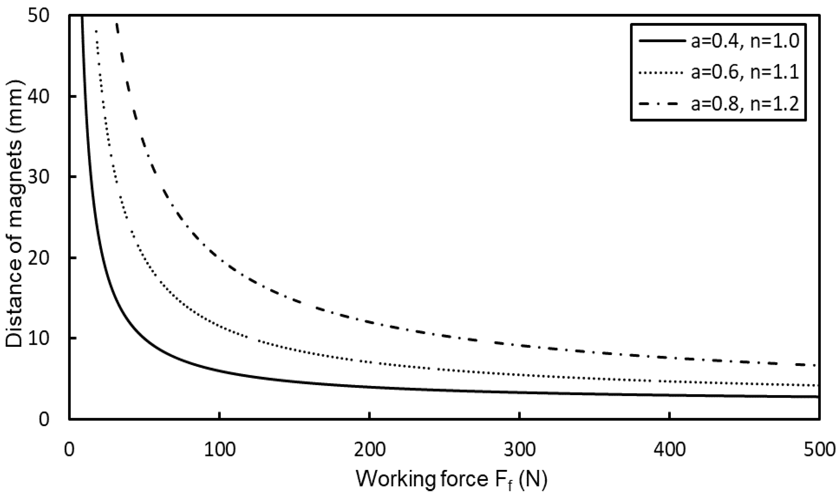
) of the hydraulic cylinder. However, different permanent magnets exhibit different magnetic repulsive force characteristics. We must understand the effect of the hydraulic cylinder working force on the distance between PMs under different PM parameters in order to design a VEAM that can switch modes when the input vibration amplitude is above the specified value. In order to evaluate this, we set the mode switching amplitude
as 0.002 m in this simulation.
Figure 6 presents the relationship between the designed distance between the PMs and the minimum working force of the hydraulic cylinder according to Equation (10). We performed simulations that are based on three kinds of PMs with different magnetic repulsive force characteristics. The solid line represents the curve obtained using the PMs with a = 0.4 and n = 1.0, where a and n are consistent with Equation (9). The dotted line and the dash-dot-dash line represent the curves for when a = 0.6, n = 1.1, and a = 0.8, n = 1.2, respectively. Because the magnet calculation formula involves the power function calculation that may get an infinite value, the ordinate is only taken to an effective distance of 0.05 m.
It can be observed that the three curves show an exponential downward trend as the minimum working force required by the hydraulic cylinder increases, which also reflects the characteristics of the magnet repulsive force. We can also observe that, for the curve with a larger magnetic repulsion factor, the allowable distance between PMs is also greater. Assuming that the minimum working force of the hydraulic cylinder is 200 N, the curve obtained using the magnet repulsive force factor of a = 0.4 and n = 1.0 shows a distance of 0.004 m, which is very close to the preset amplitude value. The reciprocating motion that is caused by vibration is likely to cause the PMs to collide with each other, which may cause damage to the magnet or other components of the VEAM. During the design stage, the allowable distance between PMs should be greater than the preset amplitude to ensure the safety of the system. At the same minimum working force, the allowable distance on the dash-dot-dash curve with a strong magnetic repulsive force is 0.012 m, which is two times higher than the solid curve. Even so, when considering the limitations of geometry and safety factor in actual application, the allowable distance between PMs provided by the simple structural Neodymium magnets (Nd2Fe14B) cannot fully guarantee the safety of the system. However, this work only provides a basis for the design optimization of the VEAM. Based on these methods, we can devise a safer system using stronger magnets in the future by possibly utilizing some sort of motion limiting mechanism or collision prevention buffers between the magnets.
A Simulink model is established using the Simscape module available in Matlab 2019, which is a special numerical simulation software for solving multi-physical problems, in order to verify the automatic switching function between the nonlinear vibration isolator and the hydraulic viscous damper modules.
Figure 7 shows the Simulink model of the entire VEAM subsystem.
Table 1 shows the default parameter values used in this simulation. The nonlinear stiffness isolator module, hydraulic viscous damper module, and the entire VEAM subsystem are simulated separately in order to discuss whether the developed model is valid. In the simulation of the nonlinear stiffness isolator module, the input amplitude and frequency are set at 0.001 m and 1 Hz. In the simulations of hydraulic viscous damper module and the entire VEAM subsystem, the input amplitude and frequency are set at 0.005 m and 1 Hz, respectively. In order to reduce the calculation time, the symmetrically connected hydraulic cylinders are simplified as general viscous damping and the simulation is performed using ode23t solver. No errors or warnings were reported during the entire simulation processes, which shows that each mechanism can operate normally, and that the nonlinear vibration isolator and hydraulic viscous damper can be switched without any problems.
Figure 8 shows the simulation results for the acceleration and the corresponding Fourier spectrum of each mechanism. As shown in
Figure 8a, due to the nonlinear preloading force, the acceleration is relatively large at the beginning, and it tends to gradually reduce to a steady state. It can be seen from the corresponding Fourier spectrum (
Figure 8b) that the acceleration presents a non-linear decreasing curve over the entire bandwidth. When the nonlinear stiffness isolation module is removed and only the hydraulic damping module is operating, the output becomes a familiar damped simple harmonic motion form, this simulation result is shown in
Figure 8c,d. It can be seen from
Figure 8e that the high-frequency harmonics appear at the beginning of the bandwidth and their period cannot be clearly distinguished when the entire VEAM is in a state where the nonlinear stiffness isolation module and the hydraulic damping module operate together. This may be attributed to the nonlinear dynamics of the magnetic force that is generated by the permanent magnets.
Figure 8f plots the corresponding Fourier spectrum implies the visible chaotic phenomenon in the continuous band.
4.2. Non-Linear Stiffness Isolator
When the magnetic repulsive force is less than the minimum working force of the hydraulic cylinder, only the non-linear stiffness vibration isolator composed of the magnetic springs works. In this section, we will individually alter the key parameters of the coil springs and PMs used in the non-linear vibration isolator in order to observe the influence of the parameters , , , and ζ on the vibration isolation performance of the system and summarize the design experience.
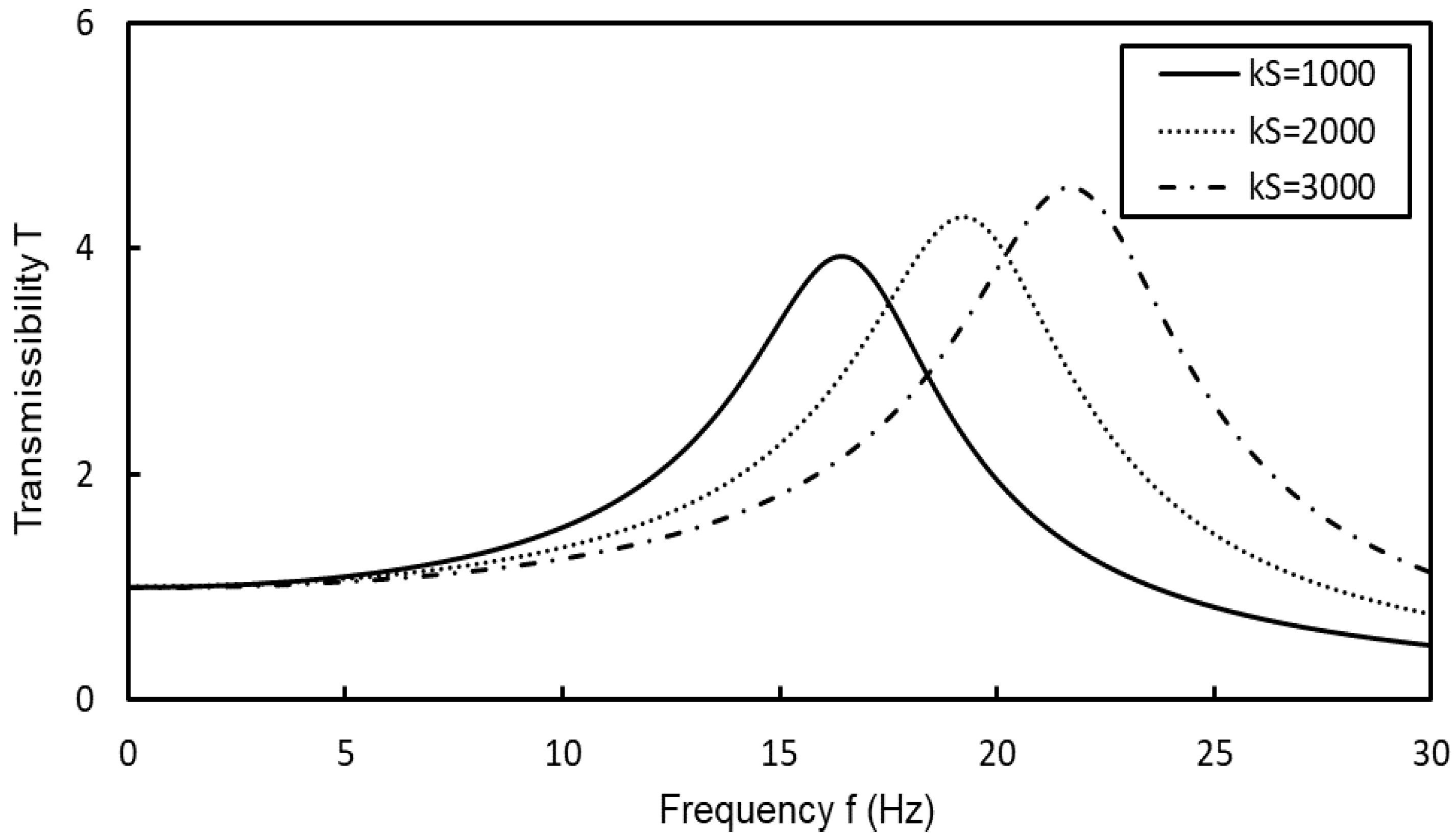
In the first case, the linear stiffness of the coil springs is set as 1000 Nm
−1, 2000 Nm
−1, and 3000 Nm
−1, while the other parameters are kept at the default values that are shown in
Table 1, and the displacement transmissibility of the non-linear stiffness isolator module is observed. The simulation results are shown in
Figure 9. It can be observed that the simulated transmissibility curve moves to the high frequency region with the increase in linear stiffness of the spring. This is accompanied by an increase in the peak value of transmissibility. When the stiffness is 1000 Nm
−1, the maximum displacement transmissibility of 3.9 occurs at a frequency of 16.5 Hz. When the stiffness is 3000 Nm
−1, the maximum displacement transmissibility of 4.5 occurs at a frequency of 21.7 Hz. This shows that increasing the linear stiffness of the spring in the VEAM can effectively reduce the displacement transmissibility in the low frequency region. This means that the vibration isolation performance of the VEAM at a tuning frequency can be optimized using springs with higher stiffness values.
The results of the second case are presented in
Figure 10, which shows the effect of different equivalent linear stiffness obtained using different magnetic springs on the displacement transmissibility of the VEAM. The solid, dotted, and dash-dot-dash curves represent the magnetic spring equivalent linear stiffness values of 2000 Nm
−1, 3500 Nm
−1, and 5000 Nm
−1, respectively. It can be seen that the shifting of the transmissibility curve is similar to that observed while varying the linear stiffness of the spring; i.e., as the equivalent linear stiffness increases the curve shifts to the high frequency region. At frequencies below 18.5 Hz, the VEAM sub-system with a
value of 5000 Nm
−1 has a lower transmissibility than that of the sub-system with a
value of 2000 Nm
−1. At 18.5 Hz, the transmissibility in both cases is equal with a value of 3.2. Beyond this frequency, the transmissibility with a
value of 5000 Nm
−1 becomes higher than that with a
value of 2000 Nm
−1. Therefore, according to these results the VEAM sub-system with larger
value will have better vibration isolation performance in the low frequency range, but it will not work satisfactorily in the high frequency range.
b is the only non-linear stiffness parameter in the VEAM system, so it is necessary to consider its influence on the vibration isolation performance of the whole sub-system. The solid, dotted, and dash-dot-dash curves in
Figure 11 indicate the simulated transmissibility of the VEAM sub-system with respect to b values of 0 (no non-linear stiffness component in the system), default value (8.1 × 10
6), and 10 × 10
9 (an ideal value chosen in order to clearly see the effect of increasing the value), respectively. It can be observed that, as the value of b increases, the peak value of the transmissibility decreases and shifts towards the high-frequency region. However, the curve appears to bend to the right and, as the value of b gets larger, the amount of bending also becomes greater (as shown in the dash-do-dash curve). A similar sort of transmissibility curve bending towards the high frequency region has also been reported in other works [
40,
41]. We speculate that the excessive curve bending caused by the large b value will cause multiple transmissibility values to exist in a part of the frequency range, which means that there will be a multiple states phenomenon. This may cause the dynamics of the system to become complicated with the change in amplitude and frequency of excitation and chaotic motion may occur, as shown in
Figure 8b.
In the non-linear stiffness isolator module consisting of a magnetic spring, there is no additional damping, except for the structural damping of the springs. We simulated the transmissibility of the VEAM sub-system with spring structural damping ratios of 0.02, 0.04, and 0.06.
Figure 12 shows the results of these simulations. It can be observed that, the larger the structural damping ratio, the smaller the transmissibility of the VEAM sub-system. It is also apparent that the structural damping has almost no effect on the change of the frequency domain of the peak transmissibility value. When the frequency is 13.0 Hz, the maximum transmissibility of the sub-system with a spring structural damping ratio of 0.06 is 65.2% lower than that with a structural damping ratio of 0.02. This result shows that structural damping has a considerable effect on the overall vibration damping characteristic of the system.
4.3. Hydraulic Damper
Under normal conditions, the stay cable vibration has a small amplitude. However, under special environmental impacts, such as earthquakes and typhoons, the amplitude of the stay cable vibration can become large. The VEAM incorporates hydraulic viscous dampers in its design to dampen such large amplitude vibrations by exploiting their high damping performance. This section explores the effects of damping and spring stiffness on the performance of this damper module. In this section, the excitation amplitude is set as 0.005 m.
In practical applications, the damping ratio of the hydraulic damper used in VEAM can be adjusted by changing the size of the orifice in the flow path. To make performance comparisons, we set the damping ratios of the hydraulic cylinders at 0.2, 0.6, and 0.8.
Figure 13 shows the simulated transmissibility results of the VEAM sub-system. It can be seen that the higher the damping ratio of the hydraulic cylinder the lower the peak value of the transmissibility. However, although the curve with the lowest damping ratio of 0.2 has a higher transmissibility in the low-frequency region (region of amplification) within a characteristic frequency, the frequency region after this frequency, which is called the “isolation region”, shows better vibration isolation performance.
Figure 14 shows a comparison of the simulated transmissibility with varying values of
. Similar to
Figure 9, the frequency domain of the peak wave of transmissibility curve becomes wider as the value of
increases, and the maximum transmissibility occurs at a higher frequency. However, the difference between the two figures is that the peak value of the transmissibility is not affected by the change in the value of
. This is because, when the hydraulic shock absorber is in operation, the magnetic spring stops working, and the equivalent stiffness of the entire system no longer changes due to the nonlinear stiffness. Thus, for the damping module, the spring with a lower
value shows better isolation performance in the high frequency region.


