Article

A Blockchain-Based Secure Inter-Hospital EMR Sharing System

1
College of Computer and Information Engineering, Xiamen University of Technology, Xiamen 361024, China
2
School of Information Engineering, Changchun Sci-Tech University, Changchun 130600, China
3
Department of Computer Science and Information Engineering, Chaoyang University of Technology, Taichung 413310, Taiwan
4
Department of Computer Science, Jilin Normal University, Siping 136000, China
*
Authors to whom correspondence should be addressed.
Appl. Sci. 2020, 10(14), 4958; https://doi.org/10.3390/app10144958
Submission received: 31 May 2020 / Revised: 5 July 2020 / Accepted: 15 July 2020 / Published: 19 July 2020
(This article belongs to the Special Issue Novel Algorithms and Protocols for Networks)

Abstract

:
In recent years, blockchain-related technologies and applications have gradually emerged. Blockchain technology is essentially a decentralized database maintained by the collective, and it is now widely applied in various fields. At the same time, with the growth of medical technology, medical information is becoming increasingly important in terms of patient identity background, medical payment records, and medical history. Medical information can be the most private information about a person, but due to issues such as operation errors within the network or a hacking attack by a malicious person, there have been major leaks of sensitive personal information in the past. In any case, this has become an issue worth studying to ensure the privacy of patients and protect these medical materials. On the other hand, under the current medical system, the patient’s EMR (electronic medical record) cannot be searched across the hospital. When the patient attends the hospital for treatment, repeated examinations will occur, resulting in a waste of medical resources. Therefore, we propose a blockchain-based secure inter-hospital EMR sharing system in this article. Through the programmatic authorization mechanism by smart contracts, the security of EMR is guaranteed. In addition to the essential mutual authentication, the proposed scheme also provides and guarantees data integrity, nonrepudiation, user untraceability, forward and backward secrecy, and resistance to replay attack.

1. Introduction

Background

With the rapid growth of information technology, our lives are more convenient now than in the past. Our surroundings are full of IT-related services and applications; one of them is medical diagnosis and treatment services. In order to implement the long-term development goals of medical diagnosis and treatment, the government focuses on livelihood issues such as protection of medical information, medical payment, medical data application, medical data storage sharing, medical information transactions, and predictive analysis [1,2,3,4,5]. In order to achieve these goals, some technologies, such as data protection, encryption, and cloud computation, are used [6,7,8,9,10].
At the same time, with the growth of medical technology, medical information is becoming increasingly important in terms of patient identity background, medical payment records, and medical history. In the past, medical records were transmitted through paper, and with the development of technology, these medical records were electronically stored in private servers in hospitals [11,12,13,14,15]. Medical information can be the most private information about a person, but due to issues such as operation errors within the network or a hacking attack by a malicious person, there have been major leaks of sensitive personal information in the past [16,17,18,19,20]. In any case, this has become an issue worth studying in order to ensure the privacy of patients and protect these medical materials.
On the other hand, under the current medical system, the patient’s medical record cannot be searched across the hospital. For example, when a patient is originally diagnosed and treated in hospital A, and then visits hospital B, hospital B must perform the same examination again, resulting in a waste of medical resources. Furthermore, when a patient seeks medical treatment, the physician does not know the medical history of the patient relating to other hospital visits in the past, and this also increases the medical risk and reduces the accuracy of the diagnosis [21,22,23,24,25]. Therefore, inter-hospital medical record access is a very important goal.
Besides this, blockchain-related technologies and applications have gradually emerged in recent years [26,27,28,29,30]. Blockchain technology is essentially a decentralized database maintained by the collective. It has the characteristics of high reliability and high confidentiality and has the strong prospect of effectively solving the trust problem between the two parties. Credit is the basis for the production and maintenance of social relations between people and organizations. At present, people mainly use regulations, systems, laws, contractual agreements, etc. to restrict credit problems. These methods cannot solve credit problems because of many subjective factors. The decentralization of the blockchain allows all users who join the blockchain to participate in the data authenticity proof, abandoning the shortcomings of the traditional certification system, the single certification center [31,32,33,34].
According to the WHO (World Health Organization) forum [35], the emergence of blockchain technology has provided solutions for medical resource management in recent days. Blockchain technology allows hospitals, patients, and other parties to share data within the blockchain, without worrying about the security and integrity of the data [36,37,38]. Through smart contracts, patients can authorize medical staff to access their medical information, so that medical staff can understand this information and provide better care services. Moreover, through blockchain technology, the patient’s EMR (electronic medical record) is directly obtained from the server of the original hospital, so the content of the EMR will not be limited to a specific format. Compared with the current EMR sharing mode [39,40], better integrity and timeliness can be achieved with this method.
Although some scholars have previously proposed secure medical systems, there is still a lack of security mechanisms for an inter-hospital medical system [41,42,43,44]. Therefore, we propose a blockchain-based secure inter-hospital EMR sharing system in this article. When the patient visits hospital A to seek medical services, hospital A will store medical records in the server of hospital A, and hospital A will also inform the patient about the results. When the patient goes to hospital B to seek further medical diagnosis or treatment, hospital B can obtain the previous medical records from hospital A without conducting the same examination again. This can prevent the waste of medical resources and achieve higher medical quality and efficiency. It achieves security, privacy, and efficiency in the proposed inter-hospital medical system [45,46].
The remainder of this article is arranged as follows. Section 2 shows the preliminary and security requirements of the proposed blockchain-based secure inter-hospital EMR sharing system. Section 3 shows the proposed blockchain-based secure inter-hospital EMR sharing system. Section 4 shows the security and efficiency analysis of the proposed scheme. Section 5 offers conclusions.

2. Preliminary and Security Requirements

2.1. Preliminary

2.1.1. BAN Logic Model

The Burrows–Abadi–Needham (BAN) logic proof model [47] is usually applied to prove the correctness of a protocol or scheme. The BAN logic proof model has been widely applied by many security-related articles to prove whether the proposed protocol or scheme achieves mutual authentication. The following descriptions are the BAN logic-related notations:
P | X : P trusts X , or P is qualified to trust X .
P X : P catches sight of X . P can review and duplicate X , when somebody sends P a message that contains X .
P | ~ X : P said X before. P sometimes sent a message that included X .
P | X : P has jurisdiction over X . It should be trusted that P is an authority on X .
< X > Y :This indicates that X combined with Y .
# ( X ) : X is the latest, which means X has never been sent previously.
P K Q :The shared key K is used for communication by P and Q .
P S Q :Only P , Q , and their trusted subjects know the secret S .

2.1.2. Elliptic Curve Group

Digital network systems are essential technologies in our daily life, with large amounts of documents and information being transmitted and exchanged over them. Thus, it is very important to guarantee the security of these transmitted and exchanged messages. To ensure the security of these important documents and messages, several digital encryption systems have therefore been proposed by researchers. The elliptic curve cryptography [48] was proposed in 1985, and the length of its message is shorter than that of the Rivest–Shamir–Adleman (RSA) encryption system. A brief introduction to the elliptic curve group technology and its corresponding difficultly mathematical problems as follows:
Allowing F q to be a prime finite field, E / F q is an elliptic curve defined over the prime finite field F q , and P is a generator for a cyclic additive group of the composite order q . The point on E / F q is together with an extra point Θ , which is called the point at infinity, and it forms a group G = { ( x , y ) : x , y F q ; ( x , y ) E / F q } { Θ } . G is a cyclic additive group of composite order q . Scalar multiplication over E / F q can be computed as t P = P + P + + P , which is added t times.
The following problems exist for the elliptic curve Diffie–Hellman (ECDH) method:
Computational Diffie–Hellman (CDH) Problem: a P and b P are given first, and where a , b R . Z q * and P are the generators of G , the value a b P is computed.
Decisional Diffie–Hellman (DDH) Problem: a P , b P and c P are given first, and where a , b , c R . Z q * and P are the generators of G , then whether c P = a b P or not is confirmed, and this is equal to confirming whether c = a b mod q or not.

2.1.3. Smart Contract

The smart contract was proposed by Nick Szabo [49], a cross-disciplinary legal scholar, and it can be traced back to 1995. The following is the definition of a smart contract: a smart contract is a set of promises defined in digital form, including contract participants. The promised agreement can be executed on it. Blockchain technology can achieve collaboration and trust between multiple enterprise entities through smart contracts, thereby expanding the scope and depth of mutual cooperation between parties.
With the development of medical technology, medical data records a large amount of information about the patient’s identity background, medical history, and medical payment records. Blockchain technology can record and encrypt medical records, as in bookkeeping. The records are kept by patients themselves and can be used at any time when they visit different medical institutions, which fully guarantees privacy and security. Through the smart contract, patients can authorize medical staff to access their medical information, so that medical staff can examine this information and provide better care services.

2.2. Security Requirements

The following list shows the security requirements for a blockchain-based secure inter-hospital EMR sharing system [28,29,30,31,32,33,34].

2.2.1. Mutual Authentication

The information receiver must be capable of confirming the legal identity of the information’s sender during the message transmission process. Therefore, each party must be able to confirm the legal identity of the other party in an EMR sharing system environment. If any two parties can confirm one another’s legal identity, then the proposed system achieves mutual authentication.

2.2.2. Data Integrity

The system is vulnerable to malicious attacks in the form of modification for any message transmitted in an unencrypted network environment. This means that the information delivered to the receiver is not the original information transferred by the sender. Therefore, the integrity of the transferred message must be ensured, and the message must also be protected against tampering during the transmission.

2.2.3. User Untraceability

Malicious attackers may also try to trace a person’s mobile device, and they can then determine his/her physical location. Therefore, a blockchain-based secure inter-hospital EMR sharing system must prevent such positional tracking.

2.2.4. Resisting Replay Attacks

The transmitted information between the personal mobile device and the hospital medical device may also be intercepted by malicious attackers, and then malicious attackers can impersonate a legitimate transmitter and send the same information to the predetermined receiver. Such a condition represents a critical gap in personal data security and therefore must be prevented in a blockchain-based secure inter-hospital EMR sharing system.

2.2.5. Forward and Backward Secrecy

If a malicious attacker compromises the session key which is established between the personal mobile device and the hospital medical device, he/she may use the compromised session key for future malicious communications or to obtain previously transmitted messages. A blockchain-based secure inter-hospital EMR sharing system thus ought to achieve forward and backward secrecy.

2.2.6. Non-Repudiation

When the receiver receives the message sent by the sender, the sender may deny sending the message. Therefore, the message sent by the sender must be signed with the secret key of the sender. The receiver can verify the received message with the public key of the sender, and then the sender cannot deny sending the message. A blockchain-based secure inter-hospital EMR sharing system should thus achieve nonrepudiation.

3. The Proposed Scheme

3.1. System Architecture

The framework of the blockchain-based secure inter-hospital EMR sharing system is shown in Figure 1 [50,51].
There are four parties in the scheme:
(1)
Blockchain Center: The blockchain center belongs to the government medical institution. The blockchain center manages all personal mobile devices and hospital medical devices. All patients and hospitals must register in the blockchain center with their mobile devices and hospital medical devices, then the patient and the hospital can authenticate each other.
(2)
Patient: The patient carries a personal mobile device. The personal mobile device stores verification messages about the identity of the patient. After this, when the patient visits the hospital to seek medical services, the hospital and the patient can achieve mutual authentication through the personal mobile device. Thus, the personal mobile device can also hold the medical index of the hospital that was visited previously and will be provided to other hospitals in the future as an index for medical records.
(3)
Hospital A: The doctor uses a medical device in hospital A. When the patient visits hospital A with a symptom, hospital A and the patient will verify one another’s identity first. After this, hospital A will diagnose the patient. Hospital A will store medical records in the server of hospital A, and hospital A will also inform the patient about the results. The patient keeps the diagnostic results and medical index in his/her mobile device.
(4)
Hospital B: The doctor uses a medical device in hospital B. When the patient goes to hospital B to extend treatment for a symptom that was previously diagnosed in hospital A, hospital B and the patient will also verify one another’s identity first. After this, hospital B will obtain the medical index of hospital A from the personal mobile device of the patient. Then, hospital B will request the patient’s medical records from hospital A. After diagnosis, hospital B will store medical records in the server of hospital B, and hospital B will also inform the patient about the results. The patient keeps the diagnostic results and medical index in his/her mobile device.
Figure 1. The framework of the blockchain-based secure inter-hospital EMR sharing system.
Applsci 10 04958 g001
  • All personal mobile devices carried by patients and all medical devices used by hospital A and hospital B must be registered in the blockchain center through a secure channel. The patient, hospital A, and hospital B send their universally unique IDs to the blockchain center. The blockchain center returns information that includes parameters calculated by elliptic curve group technology.
  • When the patient carries his/her mobile device to hospital A to seek medical services, hospital A and the patient must authenticate one another’s identity first. After mutual authentication between the patient and hospital A, the doctor of hospital A diagnoses the patient. After diagnosis, the doctor of hospital A stores the medical records of the patient in the server of hospital A, and the doctor of hospital A will also inform the patient about the results. The patient keeps the diagnostic results and medical index in his/her mobile device.
  • When the patient carries his/her mobile device and visits hospital B for extended treatment of a symptom that was previously diagnosed in hospital A, hospital B and the patient will also verify one another’s identity first. After mutual authentication between the patient and hospital B, the doctor of hospital B obtains the medical index of hospital A from the personal mobile device of the patient. Then, the doctor of hospital B requests the medical records of the patient from hospital A. After the doctor of hospital B obtains the encrypted medical records from hospital A and performs a diagnosis, the doctor of hospital B stores the medical records of the patient in the server of hospital B. The doctor of hospital B also informs the patient about the results. The patient keeps the diagnostic results and medical index in his/her mobile device.

3.2. System Initialization Phase

In the system’s initialization stage, the blockchain center calculates some parameters and publishes the public parameters for patients with personal mobile devices and hospitals with medical devices.
Step 1:
The blockchain center chooses a k -bit prime, p , and determines the tuple of the elliptic curve group ( F p , E / F p , G , P ) .
Step 2:
The blockchain center then chooses s as a secret key and computes
P K = s P ,
as a public key.
Step 3:
Finally, the blockchain center chooses a hash function ( H 1 ( ) , H 2 ( ) , H 3 ( ) ) and then publishes ( F p , E / F p , G , P , P K , H 1 ( ) , H 2 ( ) , H 3 ( ) ) to all patients with personal mobile devices and hospitals with medical devices.

3.3. Smart Contract Initialization

In the proposed architecture, blockchain technology is applied. During the medical treatment process, some key information will be saved and verified through the blockchain. The key information in the blockchain is defined in the smart contract. The following is the blockchain smart contract structure for medical treatment information.
struct patient information smart contract ptinf{
    string patient id;
    string patient detail;
    mapping medical record;
}
struct hospital A information smart contract hainf{
    string hospital A id;
    string hospital A detail;
}
struct hospital B information smart contract hbinf{
    string hospital B id;
    string hospital B detail;
}
struct medical record smart contract mrinf{
    string diagnosis id;
    string diagnosis detail;
}
In the proposed smart contract, we have developed key information that will be stored in the blockchain. In the structure of the patient information smart contract, we developed the field of patient ID (identification), patient detail, and mapping to the medical record. In the structure of the hospital A smart contract, we developed the fields of hospital A ID and hospital A detail. In the structure of the hospital B smart contract, we developed the fields of hospital B ID and hospital B detail. In the structure of the medical record smart contract, we developed the fields of diagnosis ID and diagnosis detail. In the initialization phase, the blockchain center also issues the public and private key pairs for all roles. Besides this, there will be a variable that records the current blockchain state in the blockchain smart contract architecture.

3.4. Patient Registration Phase

The patient mobile device carried by the patient must register with the blockchain center. At this stage, the patient registers with the blockchain center and obtains the public and private keys for message signatures and key messages for encryption. When the patient registers with the blockchain center, the blockchain center will add the registration information of the patient to the blockchain through a smart contract. The patient registration phase of the proposed scheme is demonstrated in Figure 2.
Step 1:
The patient chooses his/her universally unique identity, I D P A T , and sends it to the blockchain center.
Step 2:
The blockchain center chooses a random number, r P A T , and calculates
R P A T = r P A T P ,
h P A T = H 1 ( I D P A T , R P A T ) ,
S P A T = r P A T + h P A T s ,
If the identity I D P A T is valid, the blockchain center calls the smart contract ptins as follows:
function patient insert smart contract ptins(
string patient id, string patient detail,
mapping medical record) {
    count ++;
    patient id. count = id;
    patient detail. count = detail;
    mapping medical record = null;
}
string patient keypairs;
and it then sends ( R P A T , S P A T , P K P A T , S K P A T ) to the patient.
Step 3:
The patient verifies
S P A T P = ? R P A T + H 1 ( I D P A T , R P A T ) P K .
If the verification is passed, then the patient stores ( R P A T , S P A T , P K P A T , S K P A T ) in his/her mobile device.

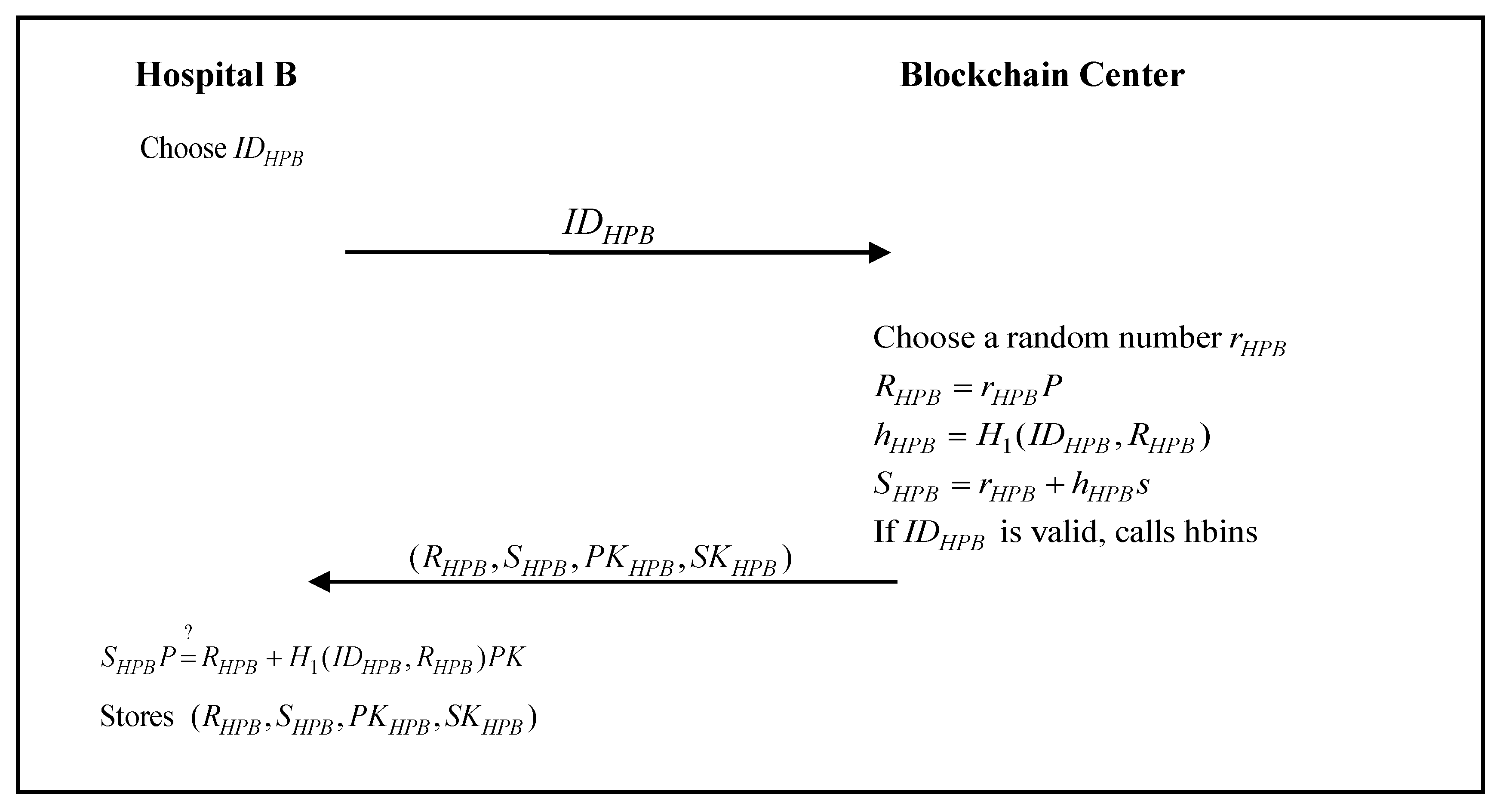
3.5. Hospital Registration Phase

The medical device used by hospital A or hospital B must register with the blockchain center. At this stage, hospital A or hospital B registers with the blockchain center and obtains the public and private keys for message signatures and key messages for encryption. When hospital A or hospital B registers with the blockchain center, the blockchain center will add the registration information of hospital A or hospital B to the blockchain through the smart contract. The hospital registration phase of the proposed scheme is shown in Figure 3 and Figure 4.
Figure 3. The hospital A registration phase of the proposed scheme.
Applsci 10 04958 g003
Step 1:
Hospital A chooses a unique identity, I D H P A , and sends it to the blockchain center.
Step 2:
The blockchain center chooses a random number, r H P A , and calculates
R H P A = r H P A P ,  
h H P A = H 1 ( I D H P A , R H P A ) ,
S H P A = r H P A + h H P A s ,
If the identity I D H P A is valid, the blockchain center calls the smart contract hains as follows:
function hospital A insert smart contract hains(
string hospital A id, string hospital A detail) {
    count ++;
    hospital A id. count = id;
    hospital A detail. count = detail;
}
string hospital A keypairs;
and it then sends ( R H P A , S H P A , P K H P A , S K H P A ) to hospital A.
Step 3:
Hospital A verifies
S H P A P = ? R H P A + H 1 ( I D H P A , R H P A ) P K .
If the verification passes, then hospital A stores ( R H P A , S H P A , P K H P A , S K H P A ) in the medical device.
Figure 4. The hospital B registration phase of the proposed scheme.
Applsci 10 04958 g004
Step 1:
Hospital B chooses a unique identity, I D H P B , and sends it to the blockchain center.
Step 2:
The blockchain center chooses a random number, r H P B , and calculates
R H P B = r H P B P ,
h H P B = H 1 ( I D H P B , R H P B ) ,
S H P B = r H P B + h H P B s ,
If the identity I D H P B is valid, the blockchain center calls the smart contract hbins as follows:
function hospital B insert smart contract hbins(
string hospital B id, string hospital B detail) {
    count ++;
    hospital B id. count = id;
    hospital B detail. count = detail;
}
string hospital B keypairs;
and it then sends ( R H P B , S H P B , P K H P B , S K H P B ) to hospital B.
Step 3:
Hospital B verifies
S H P B P = ? R H P B + H 1 ( I D H P B , R H P B ) P K .
If the verification passes, then hospital B stores ( R H P B , S H P B , P K H P B , S K H P B ) in the medical device.

3.6. Initial Treatment Authentication and Communication Phase

When the patient carries his/her mobile device to hospital A to seek medical services, hospital A and the patient must authenticate one another’s identity first. After mutual authentication between the patient and hospital A, the doctor of hospital A diagnoses the patient. After diagnosis, the doctor of hospital A stores the medical records of the patient in the server of hospital A, and the doctor of hospital A will also inform the patient about the results. The patient keeps the diagnostic results and medical index in his/her mobile device. The initial treatment authentication and communication phase of the proposed scheme is shown in Figure 5.
Step 1:
The patient chooses a random number, a , calculated by
T P A T = a P
and then sends ( I D P A T , R P A T , T P A T ) to hospital A.
Step 2:
Hospital A chooses a random number, b , calculated by
T H P A = b P ,
P K P A T = R P A T + H 1 ( I D P A T , R P A T ) P K ,
K A P 1 = S H P A T P A T + b P K P A T ,
K A P 2 = b T P A T ,
and the session key
S E K A P = H 2 ( K A P 1 , K A P 2 ) .
Hospital A then calculates
C H K P A = H 3 ( S E K A P , T P A T ) ,
and sends ( I D H P A , R H P A , T H P A , C H K P A ) to the patient.
Step 3:
The patient calculates
P K H P A = R H P A + H 1 ( I D H P A , R H P A ) P K ,
K P A 1 = S P A T T H P A + a P K H P A ,
K P A 2 = a T H P A ,
and the session key
S E K A P = H 2 ( K P A 1 , K P A 2 ) .
The patient then verifies
C H K P A = ? H 3 ( S E K A P , T P A T )
to check the legality of hospital A. If the verification passes, the patient calls the smart contract hachk as follows:
function hospital A check smart contract hachk(
    string hospital A id,
    string hospital A detail) {
    return hospital A id. exist;
    return hospital A detail. exist;
}
The patient then calculates
c P A T = E S E K A P ( m e s s a g e )
C H K A P = H 3 ( S E K A P , T H P A )
and sends ( I D P A T , c P A T , C H K A P ) to hospital A.
Step 4:
Hospital A verifies
C H K A P = ? H 3 ( S E K A P , T H P A ) ,
to check the legality of the patient. If the verification passes, the session key S E K A P between the patient and hospital A is established successfully. Hospital A calls the smart contract ptchk as follows:
    return patient id. exist;
    return patient detail. exist;
    mapping medical record. exist;
}
function patient check smart contract ptchk(
    string patient id,
    string patient detail,
    mapping medical record) {
Hospital A then decrypts the received message
m e s s a g e = D S E K A P ( c P A T ) ,
to obtain the information about the patient’s symptoms. After the diagnosis of the patient, hospital A stores the medical records of the patient in the server and generates the encrypted basic inspection report and certificate C e r t H P A
c H P A = E S E K A P ( E M R , C e r t H P A ) ,
S i g H P A = S S K H P A ( E M R , C e r t H P A ) ,
If the identity I D P A T is valid, the hospital A calls the smart contract mrins and ptins as follows:
function patient insert smart contract ptins(
string patient id, string patient detail,
mapping medical record) {
    mapping medical record = medical record;
}
sign string hospital A key (
medical record);
function medical record insert smart contract mrins(
string diagnosis id, string diagnosis detail) {
    count ++;
    diagnosis id. count = id;
    diagnosis detail. count = detail;
}
and sends ( I D H P A , c H P A , S i g H P A ) to the patient.
Step 5:
The patient decrypts the received message,
( E M R , C e r t H P A ) = D S E K A P ( c H P A ) ,
verifies the signature,
( E M R , C e r t H P A ) = ? V P K H P A ( S i g H P A ) .
and receives the encrypted basic inspection report from hospital A.

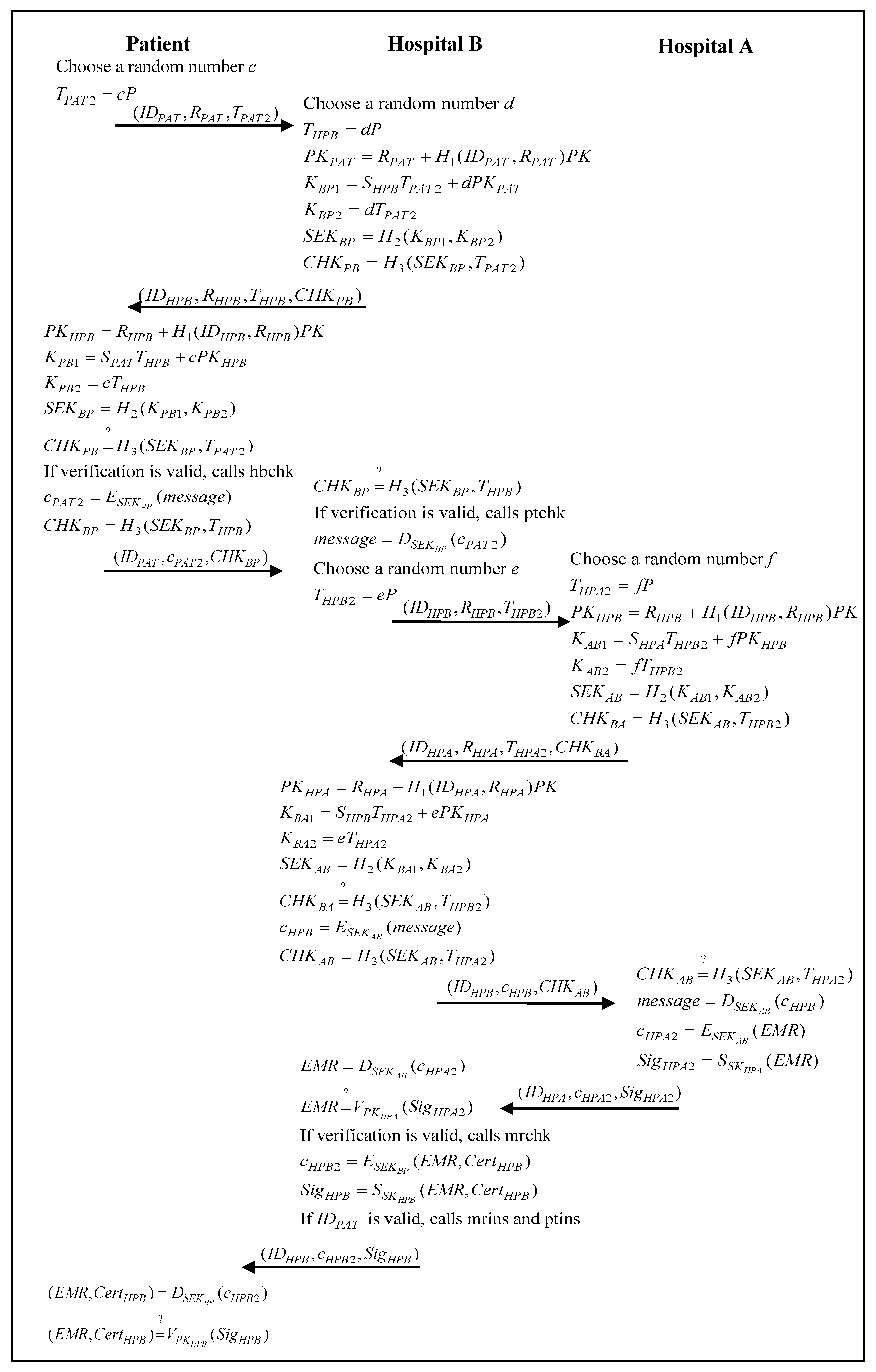
3.7. Inter-Hospital Authentication and Communication Phase

When the patient carries his/her mobile device and visits hospital B for extended treatment of a symptom that was previously diagnosed in hospital A, hospital B and the patient will also verify one another’s identity first. After mutual authentication between the patient and hospital B, the doctor of hospital B obtains the medical index of hospital A from the personal mobile device of the patient. Then, the doctor of hospital B requests the medical records of the patient from hospital A. After the doctor of hospital B obtains the encrypted medical records from hospital A and performs a diagnosis, the doctor of hospital B stores the medical records of the patient in the server of hospital B. The doctor of hospital B also informs the patient about the results. The patient keeps the diagnostic results and medical index in his/her mobile device. The inter-hospital authentication and communication phase of the proposed scheme is shown in Figure 6.
Step 1:
The patient chooses a random number, c , calculated by
T P A T 2 = c P ,
and then sends ( I D P A T , R P A T , T P A T 2 ) to hospital B.
Step 2:
Hospital B chooses a random number, d , calculated by
T H P B = d P ,
P K P A T = R P A T + H 1 ( I D P A T , R P A T ) P K ,
K B P 1 = S H P B T P A T 2 + d P K P A T ,
K B P 2 = d T P A T 2 ,
and the session key,
S E K B P = H 2 ( K B P 1 , K B P 2 ) .
Hospital B then calculates
C H K P B = H 3 ( S E K B P , T P A T 2 ) ,
and sends ( I D H P B , R H P B , T H P B , C H K P B ) to the patient.
Step 3:
The patient calculates
P K H P B = R H P B + H 1 ( I D H P B , R H P B ) P K ,
K P B 1 = S P A T T H P B + c P K H P B ,
K P B 2 = c T H P B ,
and the session key,
S E K B P = H 2 ( K P B 1 , K P B 2 ) .
The patient then verifies
C H K P B = ? H 3 ( S E K B P , T P A T 2 )
to check the legality of hospital B. If the verification passes, the patient calls the smart contract hbchk as follows:
function hospital B check smart contract hbchk(
    string hospital B id,
    string hospital B detail) {
    return hospital B id. exist;
    return hospital B detail. exist;
}
The patient then calculates
c P A T 2 = E S E K B P ( m e s s a g e )
C H K B P = H 3 ( S E K B P , T H P B )
and sends ( I D P A T , c P A T 2 , C H K B P ) to hospital B.
Step 4:
Hospital B verifies
C H K B P = ? H 3 ( S E K B P , T H P B ) ,
to check the legality of the patient. If the verification is passed, the session key S E K B P between the patient and hospital B is established successfully. The hospital B calls the smart contract ptchk as follows:
function patient check smart contract ptchk(
    string patient id,
    string patient detail,
    mapping medical record) {
    return patient id. exist;
    return patient detail. exist;
    mapping medical record. exist;
}
Hospital B then decrypts the received message
m e s s a g e = D S E K B P ( c P A T 2 ) ,
and receives the encrypted diagnostic results and medical index from hospital A. Hospital B then requests the medical records of the patient from hospital A.
Step 5:
Hospital B chooses a random number, e , calculated by
T H P B 2 = e P ,
and then sends ( I D H P B , R H P B , T H P B 2 ) to hospital A.
Step 6:
Hospital A chooses a random number, f , calculated by
T H P A 2 = f P ,
P K H P B = R H P B + H 1 ( I D H P B , R H P B ) P K ,
K A B 1 = S H P A T H P B 2 + f P K H P B ,
K A B 2 = f T H P B 2 ,
and the session key,
S E K A B = H 2 ( K A B 1 , K A B 2 )
Hospital A then calculates
C H K B A = H 3 ( S E K A B , T H P B 2 ) ,
and sends ( I D H P A , R H P A , T H P A 2 , C H K B A ) to hospital B.
Step 7:
Hospital B calculates
P K H P A = R H P A + H 1 ( I D H P A , R H P A ) P K
K B A 1 = S H P B T H P A 2 + e P K H P A ,
K B A 2 = e T H P A 2 ,
and the session key,
S E K A B = H 2 ( K B A 1 , K B A 2 ) .
Hospital B then verifies
C H K B A = ? H 3 ( S E K A B , T H P B 2 )
to check the legality of hospital A. If the verification passes, hospital B calculates
c H P B = E S E K A B ( m e s s a g e )
C H K A B = H 3 ( S E K A B , T H P A 2 )
and sends ( I D H P B , c H P B , C H K A B ) to hospital A.
Step 8:
Hospital A verifies
C H K A B = ? H 3 ( S E K A B , T H P A 2 )
to check the legality of hospital B. If the verification is passed, the session key S E K A B between hospital B and hospital A is established successfully.
Hospital A then decrypts the received message
m e s s a g e = D S E K A B ( c H P B )
and receives the medical record request from the patient. Hospital A then generates the encrypted medical records of the patient
c H P A 2 = E S E K A B ( E M R ) ,
S i g H P A 2 = S S K H P A ( E M R ) ,
and sends ( I D H P A , c H P A 2 , S i g H P A 2 ) to hospital B.
Step 9:
Hospital B decrypts the received message
E M R = D S E K A B ( c H P A 2 ) ,
verifies the signature,
E M R = ? V P K H P A ( S i g H P A 2 ) .
If the verification passes, and hospital B calls the smart contract mrchk as follows:
string diagnosis id,
string diagnosis detail) {
    return diagnosis id. exist;
    return diagnosis detail. exist;
}
verify string hospital A key (
hospital A information,
patient information);
function medical record check smart contract mrchk(
Hospital B then receives the encrypted medical records of the patient from hospital A.
Step 10:
After the diagnosis of the patient, hospital B stores the medical records of the patient in the server and generates the encrypted basic inspection report
c H P B 2 = E S E K B P ( E M R , C e r t H P B ) ,
S i g H P B = S S K H P B ( E M R , C e r t H P B ) ,
If the identity I D P A T is valid, hospital B calls the smart contract mrins and ptins as follows:
function patient insert smart contract ptins(
string patient id, string patient detail,
mapping medical record) {
    mapping medical record = medical record;
}
sign string hospital B key (
medical record);
function medical record insert smart contract mrins(
string diagnosis id, string diagnosis detail) {
    count ++;
    diagnosis id. count = id;
    diagnosis detail. count = detail;
}
and sends ( I D H P B , c H P B 2 , S i g H P B ) to the patient.
Step 11:
The patient decrypts the received message,
( E M R , C e r t H P B ) = D S E K B P ( c H P B 2 ) ,
verifies the signature,
( E M R , C e r t H P B ) = ? V P K H P B ( S i g H P B ) .
and receives the encrypted basic inspection report from hospital B.

4. Security Analysis

4.1. Mutual Authentication

The BAN logic proof model is applied in order to prove that mutual authentication is achieved between different parties in each phase of the proposed scheme.
In the initial treatment authentication and communication phase of the proposed scheme, the main goal of the scheme is to authenticate the session key establishment between the patient, P, and hospital A, HA.
G1: P | P S E K A P H A
G2: P | H A | P S E K A P H A
G3: H A | P S E K A P H A
G4: H A | P | P S E K A P H A
G5: P | I D H P A
G6: P | H A | I D H P A
G7: H A | I D P A T
G8: H A | P | I D P A T
According to the initial treatment authentication and communication phase, BAN logic is applied in order to produce an idealized form as follows:
M1: ( < I D P A T , R P A T , T P A T > P K H P A , < H ( S E K A P , T H P A ) > C H K A P )
M2: ( < I D H P A , R H P A , T H P A > P K P A T , < H ( S E K A P , T P A T ) > C H K P A )
To analyze the proposed scheme, the following assumptions are made:
A1: P | # ( T P A T )
A2: H A | # ( T P A T )
A3: P | # ( T H P A )
A4: H A | # ( T H P A )
A5: P | H A | P S E K A P H A
A6: H A | P | P S E K A P H A
A7: P | H A | I D H P A
A8: H A | P | I D P A T
According to these assumptions and the rules of BAN logic, the main proof of the initial treatment authentication and communication phase is as follows:
  • Hospital A, HA, authenticates the patient, P.
    We derive the following statement by M1 and the seeing rule:
    H A ( < I D P A T , R P A T , T P A T > P K H P A , < H ( S E K A P , T H P A ) > C H K A P ) (Statement 1)
    We derive the following statement by A2 and the freshness rule:
    H A | # ( < I D P A T , R P A T , T P A T > P K H P A , < H ( S E K A P , T H P A ) > C H K A P ) (Statement 2)
    We derive the following statement by (Statement 1), A4, and the message meaning rule:
    H A | P | ~ ( < I D P A T , R P A T , T P A T > P K H P A , < H ( S E K A P , T H P A ) > C H K A P ) (Statement 3)
    We derive the following statement by (Statement 2), (Statement 3), and the nonce verification rule:
    H A | P | ( < I D P A T , R P A T , T P A T > P K H P A , < H ( S E K A P , T H P A ) > C H K A P ) (Statement 4)
    We derive the following statement by (Statement 4) and the belief rule:
    H A | P | P S E K A P H A (Statement 5)
    We derive the following statement by (Statement 5), A6, and the jurisdiction rule:
    H A | P S E K A P H A (Statement 6)
    We derive the following statement by (Statement 6) and the belief rule:
    H A | P | I D P A T (Statement 7)
    We derive the following statement by (Statement 7), A8, and the jurisdiction rule:
    H A | I D P A T (Statement 8)
  • The patient P authenticates the hospital A HA.
    We derive the following statement by M2 and the seeing rule:
    P ( < I D H P A , R H P A , T H P A > P K P A T , < H ( S E K A P , T P A T ) > C H K P A ) (Statement 9)
    We derive the following statement by A1 and the freshness rule:
    P | # ( < I D H P A , R H P A , T H P A > P K P A T , < H ( S E K A P , T P A T ) > C H K P A ) (Statement 10)
    We derive the following statement by (Statement 9), A3, and the message meaning rule:
    P | H A | ~ ( < I D H P A , R H P A , T H P A > P K P A T , < H ( S E K A P , T P A T ) > C H K P A ) (Statement 11)
    We derive the following statement by (Statement 10), (Statement 11), and the nonce verification rule:
    P | H A | ( < I D H P A , R H P A , T H P A > P K P A T , < H ( S E K A P , T P A T ) > C H K P A ) (Statement 12)
    We derive the following statement by (Statement 12) and the belief rule:
    P | H A | P S E K A P H A (Statement 13)
    We derive the following statement by (Statement 13), A5, and the jurisdiction rule:
    P | P S E K A P H A (Statement 14)
    We derive the following statement by (Statement 14) and the belief rule:
    P | H A | I D H P A (Statement 15)
    We derive the following statement by (Statement 15), A7, and the jurisdiction rule:
    P | I D H P A (Statement 16)
By (Statement 6), (Statement 8), (Statement 14), and (Statement 16), it can be proven that, in the proposed scheme, the patient P and hospital A HA authenticate each other. Moreover, it can also be proven that the proposed scheme can establish a session key between the patient P and hospital A HA.
In the proposed scheme, hospital A authenticates the patient by
C H K A P = ? H 3 ( S E K A P , T H P A ) .
If it passes the verification, hospital A authenticates the legality of the patient. The patient authenticates hospital A by
C H K P A = ? H 3 ( S E K A P , T P A T ) .
If it passes the verification, the patient authenticates the legality of hospital A. The initial treatment authentication and communication phase of the proposed scheme thus guarantees mutual authentication between hospital A and the patient.
In the inter-hospital authentication and communication phase of the proposed scheme, the main goal of the scheme is to authenticate the session key establishment between the patient P and hospital B HB and also between hospital B HB and hospital A HA.
G9: P | P S E K B P H B
G10: P | H B | P S E K B P H B
G11: H B | P S E K B P H B
G12: H B | P | P S E K B P H B
G13: P | I D H P B
G14: P | H A | I D H P B
G15: H B | I D P A T
G16: H B | P | I D P A T
G17: P | P S E K A P H A
G18: H B | H A | H B S E K A B H A
G19: H A | H B S E K A B H A
G20: H A | H B | H B S E K A B H A
G21: H B | I D H P A
G22: H B | H A | I D H P A
G23: H A | I D H P B
G24: H A | H B | I D H P B
According to the inter-hospital authentication and communication phase, BAN logic is applied in order to produce an idealized form as follows:
M3: ( < I D P A T , R P A T , T P A T 2 > P K H P B , < H ( S E K B P , T H P B ) > C H K B P )
M4: ( < I D H P B , R H P B , T H P B > P K P A T , < H ( S E K B P , T P A T 2 ) > C H K P B )
M5: ( < I D H P B , R H P B , T H P B 2 > P K H P A , < H ( S E K A B , T H P A 2 ) > C H K A B )
M6: ( < I D H P A , R H P A , T H P A > P K H P B , < H ( S E K A B , T H P B 2 ) > C H K B A )
To analyze the proposed scheme, the following assumptions are made:
A9: P | # ( T P A T 2 )
A10: H B | # ( T P A T 2 )
A11: P | # ( T H P B )
A12: H B | # ( T H P B )
A13: P | H B | P S E K B P H B
A14: H B | P | P S E K B P H B
A15: P | H B | I D H P B
A16: H B | P | I D P A T
A17: H B | # ( T H P B 2 )
A18: H A | # ( T H P B 2 )
A19: H B | # ( T H P A 2 )
A20: H A | # ( T H P A 2 )
A21: H B | H A | H B S E K A B H A
A22: H A | H B | H B S E K A B H A
A23: H B | H A | I D H P A
A24: H A | H B | I D H P B
According to these assumptions and the rules of BAN logic, the inter-hospital authentication and communication phase is as follows:
c.
Hospital B, HB, authenticates the patient, P.
We derive the following statement by M3 and the seeing rule:
H B ( < I D P A T , R P A T , T P A T 2 > P K H P B , < H ( S E K B P , T H P B ) > C H K B P ) (Statement 17)
We derive the following statement by A10 and the freshness rule:
H B | # ( < I D P A T , R P A T , T P A T 2 > P K H P B , < H ( S E K B P , T H P B ) > C H K B P ) (Statement 18)
We derive the following statement by (Statement 17), A12, and the message meaning rule:
H B | P | ~ ( < I D P A T , R P A T , T P A T 2 > P K H P B , < H ( S E K B P , T H P B ) > C H K B P ) (Statement 19)
We derive the following statement by (Statement 18), (Statement 19), and the nonce verification rule:
H B | P | ( < I D P A T , R P A T , T P A T 2 > P K H P B , < H ( S E K B P , T H P B ) > C H K B P ) (Statement 20)
We derive the following statement by (Statement 20) and the belief rule:
H B | P | P S E K B P H B (Statement 21)
We derive the following statement by (Statement 21), A14, and the jurisdiction rule:
H B | P S E K B P H B (Statement 22)
We derive the following statement by (Statement 22) and the belief rule:
H B | P | I D P A T (Statement 23)
We derive the following statement by (Statement 23), A16, and the jurisdiction rule:
H B | I D P A T (Statement 24)
d.
The patient P authenticates hospital B HB.
We derive the following statement by M4 and the seeing rule:
P ( < I D H P B , R H P B , T H P B > P K P A T , < H ( S E K B P , T P A T 2 ) > C H K P B ) (Statement 25)
We derive the following statement by A9 and the freshness rule:
P | # ( < I D H P B , R H P B , T H P B > P K P A T , < H ( S E K B P , T P A T 2 ) > C H K P B ) (Statement 26)
We derive the following statement by (Statement 25), A11, and the message meaning rule:
P | H B | ~ ( < I D H P B , R H P B , T H P B > P K P A T , < H ( S E K B P , T P A T 2 ) > C H K P B ) (Statement 27)
We derive the following statement by (Statement 26), (Statement 27), and the nonce verification rule:
P | H B | ( < I D H P B , R H P B , T H P B > P K P A T , < H ( S E K B P , T P A T 2 ) > C H K P B ) (Statement 28)
We derive the following statement by (Statement 28) and the belief rule:
P | H B | P S E K B P H B (Statement 29)
We derive the following statement by (Statement 29), A13, and the jurisdiction rule:
P | P S E K B P H B (Statement 30)
We derive the following statement by (Statement 30) and the belief rule:
P | H B | I D H P B (Statement 31)
We derive the following statement by (Statement 31), A15, and the jurisdiction rule:
P | I D H P B (Statement 32)
e.
The hospital A HA authenticates the hospital B HB.
We derive the following statement by M5 and the seeing rule:
H A ( < I D H P B , R H P B , T H P B 2 > P K H P A , < H ( S E K A B , T H P A 2 ) > C H K A B ) (Statement 33)
We derive the following statement by A18 and the freshness rule:
H A | # ( < I D H P B , R H P B , T H P B 2 > P K H P A , < H ( S E K A B , T H P A 2 ) > C H K A B ) (Statement 34)
We derive the following statement by (Statement 33), A20, and the message meaning rule:
H A | H B | ~ ( < I D H P B , R H P B , T H P B 2 > P K H P A , < H ( S E K A B , T H P A 2 ) > C H K A B ) (Statement 35)
We derive the following statement by (Statement 34), (Statement 35), and the nonce verification rule:
H A | H B | ( < I D H P B , R H P B , T H P B 2 > P K H P A , < H ( S E K A B , T H P A 2 ) > C H K A B ) (Statement 36)
We derive the following statement by (Statement 36) and the belief rule:
H A | H B | H B S E K A B H A (Statement 37)
We derive the following statement by (Statement 37), A22, and the jurisdiction rule:
H A | H B S E K A B H A (Statement 38)
We derive the following statement by (Statement 38) and the belief rule:
H A | H B | I D H P B (Statement 39)
We derive the following statement by (Statement 39), A24, and the jurisdiction rule:
H A | I D H P B (Statement 40)
f.
The hospital B HB authenticates the hospital A HA.
We derive the following statement by M6 and the seeing rule:
H B ( < I D H P A , R H P A , T H P A 2 > P K H P B , < H ( S E K A B , T H P B 2 ) > C H K B A ) (Statement 41)
We derive the following statement by A17 and the freshness rule:
H B | # ( < I D H P A , R H P A , T H P A 2 > P K H P B , < H ( S E K A B , T H P B 2 ) > C H K B A ) (Statement 42)
We derive the following statement by (Statement 41), A19, and the message meaning rule:
H B | H A | ~ ( < I D H P A , R H P A , T H P A 2 > P K H P B , < H ( S E K A B , T H P B 2 ) > C H K B A ) (Statement 43)
We derive the following statement by (Statement 42), (Statement 43), and the nonce verification rule:
H B | H A | ( < I D H P A , R H P A , T H P A 2 > P K H P B , < H ( S E K A B , T H P B 2 ) > C H K B A ) (Statement 44)
We derive the following statement by (Statement 44) and the belief rule:
H B | H A | H B S E K A B H A (Statement 45)
We derive the following statement by (Statement 45), A21, and the jurisdiction rule:
H B | H B S E K A B H A (Statement 46)
We derive the following statement by (Statement 46) and the belief rule:
H B | H A | I D H P A (Statement 47)
We derive the following statement by (Statement 47), A23, and the jurisdiction rule:
H B | I D H P A (Statement 48)
By (Statement 22), (Statement 24), (Statement 30), and (Statement 32), it can be proven that, in the proposed scheme, the patient P and hospital B HB authenticate each other. Moreover, it can also be proven that the proposed scheme can establish a session key between the patient P and hospital B HB.
In the proposed scheme, hospital B authenticates the patient by
C H K B P = ? H 3 ( S E K B P , T H P B ) .
If it passes the verification, hospital B authenticates the legality of the patient. The patient authenticates hospital B by
C H K P B = ? H 3 ( S E K B P , T P A T 2 ) .
If it passes the verification, the patient authenticates the legality of hospital B. In the same phase, by (Statement 38), (Statement 40), (Statement 46), and (Statement 48), it can be proven that, in the proposed scheme, hospital B HB and hospital A HA authenticate each other. Moreover, it can also be proven that the proposed scheme can establish a session key between hospital B HB and hospital A HA.
In the proposed scheme, hospital A authenticates the hospital B by
C H K A B = ? H 3 ( S E K A B , T H P A 2 ) .
If it passes the verification, hospital A authenticates the legality of hospital B. Hospital B authenticates the hospital A by
C H K B A = ? H 3 ( S E K A B , T H P B 2 ) .
If it passes the verification, hospital B authenticates the legality of hospital A. The inter-hospital authentication and communication phase of the proposed scheme thus guarantees mutual authentication between the patient, P, and hospital B, HB, and also between hospital B, HB, and hospital A, HA.
Scenario:
A malicious attacker uses an illegal hospital medical device to obtain a patient’s medical record from a legal patient’s mobile device.
Analysis:
The attacker will not succeed because the illegal hospital medical device has not been registered to the blockchain server and thus cannot calculate the correct session key. Thus, the attack will fail when the legal patient mobile device attempts to authenticate the illegal hospital medical device. In the proposed scheme, the attacker cannot achieve its purpose using an illegal hospital medical device. In the same scenario, the proposed scheme can also defend against a malicious attack using an illegal patient mobile device to send fake information to a legal hospital medical device, because the illegal patient mobile device has not been registered to the blockchain server and thus cannot calculate the correct session key. Thus, the attack will fail when the legal hospital medical device attempts to authenticate the illegal patient mobile device.

4.2. Data Integrity

To ensure the integrity of the transaction data, this study uses elliptic curve cryptography to calculate the session key, S E K A P , S E K B P and S E K A B , and also to protect the data’s integrity. The malicious attacker cannot use the signatures ( K A P 1 , K A P 2 ) , ( K P A 1 , K P A 2 ) , ( K B P 1 , K B P 2 ) , ( K P B 1 , K P B 2 ) , ( K A B 1 , K A B 2 ) , and ( K B A 1 , K B A 2 ) to calculate the correct session key S E K A P , S E K B P and S E K A B .
Only the legal patient or hospital A can calculate the correct session key S E K A P . The legal hospital A calculates the session key as follows:
S E K A P = H 2 ( K A P 1 , K A P 2 )
and the legal patient calculates the session key as follows:
S E K A P = H 2 ( K P A 1 , K P A 2 ) .
K P A 1 = S P A T T H P A + a P K H P A = S P A T b P + a S H P A P = b S P A T P + S H P A a P = b P K P A T + S H P A T P A T = K A P 1 K P A 2 = a T H P A = a b P = b a P = b T P A T = K A P 2
Only the legal patient or hospital B can calculate the correct session key S E K B P . The legal hospital B calculates the session key as follows:
S E K B P = H 2 ( K B P 1 , K B P 2 )
and the legal patient calculates the session key as follows:
S E K B P = H 2 ( K P B 1 , K P B 2 ) .
K P B 1 = S P A T T H P B + c P K H P B = S P A T d P + c S H P B P = d S P A T P + S H P B c P = d P K P A T + S H P B T P A T 2 = K B P 1 K P B 2 = c T H P B = c d P = d c P = d T P A T 2 = K B P 2
Only legal hospital B or hospital A can calculate the correct session key S E K A B . The legal hospital A calculates the session key as follows:
S E K A B = H 2 ( K A B 1 , K A B 2 )
and the legal hospital B calculates the session key as follows:
S E K A B = H 2 ( K B A 1 , K B A 2 ) .
K B A 1 = S H P B T H P A 2 + e P K H P A = S H P B f P + e S H P A P = f S H P B P + S H P A e P = f P K H P B + S H P A T H P B 2 = K A B 1 K B A 2 = e T H P A 2 = e f P = f e P = f T H P B 2 = K A B 2
Only the correct session key will make a successful communication. Therefore, malicious attackers cannot modify the transmitted information. Thus, data integrity is achieved by the proposed scheme.
Scenario:
A malicious attacker intercepts the information transmitted from hospital A to the patient and sends a modified information to the patient.
Analysis:
The attacker will not succeed because the legal patient will use
C H K P A = ? H 3 ( S E K A P , T P A T )
to check the data integrity of the transmitted information. The malicious attacker cannot calculate the correct session key S E K A P . Therefore, the attack will fail when the legal patient authenticates the received information. The malicious attacker cannot achieve his/her purpose by sending modified information to the patient in the proposed scheme. For the same reason, the attack will fail when the legal hospital A uses
C H K A P = ? H 3 ( S E K A P , T H P A )
to check data integrity. Thus, malicious attackers cannot achieve their purpose by sending a modified message to hospital A.

4.3. User Untraceability

Another frame of privacy attack relates to trying to obtain the physical location of a person by tracing his/her device (in this case, the personal mobile device carried by the patient). If the personal mobile device transmits the same information continuously, then its location can be traced by a malicious attacker. In the proposed system, the session key S E K A P and S E K B P is changed for every communication round in order to prevent location tracking. Therefore, the proposed system achieves user untraceability and protects location privacy.

4.4. Resisting Replay Attack

The information transmitted between the sender and the receiver may also be intercepted by a malicious attacker. He/she impersonates a legal sender and then sends the same information again to the predetermined receiver. However, as all information transmitted between the sender and the receiver is protected with the session key S E K A P , S E K B P and S E K A B , a malicious attacker cannot calculate the correct session key, thus this attack will fail in the proposed system. Due to the transmitted information being changed after every round, the same information cannot be sent twice. Therefore, the replay attack cannot succeed in the proposed scheme.

4.5. Forward and Backward Secrecy

If a malicious attacker compromises the session key S E K A P , S E K B P and S E K A B which is established between the sender and the receiver, the proposed system still satisfies forward and backward secrecy. The malicious attacker may use the compromised session key S E K A P , S E K B P and S E K A B for future malicious communication or use it to obtain previously transmitted messages. However, the session key S E K A P , S E K B P and S E K A B is randomly chosen by the sender and the receiver, and the session key may only be used in the current round. The malicious attacker cannot use the same session key S E K A P , S E K B P and S E K A B for future malicious communication or use it to obtain previously transmitted messages. Therefore, forward and backward secrecy is achieved in the proposed scheme.

4.6. Non-Repudiation

In the proposed scheme, a digital signature is used to achieve nonrepudiation for the EMR compiled by a doctor. In the initial treatment authentication and communication phase, hospital A uses the private key to sign the patient’s EMR, and then the signed message is transmitted to the patient. The patient uses the public key of hospital A to verify the signed message. In the inter-hospital authentication and communication phase, hospital A uses the private key to sign the patient’s EMR, and then the signed message is transmitted to hospital B. Hospital B uses the public key of hospital A to verify the signed message. Then, hospital B uses the private key to sign the patient’s EMR, and the signed message is transmitted to the patient. The patient uses the public key of hospital B to verify the signed message. Thus, the proposed scheme achieves nonrepudiation for EMR established by hospital A or hospital B. Table 1 shows the non-repudiation of the proposed scheme.

4.7. Computation Cost

Table 2 shows the computation costs of the proposed scheme.
The computation costs of our proposed system for the blockchain center, hospital A, hospital B, and the patient in each phase are analyzed in Table 2. We found the highest computation cost in the inter-hospital authentication and communication phase; for example, hospital A needs five multiplication operations, one comparison operation, four hash function operations, two symmetric encryption operations, and one signature operation. Hospital B needs ten multiplication operations, three comparison operations, eight hash function operations, four symmetric encryption operations, and two signature operations. The patient needs five multiplication operations, two comparison operations, two symmetric encryption operations, four hash function operations, and one signature operation. Thus, the computation cost is acceptable in our proposed system.

4.8. Communication Cost

The following table, Table 3, shows the communication cost of the proposed scheme.
The communication efficiency of our proposed system during the transaction process of each phase is also analyzed in Table 3. It is assumed that an elliptic curve modular operation requires 160 bits, an Advanced Encryption Standard (AES) operation requires 256 bits, a hash operation requires 160 bits, and a signature operation requires 1024 bits, while other messages, like id, pid, and a random number, require 80 bits. Taking the inter-hospital authentication and communication phase, for example, it requires eight elliptic curve modular messages, four AES messages, four hash messages, two signature operation messages, and eight other messages. Thus, it requires 160 × 8 + 160 × 4 + 256 × 4 + 1024 × 2 + 80 × 8 = 5632 bits in total. The maximum transmission speed is 14 Mbps in a 3.5 G environment. The inter-hospital authentication and communication phase is also considered in this study, which only takes 0.402 ms to transfer all messages. The maximum transmission speed is 100 Mbps in a 4G environment, and thus the transmission time is reduced to 0.056 ms to transfer all messages. In a 5G environment [52], with a maximum transmission speed of 20 Gbps, the transmission time is only 0.282 us.

4.9. Functionality Comparison

Table 4 shows the functionality comparison of previous schemes and the proposed scheme.

5. Conclusions

With the growth of medical technology, medical information is becoming increasingly important in terms of patient identity background, medical payment records, and medical history. This can be the most private information about a person, but due to some issues, such as operation errors within the network or hacking attacks by a malicious person, there have formerly been major leaks of sensitive personal information. In any case, this has become an issue worth studying to ensure the privacy of patients and protect these medical materials.
On the other hand, under the current medical system, the patient’s medical record cannot be searched across different hospitals. When the patient visits another hospital for treatment, repeated examinations will occur, resulting in a waste of medical resources. Therefore, inter-hospital medical record access is also a very important goal. This study draws on blockchain technology to propose a secure inter-hospital EMR sharing system. Assuming that the hospitals and the patients are in the same medical alliance, the blockchain center will issue identity verification keys to these members. After this, the alliance members can conduct legal communication and data exchange in the future. Thus, the medical records of the patients will be accessible. This can prevent the waste of medical resources and achieve higher medical quality and efficiency. The proposed scheme meets a variety of security requirements, and the BAN logic proof model is applied to assess the correctness of the proposed scheme. The proposed scheme performs quite well in terms of computational and communication costs. In the future, the prospect of using blockchain-based technologies the medical field is becoming increasingly likely. While protecting personal privacy and sharing medical resources, how could the blockchain transaction become efficient? This is another research direction by which to compare blockchain-based platforms in a performance evaluation.

Author Contributions

The authors’ contributions are summarized below. C.-L.C. and Y.-Y.D. made substantial contributions to the conception and design and were involved in drafting the manuscript. W.W. and H.S. acquired data and analysis and conducted the interpretation of the data. The critically important intellectual contents of this manuscript were revised by M.Z. All authors read and approved the final manuscript.

Funding

This study is supported by the Ministry of Science and Technology (MOST), Taiwan, Republic of China, under the grant MOST 108-2221-E-324-013.

Conflicts of Interest

The authors declare no conflict of interest.

Abbreviations

q A k-bit prime
F q A prime finite field
E / F q An elliptic curve E over F q
G A cyclic additive group of composite order q
P A generator for the group G
s A secret key of the system
P K A public key of the system, P K = s P
P K x , S K x x’s public key and private key, issued by the blockchain center
H i (   ) i t h one-way hash function
I D x x’s identity, like a universally unique ID code
r x , a , b , c , d , e , f Random numbers of the elliptic curve group
S x x’s elliptic curve group signature
S E K x y A session key established by x and y
E x ( m ) Use a session key x to encrypt the message m
D x ( m ) Use a session key x to decrypt the message m
S S K x ( m ) Use x’s private key S K x to sign the message m
V P K x ( m ) Use x’s public key P K x to verify the message m
c i The ith cyphertext
S i g x y The signed message for parties x and y
C H K x x’s verified message
A = ? B Determines if A is equal to B
m e s s a g e The information between the patient and the hospital
E M R The medical record established by a doctor

References

  1. Chiuchisan, I.; Chiuchisan, I.; Dimian, M. Internet of Things for e-Health: An approach to medical applications. In Proceedings of the 2015 International Workshop on Computational Intelligence for Multimedia Understanding (IWCIM), Prague, Czech, 29–30 October 2015; pp. 1–5. [Google Scholar]
  2. Moosavi, S.R.; Gia, T.N.; Nigussie, E.; Rahmani, A.M.; Virtanen, S.; Tenhunen, H.; Isoaho, J. End-to-end security scheme for mobility enabled healthcare Internet of Things. Future Gener. Comput. Syst. 2016, 64, 108–124. [Google Scholar] [CrossRef]
  3. Azeez, N.A.; Van Der Vyver, C. Security and privacy issues in e-health cloud-based system: A comprehensive content analysis. Egypt. Inform. J. 2019, 20, 97–108. [Google Scholar] [CrossRef]
  4. Li, C.-T.; Shih, D.-H.; Wang, C.-C. Cloud-assisted mutual authentication and privacy preservation protocol for telecare medical information systems. Comput. Methods Programs Biomed. 2018, 157, 191–203. [Google Scholar] [CrossRef]
  5. Iribarren, S.J.; Brown, W.; Giguere, R.; Stone, P.; Schnall, R.; Staggers, N.; Carballo-Diéguez, A. Scoping review and evaluation of SMS/text messaging platforms for mHealth projects or clinical interventions. Int. J. Med. Inform. 2017, 101, 28–40. [Google Scholar] [CrossRef] [Green Version]
  6. Qi, M.; Chen, J.; Chen, Y. A secure biometrics-based authentication key exchange protocol for multi-server TMIS using ECC. Comput. Methods Programs Biomed. 2018, 164, 101–109. [Google Scholar] [CrossRef] [PubMed]
  7. Puthal, D.; Ranjan, R.; Nanda, A.; Nanda, P.; Jayaraman, P.P.; Zomaya, A.Y. Secure authentication and load balancing of distributed edge datacenters. J. Parallel Distrib. Comput. 2019, 124, 60–69. [Google Scholar] [CrossRef]
  8. Mohit, P.; Amin, R.; Biswas, G.P. Design of authentication protocol for wireless sensor network-based smart vehicular system. Veh. Commun. 2017, 9, 64–71. [Google Scholar] [CrossRef]
  9. Wazid, M.; Das, A.K.; Kumari, S.; Li, X.; Wu, F. Design of an efficient and provably secure anonymity preserving three-factor user authentication and key agreement scheme for TMIS. Secur. Commun. Netw. 2016, 9, 1983–2001. [Google Scholar] [CrossRef] [Green Version]
  10. Moon, A.H.; Iqbal, U.; Bhat, G.M. Implementation of Node Authentication for WSN Using Hash Chains. Procedia Comput. Sci. 2016, 89, 90–98. [Google Scholar] [CrossRef] [Green Version]
  11. Khemissa, H.; Tandjaoui, D. A Lightweight Authentication Scheme for E-Health Applications in the Context of Internet of Things. In Proceedings of the 2015 9th International Conference on Next Generation Mobile Applications, Services and Technologies, Cambridge, UK, 9–11 September 2015; pp. 90–95. [Google Scholar]
  12. Yang, Y.; Ma, M. Conjunctive Keyword Search with Designated Tester and Timing Enabled Proxy Re-encryption Function for E-health Clouds. IEEE Trans. Inf. Forensics Secur. 2015, 11, 746–759. [Google Scholar] [CrossRef]
  13. Roy, S.; Das, A.K.; Chatterjee, S.; Kumar, N.; Chattopadhyay, S.; Rodrigues, J.J.P.C. Provably Secure Fine-Grained Data Access Control Over Multiple Cloud Servers in Mobile Cloud Computing Based Healthcare Applications. IEEE Trans. Ind. Inform. 2018, 15, 457–468. [Google Scholar] [CrossRef]
  14. Wazid, M.; Das, A.K.; Kumari, S.; Li, X.; Wu, F. Provably secure biometric-based user authentication and key agreement scheme in cloud computing. Secur. Commun. Netw. 2016, 9, 4103–4119. [Google Scholar] [CrossRef] [Green Version]
  15. Sureshkumar, V.; Amin, R.; Vijaykumar, V.; Rajasekar, S. Robust secure communication protocol for smart healthcare system with FPGA implementation. Future Gener. Comput. Syst. 2019, 100, 938–951. [Google Scholar] [CrossRef]
  16. Roy, S.; Chatterjee, S.; Das, A.K.; Chattopadhyay, S.; Kumari, S.; Jo, M. Chaotic Map-Based Anonymous User Authentication Scheme with User Biometrics and Fuzzy Extractor for Crowdsourcing Internet of Things. IEEE Internet Things J. 2017, 5, 2884–2895. [Google Scholar] [CrossRef]
  17. Banerjee, S.; Odelu, V.; Das, A.K.; Srinivas, J.; Kumar, N.; Chattopadhyay, S.; Choo, K.-K.R. A Provably Secure and Lightweight Anonymous User Authenticated Session Key Exchange Scheme for Internet of Things Deployment. IEEE Internet Things J. 2019, 6, 8739–8752. [Google Scholar] [CrossRef]
  18. Shuai, M.; Yu, N.; Wang, H.-X.; Xiong, L. Anonymous authentication scheme for smart home environment with provable security. Comput. Secur. 2019, 86, 132–146. [Google Scholar] [CrossRef]
  19. Islam, S.H.; Vijayakumar, P.; Bhuiyan, M.Z.A.; Amin, R.; Balusamy, B. A Provably Secure Three-Factor Session Initiation Protocol for Multimedia Big Data Communications. IEEE Internet Things J. 2017, 5, 3408–3418. [Google Scholar] [CrossRef]
  20. Song, R. Advanced smart card based password authentication protocol. Comput. Stand. Interfaces 2010, 32, 321–325. [Google Scholar] [CrossRef]
  21. Abbas, A.; Khan, S.U. A Review on the State-of-the-Art Privacy-Preserving Approaches in the e-Health Clouds. IEEE J. Biomed. Health Inform. 2014, 18, 1431–1441. [Google Scholar] [CrossRef]
  22. Yang, J.-J.; Li, J.-Q.; Niu, Y. A hybrid solution for privacy preserving medical data sharing in the cloud environment. Future Gener. Comput. Syst. 2015, 43, 74–86. [Google Scholar] [CrossRef]
  23. Soni, P.; Pal, A.K.; Islam, S.H. An improved three-factor authentication scheme for patient monitoring using WSN in remote health-care system. Comput. Methods Programs Biomed. 2019, 182, 105054. [Google Scholar] [CrossRef] [PubMed]
  24. Masdari, M.; Ahmadzadeh, S. A survey and taxonomy of the authentication schemes in Telecare Medicine Information Systems. J. Netw. Comput. Appl. 2017, 87, 1–19. [Google Scholar] [CrossRef]
  25. Amin, R.; Khan, M.K.; Islam, S.H.; Biswas, G.P.; Kumar, N. A robust and anonymous patient monitoring system using wireless medical sensor networks. Future Gener. Comput. Syst. 2018, 80, 483–495. [Google Scholar] [CrossRef]
  26. Chen, L.; Lee, W.-K.; Chang, C.-C.; Choo, K.-K.R.; Zhang, N. Blockchain based searchable encryption for electronic health record sharing. Future Gener. Comput. Syst. 2019, 95, 420–429. [Google Scholar] [CrossRef]
  27. Tanwar, S.; Parekh, K.; Evans, R.D. Blockchain-based electronic healthcare record system for healthcare 4.0 applications. J. Inf. Secur. Appl. 2020, 50, 102407. [Google Scholar] [CrossRef]
  28. Lin, B.; Guo, W.; Xiong, N.N.; Chen, G.; Vasilakos, A.V.; Zhang, H. A Pretreatment Workflow Scheduling Approach for Big Data Applications in Multicloud Environments. IEEE Trans. Netw. Serv. Manag. 2016, 13, 581–594. [Google Scholar] [CrossRef]
  29. Yang, Y.; Zheng, X.; Chang, V.; Ye, S.; Tang, C. Lattice assumption based fuzzy information retrieval scheme support multi-user for secure multimedia cloud. Multimed. Tools Appl. 2017, 77, 9927–9941. [Google Scholar] [CrossRef]
  30. Guo, L.; Shen, H. Efficient Approximation Algorithms for the Bounded Flexible Scheduling Problem in Clouds. IEEE Trans. Parallel Distrib. Syst. 2017, 28, 3511–3520. [Google Scholar] [CrossRef]
  31. Odelu, V.; Das, A.K.; Goswami, A. An efficient ECC-based privacy-preserving client authentication protocol with key agreement using smart card. J. Inf. Secur. Appl. 2015, 21, 1–19. [Google Scholar] [CrossRef]
  32. Gope, P.; Das, A.K. Robust Anonymous Mutual Authentication Scheme for n-times Ubiquitous Mobile Cloud Computing Services. IEEE Internet Things J. 2017, 4, 1764–1772. [Google Scholar] [CrossRef]
  33. Odelu, V.; Das, A.K.; Kumari, S.; Huang, X.; Wazid, M. Provably secure authenticated key agreement scheme for distributed mobile cloud computing services. Future Gener. Comput. Syst. 2017, 68, 74–88. [Google Scholar] [CrossRef]
  34. Chandrakar, P.; Om, H. A secure and robust anonymous three-factor remote user authentication scheme for multi-server environment using ECC. Comput. Commun. 2017, 110, 26–34. [Google Scholar] [CrossRef]
  35. WHO (World Health Organization) Forum. Available online: https://www.who.int/pmnch/media/news/2019/first-pmnch-hackathon/en/ (accessed on 30 May 2020).
  36. Chatterjee, S.; Roy, S.; Das, A.K.; Chattopadhyay, S.; Kumar, N.; Reddy, A.G.; Park, K.; Park, Y. On the Design of Fine Grained Access Control With User Authentication Scheme for Telecare Medicine Information Systems. IEEE Access 2017, 5, 7012–7030. [Google Scholar] [CrossRef]
  37. Sutrala, A.K.; Das, A.K.; Odelu, V.; Wazid, M.; Kumari, S. Secure anonymity-preserving password-based user authentication and session key agreement scheme for telecare medicine information systems. Comput. Methods Programs Biomed. 2016, 135, 167–185. [Google Scholar] [CrossRef] [PubMed]
  38. Chaturvedi, A.; Mishra, D.; Mukhopadhyay, S. An enhanced dynamic ID-based authentication scheme for telecare medical information systems. J. King Saud Univ. Comput. Inf. Sci. 2017, 29, 54–62. [Google Scholar] [CrossRef] [Green Version]
  39. Amin, R.; Islam, S.H.; Gope, P.; Choo, K.-K.R.; Tapas, N. Anonymity Preserving and Lightweight Multimedical Server Authentication Protocol for Telecare Medical Information System. IEEE J. Biomed. Health Inform. 2019, 23, 1749–1759. [Google Scholar] [CrossRef]
  40. Shankar, S.K.; Tomar, A.S.; Tak, G.K. Secure Medical Data Transmission by Using ECC with Mutual Authentication in WSNs. Procedia Comput. Sci. 2015, 70, 455–461. [Google Scholar] [CrossRef] [Green Version]
  41. Fortino, G.; Galzarano, S.; Gravina, R.; Li, W. A framework for collaborative computing and multi-sensor data fusion in body sensor networks. Inf. Fusion 2015, 22, 50–70. [Google Scholar] [CrossRef]
  42. Gravina, R.; Alinia, P.; Ghasemzadeh, H.; Fortino, G. Multi-sensor fusion in body sensor networks: State-of-the-art and research challenges. Inf. Fusion 2017, 35, 68–80. [Google Scholar] [CrossRef]
  43. Liu, X.; Wang, Z.; Jin, C.; Li, F.; Li, G. A Blockchain-Based Medical Data Sharing and Protection Scheme. IEEE Access 2019, 7, 118943–118953. [Google Scholar] [CrossRef]
  44. Xu, J.; Xue, K.; Li, S.; Tian, H.; Hong, J.; Hong, P.; Yu, N. Healthchain: A Blockchain-Based Privacy Preserving Scheme for Large-Scale Health Data. IEEE Internet Things J. 2019, 6, 8770–8781. [Google Scholar] [CrossRef]
  45. Yang, Y.; Zheng, X.; Tang, C. Lightweight distributed secure data management system for health internet of things. J. Netw. Comput. Appl. 2017, 89, 26–37. [Google Scholar] [CrossRef]
  46. Yao, X.; Chen, Z.; Tian, Y. A lightweight attribute-based encryption scheme for the Internet of Things. Future Gener. Comput. Syst. 2015, 49, 104–112. [Google Scholar] [CrossRef]
  47. Burrows, M.; Abadi, M.; Needham, R. A logic of authentication. ACM Trans. Comput. Syst. 1990, 8, 18–36. [Google Scholar] [CrossRef]
  48. Han, W.; Zhu, Z. An ID-based mutual authentication with key agreement protocol for multiserver environment on elliptic curve cryptosystem. Int. J. Commun. Syst. 2012, 27, 1173–1185. [Google Scholar] [CrossRef]
  49. Chang, S.; Chen, Y.; Lu, M.-F. Supply chain re-engineering using blockchain technology: A case of smart contract based tracking process. Technol. Forecast. Soc. Chang. 2019, 144, 1–11. [Google Scholar] [CrossRef]
  50. Hospital A; Hospital B; Patient Graphics. Available online: http://616pic.com/ (accessed on 30 May 2020).
  51. Blockchain Center Graphics. Available online: https://zh.pngtree.com/ (accessed on 30 May 2020).
  52. Marcus, M.J. 5G and IMT for 2020 and beyond. IEEE Wireless Commun. 2015, 22, 2–3. [Google Scholar] [CrossRef]
Figure 2. The patient registration phase of the proposed scheme.
Applsci 10 04958 g002
Figure 5. The initial treatment authentication and communication phase of the proposed scheme.
Applsci 10 04958 g005
Figure 6. The inter-hospital authentication and communication phase of the proposed scheme.
Applsci 10 04958 g006
Table 1. Non-repudiation of the proposed scheme.
ItemProofIssuerHolderVerification
Phase
Initial Treatment Authentication and Communication Phase ( c H P A , S i g H P A ) Hospital APatient ( E M R , C e r t H P A ) = ? V P K H P A ( S i g H P A )
Inter-Hospital Authentication and Communication Phase ( c H P A 2 , S i g H P A 2 ) Hospital AHospital B E M R = ? V P K H P A ( S i g H P A 2 )
( c H P B 2 , S i g H P B ) Hospital BPatient ( E M R , C e r t H P B ) = ? V P K H P B ( S i g H P B )
Table 2. The computation costs of the proposed scheme.
PartyBlockchain CenterHospital AHospital BPatient
Phase
Patient Registration Phase 2 T M u l + 1 T H N/AN/A 2 T M u l + 1 T H + 1 T C m p
Hospital A Registration Phase 2 T M u l + 1 T H 2 T M u l + 1 T H + 1 T C m p N/AN/A
Hospital B Registration Phase 2 T M u l + 1 T H N/A 2 T M u l + 1 T H + 1 T C m p N/A
Initial Treatment Authentication and Communication PhaseN/A 5 T M u l + 4 T H + 1 T C m p + 2 T E n c + 1 T S i g N/A 5 T M u l + 4 T H + 2 T C m p + 2 T E n c + 1 T S i g
Inter-Hospital Authentication and Communication PhaseN/A 5 T M u l + 4 T H + 1 T C m p + 2 T E n c + 1 T S i g 10 T M u l + 8 T H + 3 T C m p + 4 T E n c + 2 T S i g 5 T M u l + 4 T H + 2 T C m p + 2 T E n c + 1 T S i g
T M u l : Multiplication operation, T H : hash function operation, T C m p : comparison of operation, T E n c : symmetric encryption operation, T S i g : signature operation.
Table 3. Communication cost of the proposed scheme.
ItemMessage LengthRound3.5G (14 Mbps)4G (100 Mbps)5G (20 Gbps)
Phase
Patient Registration Phase2528 bits20.181 ms0.025 ms0.126 us
Hospital A Registration Phase2528 bits20.181 ms0.025 ms0.126 us
Hospital B Registration Phase2528 bits20.181 ms0.025 ms0.126 us
Initial Treatment Authentication and Communication Phase2816 bits40.201 ms0.028 ms0.141 us
Inter-Hospital Authentication and Communication Phase5632 bits80.402 ms0.056 ms0.282 us
Table 4. Functionality comparison of previous schemes and the proposed scheme.
SchemeLiu et al. (2019) [43]Xu et al. (2019) [44]Our Scheme
Functionality
Blockchain ArchitectureYesYesYes
Mutual AuthenticationYesYesYes
Data IntegrityYesYesYes
User UntraceabilityYesYesYes
Resistance to Replay AttackYesYesYes
Forward and Backward SecrecyYesYesYes
NonrepudiationNoYesYes
BAN Logic ProofNoNoYes
Inter-Hospital AuthenticationNoNoYes

