1. Introduction
Autonomous driving is a technology that involves identifying the surrounding environment and driving to a destination without human intervention. Since the concept was first announced at the General Motors (GM) Motor Show [
1] in 1956, autonomous driving cars that can drive on highways were developed through the PROMETHEUS project [
2], which took place from 1984 to 1994. Since then, research on autonomous driving technology began in earnest in 2004 through the DARPA Grand Challenge [
3], which involved traversing the Mojave Desert in the U.S. using an autonomous driving car. Recently, various global companies are also conducting research on autonomous driving technology. Representatively, GM [
4] unveiled a multi-sensor-based autonomous vehicle, “BOSS”, in 2008, and plans to commercialize a super cruise capable of autonomous driving on highways by 2022. Tesla [
5] developed a vision camera-based autonomous driving system, “autopilot”, and is launching it as a commercial product.
In the mining industry, various studies have been conducted using autonomous driving technology; many studies have been conducted to map underground mines [
6,
7,
8]. Baker et al. [
9] developed an autonomous driving robot called the “Groundhog”, equipped with a Light Detecting and Ranging (LiDAR) sensor, a camera sensor, and an environmental measurement sensor, and conducted driving and mapping experiments on abandoned mines. Bakambu and Poloski [
10] developed an autonomous driving robot capable of route planning, and obstacle detection in the underground mine environment. They performed mapping work for underground mine tunnels. Neumann et al. [
11] developed an autonomous driving robot, “Barney”, equipped with a rotating LiDAR sensor, and performed 2D and 3D mapping work on underground mines.
Studies have also been conducted to transport ores using autonomous driving vehicles in underground mines [
12,
13]. Larsson et al. [
14] developed an autonomous driving loader for underground mines using radio frequency identification technology (RFID) and the fuzzy logic algorithm. Marshall et al. [
15] developed Load–Haul–Dump equipment capable of autonomous driving in underground mines, and conducted experiments on the feasibility of application to sites. Mobile Tronics [
16] developed an autonomous driving train called the “VirtuRail” that transport ores from underground mines without rail tracks. VirtuRail utilizes sensors such as LiDAR, RFID, and radio detection and ranging to measure the distance to the tunnel wall and is autonomously driven by maintaining a constant distance from the wall.
Additionally, studies have been conducted for exploration and environmental surveys of underground mines using the autonomous driving robot [
17,
18]. Zhao et al. [
19] developed the autonomous driving robot “MSRBOTS”, for investigating safety accidents in the mines. The MSRBOTS is equipped with infrared sensors, environmental measuring sensors, and camera sensors, which make it possible to safely explore areas that are dangerous for humans to access. Günther et al. [
20] developed a system that could measure environmental factors such as temperature, humidity, and gas concentration in underground mines, and transmit the results remotely using an autonomous driving robot. Kim and Choi [
21,
22] developed a LiDAR sensor-based autonomous driving robot and conducted driving performance experiments in an indoor laboratory, and field tests in underground mines.
Essentially, autonomous driving technology in the mining industry is used in various ways, including tunnel mapping, ore transportation, and environment exploration. To efficiently apply autonomous driving technology to the mining industry, it is necessary to detect the surrounding environment using sensors, as well as estimate the location of the robot accurately. The application of autonomous driving robots (tunnel mapping, ore transport, and environmental exploration) in underground mine environments can only be effective when the robot’s location is accurately determined. Moreover, it is impossible to determine the location in underground mine environments through GPS. Therefore, it is necessary to develop location recognition technology for the applications.
Studies have been conducted in other industries to estimate the location of autonomous vehicles and mobile robots [
23,
24,
25]. Jo et al. [
26] estimated the location of autonomous vehicles using GPS, digital maps, and camera sensors. Shen et al. [
27] conducted a study to estimate the location by fusing the inertial measurement unit (IMU) sensor, encoder sensor and computer vision-based distance measurement technology. Li et al. [
28] developed a location estimation system that can be used indoors using camera sensors and image processing technology. Moreno et al. [
29] developed the localization algorithm for autonomous driving robots using ultrasonic sensors in an indoor semi-structured environment and evaluated its accuracy.
Additionally, in order to reduce the uncertainty that occurs when estimating the robot’s location, probability localization algorithms such as the Kalman and particle filters are widely used [
30,
31]. Wiscnewski et al. [
32] developed a localization system that combines GPS and LiDAR sensors with the Kalman filter, and which was applied to three types of process models to compare the speed and residuals in the longitudinal and lateral directions. Moreover, Stahl et al. [
33] developed a high-speed trace car location system using the Monte Carlo localization method, which is based on the Robot Operating System (ROS), an open-source operating system for mobile robots, and the LiDAR sensor and Kalman filter. Adams et al. [
34] performed the localization of robots in a semi-constructed outdoor environment by utilizing a localization algorithm based on a particle filter. Consequently, this made it possible to perform location estimation quickly and easily in an indoor environment.
In the mining industry, studies have been conducted to estimate the location of the autonomous driving robot. Ghosh et al. [
35] predicted the robot’s attitude using an IMU sensor and fused it with an encoder sensor to estimate the robot’s location. Chi et al. [
36] developed an autonomous driving algorithm based on the LiDAR sensor and utilized it to estimate the robot’s location. Because GPS is not available in underground mine environments, and camera sensors are also limited, sensors such as IMU and LiDAR are often used to estimate the location of autonomous driving robots. However, because previous studies were focused on developing or utilizing the location estimation methods, they did not compare the accuracy of the methods in the underground mine environment.
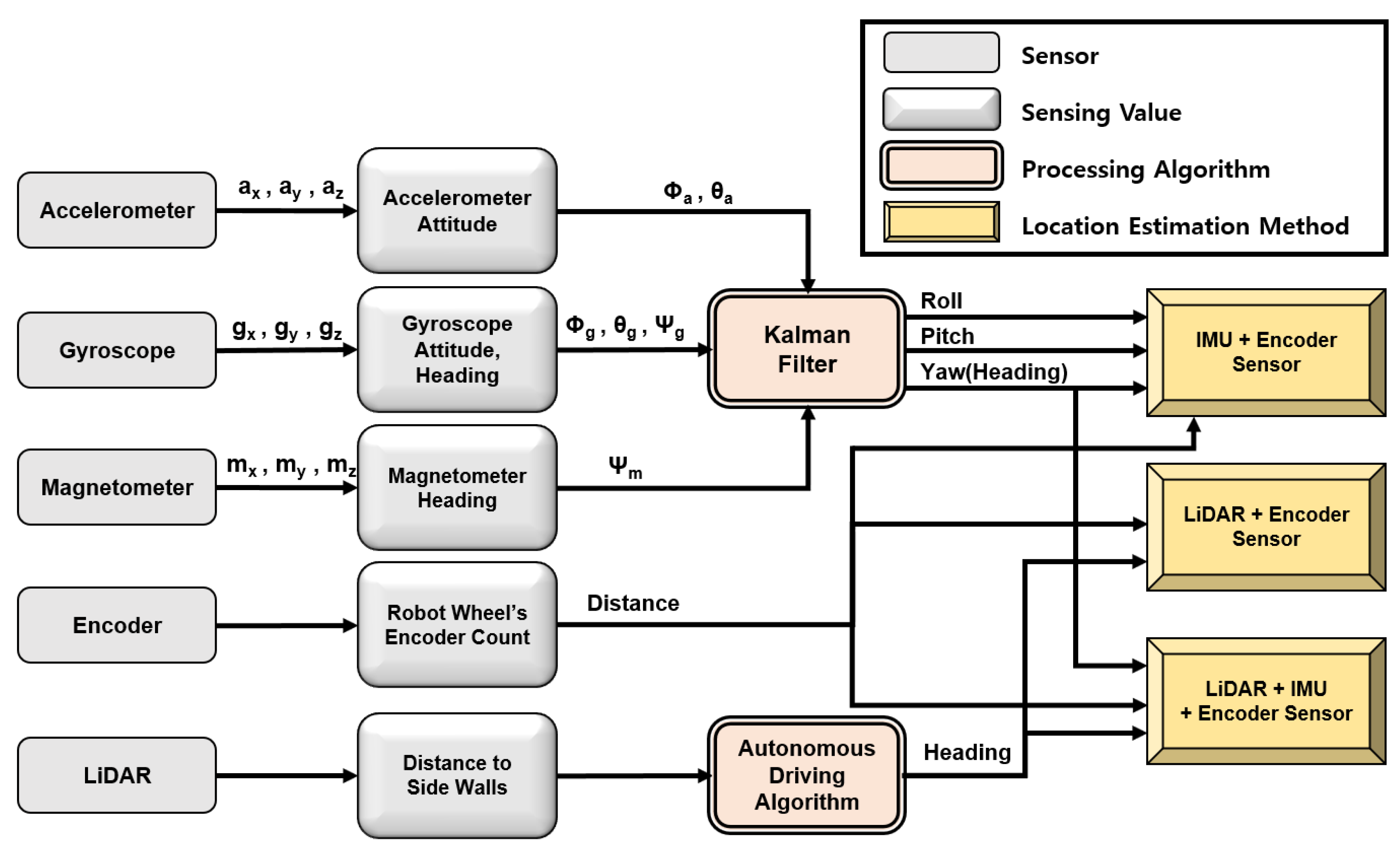
In this study, we compared the accuracy of three location estimation methods of an autonomous driving robot in an underground mine environment: inertial measurement unit with encoder (IMU + encoder) sensors, Light Detecting and Ranging with encoder (LiDAR + encoder) sensors, and IMU with LiDAR and encoder (IMU + LiDAR + encoder) sensors. The study presents the autonomous driving robot system, sensors, and location estimation methods used in the experiments. The location of the autonomous driving robot was estimated using each of the three methods as it drove through the indoor laboratory, which simulated an underground mine, and in an actual underground mine. We analyzed the accuracy of the results by comparing the estimated robot location with its actual location.
3. Indoor Experiment
In this study, an accuracy comparison experiment was conducted on the three location estimation methods in an indoor laboratory. The indoor experiment was conducted five times repeatedly at an indoor laboratory simulating an underground mining environment. The raw data measured from the IMU, LiDAR and encoder sensors, and all x, y, z coordinates and directional angles calculated in real time while the robot was driving through the indoor laboratory, were recorded. The location estimation accuracy was analyzed by comparing the recorded actual location with the estimated location.
3.1. Indoor Laboratory Simulation
Figure 5 shows the overall composition and sectional picture of the indoor laboratory used in this study. The indoor laboratory was 2.5 m wide, 2.6 m high, and 30 m long; the longitudinal direction of the robot’s front was set along the x-axis, and the transverse direction along the y-axis at the starting point. The indoor laboratory was composed of the X change, X-Y change, X-Z change, and Y change sections. The accuracy of the change in coordinates of the corresponding sections among X, Y, and Z were calculated as the robot was driving in each section. The temporary wall in the experiment was higher than the detection height (60 cm) of the LiDAR sensor in all sections, and the central point of the road was marked on the floor. To measure the accuracy of the Z value, an inclined terrain with a height of approximately 12.5 cm was set. The Bluetooth beacon was installed at the robot’s destination so that the autonomous driving robot stopped automatically.
3.2. Indoor Experiment Method
In this study, the location of the robot was estimated using the IMU + encoder, LiDAR + encoder, and IMU + LiDAR + encoder sensors, respectively. Additionally, the robot’s actual location was determined by filming the robot’s driving process. To measure the accuracy of the Z value, the Z coordinate was analyzed by comparing the shape of the actual slope structure with the robot’s X-Z coordinates. The mean absolute error (MAE) method was applied to determine the error of the location estimation methods. During the experiment, the data acquired from the sensors were set to be stored in 0.1 s, and compared with the actual robot location in 1 s.
3.3. Indoor Experimental Results
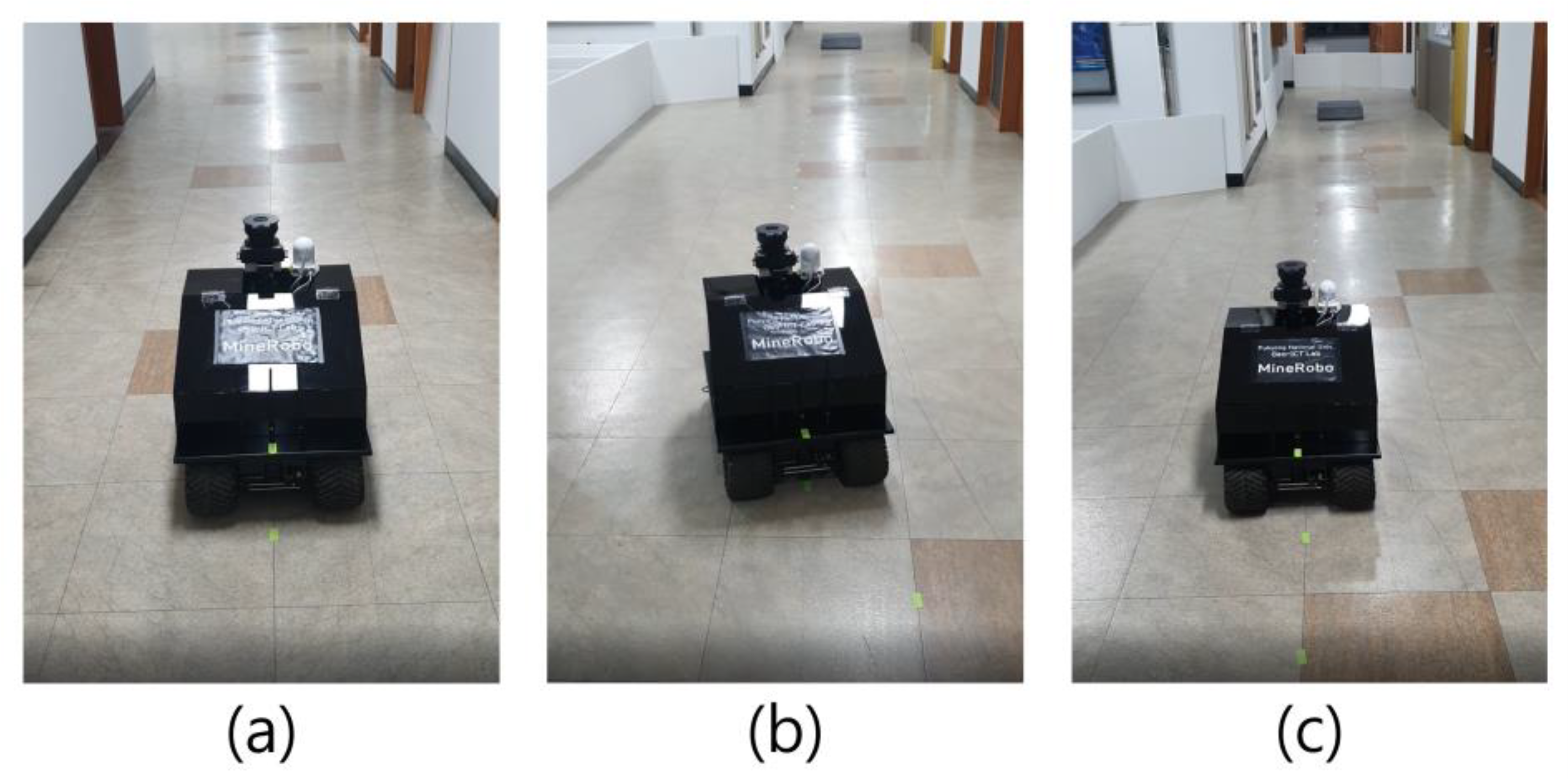
Figure 6 shows the autonomous driving robot conducting the location estimation experiment at the indoor laboratory. It was observed that the autonomous driving robot stably drove along the central line of the road in the entire experimental section; the ability to climb on a temporarily made ramp was used to measure the accuracy of the z-axis. The autonomous driving robot was driven on approximately the same path during the five repeated experiments, taking an average of 73.3 seconds to drive through the entire indoor laboratory.
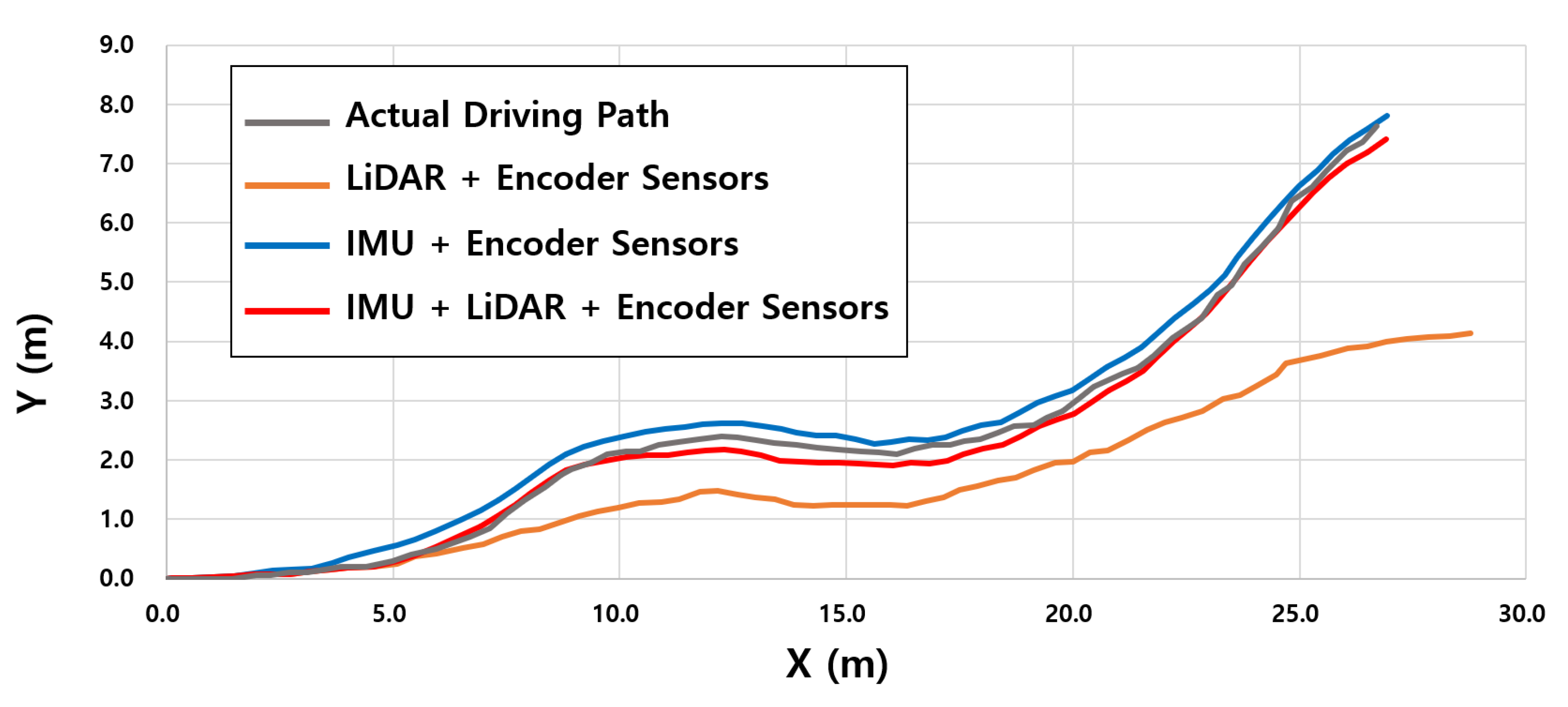
Figure 7 shows the robot’s actual driving path, and the pathways measured by the three location estimation methods. Overall, the IMU + LiDAR + encoder and IMU + encoder sensors showed similar driving paths, with the IMU + LiDAR + encoder sensors showing higher accuracy than the IMU + encoder and LiDAR + encoder sensors. The mean absolute error of the IMU + LiDAR + encoder sensors was 0.09 and 0.08 m in the X and Y directions, respectively. For the IMU + encoder sensors, the mean absolute error was 0.20 and 0.18 m in the X and Y directions, respectively. Additionally, for the LiDAR + encoder sensors, the mean absolute error was 0.90 and 0.72 m in the X and Y directions, respectively. The LiDAR + encoder sensors produced greater errors in the sections where the robot’s orientation angle changes rapidly, and the accuracy of the location estimation decreases significantly in the sections where the robot rotates vertically. However, the IMU + LiDAR + encoder and IMU + encoder methods show a flow that is similar to the actual driving path.
The encoder sensors were used to measure the distances in all methods, and the IMU and LiDAR sensors were used to measure the robot’s heading angle. Therefore, the difference in the driving path was caused by the accuracy difference between the two heading measurement sensors.
When comparing the two types of heading measurement sensors, the cumulative error was expected to be relatively large for the LiDAR sensors as there was no filter to correct the raw value. It was also expected that there would be a difference between the angle at which the robot would be set to drive along the central point of the road and the angle at which the robot would actually drive. In addition, if the robot rotates at a large angle on the road, it does not recognize the accurate angle.
Based on the results, the IMU + LiDAR + encoder sensors showed an overall higher accuracy than the IMU + encoder and LiDAR + encoder sensors. For the IMU sensors, three types of sensors (acceleration, angular velocity, and magnetic) are fused and calibrated in real time to estimate the robot’s angle and can recognize directional rotation of up to 180°. In contrast, the LiDAR sensors measure the distance to the left and right walls and estimate the heading direction according to the difference between the two. Therefore, when the distance to the left and right wall suddenly changes, the calculated heading value also tends to vary significantly. In particular, it was confirmed that the direction estimation ability is rapidly decreasing at a 90° intersection. Therefore, if the two types of heading measurement sensors were compared, the accuracy of the IMU sensor is higher than that of the LiDAR sensor, but the IMU + LiDAR + encoder sensors combined, leveraging the advantages of each of the two sensors according to the heading angle, which showed the highest accuracy overall.
Table 2 shows the location estimation methods’ mean absolute error for each section during the five experiments. The X-change section has a straight portion with a constant road width. In this straight section, the distance from the LiDAR sensor to the left and right walls is similar; therefore, the location estimation accuracy was excellent when using the high-performance LiDAR sensor. On the other hand, the IMU sensors showed relatively high errors; it was inferred that they were caused by the robot’s body vibration during driving, and the poor performance of the magnetic sensor when it was close to metallic materials. The IMU + LiDAR + encoder and LiDAR + encoder sensors showed the same results because the headings were measured in the same way through the LiDAR sensors in the X-change section.
In the X-Y change section, the IMU + LiDAR + encoder and IMU + LiDAR sensors had cumulative errors similar to the previous section, whereas the LiDAR sensor’s errors increased sharply as the road width changed and the steering shift increased. In the X-Z change section, the IMU + encoder sensors showed a similar cumulative error to the previous section; however, the LiDAR + encoder sensors had fewer cumulative errors compared to the previous sections. There was no shift in steering because the height in the Z direction changed, but the Y value did not. Therefore, it was observed that the error in that section was relatively small, similar to the first section, and since the IMU + LiDAR + encoder sensors measure heading angle using the LiDAR sensor in a straight section, errors were accumulated in a similar manner to the LiDAR + encoder sensors. Finally, in the Y-change section, the LiDAR + encoder sensors showed the largest error among all sections, whereas the IMU + encoder sensors’ accumulated errors remained constant, as in all the previous sections. The LiDAR sensor could not detect the driving direction of the robot whenever it used a large steering change to turn, hence the X and Y values showed large errors.
Overall, all location estimation methods tended to accumulate errors over time. The IMU + encoder sensors showed similar errors in each section, whereas the LiDAR sensors showed very high accuracy in the straight sections, but their location estimation accuracy decreased sharply in the sections where there was a large steering shift. The IMU + LiDAR + encoder sensor generated errors in each section corresponding to the method with the highest accuracy in that section among the two different methods, so the total accumulated error was the smallest.
Figure 8 shows the X-Z position of the autonomous driving robot measured on an inclined terrain. The length and height of the Z-axis terrain are approximately 1.7 and 0.125 m, respectively. The tilt angle of the terrain was measured by the pitch angle estimated by the IMU sensor, and the distance was measured by the encoder sensor. The mean absolute error obtained from comparing the 58 measured Z-coordinates and the actual slopes was 0.58 cm.
In
Figure 9, the lateral and longitudinal absolute error and velocity between the three types of location estimation methods (IMU + encoder, LiDAR + encoder, and IMU + LiDAR + encoder sensors) were compared. When measuring the robot’s heading angle, it was found that combining the two sensor types generated a smaller error than that of the two previously used location estimation methods. These results show a significant difference in the overall location estimation accuracy, as there was a straight road in all areas of the X-Y-change and Y-change sections, as well as some areas of the X-Z-change and Z-change sections.
In the longitudinal/lateral velocity graph from
Figure 9c,d, the IMU + LiDAR + encoder sensors showed a similar flow to the LiDAR + encoder sensors in the X-change section, and showed a similar flow to the IMU + encoder sensors in the steering change section. The LiDAR + encoder sensors showed relatively little change in lateral and longitudinal velocity compared to the other two methods. In particular, in the Y-change section, the lateral velocity should be higher than the longitudinal velocity because the robot is driven along the Y axis after rotating approximately 90°, but the LiDAR + encoder sensors drive at an almost constant speed in all sections. It is assumed that the LiDAR sensor cannot recognize that the robot is driving after it turns at a large angle. On the other hand, for the IMU sensors, the robot’s rotation can be recognized to confirm that the longitudinal speed is reduced and the lateral speed is increased.
4. Field Experiment
4.1. Field Expriment Method
In this study, a field experiment of the three location estimation methods of autonomous driving robots was conducted in underground mines. While the autonomous driving robots were driving in the underground mine tunnel, the robot’s location was estimated by each method, and the actual location was measured by filming the robot’s driving path. The mean absolute error (MAE) method was used to compare the actual location of the robot with its estimated location. While the autonomous robot was driving, the sensor data and the calculated location were stored every 0.5 s, and this was compared to the actual robot location.
4.2. Experiment Area
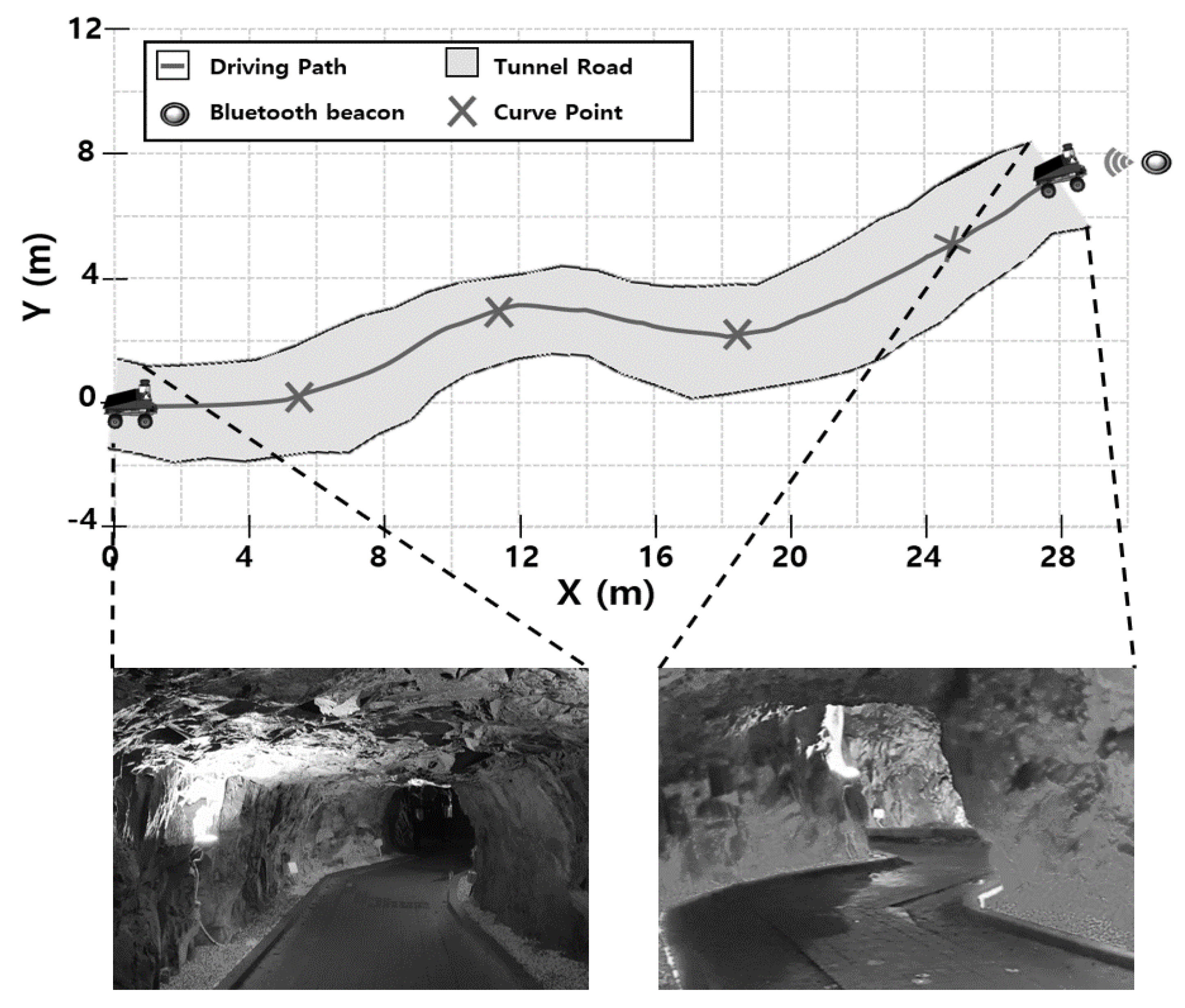
The study area was an amethyst mine (35°32′43″ N, 129°5′37″ E) in Ulju-gun, Ulsan, Korea. The mine is 2.5 km long, has an average internal temperature of 12 to 16 °C, and an area of 16,000 m
2, and is currently closed. A section of the mine, 30 m long and 3 m wide, shown in
Figure 10, was set up as the experiment area. The experiment area contains four curved points, each with a curvature of −30°, 0°, −30° and −40°, respectively, compared to the starting point. Since the wall surface of the experiment section was higher than the LiDAR’s sensing height (60 cm), it was possible to measure the distance to the left and right wall surfaces through the LiDAR sensor in all driving sections. Before conducting the experiment, a scale surveying was performed to measure the width and length of the tunnel, and sticky notes were attached to the bottom of the tunnel at regular intervals to accurately observe the location of the robot. Bluetooth beacons were installed at the destination, so that the autonomous driving robots can be automatically stopped.
4.3. Field Experiment Results
Figure 11 shows the autonomous robots driving in the underground mine during the field experiment. The autonomous driving robot received signals from the remote controller at the starting point and drove through four curved points stably cornered. The entire drive through the experiment section was performed along the central point of the mine, without touching the sidewalk blocks installed at a width of about 1 m, and the total driving time was approximately 66 s.
Figure 12 shows the actual driving path of the autonomous robots in the underground mine, and the driving path measured through the three location estimation methods. Overall, the IMU + LiDAR + encoder sensors have the highest accuracy, followed by IMU + encoder sensors and the LiDAR + encoder sensors, which is similar to the indoor experiment results.
The mean absolute error in the method using the IMU + LiDAR + encoder sensors was 0.11 m and 0.11 m in the X and Y directions, respectively (
Table 3). The IMU + LiDAR + encoder sensors show similar paths to the LiDAR + encoder sensors on the straight road, and similar paths to the IMU + encoder sensors on the curved road.
The X direction mean absolute error of the IMU + encoder sensors was 0.12 m, and the Y direction mean absolute error was 0.23 m. The IMU + encoder sensors showed a slightly higher location estimation accuracy in the field experiments compared to the indoor experiments.
The LiDAR + encoder sensors show relatively high accuracy on straight roads, similar to the indoor experiment, while errors tended to accumulate when the robot’s steering changed rapidly. The LiDAR + encoder sensors’ X direction mean absolute error was 0.52 m, and the Y direction mean absolute error was 0.91 m, showing relatively high accuracy compared to the indoor experiments. In the indoor laboratory, there was a section where the width changed rapidly or was bent vertically, whereas, in the underground mines, the width of the road gradually increased and decreased, so the robot’s heading did not change rapidly. Additionally, the LiDAR + encoder sensors did not recognize, in the indoor experiment, the large rotation of the robot’s steering, so a large error occurred. In the field experiments, however, the robot’s steering did not change rapidly because the tunnel road width increased and decreased gradually.
In order to quantitatively compare the accuracy of the location estimation according to the steering change, the boundary between the straight and curved sections was clearly set, and the width and curvature of the road were changed significantly. However, since the underground mine tended to change gradually, in the form of shafts or road curvatures, the accuracy of the location estimation was generally increased. In particular, in the case of the LiDAR sensor, the positioning performance was very low because the sensors did not recognize the robot’s large angle rotation in the indoor laboratory; however, in the underground mine environment, the robot’s headings changed frequently at small angles, meaning that the accuracy of the location estimation could have increased slightly. Unlike the indoor laboratory, the actual underground mine environment is large and most of the roads are almost straight. Therefore, the importance of the LiDAR sensors, which showed high accuracy when the robot moved in a straight direction, was expected to increase further.
5. Conclusions
In this study, an accuracy comparison experiment was conducted for three location estimation methods of an autonomous driving robot (IMU + encoder, LiDAR + encoder, and IMU + LiDAR + encoder sensors) in an indoor laboratory that simulated an underground mine, and an actual underground mine. The robot location was estimated by each of the three methods as the autonomous vehicle was driving through the indoor laboratory, in a total of five repetitive experiments, and through an underground mine. The results accuracy was analyzed by comparing the estimated with the actual robot location. From the results, the IMU + LiDAR + encoder sensors generally showed the highest accuracy, followed by the IMU + encoder sensors and the LiDAR + encoder sensors. When the entire test site was divided into sections, the IMU + encoder sensors showed high performance on the curved roads, whereas the LiDAR + encoder sensors showed high performance on the straight roads. The IMU sensor showed a constant error in all the sections owing to the robot’s vibration, whereas the LiDAR sensor showed relatively high accuracy in the straight sections with a constant distance to the wall. Since the IMU + LiDAR + encoder sensors were used by switching between the two types of heading measurement sensors, an error occurred corresponding to the method with the relative highest accuracy among the two different methods in each section. As a result, the IMU + LiDAR + encoder sensors method, which uses two types of heading measurement sensors together based on the steering angle, showed the highest overall accuracy in all sections.
A correction filter that could improve the localization accuracy of the robot was not applied in this study; in the future, if localization correction algorithms such as the Kalman and particle filters are applied, the accuracy of the location estimation will be further improved. It will also be possible to improve the localization accuracy by utilizing pre-built LiDAR maps and point clouds measured by the LiDAR sensors. Additionally, if a wide range of environmental sensors such as vision cameras are used, it will be possible to check the overall road condition, and correct the position of the robot by grasping the structural shape. The autonomous robot used in this study drove at the same speed on all paths. However, in the future, additional experiments should be conducted to compare changes in the location estimation accuracy based on different robot speeds.
If autonomous robots are used in underground mining environments, they can explore areas that are difficult for humans to access, and productivity can be improved by automating the equipment used in the underground mines through autonomous driving technology. Additionally, the location estimation technology can be combined with environmental sensors to automate the overall environmental monitoring of tunnels. Location estimation technology is the basis for the work of exploring underground mines, such as tunnel mapping, environmental mapping, and optimal route planning. It is expected that the results of this study will be useful reference materials for the use of autonomous driving robots in underground mine environments.


