Nanosecond Laser Ablation of Ti–6Al–4V under Different Temperature
by
 ,
,
Jiantao Zhao
1,2, 
Zhenge Zhu
1,2,
Yacheng Xu
1,2,
Xueyong Song
1,2,
Yufan Wang
1,2,
Hao Peng
1,2,
Ying Wang
1,2,
Jinrong Zuo
1,2,
Xuedao Shu
1,2 and 
Anmin Yin
1,2,* 1
School of Mechanical Engineering and Mechanics, Ningbo University, Ningbo 315211, China
2
Zhejiang Key Laboratory of Part Rolling Technology, Ningbo University, Ningbo 315211, China
*
Author to whom correspondence should be addressed.
Appl. Sci. 2020, 10(13), 4657; https://doi.org/10.3390/app10134657
Submission received: 25 May 2020
/
Revised: 29 June 2020
/
Accepted: 1 July 2020
/
Published: 6 July 2020
(This article belongs to the Special Issue Laser Material Manufacturing)
Abstract
:Multi-pulse nanosecond laser ablation of Ti–6Al–4V is a complex process. In this study, the effect of substrate temperature on the nanosecond laser ablation of Ti–6Al–4V was investigated. Morphology, diameter and depth of ablation craters were observed; ablation efficiency ω (μm3/mJ) was proposed to analyzes the ablation process. The results showed that, with the increasing of substrate temperature, the ablation craters’ diameter increased and depth decreased, while ω initially increased, but then decreased rapidly. Furthermore, with increasing pulse number, the depth of ablation crater increased linearly, while the growth of the diameter gradually slowed down and tended to be stable after the 16th irradiation. The above changes were different in details at different substrate temperatures.
1. Introduction
Ultra-short lasers are widely used in laser etching [1], laser drilling [2,3] and pulsed laser deposition (PLD) [4].
After decades of experimental research, people have a clear understanding of the ablation process of metal materials ablated by nanosecond laser pulses [5,6,7]: When a laser pulse acts on the surface of metal target, the main form of material ablation is normal evaporation in the lower laser fluence. In this case, laser pulse causes the material to melt and boil, forming a liquefaction crater. The material is removed directly by evaporation from the liquefaction crater. With increasing laser fluence, the temperature of ablated area on the target surface increases continuously. When the temperature reaches—or even exceeds—the threshold, phase explosion and explosion-boiling instead of normal evaporation become the main factors affecting ablation, which are mainly manifested by explosive spattering of melt and molten droplets. In addition, the plasma-shielding effect should be taken into account when the laser fluence is high. Because of the plasma-shielding effect, the absorption rate of the target to the laser will decrease significantly [8].
There have been many reports on nanosecond (femtosecond) laser ablation of metal. Porneala, C [9] gave the characteristics of nanosecond laser ablation of aluminum experimentally—and many studies investigated ablation process both experimentally and numerically [10,11,12], two-temperature model has been widely used in numeric studies. The effect of medium and phase explosion on the nanosecond laser ablation of aluminum is discussed in Cao, Y. F’s study [13]. The influence of laser-pulse wavelength, base material and medium were studied in [14,15,16].
However, most research has focused on PLD and laser etching. Few have focused on laser ultrasonic testing. Aiming to study its ablation characteristics and provide reference for the selection of laser pulse in laser ultrasonic testing, we selected the laser pulse parameters commonly used in laser ultrasonic testing to carry out multi-pulse ablation experiments. In addition, the laser energy selected in our experiment was very high, and the laser fluence was far beyond the threshold value.
Titanium alloy—as a kind of material with high strength, corrosion resistance and high temperature resistance—has been widely used in the fields of biologic materials [17], aerospace [18], marine engineering [19]. Of all titanium alloys, Ti–6Al–4V titanium alloy is the most widely used; a number of titanium alloys are improved based on Ti–6Al–4V [20]. Laser ultrasonic testing is an effective way to detect titanium alloy [21]. Therefore, the study of nanosecond laser ablation characteristics of Ti–6Al–4V titanium alloys has a certain reference value for the laser ultrasonic testing of titanium alloys.
In this investigation, two groups of experiments were carried out. Experiment A aimed to study the effect of substrate temperature on Ti–6Al–4V multi-pulse nanosecond laser ablation process generally, In Experiment B, the universality of the phenomenon of Experiment A under different laser fluence and pulse number was further studied, and the relationship among pulse number, substrate temperature and ablation characteristics was also studied.
Based on the observation of Ti–6Al–4V multi-pulse nanosecond laser ablation characteristics, the relationship between substrate temperature and ablation characteristics was studied. Ablation efficiency ω was proposed to analysis the ablation process. The phase explosion model and energy accumulation effect were considered to explain the experimental phenomena.
2. Experimental Materials and Methods
The materials used in this study were Ti–6Al–4V. All samples were selected from the same base metal. The size of the samples were all 100 mm × 10 mm × 2 mm. The samples were carefully polished before ablation. Its chemical element composition is shown in Table 1.
In order to obtain the different situations of ablation craters, this study was divided into two groups of experiments:
Experiment A: experiment of low pulsed laser fluence ablation at different temperature. The experiment was divided into 8 groups at different substrate temperatures of 50 °C, 100 °C, 150 °C, 200 °C, 250 °C, 300 °C, 350 °C and 400 °C, each group took 1 Ti–6Al–4V slice to performed irradiation of 50 pulses.
Experiment B: Experiment of high pulsed laser fluence ablation at different temperature. The experiment was divided into 8 groups at different substrate temperatures of 50 °C, 100 °C, 150 °C, 200 °C, 250 °C, 300 °C, 350 °C and 400 °C. Each group took 6 Ti–6Al–4V samples and performed irradiation of 2n (n = 0, 1, 2, 3, 4, 5) pulses on samples separately.
The nanosecond laser used for the ablation experiment was the Q-switch neodymium: yttrium–aluminum–garnet laser. The laser parameters of each experiment is shown in Table 2. The laser pulses were applied on the sample surface after focusing. Different laser energies and pulse numbers were obtained by changing the parameters of the laser equipment. A heater was used to heat the Ti–6Al–4V slice, sample (Ti–6Al–4V slice) and heater were placed on a mobile platform, which allowed the user to adjust the position of the sample. The schematic diagram of the experimental device is shown in Figure 1. We obtained the required spot size by focusing on the upper surface of the target. However, limited by focusing accuracy, the focus was actually below the upper surface.
We estimated the spot diameter after focusing by measuring the diameter of the splash area produced by a single pulse, as shown in Figure 2. The splashing area diameter of two samples was measured, and the average value was taken as the spot diameter after focusing.
After ablation, samples were fully cooled, the optical microscope image and data of ablation craters were obtained by a digital microscope HIROX KH-8700, and the scanning electron microscope images were obtained by a field emission scanning electron microscope (FESEM) HITACHI SU5000.
3. Results and Analysis
3.1. Ablation Analysis of Experiment A
Figure 3 presents the top-view optical microscope images of ablation craters under substrate temperature of 50 °C–400 °C, after irradiation of 50 pulses.
It can be seen from figures that the morphology of the ablation craters changed little under different substrate temperatures (50–400 °C), and there were heat-affected zones with different color and small craters near the ablation crater.
In order to observe the ablation crater more clearly, the top-view scanning electron microscope images of ablation craters are shown in Figure 4. From the ablation craters figure of SEM images, it can be seen that the ablation craters present a stepped shape, the craters’ diameter of the outermost ring was the largest and the craters’ diameter was reduced in a downward circle; with the increase of substrate temperature, the diameter of the outermost ring of the ablation craters also gradually grew larger, and the splashing structure of the ablation slag also increased.
We explain this phenomenon in this way: In this experiment, focused laser was used and applied on the target upper surface. However, because limited by focusing accuracy, the focus was actually below the upper surface. After each pulse, the ablation depth increased, and the distance between the ablation plane (spot) and the focal plane (focus) decreased. Therefore, the spot size (ablation radius) decreased step-by-step with the increasing of pulse number—resulting in the above phenomenon of ablation craters’ stepped shape.
Figure 5b illustrates the relationship between ablation-crater diameter and substrate temperature.
It was found that the diameter of the ablation crater increase as substrate temperature increased. Moreover, the diameter increased fastest in the middle and slowest at both ends, and the fitting curve was similar to Gaussian distribution curve.
Energy accumulation effect is used for explaining the multi-pulse ablation of metals in existing researches [11,22,23]. Since laser pulse energy was accumulated in the form of heat, substrate temperature could be considered as the initial accumulative energy. As the substrate temperature increased, less energy was absorbed from heating to ablation, and the ablation threshold Ith decreased.
The relationship between laser fluence (energy density) and cross section radius is [23]:
where r is the distance (μm) to the center of the beam, Imax is the peak-on-axis fluence (J/μm2) of the laser beam, and ω is the beam waist radius (μm). Let I(r) be equal to the ablation threshold Ith, the ablation diameter d is:
Since Ith decreased with the increasing of substrate temperature, the diameter of the ablation crater was positive to the substrate temperature, while the Gaussian distribution of the curve may be due to phase explosion and plasma shielding: The rapid growth of radius between 150–250 °C may be due to the stronger phase explosion, while the slow growth of radius after 300 °C may be due to the stronger plasma shielding effict.
Figure 6 presents the relationship between ablation depth (after irradiation of 50 pulses) and substrate temperature. As the substrate temperature increased, the ablation depth showed a downward trend. In details, when the substrate temperatures were 50 °C and 100 °C, the ablation depths were approximately the same. When the substrate temperature rose above 100 °C, the ablation depth started to decrease, and a rapid decrease appeared between 350 °C and 400 °C.
We use cone to approximate the shape of the ablation crater, so the volume of the ablation crater can be estimated as:
where V is the volume of ablation crater, in unit of μm3; h is the ablation depth, in unit of μm; D is the diameter of ablation crater, in unit of μm.
Thus, we can get ablation efficiency ω, in unit of μm3/mJ:
where n is pulse number.
Figure 7 presents the relationship between ω and substrate temperature. It was found that between 50 °C and 200 °C, the slope of the curve increased with the increase of substrate temperature. When the temperature reaches 250 °C, the slope decreased greatly; when reaches 400 °C, the slope decreased to a negative value, and the ablation efficiency ω obviously decreased. On the whole, it showed a trend of rising first, and then declining.
We use the following theory to explain the above phenomena:
The phase-explosion effect: When the target’s temperature is extremely high due to laser irradiation, phase explosion instead of normal evaporation become the main coefficient affecting ablation, explosion boiling will happen and mainly manifested by explosive spattering of melt and molten droplets. Existing research has confirmed that the occurrence of phase explosion will greatly accelerate the removal of materials [5,6,10,11,13].
The plasma-shielding effect: The influence of plasma was investigated in many studies; the formation of plasma will decrease the absorption rate of laser [8]. In addition, Zhao, X.Y. took plasma shield effect into consider to correct the energy distribution of the incident laser and found that the increment of laser fluence leads to a slower nonlinear increment in diameter of melt zone [12]. Vadillo, J.M. pointed out in his study that at high laser fluence, plasma shielding will efficiently attenuates the incoming Laser radiation and reduces the ablation rate [24].
We think that the substrate temperature can be considered as the initial accumulative energy, and it can be further equivalent to laser fluence. Thus, high substrate temperature may strengthen phase explosion, as well as cause plasma-shielding effect to occur in advance. Because of the inverted cone shape of the ablation pit and the Gaussian distribution of the laser pulse energy, the plasma is easier to gather at the ablation center and less likely to form or thinner at the ablation edge. Therefore, the earlier the plasma formed, the more ablation depth will be reduced, and the final ablation depth will be shallower, but the radius of ablation pit will not be affected, finally result in the phenomenon in Figure 5 and Figure 6. Phase explosion effect and the plasma-shielding effect can also explain the phenomenon showed in Figure 7, ω increase rapidly between substrate temperature of 150 °C and 200 °C indicated that phase explosion may occurred, while the decrease between 350 °C and 400 °C may indicated that a strong plasma shielding occurred. Further studies will be described in Experiment B.
3.2. Ablation Analysis of Experiment B
We observed and compared the ablation crater morphology of 1–32 pulses irradiation at different substrate temperatures, taking 50 °C as example, shown in Figure 8. The corresponding data are shown in Table 3.
From Figure 8, it was found that at substrate temperature of 50 °C, after the first pulse irradiation, obvious ablation crater was not formed. After the 4th pulse irradiation, an obvious ablation crater was formed on the surface of targets, and ablation depth increase rapidly between pulse number of 4 and 32.
In particular, the morphology of the ablation craters after the 4th pulse irradiation at different substrate temperature are compared and shown in Figure 9. It was found that after the 4th pulse irradiation, obvious ablation craters were formed in 50 °C group, however, with the increasing of substrate temperature, the ablation craters gradually became inapparent, in 400 °C group, there was only a shallow crater.
In addition, we compared the ablation craters’ cross section after irradiation of 32 pulses at different substrate temperatures, as shown in Figure 10. It was found that the morphology of the ablation craters were more slender in a lower substrate temperature.
Figure 11 presents the relationship between ablation crater’s diameter and pulse number. It was found that when the pulse number are less and the ablation craters are not obvious, the ablation craters’ diameter increases rapidly with the increasing of pulse number, when the pulse number are more and the ablation craters are obvious, the ablation craters’ diameter is almost invariant.
We took the diameter of the ablation crater after irradiation of 32 pulses, and drew the Diameter-Substrate temperature curve, as shown in Figure 12. Similar to Figure 5b of experiment A, the diameter of the ablation crater increased as substrate temperature increased, and the fitting curve is similar to Gaussian distribution curve.
Figure 13 presents the ablation depth–pulse number curves at substrate temperatures of 50 °C–400 °C. It was found that after the 4th ablation, the curve became straight. The results show that at the same temperature, the ablation of laser pulses after the 4th pulse irradiation was similar with each other. In addition, as the substrate temperature increased, the slope of the curves showed a downward trend.
In details, between the 1st pulse irradiation and 8th pulse irradiation, the slope of the curve was stable first and then rising, the rising point of 50 °C–200 °C was forward, and 250 °C–400 °C was backward. It shows that the ablation may have been greatly affected by the plasma-shielding effect when the substrate temperature was more than or equal to 250 °C. In combination with the phenomena shown in Figure 9, we think that this indicates that a phase explosion occurs at this pulse number (4 pulsed). Therefore, it could be roughly estimated that under the laser parameters of this experiment, the ablation threshold corresponding to 200 °C and pulse number 4 was 0.7143 μJ/μm2, that was 71.430 J/cm2. This can be used as a useful reference.
In Figure 14, we change the horizontal axis to the substrate temperature (°C), compare the relationship between the ablation depth and the substrate temperature under certain pulse number. It was found that after the first and second pulse irradiation, the ablation depth is very small and almost unchanged with the increase of substrate temperature. When the pulse number increase to 4, as the substrate temperature rises, the ablation depth declines, and the more the pulse number, the more obvious the decline is.
Combined with Figure 13 and Figure 14, we speculate that the reason for the decrease of the ablation crater’s depth is that the increase of the substrate temperature will advance and strengthen the plasma-shielding effect. Plasma may have appeared after the second pulse irradiation at high substrate temperature, which will affect the further absorption of laser energy and inhibit the generation of violent explosion boiling (phase explosion), resulting in slow growth of ablation rate, and finally, the ablation depth at high substrate temperature will not increase, but decrease.
Based on the above data, we calculated the ablation efficiency ω at each substrate temperature and show them in Figure 15. It was found that when the number of pulse is less, the growth rate of ω is faster and then the growth rate of ω tends to be stable. While at high substrate temperature (250–400 °C), the turning point towards stability will be backward.
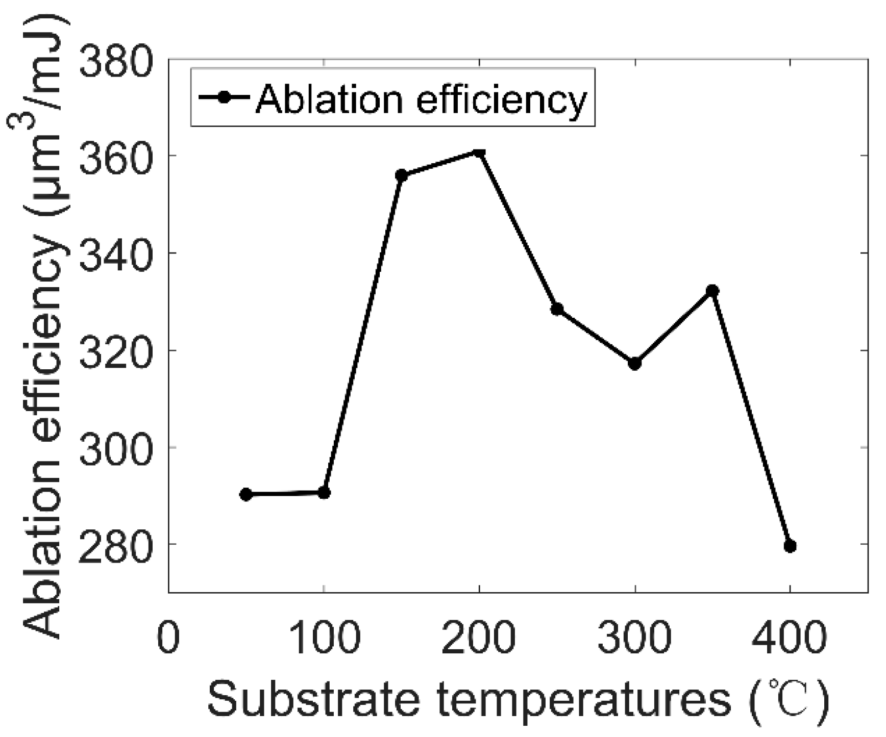
Figure 16 presents the relationship between substrate temperature and ablation efficiency ω, which is calculated by the depth and diameter of the ablation crater after 32 pulses irradiation at each temperature.
On the whole, it shows a trend of rising first and then declining, which is similar to experiment A. While ω rise rapidly when substrate temperature higher than 100 °C, which is more advanced than low laser fluence. The decrease of ablation efficiency ω may also be related to the occurrence and enhancement of plasma-shielding effect.
4. Conclusions
In this study, the influence of substrate temperature on the characteristics of Ti–6Al–4V nanosecond laser ablation is studied and the ablation efficiency ω is proposed to characterize the ablation rate, conclusions are as follows:
- In both experiments (1. laser fluence 0.1429 μJ/μm2, 50 pulses; 2. laser fluence 0.7143 μJ/μm2, 32 pulsed), with the increasing of substrate temperature, the ablation craters’ diameter increased and showed a Gaussian distribution. In addition, at pulsed laser fluence of 0.7143 μJ/μm2, with the increase of pulse number, diameter increased rapidly first and then slowed down; its final diameter was larger than the diameter at laser fluence of 0.1429 μJ/μm2;
- In both experiments, with the increasing of substrate temperature, the ablation-crater depth decreased. In addition, at pulsed-laser fluence of 0.7143 μJ/μm2, with the increase of pulse number, depth change was close to linear growth the higher the substrate temperature was, the slower the deep ablation was and its final depth was lower than the depth at pulsed laser fluence of 0.1429 μJ/μm2.
- In both experiments, with the increasing of substrate temperature, ablation efficiency ω showed a trend of rising first and then declining. In addition, at pulsed-laser fluence of 0.1429 μJ/μm2, ω rise rapidly when substrate temperature higher than 150 °C and decline rapidly at 350 °C; At pulsed laser fluence of 0.7143 μJ/μm2, ω rise rapidly when substrate temperature higher than 100 °C and declined rapidly at 350 °C. ω could approximately presented the volume ablation per unit laser energy and could be consistent with the existing theories.
Author Contributions
Experimental investigations, J.Z. (Jiantao Zhao), Z.Z., Y.X., X.S. (Xueyong Song), Y.W. (Yufan Wang) and H.P.; writing and original draft preparation, J.Z. (Jiantao Zhao), and A.Y.; writing, review and editing, Y.W. (Ying Wang) and J.Z. (Jinrong Zuo); supervision, A.Y. and X.S. (Xuedao Shu).
Funding
This research was funded by National Natural Science Foundation of China (NSFC) (51805279); Natural Science Foundation of Zhejiang Province (LY19E050001, LQ19E010003).
Conflicts of Interest
The authors declare no conflicts of interest.
References
- Böhme, R.; Pissadakis, S.; Ruthe, D.; Zimmer, K. Laser backside etching of fused silica with ultra-short pulses. Appl. Phys. A 2006, 85, 75–78. [Google Scholar] [CrossRef]
- Weck, A.; Crawford, T.; Wilkinson, D.; Haugen, H.K.; Preston, J.S. Laser drilling of high aspect ratio holes in copper with femtosecond, picosecond and nanosecond pulses. Appl. Phys. A 2008, 90, 537–543. [Google Scholar] [CrossRef]
- Manninen, M.; Hirvimäki, M.; Matilainen, V.-P.; Salminen, A. Comparison of Laser-Engraved Hole Properties between Cold-Rolled and Laser Additive Manufactured Stainless Steel Sheets. Appl. Sci. 2017, 7, 913. [Google Scholar] [CrossRef] [Green Version]
- Abdellaoui, N.; Pillonnet, A.; Berndt, J.; Boulmer-Leborgne, C.; Kovacevic, E.; Moine, B.; Penuelas, J.; Pereira, A. Growth process of nanosized aluminum thin films by pulsed laser deposition for fluorescence enhancement. Nanotechnology 2015, 26, 11. [Google Scholar] [CrossRef]
- Bulgakova, N.; Bulgakov, A. Pulsed laser ablation of solids: Transition from normal vaporization to phase explosion. Appl. Phys. A 2001, 3, 199–208. [Google Scholar] [CrossRef]
- Fishburn, J.M.; Withford, M.J.; Coutts, D.W.; Piper, J.A. Study of the fluence dependent interplay between laser induced material removal mechanisms in metals: Vaporization, melt displacement and melt ejection. Appl. Surf. Sci. 2006, 252, 5182–5188. [Google Scholar] [CrossRef]
- Chichkov, B.N.; Momma, C.; Nolte, S.; Von Alvensleben, F.; Tünnermann, A. Femtosecond, picosecond and nanosecond laser ablation of solids. Appl. Phys. A 1996, 63, 109–115. [Google Scholar] [CrossRef]
- Martynenko, Y.V. Metal droplet erosion and shielding plasma layer under plasma flows typical of transient processes in tokamaks. Plasma Phys. Rep. 2017, 43, 324–329. [Google Scholar] [CrossRef]
- Porneala, C.; Willis, D.A. Observation of nanosecond laser-induced phase explosion in aluminum. Appl. Phys. Lett. 2006, 89, 211121. [Google Scholar] [CrossRef]
- Gragossian, A.; Tavassoli, S.H.; Shokri, B. Laser ablation of aluminum from normal evaporation to phase explosion. J. Appl. Phys. 2009, 105, 103304. [Google Scholar] [CrossRef]
- Abdelmalek, A.; Bedrane, Z.; Amara, E.-H.; Sotillo, B.; Bharadwaj, V.; Ramponi, R.; Eaton, S.M. Ablation of Copper Metal Films by Femtosecond Laser Multipulse Irradiation. Appl. Sci. 2018, 8, 1826. [Google Scholar] [CrossRef] [Green Version]
- Yan, Z.X.; Mei, X.S.; Wang, W.J.; Pan, A.F.; Lin, Q.Y.; Huang, C.C. Numerical simulation on nanosecond laser ablation of titanium considering plasma shield and evaporation-affected surface thermocapillary convection. Opt. Commun. 2019, 453, 124384. [Google Scholar] [CrossRef]
- Cao, Y.F.; Zhao, X.; Shin, Y.C. Analysis of nanosecond laser ablation of aluminum with and without phase explosion in air and water. J. Laser Appl. 2013, 25, 032002. [Google Scholar] [CrossRef]
- Elsied, A.M.; Dieffenbach, P.C.; Diwakar, P.K.; Hassanein, A. Nanosecond laser-metal ablation at different ambient conditions. Spectrochim. Acta B 2018, 143, 26–31. [Google Scholar] [CrossRef]
- Kononenko, T.V.; Garnov, S.V.; Klimentov, S.M.; Konov, V.I.; Loubnin, E.N.; Dausinger, F.; Raiber, A.; Taut, C. Laser ablation of metals and ceramics in picosecond-nanosecond pulsewidth in the presence of different ambient atmospheres. Appl. Surf. Sci. 1997, 109–110, 48–51. [Google Scholar] [CrossRef]
- Benavides, O.; May, L.D.; Mejia, E.B.; Hernandez, J.A.R.; Gil, A.F. Laser wavelength effect on nanosecond laser light reflection in ablation of metals. Laser Phys. 2016, 26, 12. [Google Scholar] [CrossRef]
- Geetha, M.; Singh, A.K.; Asokamani, R.; Gogia, A.K. Ti based biomaterials, the ultimate choice for orthopaedic implants—A review. Prog. Mater. Sci. 2009, 54, 397–425. [Google Scholar] [CrossRef]
- Boyer, R.R. An overview on the use of titanium in the aerospace industry Mat. Sci. Eng. A 1996, 213, 103–114. [Google Scholar] [CrossRef]
- Gurrappa, I. Characterization of titanium alloy Ti-6Al-4V for chemical, marine and industrial applications. Mater. Charact. 2003, 51, 131–139. [Google Scholar] [CrossRef]
- Naka, S. Advanced titanium-based alloys. Curr. Opin. Solid State Mater. Sci. 1996, 1, 333–339. [Google Scholar] [CrossRef]
- Yu, J.; Zhang, D.Q.; Li, H.; Song, C.H.; Zhou, X.; Shen, S.N.; Zhang, G.Q.; Yang, Y.Q.; Wang, H.Z. Detection of Internal Holes in Additive Manufactured Ti-6Al-4V Part Using Laser Ultrasonic Testing. Appl. Sci. 2020, 10, 365. [Google Scholar] [CrossRef] [Green Version]
- Wang, W.J.; Mei, X.S.; Jiang, G.D.; Lei, S.T.; Yang, C.J. Effect of two typical focus positions on microstructure shape and morphology in femtosecond laser multi-pulse ablation of metals. Appl. Surf. Sci. 2008, 255, 2303–2311. [Google Scholar] [CrossRef]
- Li, F.; Chen, X.G.; Lin, W.H.; Pan, H.; Jin, X.; Hua, X.M. Nanosecond laser ablation of Al-Si coating on boron steel. Surf. Coat. Technol. 2017, 319, 129–135. [Google Scholar] [CrossRef]
- Vadillo, J.M.; Fernández Romero, J.M.; Rodriguez, C.; Laserna, J.J. Effect of plasma shielding on laser ablation rate of pure metals at reduced pressure. Surf. Interface Anal. 1999, 27, 1009–1015. [Google Scholar] [CrossRef]
Figure 1.
Schematic diagram of the ablation experiment.
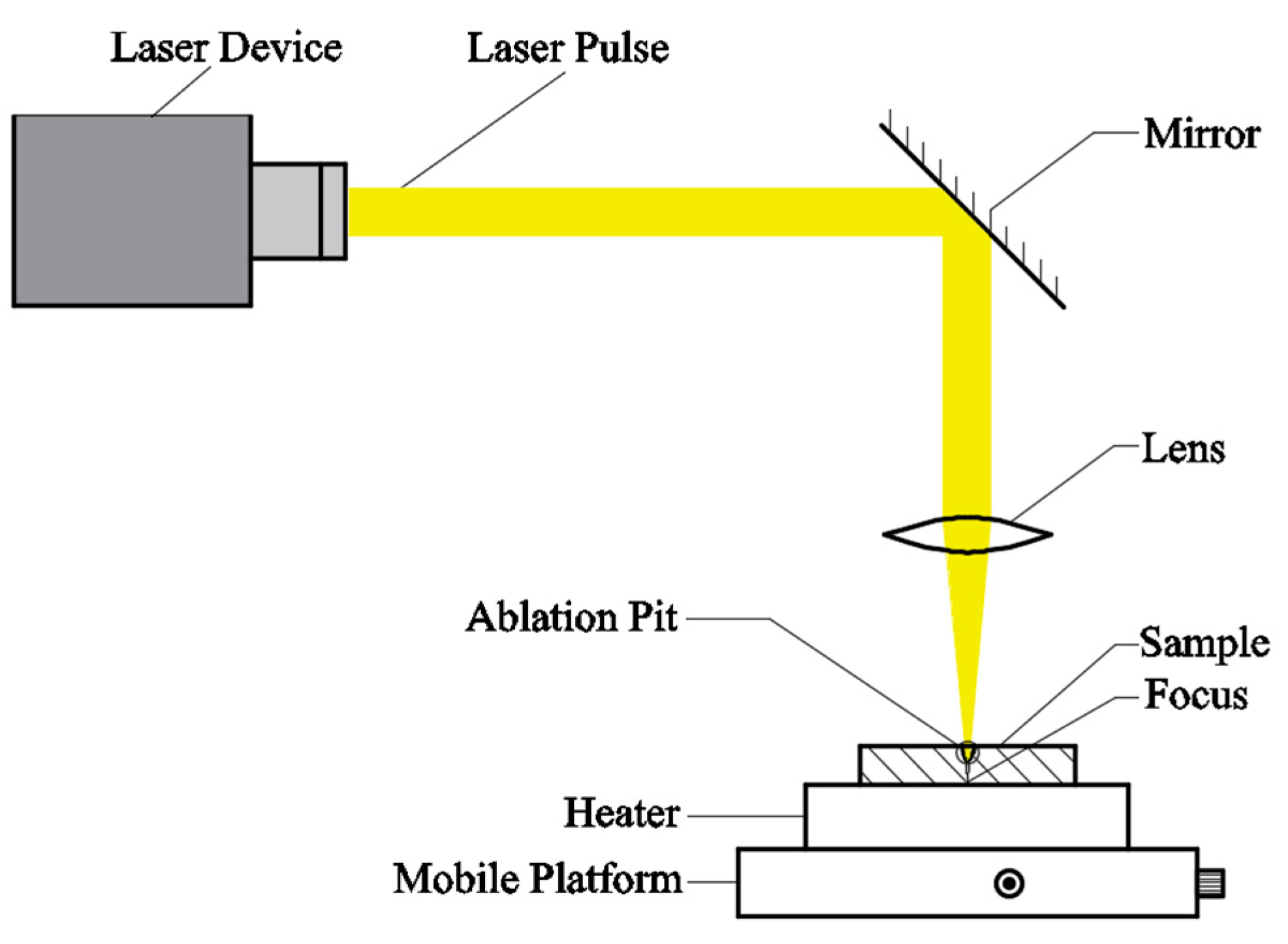
Figure 2.
Diameter of the splash area were used to estimate the diameter of laser spot.
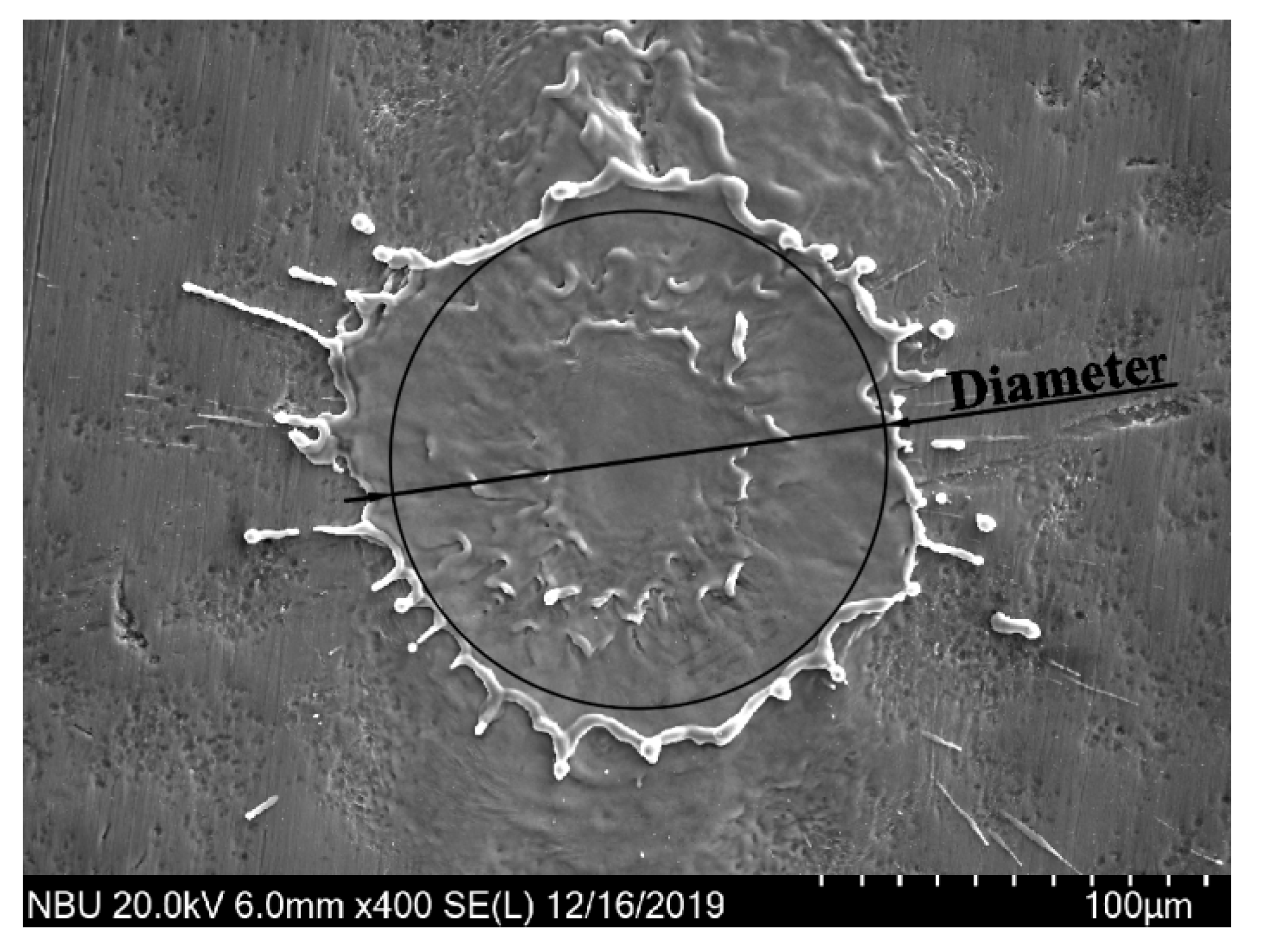
Figure 3.
Top-view optical microscope images of ablation craters. (a) 50 °C; (b) 100 °C; (c) 150 °C; (d) 200 °C; (e) 250 °C; (f) 300 °C; (g) 350 °C; (h) 400 °C.
Figure 3.
Top-view optical microscope images of ablation craters. (a) 50 °C; (b) 100 °C; (c) 150 °C; (d) 200 °C; (e) 250 °C; (f) 300 °C; (g) 350 °C; (h) 400 °C.

Figure 4.
Top-view scanning electron microscope images of ablation craters. (a) 50 °C; (b) 100 °C; (c) 150 °C; (d) 200 °C; (e) 250 °C; (f) 300 °C; (g) 350 °C; (h) 400 °C.
Figure 4.
Top-view scanning electron microscope images of ablation craters. (a) 50 °C; (b) 100 °C; (c) 150 °C; (d) 200 °C; (e) 250 °C; (f) 300 °C; (g) 350 °C; (h) 400 °C.
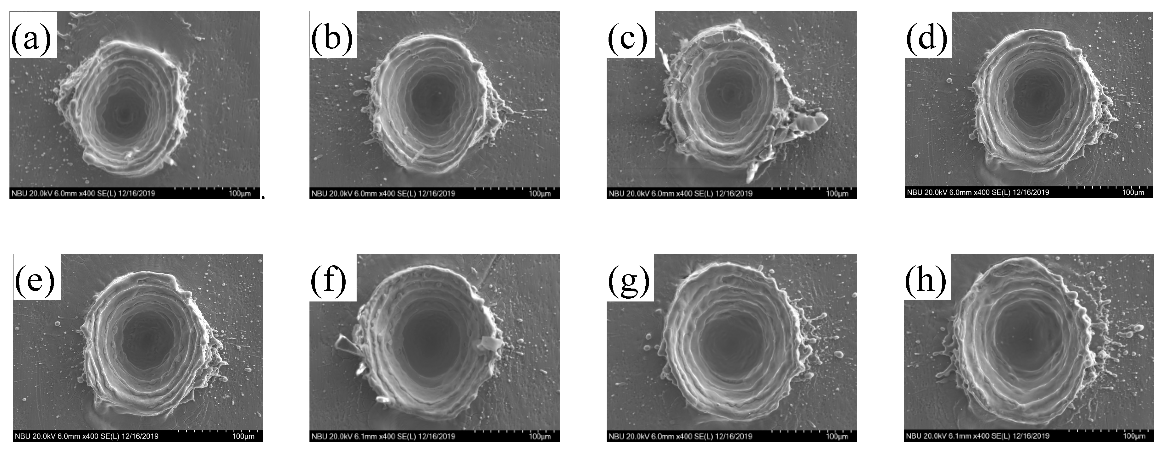
Figure 5.
(a). How we measured diameter of ablation craters; (b) diameter of ablation craters under different substrate temperature.
Figure 5.
(a). How we measured diameter of ablation craters; (b) diameter of ablation craters under different substrate temperature.
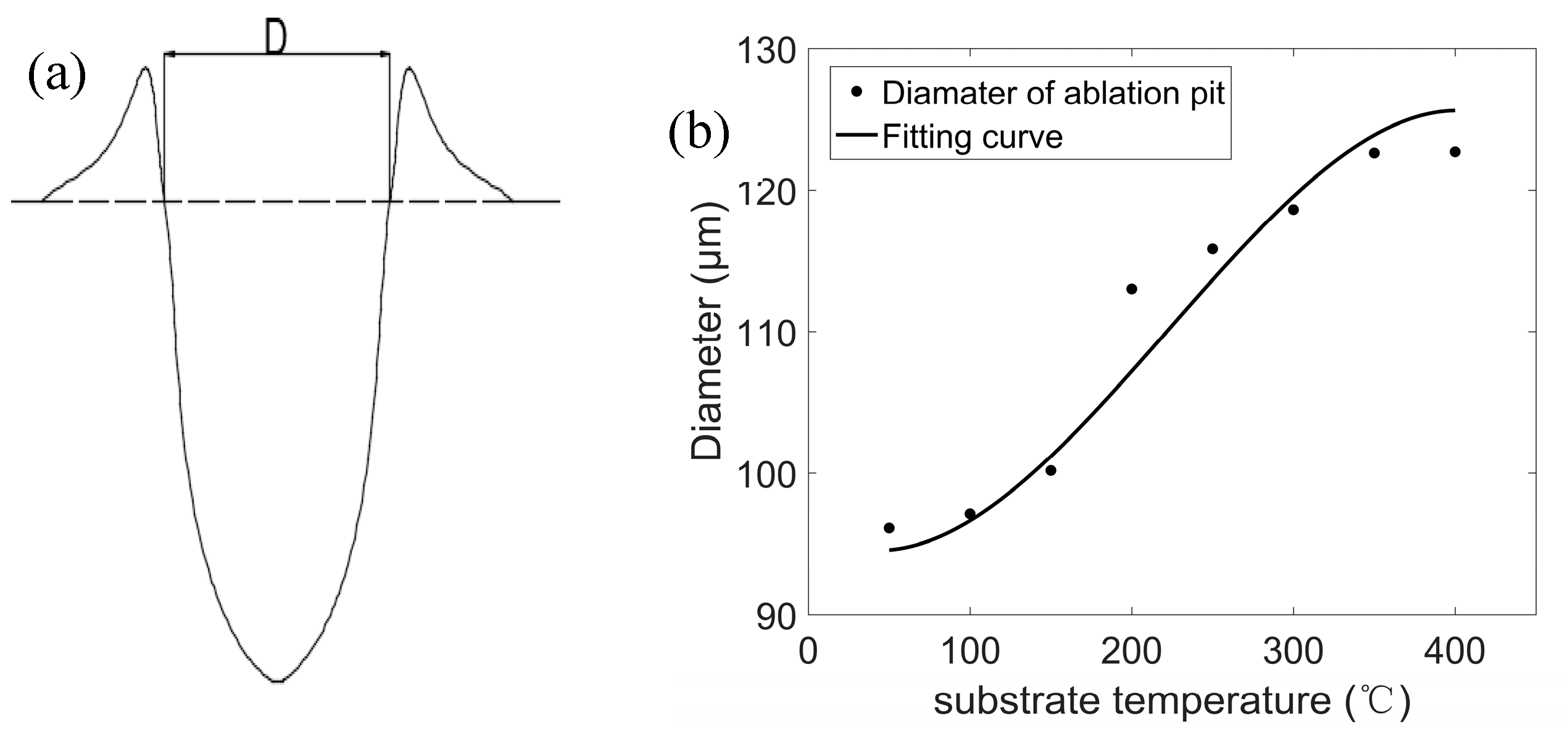
Figure 6.
Relationship between ablation depth and substrate temperature.
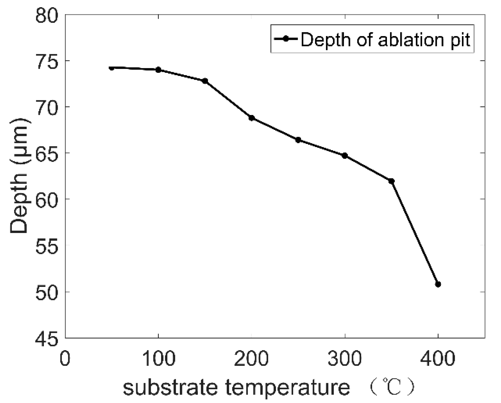
Figure 7.
Relationship between ablation efficiency ω and substrate temperature.
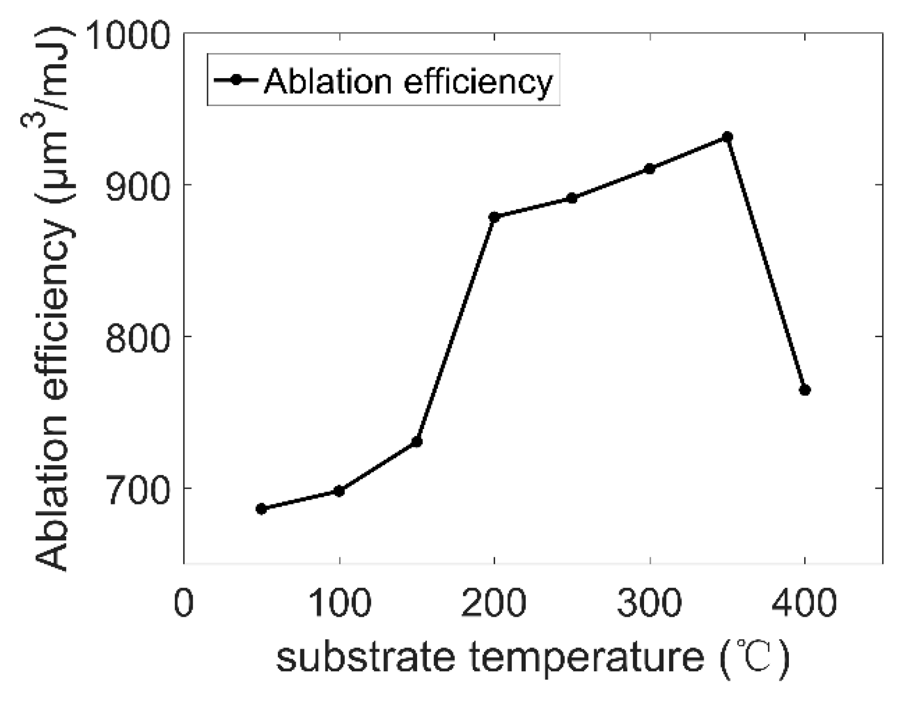
Figure 8.
Ablation crater morphology after irradiation of 2n (n = 0, 1, 2, 3, 4, 5) pulses at substrate temperatures of 50 °C. (a) 1 pulse; (b) 2 pulses; (c) 4 pulses; (d) 8 pulses; (e) 16 pulses; (f) 32 pulses.
Figure 8.
Ablation crater morphology after irradiation of 2n (n = 0, 1, 2, 3, 4, 5) pulses at substrate temperatures of 50 °C. (a) 1 pulse; (b) 2 pulses; (c) 4 pulses; (d) 8 pulses; (e) 16 pulses; (f) 32 pulses.
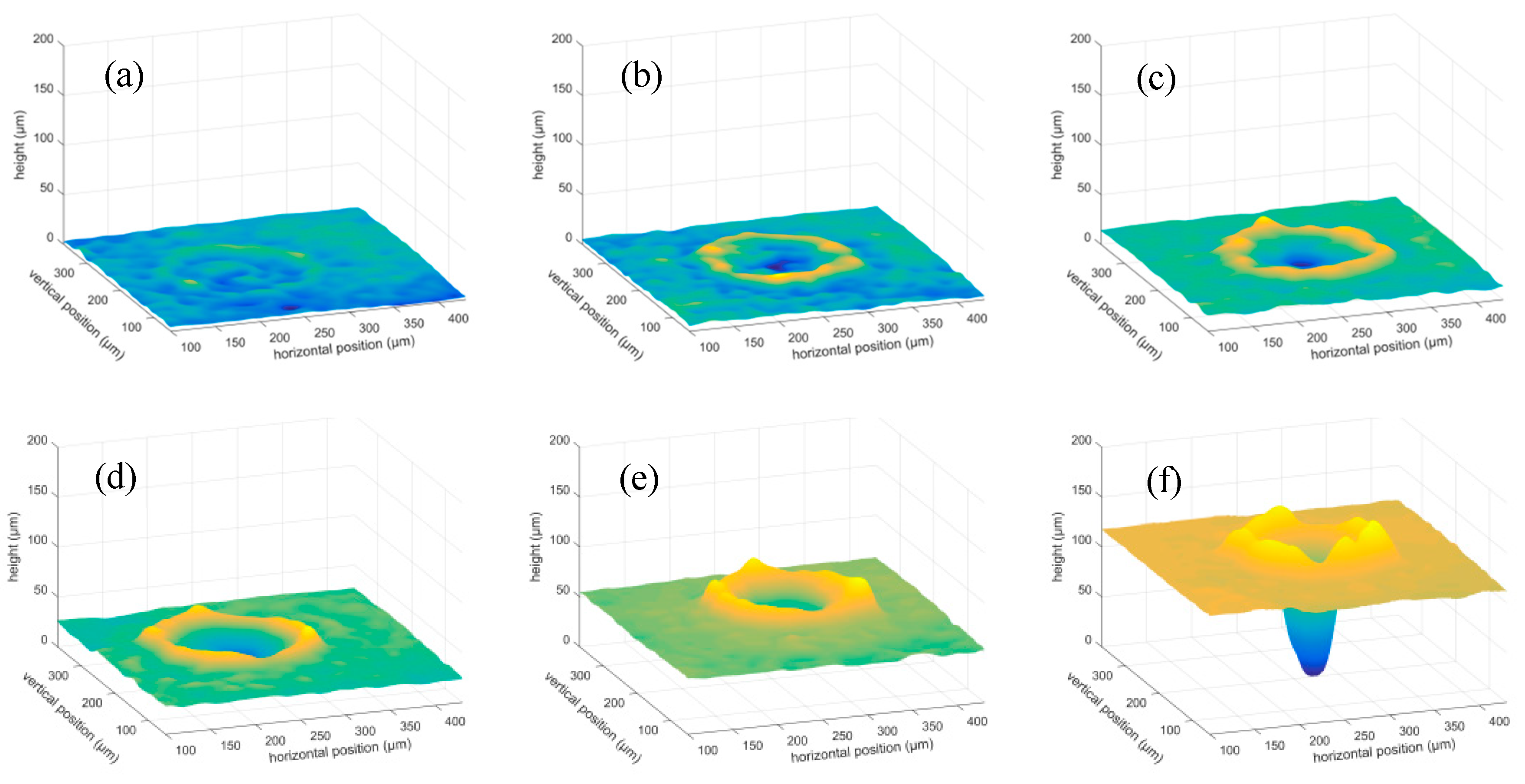
Figure 9.
Top-view optical microscope images of ablation craters after irradiation of 4 pulses at substrate temperatures of 50–400°C. (a) 50 °C; (b) 100 °C; (c) 150 °C; (d) 200 °C; (e) 250 °C; (f) 300 °C; (g) 350 °C; (h) 400 °C.
Figure 9.
Top-view optical microscope images of ablation craters after irradiation of 4 pulses at substrate temperatures of 50–400°C. (a) 50 °C; (b) 100 °C; (c) 150 °C; (d) 200 °C; (e) 250 °C; (f) 300 °C; (g) 350 °C; (h) 400 °C.
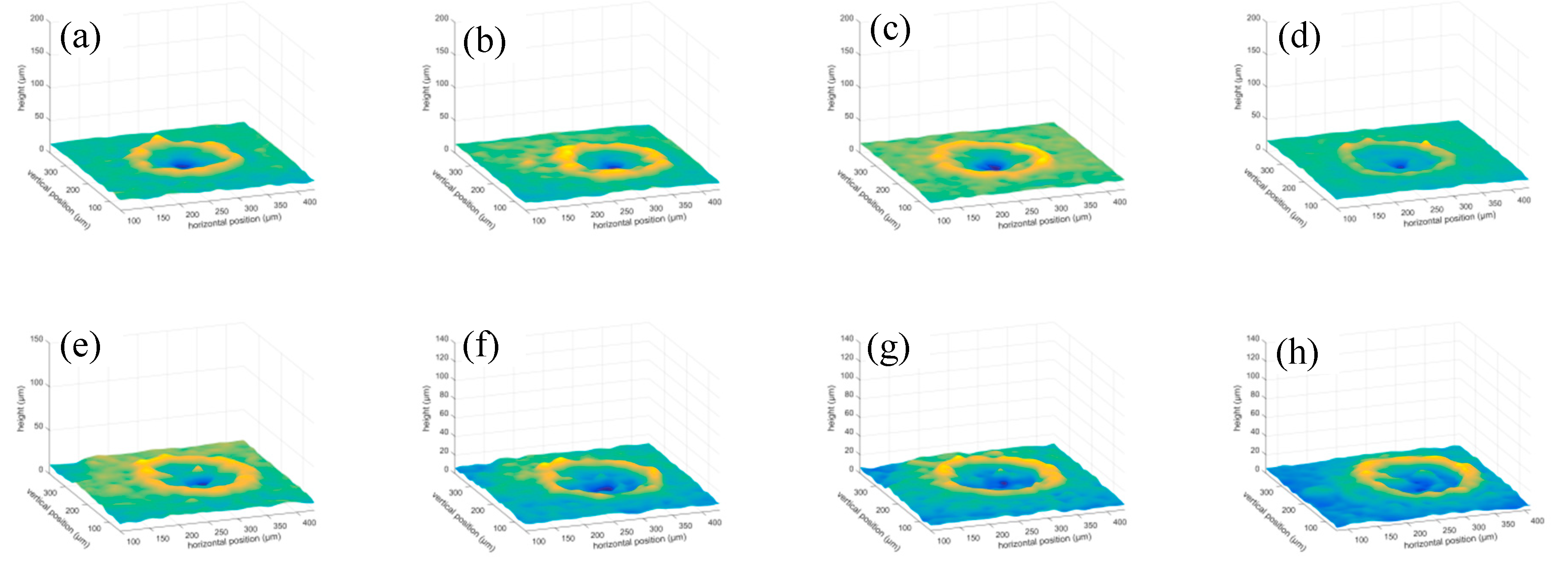
Figure 10.
Ablation craters’ cross section after irradiation of 32 pulses at different substrate temperatures. (a) 50 °C; (b) 100 °C; (c) 150 °C; (d) 200 °C; (e) 250 °C; (f) 300 °C; (g) 350 °C; (h) 400 °C.
Figure 10.
Ablation craters’ cross section after irradiation of 32 pulses at different substrate temperatures. (a) 50 °C; (b) 100 °C; (c) 150 °C; (d) 200 °C; (e) 250 °C; (f) 300 °C; (g) 350 °C; (h) 400 °C.
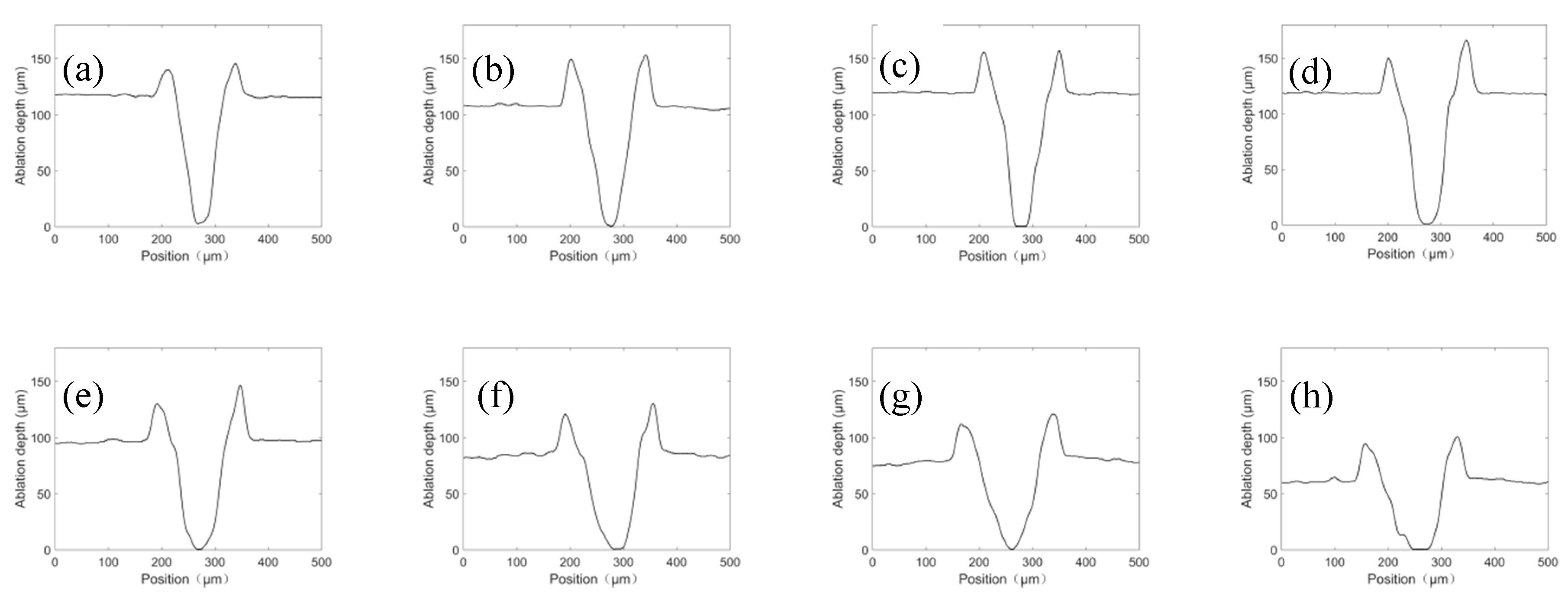
Figure 11.
Diameter of different pulse number.
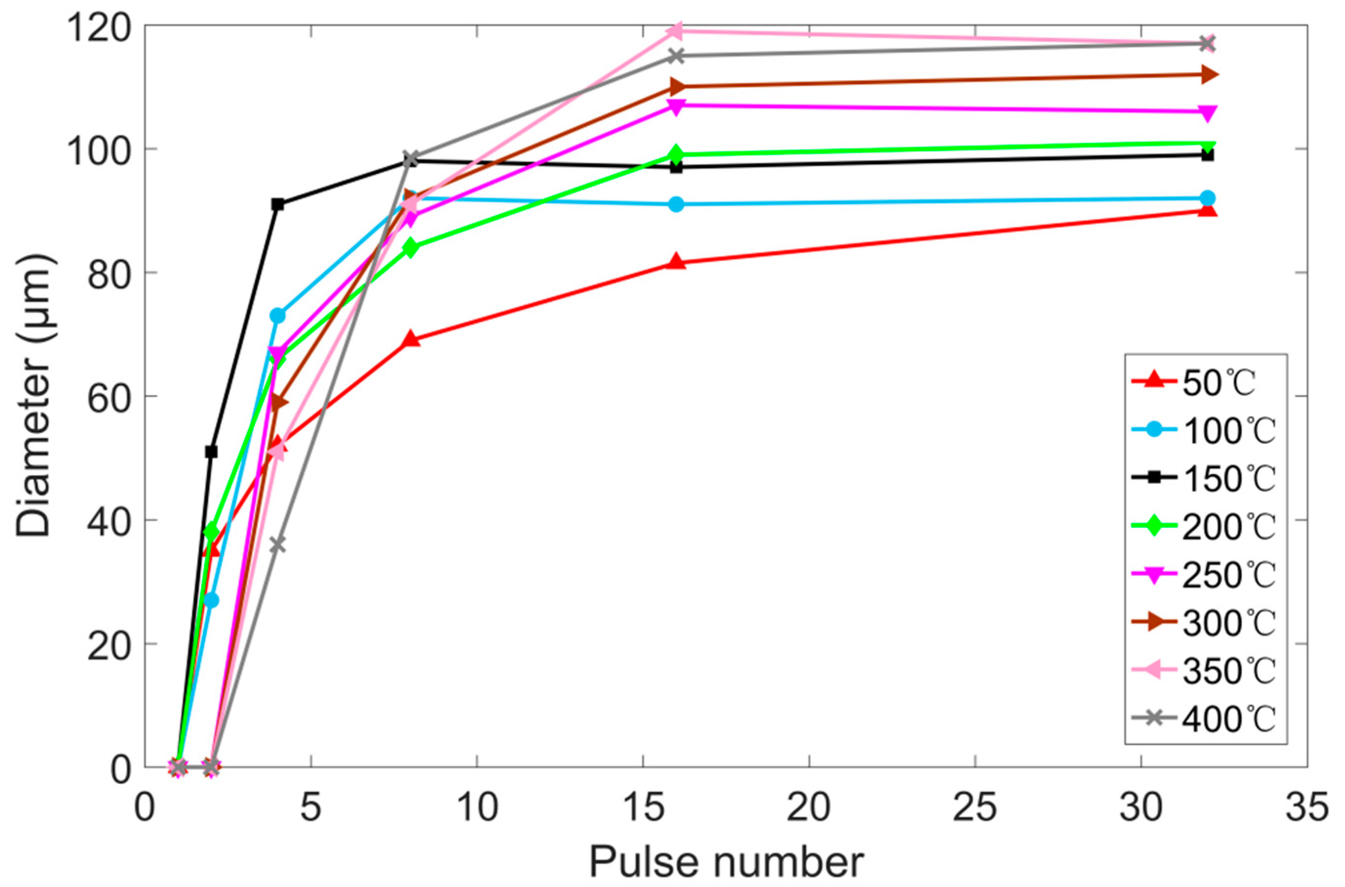
Figure 12.
Diameter of ablation craters under different substrate temperature.
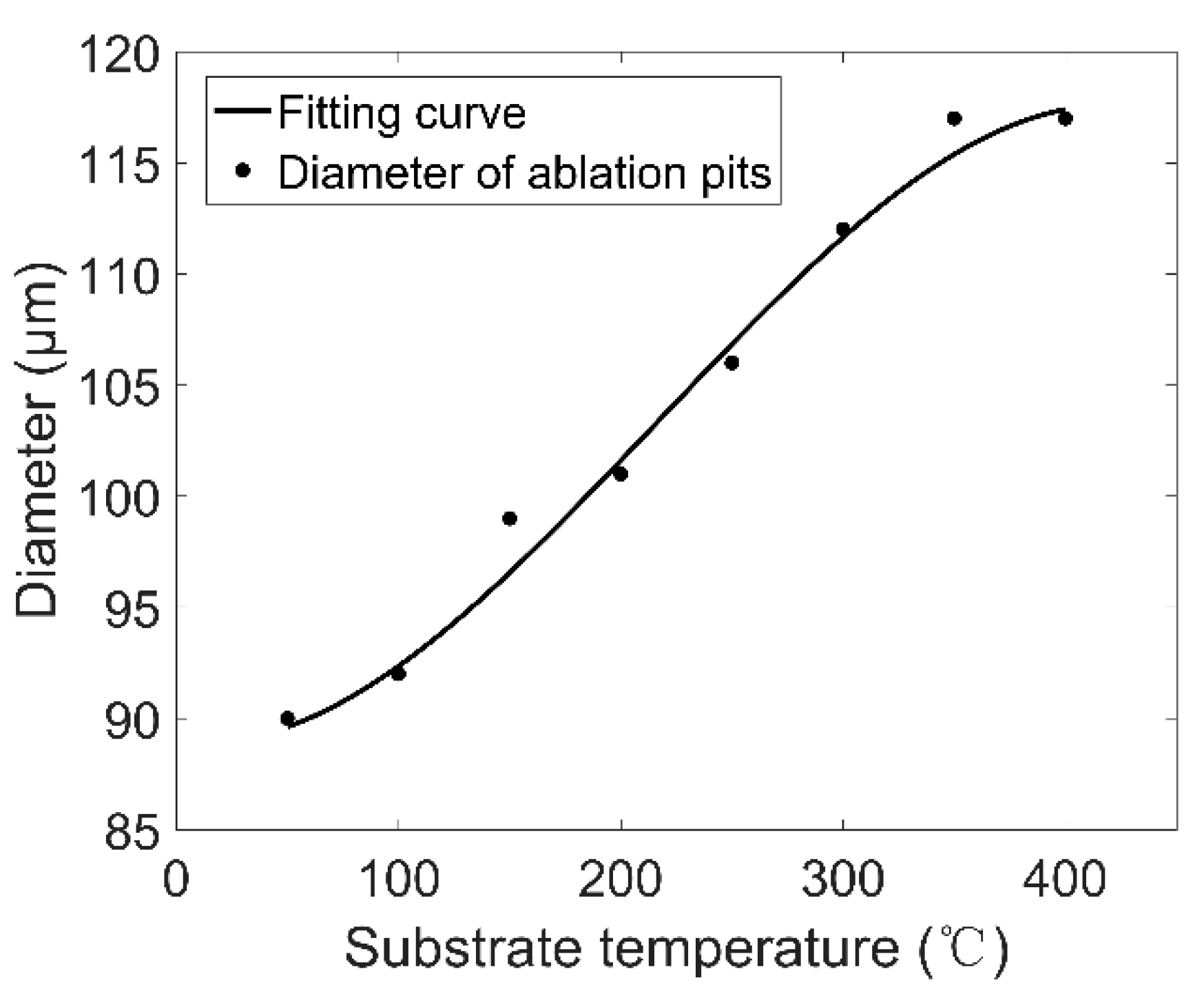
Figure 13.
Ablation depth–pulse number curves at substrate temperatures of 50 °C–400 °C.
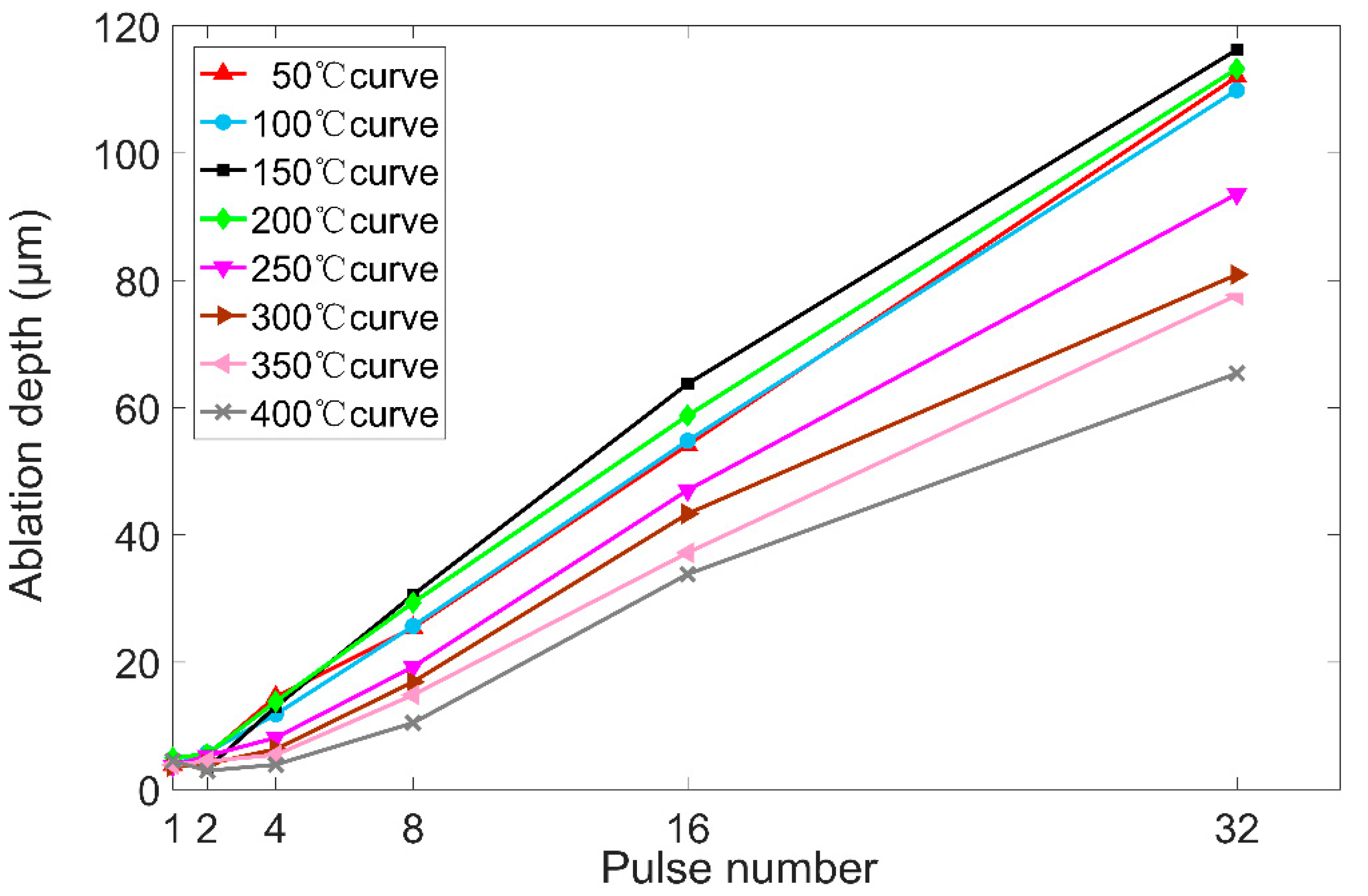
Figure 14.
Ablation depth–substrate temperature curves of 2n (n = 0, 1, 2, 3, 4, 5)-pulse irradiation.
Figure 14.
Ablation depth–substrate temperature curves of 2n (n = 0, 1, 2, 3, 4, 5)-pulse irradiation.
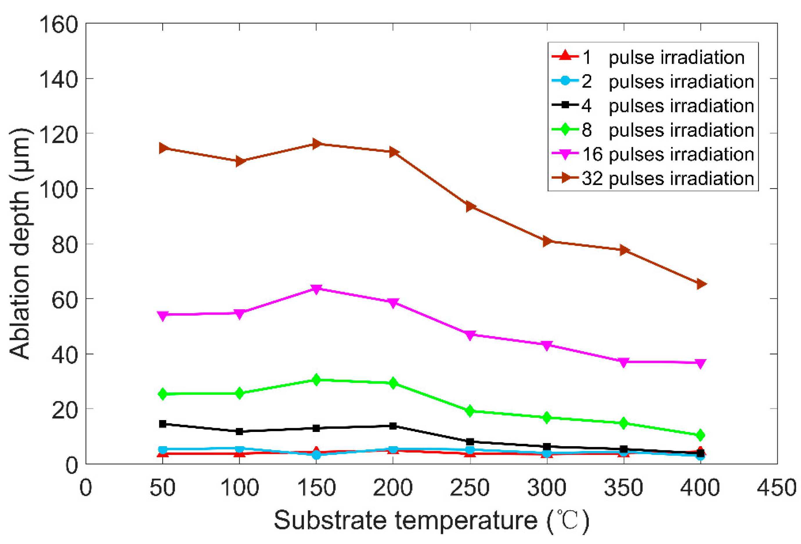
Figure 15.
Ablation efficiency ω of different pulse number.
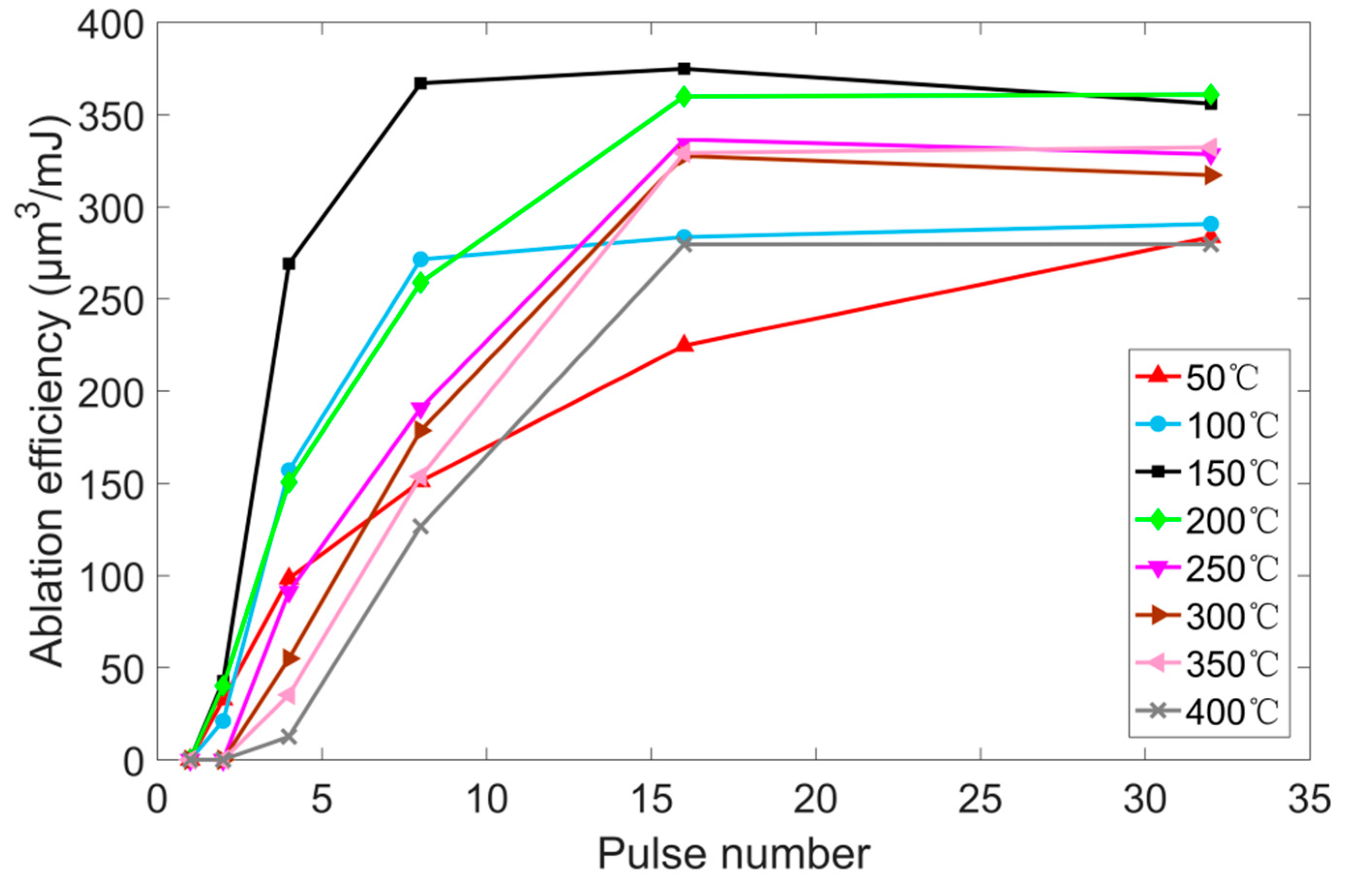
Figure 16.
Ablation efficiency ω after 32 pulses irradiation at substrate temperatures of 50–400 °C.
Figure 16.
Ablation efficiency ω after 32 pulses irradiation at substrate temperatures of 50–400 °C.

Table 1.
Chemical composition of Ti–6Al–4V.
| Element | Fe | Al | V | H | C | O | N | Ti |
|---|---|---|---|---|---|---|---|---|
| Content/% | ≤0.30 | 5.5–6.8 | 3.5–4.5 | ≤0.015 | ≤0.1 | ≤0.20 | ≤0.05 | remainder |
Table 2.
Laser parameters of experiment.
| Experiments | A | B |
|---|---|---|
| Laser type | Continuum Surelite I-10 | |
| Wavelength (nm) | 532 | |
| Repetition rate (Hz) | 10 | |
| Pulse width (ns) | 4–6 | |
| Beam diameter (unfocused) (mm) | 6 | |
| Spot diameter (focused) (μm) | 133.516 | |
| Laser energy (mJ) | 20 | 100 |
| Laser fluence (focused) (μJ/μm2) | 0.1429 | 0.7143 |
Table 3.
Ablation experiment data at 50 °C substrate temperature.
| No. | Laser fluence (μJ/μm2) | Pulse Number | Depth (μm) | Diameter (μm) | ω (μm3/mJ) |
|---|---|---|---|---|---|
| 1 | 0.7143 | 1 | 3.83 | 0 | 0 |
| 2 | 2 | 5.33 | 35 | 25.64 | |
| 3 | 4 | 14.55 | 52 | 77.25 | |
| 4 | 8 | 25.40 | 69 | 118.72 | |
| 5 | 16 | 54.12 | 81.5 | 176.46 | |
| 6 | 32 | 112 | 90 | 222.66 |
© 2020 by the authors. Licensee MDPI, Basel, Switzerland. This article is an open access article distributed under the terms and conditions of the Creative Commons Attribution (CC BY) license (http://creativecommons.org/licenses/by/4.0/).
Share and Cite
MDPI and ACS Style
Zhao, J.; Zhu, Z.; Xu, Y.; Song, X.; Wang, Y.; Peng, H.; Wang, Y.; Zuo, J.; Shu, X.; Yin, A. Nanosecond Laser Ablation of Ti–6Al–4V under Different Temperature. Appl. Sci. 2020, 10, 4657. https://doi.org/10.3390/app10134657
AMA Style
Zhao J, Zhu Z, Xu Y, Song X, Wang Y, Peng H, Wang Y, Zuo J, Shu X, Yin A. Nanosecond Laser Ablation of Ti–6Al–4V under Different Temperature. Applied Sciences. 2020; 10(13):4657. https://doi.org/10.3390/app10134657
Chicago/Turabian StyleZhao, Jiantao, Zhenge Zhu, Yacheng Xu, Xueyong Song, Yufan Wang, Hao Peng, Ying Wang, Jinrong Zuo, Xuedao Shu, and Anmin Yin. 2020. "Nanosecond Laser Ablation of Ti–6Al–4V under Different Temperature" Applied Sciences 10, no. 13: 4657. https://doi.org/10.3390/app10134657
Note that from the first issue of 2016, this journal uses article numbers instead of page numbers. See further details here.