Article

Numerical Evaluation of Structural Safety for Aged Onshore Wind Foundation to Extend Service Life

Infrastructure Safety Research Institute, Korea Institute of Civil Engineering and Building Technology, Goyang-Si, Gyeonggi-Do 10223, Korea
*
Author to whom correspondence should be addressed.
Appl. Sci. 2020, 10(13), 4561; https://doi.org/10.3390/app10134561
Submission received: 20 May 2020 / Revised: 23 June 2020 / Accepted: 27 June 2020 / Published: 30 June 2020
(This article belongs to the Special Issue Advances on Structural Engineering)

Abstract

:
In this paper, for the case of “service life extension” with the same capacity for wind turbines, a structural safety evaluation was carried out to determine whether to extend the service life of the aged foundation. As a result of this study, it was found that the aged foundation satisfies the structural safety of material strength, ultimate strength, fatigue life, and serviceability up to the present. Although the in-service period has been over 16 years, it has been shown that the material properties of concrete have exceeded the design strength, and no significant material deterioration has occurred. Also, structural safety could be evaluated more realistically based on actual concrete properties. In particular, it has been shown that it has a fatigue life of 40 years or more, so service life can be extended. It is expected that the methodology used in this paper will be useful not only for structural safety evaluation of the foundation in service, but also for decision-making for extending the service life. Furthermore, a more technical approach should be explored by many researchers in the future.

1. Introduction

Wind energy is drawing attention worldwide as a representative renewable energy source. Wind energy can be easily obtained from natural wind resources, but creating a new wind farm is never an easy task. A long period of time, from site selection to planning, civil affairs, licensing, financing, and construction, requires a very difficult and complicated process for many people to create a new wind farm. Wind farms constructed in such a difficult way are not able to operate indefinitely (power generation). In general, the service life of a wind turbine is about 20 years, and wind turbines that have reached the service life can no longer be operated and should be decommissioned. As a result, it is common sense that the wind farm composed of many wind turbines should also be decommissioned after a certain period of time, about 20 years [1].
However, it is very nationally and socially wasteful to decommission of a wind farm after the wind turbine has reached the end of its service life. Currently, the wind farms in operation were built in the early days of wind power generation, and are mostly located in areas with excellent wind resources. Therefore, not having wind power generation again in these regions is also a national waste of energy resources. Namely, in order to successfully achieve the renewable energy plan promoted by the governments of each country, it is important to continue the wind power generation without destroying the wind farms currently in operation, as well as to construct a new wind farm [2], as presented in Figure 1 [3,4]. This is also because it is very difficult to find new candidates for wind farms because regions with abundant wind resources are limited [1,2].
In this paper, we discuss the method of structural safety evaluation and re-use of the onshore wind foundation in the case of the use of wind turbines after the service life and in the case of unexpected damage to the foundation during the service life.

2. Service Life Extension of Onshore Wind Foundation

2.1. Service Life Extension or Re-Use

There are three methods to re-use the aged onshore wind foundation during or after the service life of the wind turbine [1,3,4]. Firstly, the service life of the onshore wind turbine is about 20 years. During the in-service life, the wind foundation will continue to receive turbine loads. As a result, unexpected damage to the foundation may occur during the in-service life, and in this case, it is desirable to continue using the damaged foundation appropriately by “retrofit” [5].
Secondly, the service life of the wind turbine is about 20 years, but the wind foundation is designed to support the external force (wind load, etc.) of the return period of 50 years. Furthermore, it is known that the fatigue life of the concrete members such as the wind foundation is infinite. In this case, if it is possible to extend the service life of the aged wind turbine by replacing old components with new ones, it is possible to continue to use the aged foundation for an additional period of time, as presented in Figure 2a This method is called “service life extension” [6,7].
Thirdly, after 20 years of service life of the existing wind turbine, it can be also re-used to support the new wind turbine. Compared to the decades ago when the existing wind farms were built, the development of wind turbine technology has led to a dramatic improvement in turbine power generation capacity [7]. In order to support these modern larger capacity turbines, aged foundations are retrofitted and re-used to support larger turbine loads, as presented in Figure 2b. This method is called “partial repowering” [3,4,8,9,10,11]. This is different from “full repowering”, where all the existing foundations are removed from the same site and then all of the wind farm components, including the foundations, are reconstructed to fit large capacity turbines, as presented in Figure 2c.
In order to extend the service life or re-use an aged onshore wind foundation through the three methods described above, a structural safety evaluation using an engineering method is firstly performed on the wind foundation, and, if necessary, an appropriate structural retrofit should be made according to the result of the structural safety evaluation [8,9]. Against this background, the need for technology development has recently been raised. In this paper, for the case of “service life extension” with the same capacity for the wind turbine, a study was conducted on the methodology of structural safety evaluation to determine whether to extend the service life of the aged foundation.

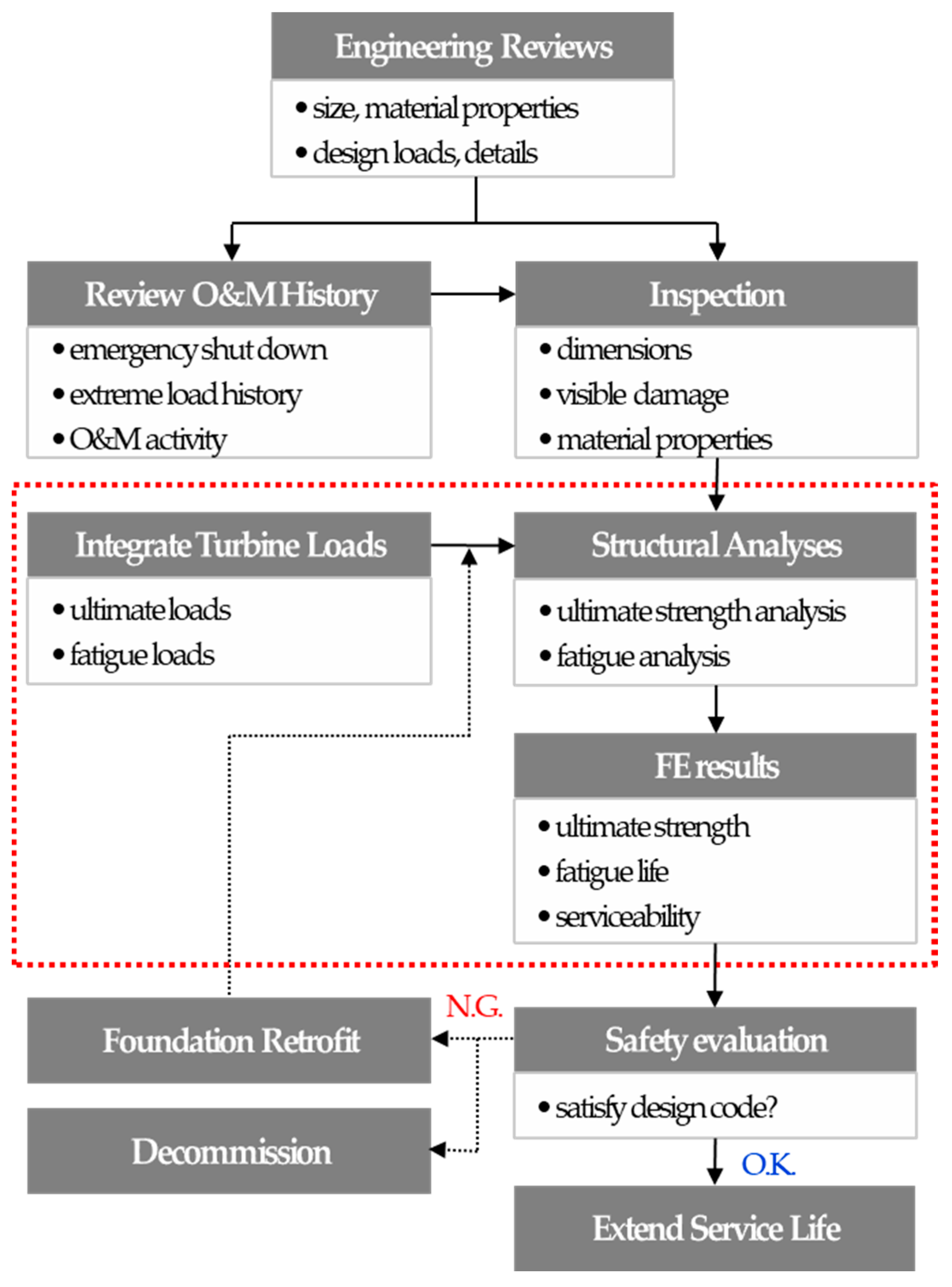
2.2. Decision Making Process for Structural Safey Evaluation

The structural safety evaluation of the aged foundation of this study was conducted on the in-service wind farm of service life 16 years. Figure 3 shows the procedure for structural safety evaluation and the decision-making process for the service life extension or re-use of the aged foundation. In this paper, only the structural safety of the anchor ring type foundation was evaluated, and the retrofit method of the aged foundation was not included.
In order to evaluate the structural safety of the onshore wind foundation in-service, it is necessary to first review the design documents. However, in-service onshore wind farms were built in the early days of wind power generation, and most of the design documents are not available. In addition, it is known that, in the early days of onshore wind power, design methodology for wind foundations, FE fatigue analysis tools for concrete members, etc., were not properly established. Therefore, fatigue life was also not evaluated for the foundations. It was considered general technical common sense at that time that the concrete members do not require fatigue life evaluation because the concrete members are highly resistant to fatigue; namely, there is almost no fatigue damage.
Next, in order to evaluate the structural safety of an aged foundation to decide the service life extension, the material aging effect (deterioration in strength, etc.) of concrete is evaluated. Based on this, it is necessary to evaluate the structural safety of the foundation against extreme turbine loads. This is because, depending on the material aging effect (deterioration in strength, etc.) of the foundation concrete during the in-service period, it is determined whether the ultimate strength required for the service life extension is satisfied. Also, it is necessary to evaluate the fatigue life of the foundation to decide whether it is possible to extend service life, since, as described above, it is known that the fatigue life evaluation of the foundation was not performed in the early days of the onshore wind farm. In addition, a review of overturning and sliding, which are structural design items, should be evaluated.
Based on the results of the structural safety evaluation, a decision is made on the possibility of service life extension of in-service wind foundation. If the structural safety result satisfies the current design criteria for the onshore wind foundation, it is possible to extend the service life, and if not, an appropriate structural retrofit or decommission is decided. Another problem is that there are no documents on the design method applied to the design of the aged wind foundation 16 years ago. The design methods of the onshore wind foundation include the allowable stress design method, the strength design method, and the limit state design method, and the limit state design method is widely used at present. Therefore, a structural safety evaluation of this study was performed in accordance with the current limit state design method.

2.3. Targeted Onshore Wind Foundation

The spread footing is a common foundation type of the onshore wind turbine. This foundation type is subdivided according to how the tower is connected to the foundation [3,4]. There is an “anchor ring-type” in which the tower is embedded into the foundation, and an “anchor rod-type” in which the tower and the foundation are connected by anchor bolts. In this paper, structural safety evaluation was performed for the anchor ring type, as presented in Figure 4. This is because this type was applied to many sites during the introduction of onshore wind farms in South Korea, and the need to extend service life or re-use it has been steadily raised. The specification of the targeted wind turbine of this study was presented in Table 1, and the integrated turbine load was indicated in Figure 4a, where integrated turbine load means the ultimate (extreme) turbine load, including the safety margin of 1.3 as the load factor.
The anchor ring type has the advantage of improving the overturning resistance of the tower because the bottom end of the tower is embedded in the foundation. However, it is known that the tower vibration caused by the turbine load directly acts on a connection part of the foundation, and this type of connection part is vulnerable to damage. In the past, the turbine capacity and the tower size were not large, so the turbine load acting on the connection part of this foundation was not large enough to damage the foundation. However, it has been known that in recent years, due to the enlargement of the wind turbine capacity, the turbine load acting on the connection part of the foundation increases, causing direct damage to the foundation of this type.

3. Structural Safety Evaluation for Aged Wind Foundation

3.1. Concrete Material Test

In order to evaluate concrete material properties, destructive testing by core drilling as well as non-destructive testing by Schmidt hammer was carried out. However, the concrete properties obtained by destructive testing were judged to be more accurate, and this property was used in structural safety evaluation of this paper. Alternatively, if concrete core drillings are not available in the practical problem, the properties by non-destructive testing may be used.
First, concrete cores were collected for the foundation of an in-service wind farm located in Jeju of South Korea. A concrete core was collected for the foundation where the turbine was demolished due to some recent problem. In the same wind farm, multiple turbines with the same turbine and foundation are still in service. By using these concrete cores, concrete material safety including compressive strength, modulus of elasticity, and ultrasonic measurement were evaluated, as presented in Figure 5. Three concrete cores were collected for each unit of the two foundations, having the same site, the same service life, and the same wind turbine. The material safety in terms of strength was evaluated using the average of the values measured from these cores. As a result of the material safety evaluation, it was found that the concrete compressive strength (fm) of the foundation was maintained at a materially sound state, such as 39.3 to 41.9 MPa, which exceeded the design strength (fd) of 30 MPa, as indicated in Table 2. The material safety of concrete was evaluated as follows, and it was found that the concrete strength was 1.35 times higher than the design strength.
Rm = fm/fd
At this time, the concrete compressive strength by the destructive test (fm) was utilized as a concrete material property in the ultimate strength evaluation by numerical analysis in Section 3.2, so that the structural safety of the foundation reflecting the in-situ concrete condition could be evaluated [3].

3.2. Ultimate Strength

Using the results of the material strength evaluation for the in-service foundation concrete, it was evaluated whether or not the ultimate strength of the foundation was satisfied for the current turbine load [12,13,14,15]. The ultimate strength was evaluated by numerical analysis by FE analysis program DIANA [16] reflecting the in-situ concrete compressive strength indicated in Table 2. DIANA software has advantages in the nonlinear analysis of complex concrete members such as onshore wind foundations since it has various modeling and physical property modules for the concrete members. The yield strengths of the anchor ring and reinforcing rebar were 240 and 400 N/mm2, respectively. The structural members constituting the foundation such as the concrete, reinforcement, and anchor ring were modeled as realistically as possible [17], as shown in Figure 6. Concrete foundations and anchor rings were modeled as solid elements, and reinforcing bars were modeled using embedded reinforcement elements. The tower was not modeled separately, but only the extreme load acting on the bottom of the tower was applied to the top of the anchor ring, as presented in Figure 4a. For the concrete material model, the total strain crack model considering the compressive behavior and the tensile behavior (fracture energy-based) was used.
For the evaluation of the bearing capacity of the soil layer, the soil layer of the bottom of the foundation was modeled using a compressive spring [3,12], as presented in Figure 6, for which the reaction force is to be subjected to the foundation bottom only when the foundation and the ground are in contact with each other, as presented in Figure 4a. The ultimate turbine load for the structural safety evaluation of the foundation was provided by the turbine company, and the specifications of the foundation were provided by the authority of the wind farm.
At first, critical points for each structural member of the concrete, reinforcement, anchor ring were selected through pre-analysis. As a result of pre-analysis, critical points of the tension part of the foundation were distributed around the concrete crushing cone resisting pull-out from the anchor ring plate, as presented in Figure 6 and Figure 7a. Also, critical points of the compression part of the foundation were distributed around the concrete crushing cone that resists compaction under the anchor ring plate, as presented in Figure 6 and Figure 7a. Then, the maximum stresses in these critical points were evaluated by applying the ultimate turbine load. The structural safety for the ultimate strength was evaluated by comparing the maximum stresses (fmax) at critical points and the yield strengths (fy) of each material.
Rf = fmax/fy
As a result of the evaluation, as indicated in Figure 7 and Table 3, the maximum stress ratios (actual strength/design strength) for each structural member such as concrete, reinforcement, anchor ring were 0.49 or less, indicating that ultimate strength safety was maintained.

3.3. Fatigue Life

Fatigue life was evaluated by performing fatigue analysis by FE analysis program ANSYS [18], which is widely used for fatigue analysis of various structures including the concrete members, using the equivalent fatigue load of the in-service wind turbine. In the DNV-GL guidelines [19] for fatigue life, it is recommended to use a fatigue load corresponding to negative inverse slope m = 3 of the S-N curve when the number of fatigue load cycles is 107 or less. Also, it is recommended to use a fatigue load corresponding to negative inverse slope m = 5.0 of the S-N curve when the number of fatigue load cycles exceeds 107 [19]. The purpose of this section is to evaluate the overall fatigue life of the in-service foundation. Therefore, it was evaluated by applying a fatigue load corresponding to negative inverse slope m = 3.0 until 20 years because it was subjected to a cycle fatigue load of 107 or less until 20 years. Fatigue life after 20 years was evaluated by applying a fatigue load corresponding to the negative inverse slope m = 5.0, as indicated in Table 4.
The S-N curve for each material used in fatigue life evaluation is provided in Figure 8. In the case of concrete, the S-N curve of the FIB model [18,20] was applied, and in the case of steel, the S-N curve of A36 steel with a yield strength of 40 MPa, which is the same as the reinforcing bar (HD25 to 29) applied to the aged concrete foundation, was applied [18]. The average fatigue stress theory for each structural member to evaluate fatigue life is as follows. For the steel, Goodman’s theory [18,21] is applied to obtain stable results for low-ductility metals. For the concrete, the Soderberg theory [18,22,23] is applied, which is known to be more conservative than the Goodman theory and suitable for brittle materials such as the concrete.
In this paper, fatigue life was evaluated using the concept of the “Fatigue Safety Index [18]” in the corresponding year, represented by the following equation, where if the fatigue safety index is 1.0 or over, it means that it is safe for fatigue life.
Fatigue Safety Index = Fatigue allow stress/Fatigue stress
The service life used for fatigue life evaluation was targeted at two cases: the service life to now (16 years) and the service life up to 40 years. The fatigue load corresponding to m = 3 was applied in the fatigue life evaluation for the service life up to now, and the fatigue load corresponding to m = 5 was applied to the fatigue life evaluation up to service life 40 years. The fatigue safety index of the foundation was evaluated for each of the most critical areas for tension and compression for each structural member, respectively, as presented in Figure 9. As a result of fatigue life evaluation, the minimum fatigue safety indexes of steel and concrete for the equivalent fatigue load of m = 3.0 were 2.93 and 1.88, respectively, as presented in Figure 10. The minimum fatigue safety indexes for the equivalent fatigue load of m = 5.0 were 1.76 and 1.21, respectively, as presented in Figure 11. In summary, the in-service foundation showed that the fatigue safety index of up to 40 years of service life was 1.0 or higher for the in-service turbine fatigue load, thereby securing a fatigue life of 40 years or more.

3.4. Soil Resistance, Overturning, and Sliding

(1) Soil resistance
The onshore wind foundation should be installed on a good soil layer, and it is important to ensure the bearing capacity of the soil layer against the maximum vertical load acting on the foundation ground. In other words, the vertical ground reaction force generated on the bottom of the foundation due to the ultimate turbine load should lie below the allowable bearing capacity of the foundation ground [13,14,15].
In this paper, the soil resistance of foundation soil layer was evaluated by comparing the maximum vertical load (qmax) generated at the bottom of the foundation with the allowable bearing capacity (qa) of the foundation ground calculated by the design criteria [13,14,15], as indicated in Equation (4). The targeted ground condition of this study is soft rock (basalt), and the allowable bearing capacity of this soil layer is given as 200 kN/m2 in the design condition.
Rq = qmax/qa
As a result of the evaluation, the maximum vertical reaction force generated on the bottom of the foundation resulted in 74.1 kN/m2, and the allowable bearing capacity of the foundation soil layer was calculated to be 200 kN/m2 by design condition. Therefore, the maximum vertical reaction force generated on the bottom of the foundation due to the ultimate turbine load was estimated to be about 37% of the allowable bearing capacity of the foundation soil layer and the supporting resistance of the soil layer was evaluated to be sufficient.
(2) Overturning
Another important aspect of the safety of the onshore wind foundation is overturning. It is important to secure the overturning resistance to the maximum overturning moment generated in the foundation by the turbine load [24]. In other words, the overturning moment generated on the bottom of the foundation due to the ultimate turbine load should lie below the allowable overturning capacity of the foundation [13,14,15].
In this paper, the overturning safety of foundation was evaluated by comparing the maximum overturning moment (Mmax) generated at the bottom of the foundation with the allowable overturning capacity (Ma) of the foundation calculated by the design criteria [13,14,15], as indicated in Equation (5). The allowable overturning capacity means the resistance to overturning is only from the self-weight of the foundation and it can be easily calculated by multiplying the total self-weight of the foundation and the overturning moment arm length.
RM = Mmax/Ma
As a result of the evaluation, the maximum overturning moment generated on the bottom of the foundation resulted in 10,473 kN-m and the allowable overturning capacity of the foundation was calculated to be 21,881 kN-m by the design criteria. Therefore, the maximum overturning moment generated on the bottom of the foundation due to the turbine load was estimated to be about 48% of the allowable overturning capacity of the foundation and the overturning safety of foundation was evaluated to be sufficient.
(3) Sliding
It is important to secure the sliding resistance of the foundation against the lateral load generated by the ultimate turbine load. The sliding of the onshore wind foundation resists only by the frictional force on the bottom of the foundation. Therefore, the maximum shear force generated on the bottom of the foundation due to the ultimate turbine load should lie below the allowable shear (frictional) force of the foundation ground [13,14,15].
In this paper, the sliding safety of foundation was evaluated by comparing the maximum shear force (Vmax) generated at the bottom of the foundation with the allowable shear (frictional) force (Va) of the foundation ground calculated by the design criteria [13,14,15], as indicated in Equation (6). The targeted ground condition is soft rock (basalt), and the allowable shear (frictional) force of this soil layer is given as 2722 kN (including safety factor 1.2) in the design condition.
RV = Vmax/Va
As a result of the evaluation, the maximum shear force generated on the bottom of the foundation resulted in 266 kN and the allowable shear (frictional) force of the foundation was calculated to be 2722 kN by the design criteria. Therefore, the maximum shear force generated on the bottom of the foundation due to the ultimate turbine load was estimated to be about 10% of the allowable shear (frictional) force of the foundation and the sliding safety was evaluated to be sufficient.

3.5. Summary of Structural Safety Evaluation

As a result of structural safety evaluation for the aged onshore wind foundation, it was found that the existing foundation satisfies structural safety such as ultimate strength, fatigue life, and serviceability, as well as material safety in strength for the in-use turbine load, as provided in Table 5. It was found that the material strength of the foundation had a safety margin of 35%, the ultimate strength of about 51%, fatigue life of about 20 years or more, and stability (overturning and sliding) of about 52%. It is considered that the result of structural safety evaluation of this study was partly contributed by the review of the limit state design method currently in use because the design method applied when it was first constructed is not known. In particular, the fatigue life is the most important item to determine the service life extension of the foundation because the foundation is continuously damaged by turbine loads depending on the service life [24,25]. As a result of evaluating the fatigue life of the turbine load, it has been shown that it has a fatigue life of 40 years or more, so that service life can be extended.

4. Conclusions

In order to extend the service life or re-use of an onshore wind foundation, a structural safety evaluation using an engineering method is firstly performed on the wind foundation. In this paper, for the case of “service life extension” with the same capacity of the wind turbine, the structural safety evaluation was carried out to determine whether to extend the service life of the foundation. The structural safety evaluation of this study was conducted on the in-service wind farm of service life 16 years with the anchor ring foundation. The structural safety evaluation was carried out on six items which are essential for confirming the safety of foundation, such as material strength, ultimate strength, fatigue life, soil resistance, overturning, and sliding.
As a result of structural safety evaluation for the onshore wind foundation, it was found that the existing foundation satisfies the structural safety of the ultimate strength, fatigue life, and serviceability. Although the in-service period has been over 16 years, it has been shown that the material properties of the concrete have exceeded the design strength and no significant material deterioration has occurred. Also, the structural safety metrics, such as the ultimate strength and fatigue life, could be evaluated more realistically based on actual concrete properties. In particular, the fatigue life is the most important item to determine the service life extension of the foundation, because the foundation is continuously damaged by turbine loads depending on the service life. As a result of evaluating the fatigue life of the turbine load, it has been shown that it has a fatigue life of 40 years or more, so that service life can be extended.
In addition, it is expected that the methodology used in this paper will be useful not only for safety evaluation of the foundation in service but also for decision-making for extending the service life. At present, when the technical data in this area is insufficient, the appropriate method is to determine the service life of the foundation depending on whether it satisfies the current design criteria. However, a more technical approach should be explored by many researchers in the future, and this paper has carried out one of those efforts.

Author Contributions

Y.-J.J. is a PI of the research project who planned most of the structural safety evaluation program and is a main writer of the paper; M.-S.P. performed fatigue life evaluation; S.-H.S. carried out ultimate strength and serviceability evaluation; J.K. assisted with the material test and FE analysis. All authors have read and agreed to the published version of the manuscript.

Funding

This research was funded by [the Ministry of Trade, Industry, and Energy of South Korea] grant number [20183010025110].

Acknowledgments

This study was supported by the Ministry of Trade, Industry, and Energy of South Korea, Project No: 20183010025110 (Development of repowering total technology to improve availability of old wind farm).

Conflicts of Interest

The authors declare no conflict of interest.

References

  1. Lantz, E.; Leventhal, M.; Baring-Gould, E.I. Wind Power Project Repowering: Financial Feasibility, Decision Drivers, and Supply Chain Effects; NREL/TP-6A20-60535; Office of Scientific and Technical Information (OSTI): Golden, CO, USA, 2013. [Google Scholar]
  2. European Wind Energy Association. Wind in Power–2015 European Statistics; EWEA: Brussels, Belgium, 2016. [Google Scholar]
  3. Connaghan, B.; DeCristofaro, E.; Soderlund, E.; Thibodeau, M.; Wang, X. White Paper: Wind Project Repowering; Sargent & Lundy: Chicago, IL, USA, 2017. [Google Scholar]
  4. DNV-GL. White Paper on Technical and Contractual Considerations in Partial Repowering of Wind Turbines; EAA-WP-07; DNV-GL: Oslo, Norway, 2016. [Google Scholar]
  5. He, M.; Bai, X.; Ma, R.; Huang, D.; Liu, H. Field experimental study on the retrofit of cracked onshore wind turbine foundations using externally prestressed anchor bolts. Struct. Concr. 2017, 19, 864–875. [Google Scholar] [CrossRef]
  6. Ziegler, L.; Elena Gonzalez, E.; Rubert, T.; Smolka, U.; Melero, J. Lifetime extension of onshore wind turbines: A review covering Germany, Spain, Denmark, and the UK. Renew. Sustain. Energy Rev. 2018, 82, 1261–1271. [Google Scholar] [CrossRef] [Green Version]
  7. U.S. Energy Information Administration. Annual Electric Generator Report; U.S. Energy Information Administration: Washington, DC, USA, 2016.
  8. Byrne, A. Trends, technical risks and opportunities in partial repowering. In Proceedings of the AWEA Wind Project O&M and Safety Conference 2017, San Diego, CA, USA, 28 February–1 March 2017. [Google Scholar]
  9. DeCristofaro, E.; Sargent & Lundy. Wind project partial repowering: Key considerings and insights. In Proceedings of the AWEA WindPower Conference 2018, Chicago, IL, USA, 7–10 May 2018. [Google Scholar]
  10. Waldron, S.; Smith, J.; Taylor, K.; McGinnes, C.; Roberts, N.; McCallum, D. Repowering onshore wind farms: A technical and environmental exploration of foundation reuse. In Carbon Landscape and Drainage Knowledge Exchange Network-Led Report; Construction Scotland Innovation Centre: Glasgow, UK, 2018. [Google Scholar]
  11. Salzgitter, A. K-Tower Repowering Concept. 2020. Available online: www.szmr.de/en/supply-program/system-solutions/k-tower/k-tower-repowering-concept.html (accessed on 20 May 2020).
  12. Hassanzadeh, M. Cracks in onshore wind power foundations: Causes and consequences. Elforsk 2012, 11, 56. [Google Scholar]
  13. ACI Committee 349. Code Requirements for Nuclear Safety-Related Concrete Structures and Commentary; American Concrete Institute: Farmington Hills, MI, USA, 2013. [Google Scholar]
  14. DNV-GL. Support Structures for Wind Turbines; DNVGL-ST-0126; DNV GL: Oslo, Norway, 2016. [Google Scholar]
  15. Japan Society of Civil Engineers. Guidelines for Structural Design of Supports for Wind Power Facilities; JSCE: Tokyo, Japan, 2010. [Google Scholar]
  16. Frits, C.W.; Peter, H.F. DIANA User’s Manual: Nonlinear Analysis-Release 7; TNO build. and construct.: Delft, The Netherlands, 1998. [Google Scholar]
  17. Song, S.; Jeong, Y.; Park, M.; Kim, J. Nonlinear structural analysis of embedded ring foundations for partial repowering of aging onshore wind turbines. J. Wind Energy 2019, 10, 35–42. [Google Scholar]
  18. ANSYS. ANSYS User’s Manual: Theory Reference Release 5.6; ANSYS Inc.: Bengaluru, India, 1999. [Google Scholar]
  19. DNV-GL. DNVGL RP-C203: Fatigue Design of Offshore Steel Structures; DNV-GL: Oslo, Norway, 2014. [Google Scholar]
  20. Fib International. Fib Model Code for Concrete Structures 2010; Fib International: Lausanne, Swiss, 2013. [Google Scholar]
  21. Hattori, T. Fatigue strength and life estimation methods using critical distance stress theory. Glob. J. Eng. Sci. 2019, 2, 1–9. [Google Scholar] [CrossRef] [Green Version]
  22. Gorash, Y.; MacKenzie, D. On cyclic yield strength in definition of limits for characterization of fatigue and creep behavior. Open Eng. 2017, 7, 126–140. [Google Scholar] [CrossRef]
  23. Isojeh, B.; Ei-Zeghayar, M.; Vecchio, F.J. Concrete damage under fatigue loading in uniaxial compression. ACI Mater. J. 2017, 144, 225–235. [Google Scholar] [CrossRef]
  24. Zhou, X.; Kong, H.; Dow, J.S. Failure case study of reinforced concrete foundations of wind turbine towers. Proc. Inst. Civ. Eng. Forensic Eng. 2015, 168, 158–166. [Google Scholar] [CrossRef]
  25. Kumar, A. Age consider; youth ventures: Considering for wind farm repowering. In New Zealand Wind Energy Conference 2017; DNV-GL: Oslo, Norway, 2017. [Google Scholar]
Figure 1. Life cycles of the onshore wind farm.
Applsci 10 04561 g001
Figure 2. Service life extension and re-use methods of onshore wind foundation: (a) service life extension; (b) partial-repowering; (c) full-repowering.
Applsci 10 04561 g002
Figure 3. The decision-making process for structural safety evaluation and re-use.
Applsci 10 04561 g003
Figure 4. Targeted onshore wind foundation model: (a) layout; (b) plan; (c) reinforcement; (d) anchor ring connection.
Applsci 10 04561 g004
Figure 5. Concrete material properties evaluation: (a) concrete cores; (b) compressive strength test; (c) ultrasonic test.
Applsci 10 04561 g005
Figure 6. Concrete foundation modeling.
Applsci 10 04561 g006
Figure 7. FE analysis results: (a) critical points; (b) concrete; (c) reinforcement.
Applsci 10 04561 g007
Figure 8. S-N curves: (a) concrete; (b) steel.
Applsci 10 04561 g008
Figure 9. Critical points of foundation members for fatigue life evaluation: (a) anchor ring compression; (b) anchor ring tension; (c) concrete foundation-compression; (d) concrete foundation tension.
Applsci 10 04561 g009
Figure 10. Fatigue safety index to fatigue loading of m = 3: (a) steel compression; (b) steel tension; (c) concrete foundation compression; (d) concrete foundation tension.
Applsci 10 04561 g010
Figure 11. Fatigue safety index to fatigue loading of m = 5: (a) steel compression; (b) steel tension; (c) concrete foundation compression; (d) concrete foundation tension.
Applsci 10 04561 g011
Table 1. Specifications of the wind turbine.
ItemsSpecification
Turbine capacity660 kW
Hub height45 m
Bottom tower diameter3.0 m
Operation year2003
Table 2. Summary of the concrete material test.
Compressive StrengthElastic ModulusTensile StrengthFracture Energy
Average40.6 MPa23,673 N/mm23.83 MPa0.143 N/mm
Table 3. FE results for ultimate strength.
Concrete (MPa)Reinforcement (MPa)Anchor Ring (MPa)
C1C2R1R2R3R4S1S2
FE13.410.716.125.428.093.2115.4117.0
Design40.6400240
Ratio0.330.260.040.060.070.230.480.49
Table 4. Equivalent fatigue loads for the in-service turbine.
Inv. SN SlopeMx (Nm)My (Nm)Mz (Nm)Fx (N)Fy (N)Fz (N)
33,420,0003,840,000910,039109,040134,28832,875.3
56,160,0005,780,0001,380,000171,883286,86233,917.7
Table 5. Summary of the structural integrity evaluation of the onshore wind foundation.
Items1. Material
Strength
(MPa)
2. Ultimate
Strength
(MPa)
3. Fatigue
Life
(yr.)
4. Soil
Resistance
(kN/m2)
5. Over
Turning
(kN-m)
6. Sliding
(kN)
MembersConcreteconcretesteelconcretesteel
Evaluation40.613.493.2> 40 yr.> 40 yr.74.110,473266
Criteria30.040.6240.0> 20 yr.> 20 yr.200.021,8812722
Ratio1.350.330.49> 40 yr.> 40 yr.0.370.480.10

