Article

Development of Track Support Stiffness Measurement and Evaluation System for Slab Tracks

1
Department of Construction Engineering, Dongyang University, No. 145 Dongyangdae-ro, Pugggi-eup, Yeongju-si, Gyeongsangbuk-do 36040, Korea
2
Department of Architectural Engineering, Gachon University, 1342 Seongnamdaero, Sujeong-gu, Seongnam-si, Gyeonggi-do 13120, Korea
3
Bridge&Tunnel Inspection Sector, Samlim Engineering. Co. Ltd., H-Business Park, No. 26, Beobwon-ro 9-gil, Songpa-gu, Seoul 05836, Korea
*
Author to whom correspondence should be addressed.
Appl. Sci. 2020, 10(12), 4344; https://doi.org/10.3390/app10124344
Submission received: 18 May 2020 / Revised: 20 June 2020 / Accepted: 21 June 2020 / Published: 24 June 2020
(This article belongs to the Special Issue Advances on Structural Engineering)

Abstract

:
The track support stiffness measurement and evaluation system for slab tracks proposed in this study enables the calculation of the load–displacement diagram at the various measurement positions. Therefore, it is possible to evaluate the track support stiffness directly on-site without evaluating the spring stiffness of the elastic material through sampling or in situ testing, also enabling the evaluation of the deterioration of the elastic material. In addition, the performance evaluation data for elastic materials obtained through field tests using measurement equipment and software to track support stiffness are integrated and managed on the administrator′s computer. Therefore, the replacement plan is established, and the maintenance history is managed by identifying the replacement time and location of elastic materials. It is possible to evaluate the performance and condition of the elastic material at various points during track inspection and the track support stiffness and durability of the elastic material (spring stiffness variation rate, replacement periods, among others) at the current operating condition.

1. Introduction

The construction market size for railways is gradually shrinking, while the market size for operating maintenance (damage assessment, diagnosis, repair and reinforcement) for purposes such as cities and general railways is expanding. Railway-track construction is based on the slab track system, comprising rails, rail pad, concrete sleeper, resilience pad, rubber boot and concrete bed [1].
Elements of a slab-track structure are depicted in Figure 1. It is necessary to install rail pads for concrete sleepers on ballast, as the sleeper would otherwise break or shatter under moving-rain loads. Although the ballast and formation do afford some track elasticity, this is not sufficient to save a concrete sleeper. It is agreed that slab tracks are far stiffer when compared to traditional track designs. Finally, all concrete sleepers are constructed using high-strength concrete construction. At present, most of the domestic urban railways are slab tracks, and track support stiffness, an important factor that directly affects the performance of slab tracks, is determined using the spring stiffness of elastic materials such as rail pads and resilience pads [2,3,4]. Therefore, aging elastic material can increase the dynamic wheel-rail impact force and vibration transmitted to the track structure, including the rails, which can lead to reduced ride comfort, civil complaints, and damage and deterioration of the track components [2,5,6,7]. Resilience pads can lose their function as elastic materials because fatigue is accumulated with aging (deterioration), and elasticity is lost as a result [8,9,10]. Therefore, maintenance by means of timely evaluation and replacement of elastic materials is critical [2].
Presently, the maintenance of elastic slab-track materials is performed by collecting resilience pads from various sites through an overnight rack work, and subsequently, an accredited laboratory, such as the Seoul Metro, is requested to perform a spring-stiffness test on the collected resilience pad. The performance of the elastic material is then estimated, based on the load–displacement test result, and is used to determine the elastic material should be employed or discarded [11,12,13,14]. However, this requires an expensive, dangerous, and complicated process of dismantling the rail, rail fastening, and lifting the sleepers to remove the resilience pads, as shown in Figure 2. As depicted Figure 2a,b, rail fasteners are first dismantled to remove the elastic pad, followed by lifting of sleepers. The elastic pad can be removed (Figure 2c), replaced with a new elastic pad (Figure 2d), and reassembled (Figure 2e) prior to sleepers being put down, Figure 2f depicts a used resilience-pad sample.
The location of sensor installation is shown in Figure 3. As a method for evaluating the current track support stiffness, a field measurement is performed, as shown in Figure 4 [2]. In this study, a straight track section was selected for performing track-support stiffness measurements. The speed and axial load of the train equaled 100 km/h and 160 kN, respectively. As the field measurement is a field test of the railway track in a serviced line, it should be performed in the field during the nightly train cut-off time to install a wheel load sensor and a displacement meter and measure track behavior under the operating train load during the daytime train hours [3,4,5,15,16]. In this study, vertical rail displacements were measured using displacement transducers, such as linear variable differential transformers (LVDTs), mounted on a jig anchored to the concrete layer of the subway structure, as illustrated in Figure 4 [1]. LVDTs (CDP-25M) used in this study demonstrated a sensitivity of 500 × 10−6/mm along with 6.25-mV/V ± 0.3% rate power and 7-Hz frequency response. All displacements were measured and automatically recorded using a computer-controlled data-acquisition system. Figure 4 depicts the attachment of the wheel–load sensor to the sleeper for the evaluation of the rail deflection. Additionally, a newly developed track support stiffness (TSS) tester can be attached to the middle of the sleeper. However, field measurements in this study were performed on the sleeper to calculate the direct displacement of the elastic spring at the rail-support point.
Figure 5 and Figure 6 show the results of the wheel load and vertical rail displacements measured using the wheel load sensors and the displacement meter.
Figure 7 shows the track support stiffness calculated by measuring the dynamic wheel load and the displacement of the rail or sleeper through field measurements. Figure 7 shows the load displacement diagram based on Figure 5 and Figure 6. It is difficult to perform field measurements at multiple locations owing to the small time window available (approximately 3.5 h). In addition, technical limitations are encountered when reflecting site conditions as a means for grasping the performance of certain sections using measurement data acquired at specific locations [2]. In the slab-track case, the displacement transducer was mounted on the upper surface of the slab track assuming the slab layer to remain non-deformed when subjected to a moving-train load [1]. By measuring the vertical displacement of tracks subject to moving-train loads, the effect of dynamic loading on track sections can be evaluated to calculate the track-support stiffness [1]. Although both vertical and lateral displacements were measured during on-field testing, only the vertical displacement was used in track-support-stiffness calculations [1]. Furthermore, using conventional field measurements, the track-support stiffness can be calculated by measuring the dynamic wheel load and displacement of the rail or sleeper. Based on this calculation, the spring stiffness of the resilience pad installed on the lower rail or sleeper can be determined [2,3,4,5,15]. Therefore, the purpose of evaluating track support stiffness through field measurements and inferring the level of spring stiffness change in the resilience pads in use was to evaluate track support stiffness; however, only the performance at specific positions could be analyzed [5,15,17]. In addition, the field measurement or laboratory test and analysis of the adequacy of the track support stiffness had to be differentiated. Thus, a disadvantage in the measurement system was realized in that it was not possible to directly determine the aging level of the elastic material in the field.
Therefore, for the economical and efficient maintenance of elastic materials, an integrated maintenance and management system was introduced, such as the measurement system for the elastic material performance test of the slab track, which will be described in this study. This measurement system, i.e., integrated system of measurement and evaluation, can quickly evaluate the performance and condition of elastic materials by simple testing performance changes (degradation) at desired locations during the nightly inspection. In this study, a track support stiffness measurement system for slab tracks was developed by comparing the rate of change of the track support stiffness of elastic materials. This is performed so that the reason for the replacement of elastic materials (necessity of replacement) and the performance improvement effect before and after replacement can be immediately demonstrated based on the experimental data.

2. Overview of the Track Support Stiffness Evaluation System

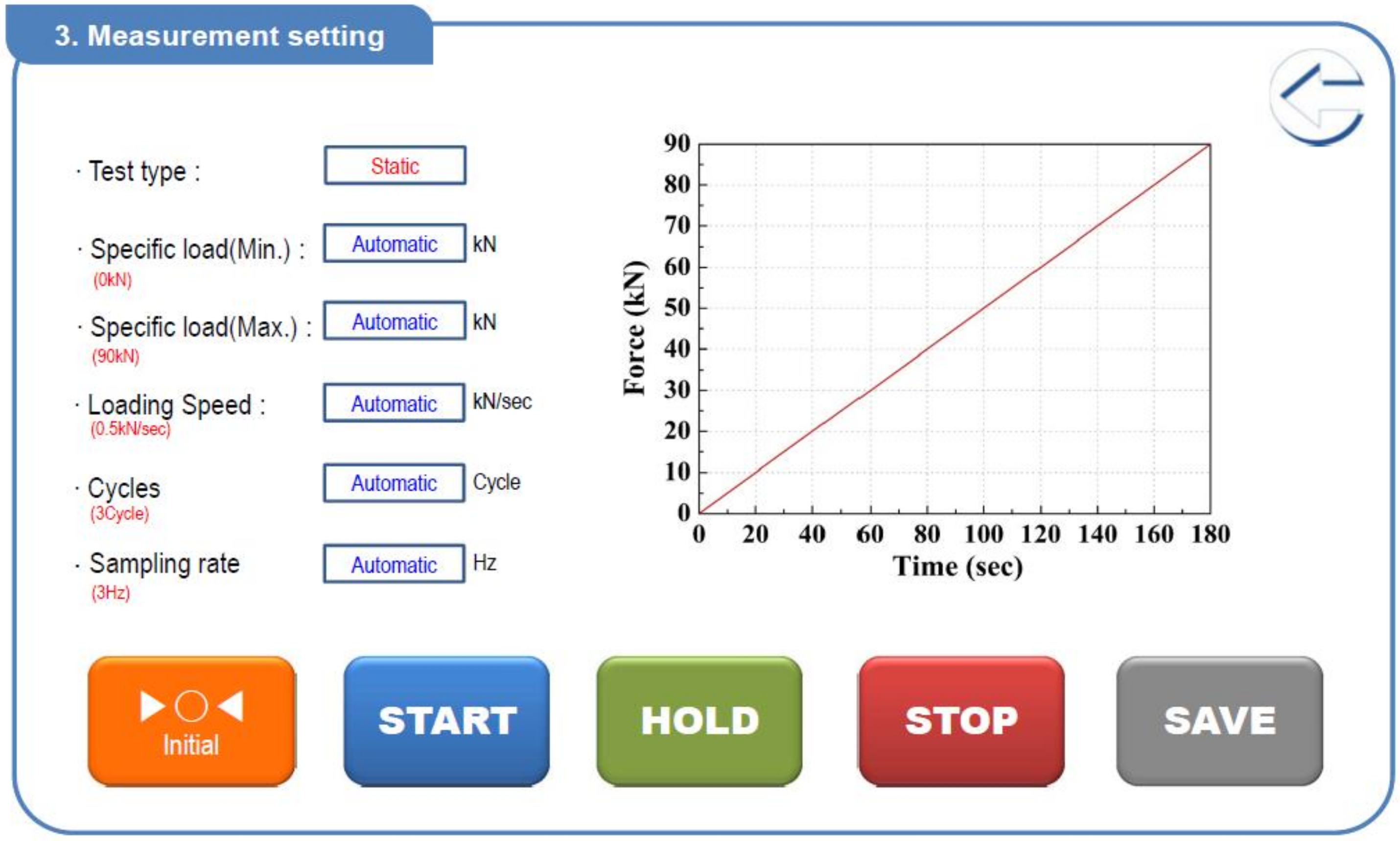
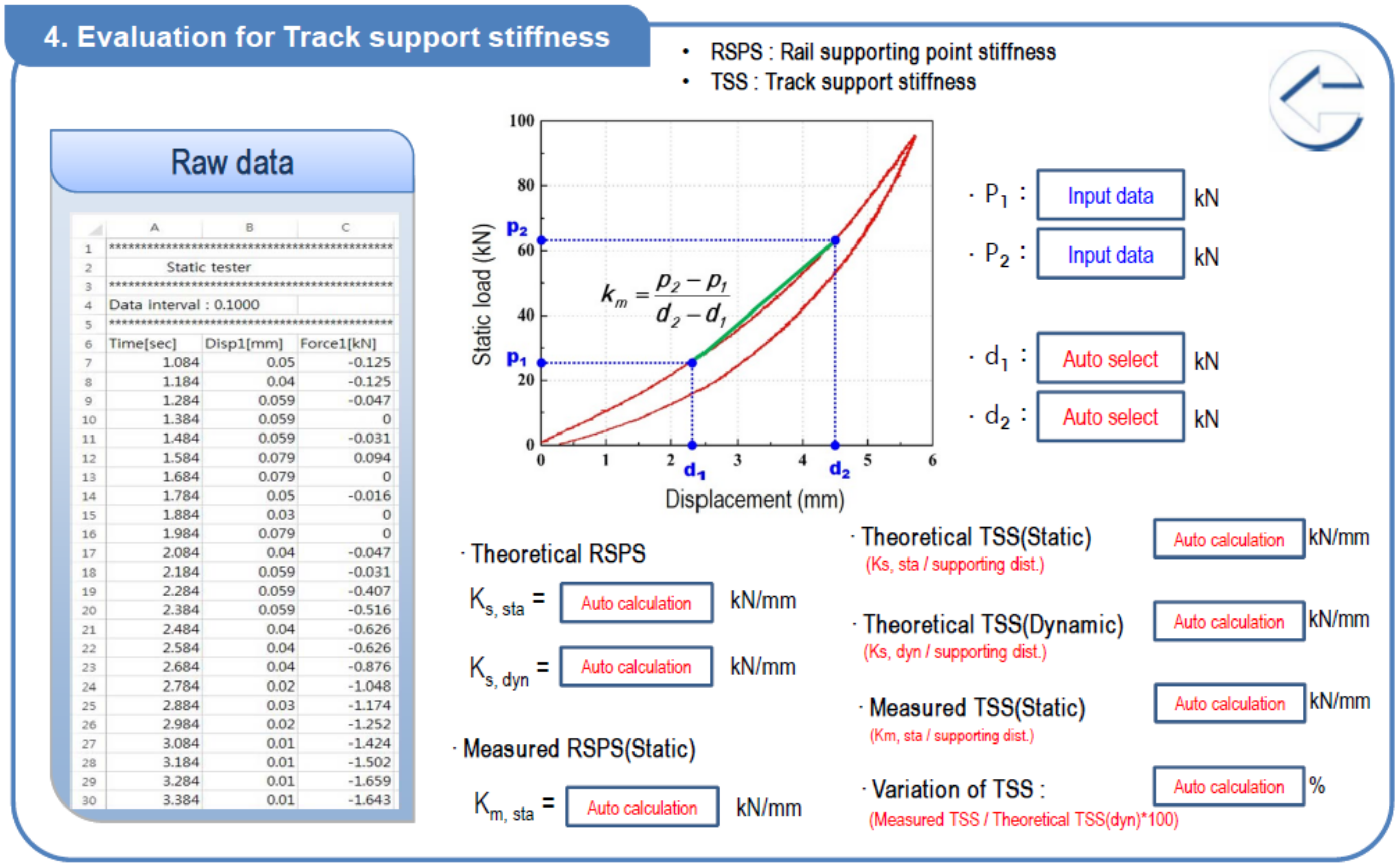
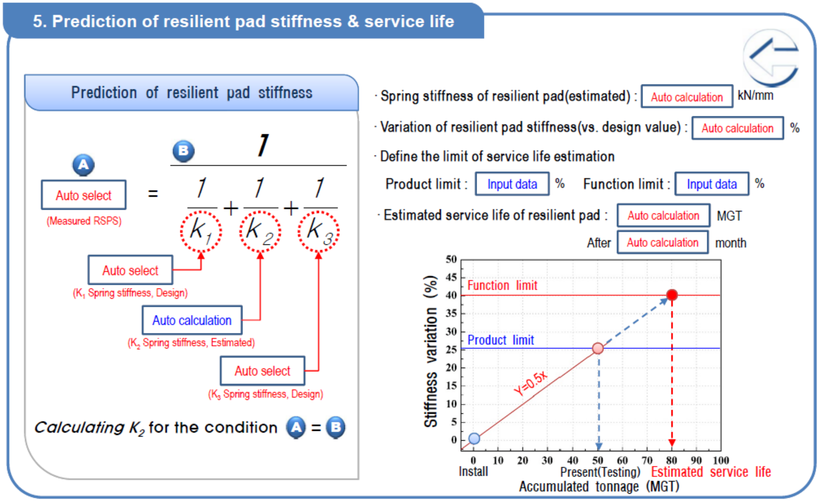
2.1. Operation Program for Measurement System

The software for operating the measurement system in this study was designed using wireless communication [18]. The software and measurement equipment communicate wirelessly, and the communication method (Modbus/TCP) is a communication protocol that is widely used worldwide for monitoring and controlling automation equipment [18]. The system for communication with the measurement system uses the Ethernet port of the control box installed in the equipment [18].
The Operation Program for Measurement System is a program that consists of the track support stiffness evaluation and a measurement system. The measurement system can output track performance test reports by inputting the tested track information (which can be entered in advance) of the test position by using the tablet PC, wirelessly and without any equipment, for the measurement and determination of the test load after mounting the measurement equipment on the field rail [2].
Figure 8 depicts a schematic of the test and evaluation program pertaining to the measurement system (S/W) [2]. Measurement settings that illustrate selection of the test type are depicted in Figure 9. The test types can be divided into static or dynamic tests [2]. If a static loading test is selected, the test load must be set along with the loading rate and the number of cycles. If the dynamic test is selected, the test load must be set along with the excitation frequency and the load repetition frequency [2].
The load model of the dynamic test can be implemented as a sine wave or triangular load, and the sampling frequency of the load and measured displacement data can be set up to 20 Hz. Furthermore, buttons for operating the instrument are displayed so that the sensors and actuators can be initialized and tested before commencing the test and paused during the test, or the test can be terminated entirely and saved. These operations can be implemented on the following display [2].
As shown in Figure 10, the aging level and track support stiffness of the elastic material can be evaluated. The displacement is automatically selected according to the loading data set by the user so that the spring stiffness, track support stiffness, and change rate of the rail supporting point stiffness can be analyzed by comparing its values with the design value, as shown in Figure 11 [2].

2.2. Performance Requirements of Track Support Stiffness Measurement System

The track support stiffness measurement system in this study is a TSS tester (Samlim Engineering. Co. Ltd., Seoul, Korea) used to measure the performance and durability of elastic materials for the slab track that can evaluate the state of track support stiffness by using the load–displacement curve at desired measuring points. The items that can be measured by using the track support stiffness measurement system are static and dynamic wheel loads and the displacement of rails or sleepers. Therefore, the static spring stiffness test is possible, using the static load and the displacement of the serviced track, and the dynamic spring stiffness test and dynamic characteristics analysis are possible using the dynamic load. In addition, the track support stiffness of the track structure can be evaluated by measuring the displacement of the track according to the static and dynamic loads. The core function of the TSS tester in this study is the loading function of the actuator. Therefore, in this study, the possibility of deriving the load–displacement curve for the tracks that are commonly used in the field by using the TSS tester, load control capability, and dynamic excitation capability of the test equipment is evaluated.

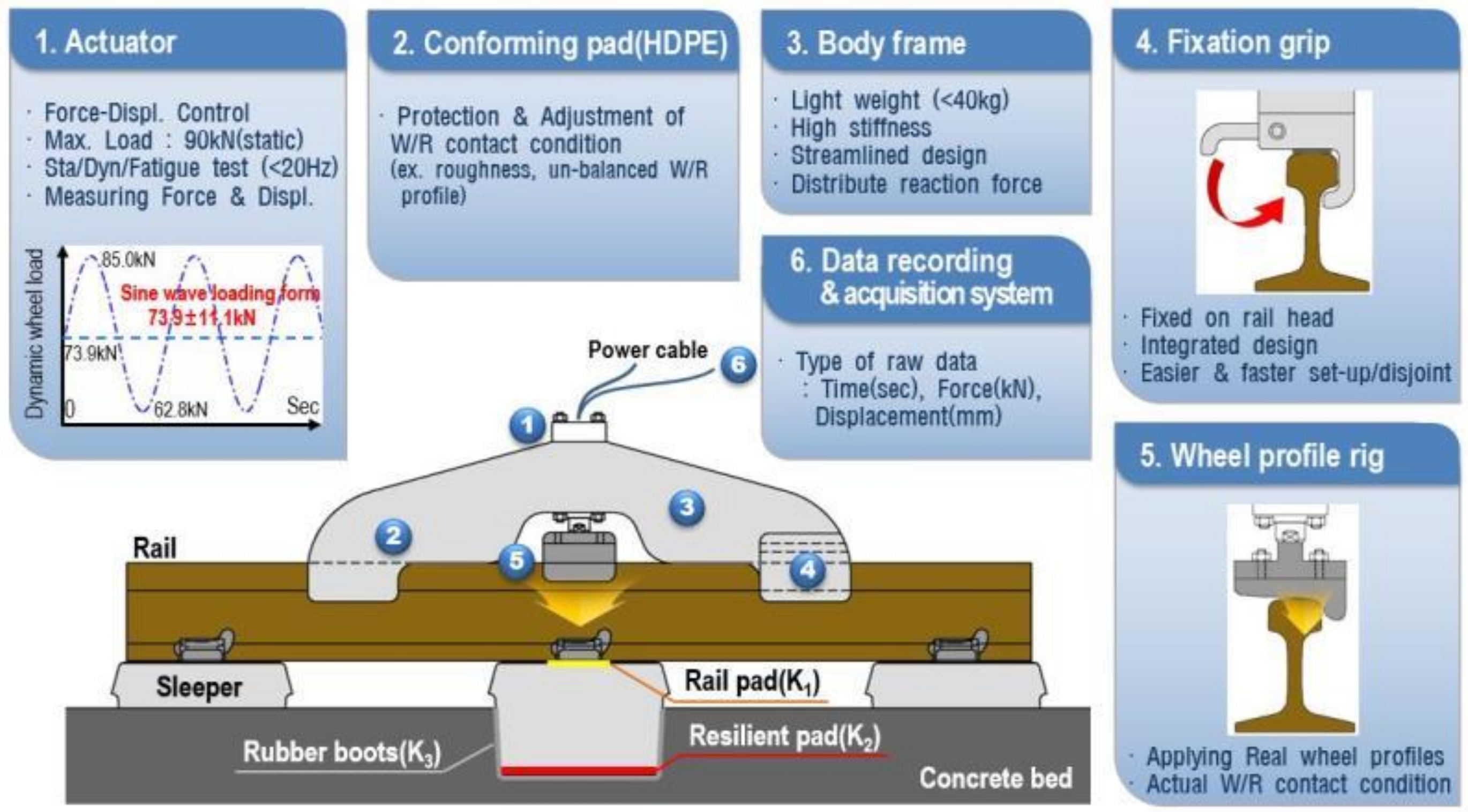
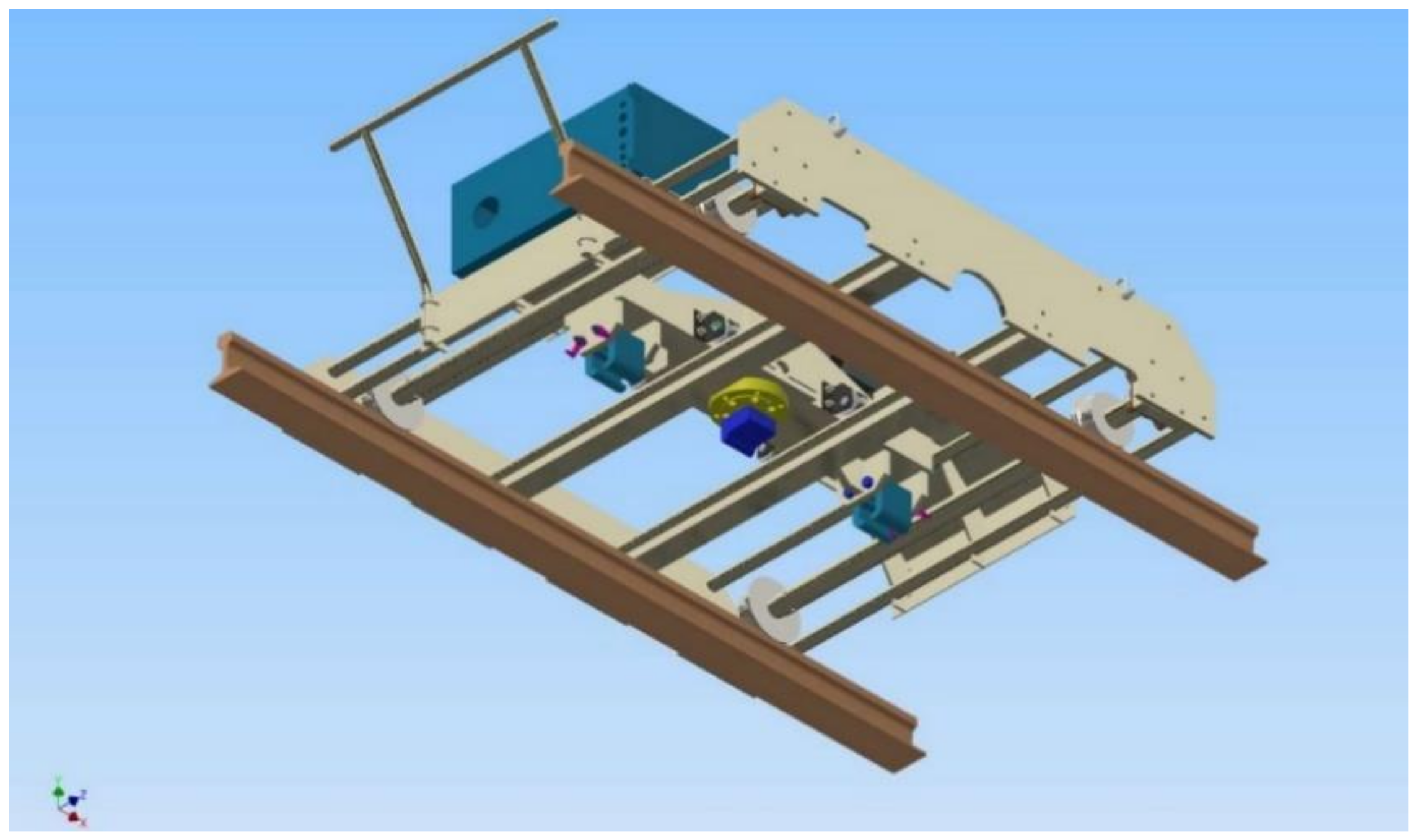
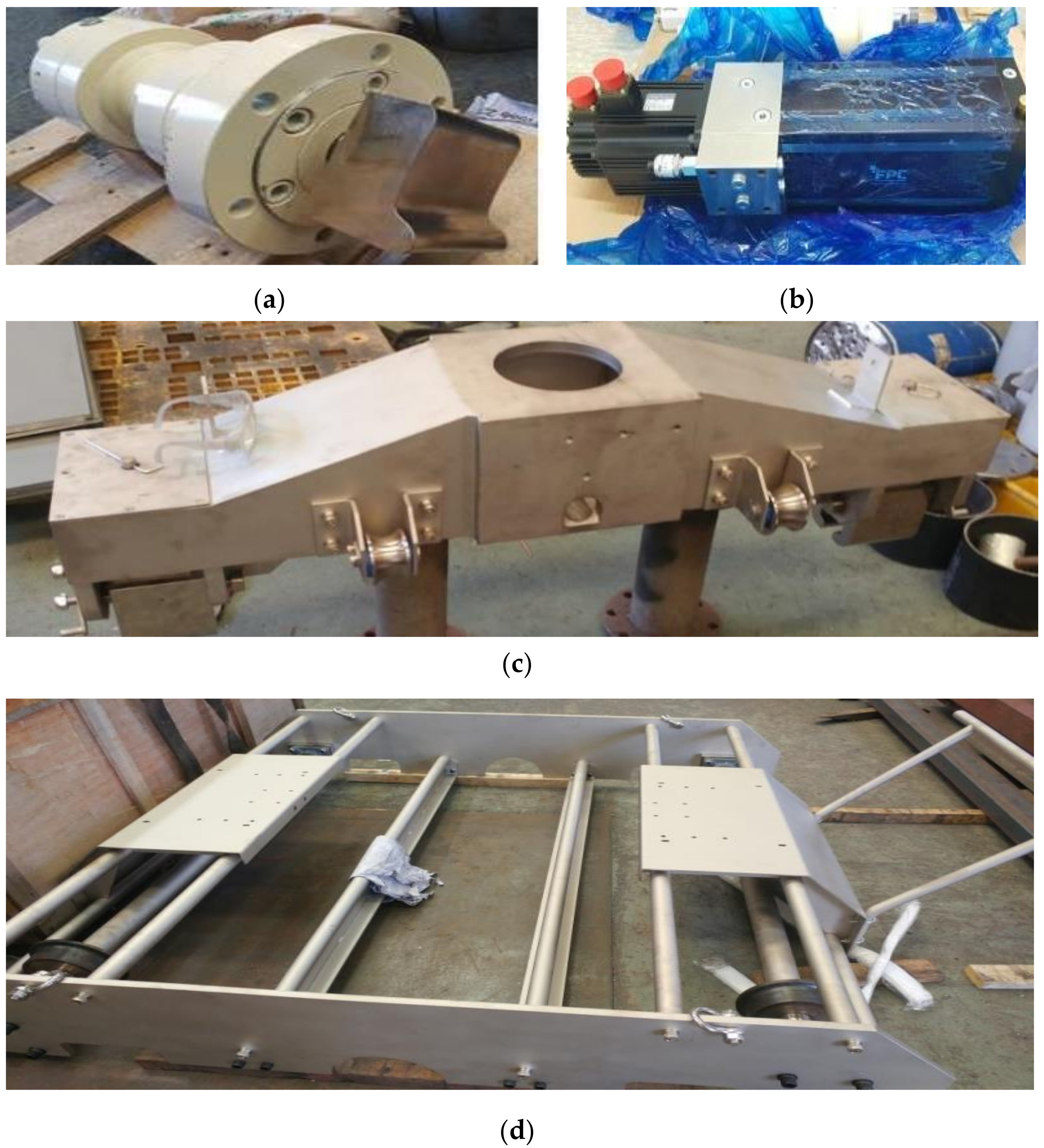
2.3. Development of Track Support Stiffness Measurement System
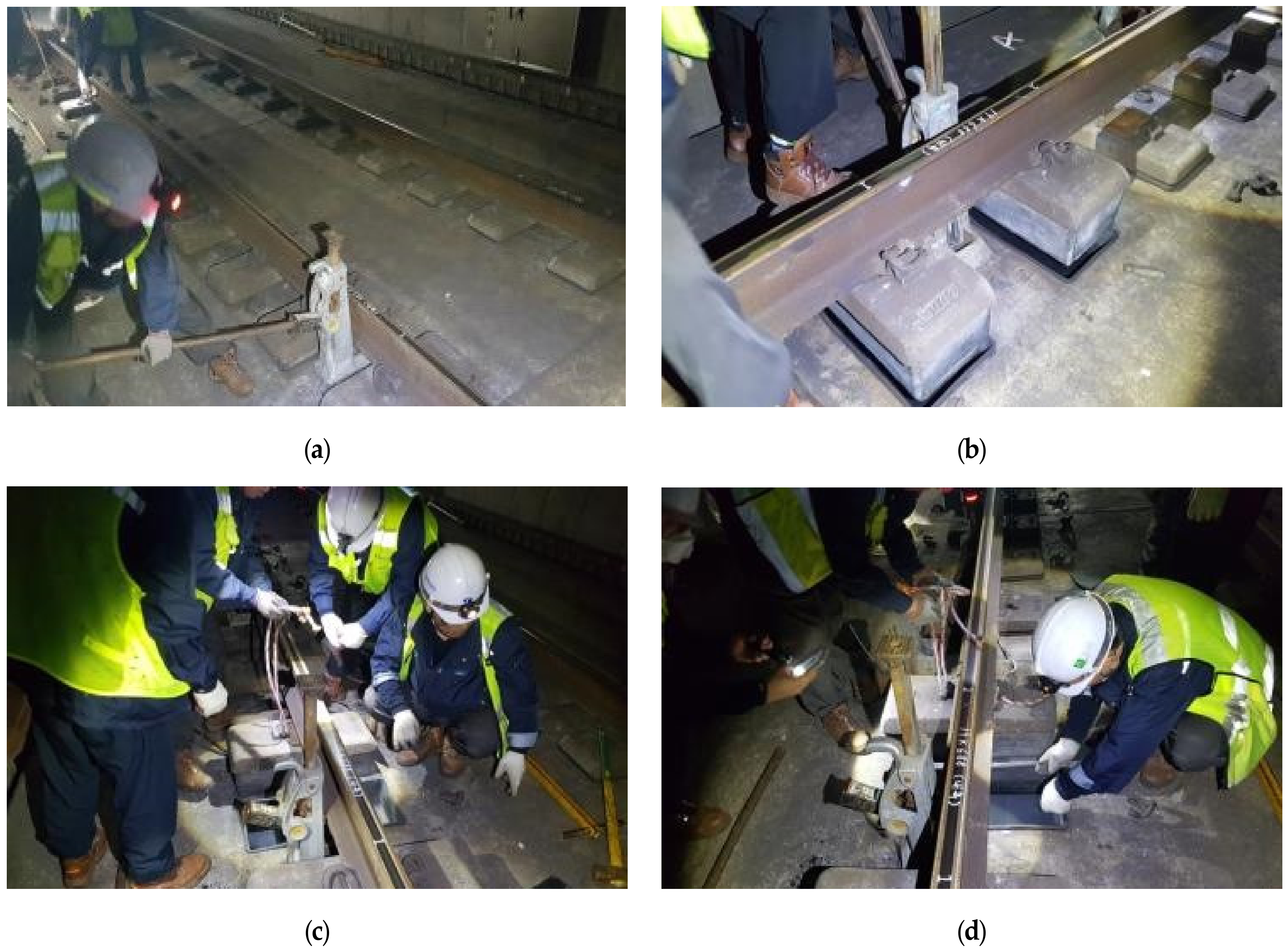
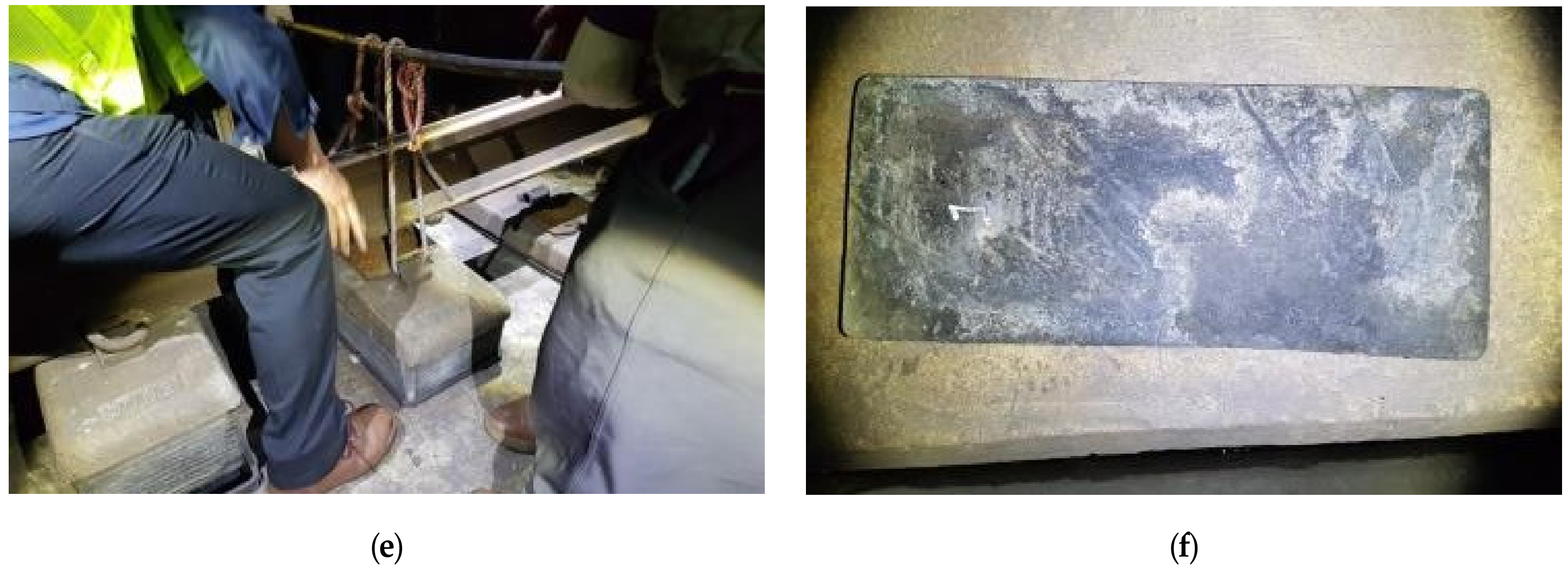
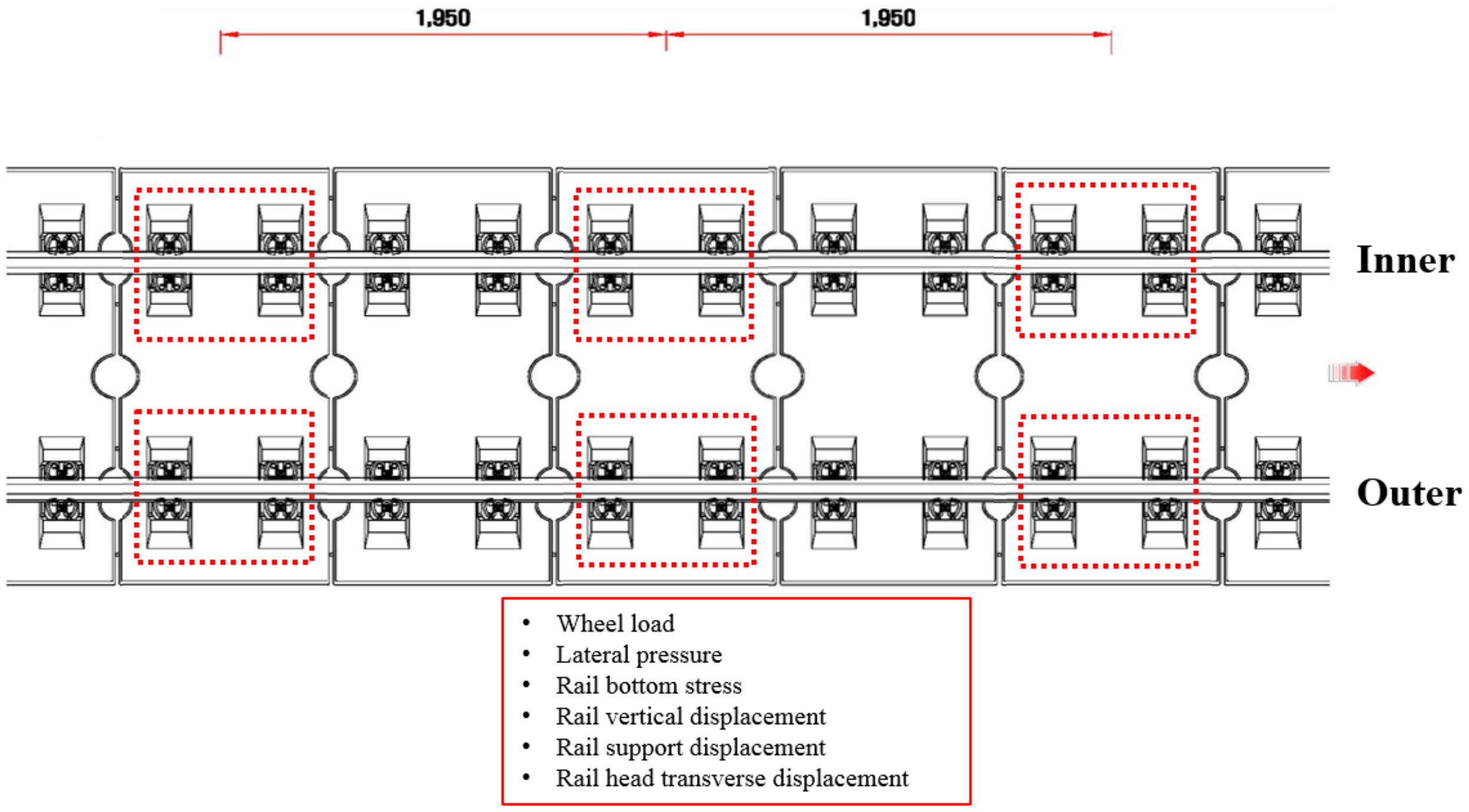
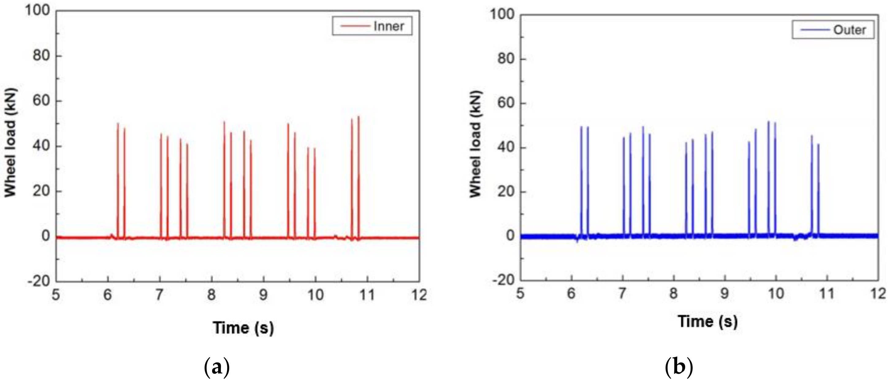
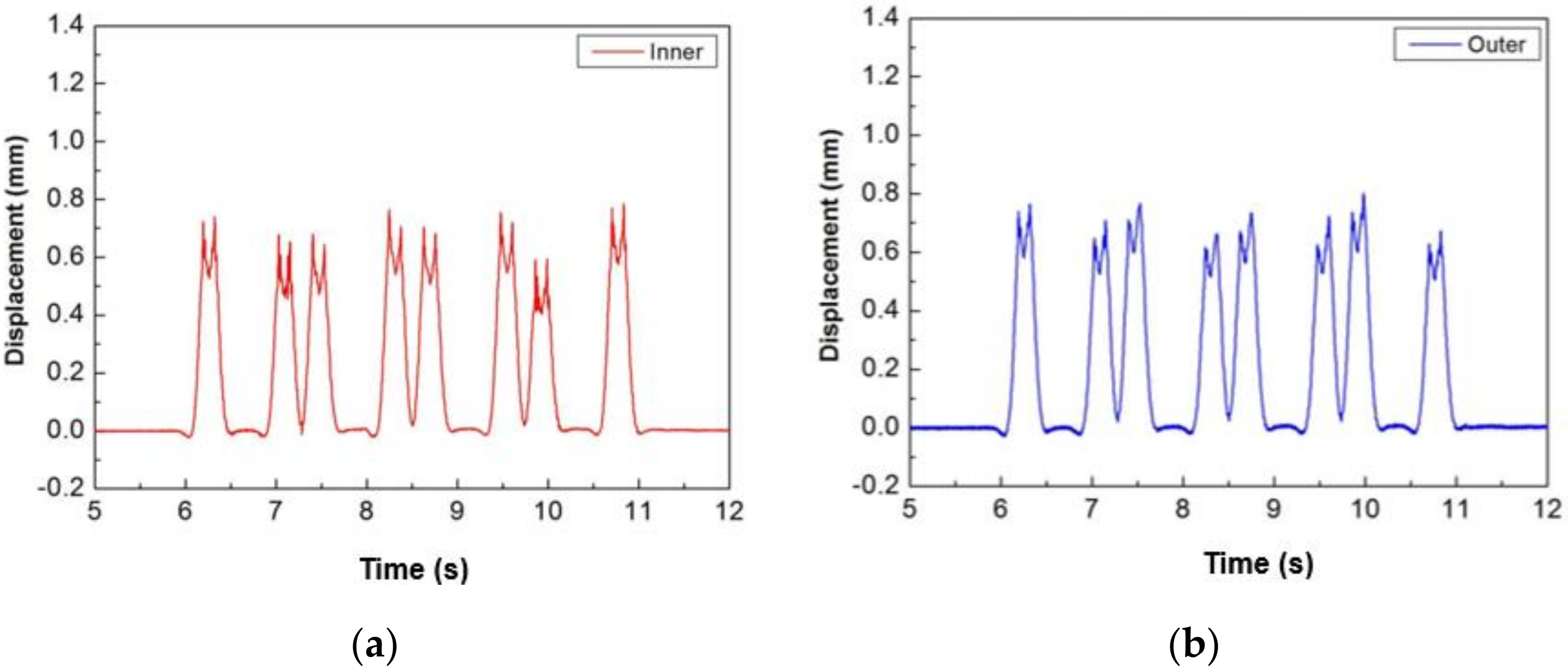
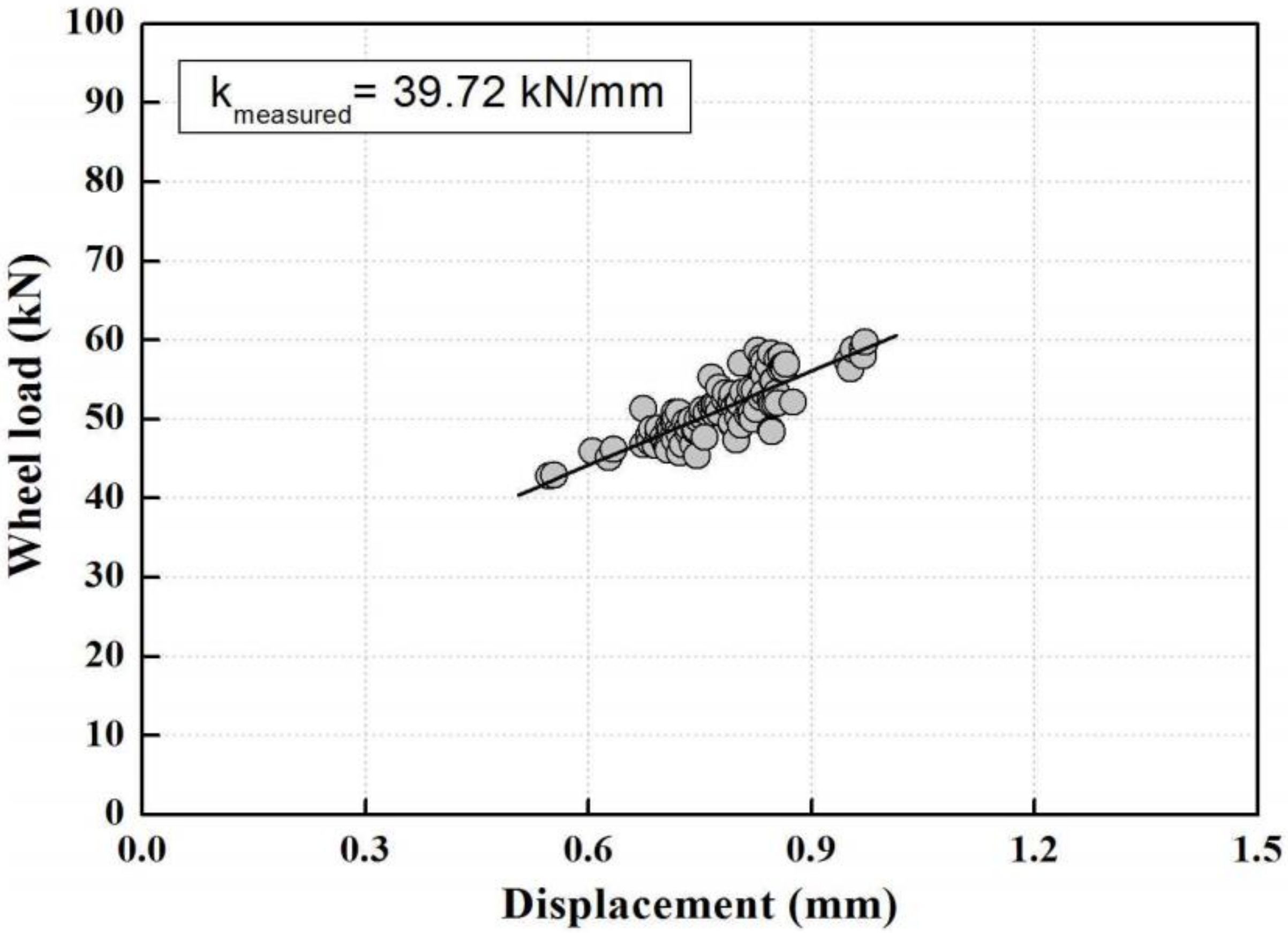
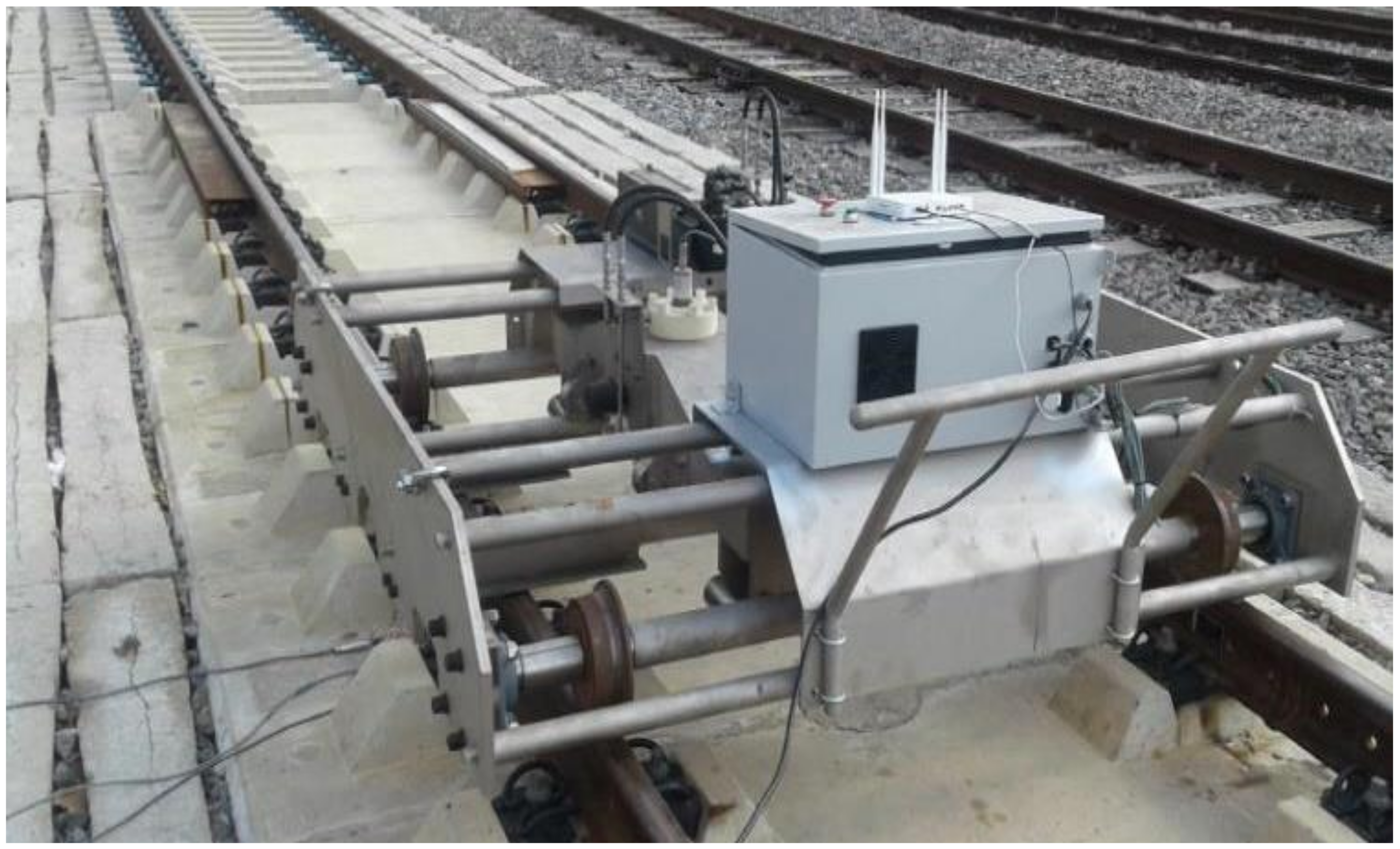
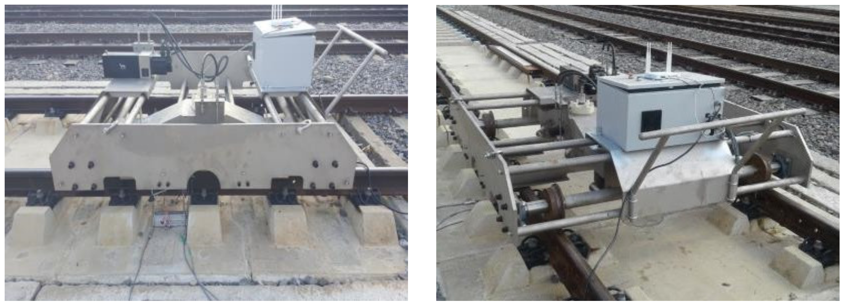
The basic structure of the track support stiffness measurement system (herein referred to as TSS tester) for slab tracks is composed of actuator and body frame, as shown in Figure 12 [2].
The core component of the TSS tester for slab tracks is the actuator that applies a load to the top part of the rail, as shown in Figure 12. This actuator can apply static and dynamic loads, and in the case of dynamic loads, the sine wave periodic load can be applied. Furthermore, the displacement response, according to the applied load, can be measured simultaneously so that the load–displacement curve can be obtained by measuring the load and the displacement simultaneously. In addition, a wheel-shaped jig connected with the actuator and the conforming pad on the rail face in the event of an uneven railhead was designed to eliminate the irregularity of load transfer and consider the real track in the field. The data storage device that controls the actuator of the measurement system and stores the measurement data signals can be controlled wirelessly, and the measurement data can be saved and handled by using the evaluation program (tablet PC) developed in this study without the need for separate configuration.
The mobile bogie frame with two wheel-sets consisting of a conical tread with a rigid axle was devised so that the measurement equipment, which is a heavy object, can be easily moved and operated in the real field, as shown in Figure 13. The bogie frame consists of a special coupling device that can integrate the loading TSS tester (actuator and body frameset) into the mobile bogie. [2]. The coupling device is designed to move the body frame and actuator, that is, the horizontal (simultaneous measurement of both the left and right rails) and vertical movements of the TSS tester.
Figure 14 shows the manufacturing view of the equipment accessories constituting the track support stiffness TSS tester [2]. The actuator with wheel rig (Figure 14a) that was the load–displacement measuring system was embedded in the center hole of body frame (Figure 14c). The body frame has two specially designed grip-type fixing points that can be fixed to the field rails an easily-removable pin in case of an emergency as is in a single system and, the frame comprises of a roller-type lateral movable fixing device for freely moving the left and right rails on the mobile bogie jig as shown in Figure 14c.
As shown in Figure 14d, the mobile bogie frame is composed of a hydraulic motor (Figure 14b) that applies hydraulic pressure to the actuator, a control box that controls the hydraulic pressure and communicates wirelessly with the tablet PC, and a mobile bogie that can be placed on all these devices and the body frame [1]. The TSS tester weighs lesser than 8.896 kN; however, only components depicted in Figure 14a–c are considered as loads, and the bogie frame (Figure 14d) is exempted from this consideration. Thus, the total load value equals less than 0.588 kN. The track support stiffness TSS tester in this study combined with the body frame part and the mobile bogie jig is as shown in Figure 15 [2].

Field Measurement

The track support stiffness measurement and evaluation system for the slab track was a test run in the field to test the operability of the TSS tester using the mobility and the program of the track support stiffness TSS tester. In addition, communication problems between the TSS tester and the evaluation program were identified, and issues that may occur in the field and their solutions were examined.
For the field test of the TSS tester, the adequacy of the TSS tester (load control ability, dynamic excitation ability, and loading rate) was evaluated, and the measurement accuracy (static and dynamic spring stiffness) was evaluated based on the measured data. Furthermore, the field test for performance evaluation of the TSS tester was conducted as an on-site test in the presence of an evaluator affiliated with an accredited test organization. The load control ability, dynamic excitation ability, and loading rates corresponding to the adequacy were evaluated according to the test standards laid out in the Korean Railroad Standard (KRS TR 0014-15 (R)) [11]. The field test view is shown in Figure 16 [2]. We measured one rail at a time, as shown in Figure 16. It is possible to apply pressure to each rail using an actuator. As described in Figure 16, while the TSS tester is operated, the operator must grasp the center of the handle bar and move.
The load was applied to the top surface of the rail through the wheel-shaped jig installed in the actuator. The loading test was performed by inputting static and dynamic loads, and the load and displacement measurement data acquired by the actuator sensor were collected remotely using a tablet PC. The maximum load was tested in the range of 1–68 kN considering the capacity of actuator and the Korean standard of the rail fastening system performance test (KRS TR 0014-15 (R)) [11]. The load waveform measured was shown in Figure 17 [2]. Load values in the 0–90 kN range could be applied. Accordingly, a 68-kN load was considered in this study based on KRS. The applied dynamic load was coupled with a positive load measuring at least 20 kN. Figure 18b describes the load–displacement result obtained for 5-Hz loading frequency, whereas Figure 17b describes a sinusoidal loading trend.
The static load modeled in this study is a linear increase function that maintains a constant loading rate from the initial load to the maximum load and checks whether the load is applied to the maximum load without loss or variation of the load through this field test. As a result of the analysis, in the repeated test condition by three times (three cycles), as shown in Figure 18a, a constant slope was obtained from the initial load to the maximum load. A linear load–time history function was implemented at a constant speed (68 kN load = 116.57 kN/min for 35 s) without any change in load. Therefore, it was experimentally proven that the system could satisfy the loading rate of the TSS tester specified in KRS TR 0014-15R (120 ± 10 kN/min) [11].
The dynamic load history waveform, modeled by a sine function with an excitation frequency of 5 Hz, as shown in the dynamic test results in Figure 18b, is communicated remotely using a tablet PC during three cycles. The uniformity of the signals was experimentally verified. Accordingly, it was analyzed that the hysteresis function of the constant sinusoidal waveform could be realized without any loss of load or change of loading rate.
The relationship between the load exerted on the track by the test load, and the resulting elastic displacement of the track was analyzed by the load–displacement curve. When rails are loaded using a TSS tester, the load is transferred to individual track components. The TSS can measure data to fit the load–displacement curve depicted in Figure 18b via application of the dynamic load patter depicted in Figure 17b. Accordingly, the track support stiffness of the target track can be evaluated and elastic materials and spring stiffness can be inferred. The dynamic load–displacement curve obtained through the dynamic excitation test and the dynamic damping performance of the track structure can be evaluated by comparing the loop area of the load–displacement curve in the form of a loop.
As shown in Figure 18a, the slope of the static load–displacement curve calculated, based on the static test result, is relatively constant during the three cycles and is obtained through the TSS tester. Accuracies of the load–displacement measurement result and load control of the TSS tester have been experimentally demonstrated in this study.
As shown in Figure 18b, the dynamic spring stiffness using the slope of the dynamic load–displacement curve obtained through the dynamic excitation test can achieve a relatively constant slope over three cycles. As a result, the loop area of the load–displacement curve was also similar over three cycles, and the excitation force of the sine wave and the response rate of the displacement response were also analyzed.
Table 1 shows the results of estimating and comparing the track support stiffness and spring stiffness of the resilience pad by using the testing methods such as the TSS tester of this study, conventional field test and design specification. The measured track support stiffness was compared with the design standard value, and the result confirmed that the track support stiffness measured by the TSS tester was within the 5% range. Therefore, it was found that the performance of elastic materials can be inferred using the TSS tester of this study even if the resilience pad sample is not collected through the nightly separate track work in the field and conventional field test using actual vehicles on a service time.

3. Results and Discussion

In this study, field tests were conducted to evaluate the performance of the TSS tester for the slab track and to evaluate the adequacy of the developed system and to evaluate the satisfaction of the performance requirements of the measurement and evaluation system. The performance requirement of the TSS tester is the appropriateness of the functional performance of the test equipment. For this evaluation, whether or not the system satisfies the test standards of railway standards (KRS TR 0014-15R) [11] for load control capability, dynamic excitation ability, and loading rate was examined. Furthermore, regarding the evaluation program that controls the test equipment as well as acquires, saves and post-processes measurement results, it was verified based on the operating performance of the test equipment. This was achieved using wireless communication if the control performance that met the normal operation and performance requirements of the test equipment was implemented.
The main requirement of the track support stiffness evaluation system proposed in this study is the precision of the measurement to evaluate the static and dynamic spring stiffness based on the simultaneous measurement of the load and displacement. As a result, the relative error range of static and dynamic spring stiffness obtained by the TSS tester through wireless communication is analyzed to be less than 3% of the average value of the measuring result, which proved the adequacy of the control performance aspect of the TSS tester.
Among the main performance indicators set in this study, the adequacy of the TSS tester (load control capability, dynamic vibration capability, and loading rate) is the control precision of static and dynamic test loads and the excitation frequency implementation of the loading rate and dynamic excitation load (which as a sine function). In addition, a static load corresponds to a linearly increasing function that maintains a constant loading rate between the initial and maximum load values. This can be verified via field tests performed in this study to substantiate the adequacy of the load–history function. In most performance tests of elastic materials for the slab track, the static and dynamic spring stiffness of rail fastening system, which are obtained through laboratory tests, are generally tested only for resilient pads. In addition, even in the assembly test considering the rails and sleepers, the test specimen is very stable in terms of installation conditions, and the length of the rail applied to the assembly test is also short. On the other hand, in the field test results, various variables (e.g., rail surface irregularities, track slopes, sleepers and bedding conditions) and longitudinal and lateral load distribution effects distributed through rails, are included. Given that this cannot be reflected, the margin of error for the measurement results obtained in the real field track performed in this study is less than 3% overall, which is reliable in terms of measurement accuracy. Furthermore, when the measurement result of the system was compared with the design reference value, the difference was less than 5%. Therefore, it was concluded that the TSS tester and control program of this study present no problems with respect to their application in the field as track support stiffness evaluation systems that can replace indoor tests.

4. Conclusions

In this study, we developed a track support stiffness measurement system and software that can control the test equipment and save, analyze, and evaluate the measurement results. We also evaluated the performance of the developed system and adequacy in terms of field applicability. The results are as follows.
(1)
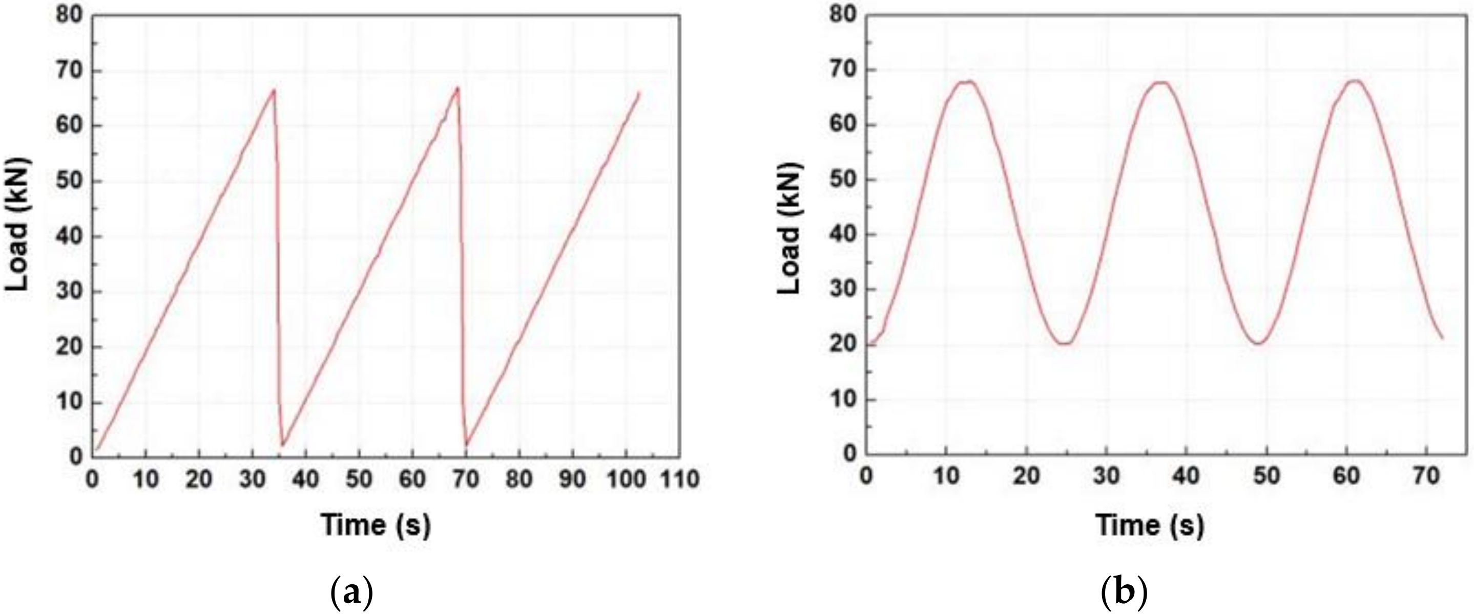
The field test results proved the adequacy of static and dynamic spring stiffness evaluation results, and the adequacy of the test equipment (load control capacity, dynamic vibration capacity, and loading rate), which are the performance requirements of the development system, and are also related to the relevant test standards and evaluation method. Among the main performance requirements set in this study, the adequacy of the TSS tester (load control capability, dynamic vibration capability, and loading rate) is the realization of the excitation frequency of the static and dynamic excitation loads with the control accuracy of the static and dynamic test loads.
(2)
The evaluation system in this study reflects the field conditions and can be directly tested on operational tracks to analyze and compare the results at various test points. In addition, the error range of the field test results was analyzed to be less than 3% in both the static and dynamic test results, indicating a reliable level in terms of measurement accuracy. Furthermore, the error of the dynamic test result of the track support stiffness measured by the design standard value and test equipment was less than 5%. Therefore, it was concluded that the track support stiffness measurement system and its evaluation program of this study can be used to predict the spring stiffness of resilience pad in the real field and should be of practical use in track maintenance.
(3)
In continuation of this research, the authors intend to perform further experiments under different field conditions.

Author Contributions

Conceptualization, J.-Y.C. and J.-S.C.; investigation, J.-Y.C.; data curation, J.-S.C. and J.-Y.C.; resources, M.-H.K.; writing—original draft preparation, J.-Y.C. and S.-H.K.; writing—review and editing, S.-H.K. All authors have read and agreed to the published version of the manuscript.

Funding

This research received no external funding.

Acknowledgments

This Work was supported by the Technology Development Program (S2463949) funded by the Ministry of SMEs and Startups (MSS, Korea).

Conflicts of Interest

The authors declare no conflict of interest.

References

  1. Choi, J.Y. Qualitative Analysis for Dynamic Behavior of Railway Ballasted Track. Ph.D. Thesis, Technical University of Berlin, Berlin, Germany, 2014. [Google Scholar]
  2. Kim, M. A Study on Evaluation System of Track Support Stiffness for Concrete Tracks. Ph.D. Thesis, Dongyang University, Yeongju-si, Korea, 2020. [Google Scholar]
  3. Choi, J.Y.; Kim, S.H. Impact Evaluation of Track Girder Bearing on Yeongjong Grand Bridge. Appl. Sci. 2020, 10, 68. [Google Scholar] [CrossRef] [Green Version]
  4. Choi, J.Y.; Lee, K.Y.; Chung, J.S.; Kim, S.H. Rail Pad Corrosion Effects on the Dynamic Behavior of Direct Fixation Track Systems in Marine Environments. Appl. Sci. 2020, 10, 2245. [Google Scholar] [CrossRef] [Green Version]
  5. Choi, J.Y.; Gong, H.S.; Kim, J.H.; Kim, H.S.; Chung, J.S. An Experimental Study on Causes Evaluation of Rail Corrugation for Concrete Track (STEDEF) in Urban Transit. J. Converg. Cult. Technol. 2018, 4, 413–418. [Google Scholar]
  6. Barlow, S.C. Field Measurements of Slab Track Vibration to Demonstrate the Insertion Loss of Low Stiffness Rail Fasteners. In Proceedings of the ACOUSTICS 2004, Gold Coast, Australia, 3–5 November 2004; pp. 23–30. [Google Scholar]
  7. Mueller-Boruttau, F.; Breitsamter, N. Elastic Elements Reduce Vibration Emission Some Thoughts on Insertion Loss. In Proceedings of the EURODYN 2005, Paris, France, 4–7 September 2005. [Google Scholar]
  8. Kaewunruen, S.; Remennikov, A.M. State Dependent Properties of Rail Pads. Transp. Eng. Aust. 2009, 11, 1–8. [Google Scholar]
  9. Carrascal, I.A.; Casado, J.A.; Polanco, J.A.; Gutiérrez-Solana, F. Dynamic Behaviour of Railway Fastening Setting Pads. Eng. Fail. Anal. 2007, 14, 364–373. [Google Scholar] [CrossRef]
  10. Mars, W.V.; Fatemi, A. Factors that Affect the Fatigue Life of Rubber: A Literature Survey. J. Rubber Chem. Technol. 2004, 77, 391–412. [Google Scholar] [CrossRef]
  11. KRS TR 0014-15R, Rail Fastening System, Korean Railway Standards. Available online: http://www.kric.go.kr (accessed on 28 May 2015).
  12. Shimada, S.; Anderson, D.C. Testing the dynamic properties of resilient track components at frequencies critical to noise and vibration performance. In Proceedings of the ACOUSTICS 2004, Gold Coast, Australia, 3–5 November 2004; pp. 17–22. [Google Scholar]
  13. Thompson, D.J.; Verheij, J.W. The dynamic behaviour of rail fasteners at high frequencies. Appl. Acoust. 1997, 52, 1–17. [Google Scholar] [CrossRef] [Green Version]
  14. Heunis, J.J. Material Models for Rail Pads. Master’s Thesis, University of Stellenbosch, Stellenbosch, South Africa, 2011. [Google Scholar]
  15. Choi, J.Y.; Kim, H.S.; Han, K.S.; Jang, C.J.; Chung, J.S. Damage Evaluation of Track Components for Sleeper Floating Track System in Urban Transit. J. Converg. Cult. Technol. 2019, 5, 387–394. [Google Scholar]
  16. Degrande, G.; Schillemans, L. Free field vibrations during the passage of a Thalys high-speed train at variable speed. J. Sound Vib. 2001, 247, 131–144. [Google Scholar] [CrossRef] [Green Version]
  17. Kogut, J.P.; Lombaert, G.; François, S.; Degrande, G.; Haegeman, W.; Karl, L. High speed train induced vibrations: In situ measurements and numerical modelling. In Proceedings of the Tenth International Congress on Sound and Vibration 2003, Stockholm, Sweden, 7–10 July 2003. [Google Scholar]
  18. SOLLAE System, ezTCP of Modbus/TCP. Available online: http://www.sollae.co.kr (accessed on 20 February 2020).
Figure 1. Slab-track system.
Applsci 10 04344 g001
Figure 2. Photograph of collecting for used resilience pad samples. (a) Pre-work (Dismantling rail fastener and installation Jack-up device); (b) Lifting sleeper (RC block); (c) Positioning and separating sleeper and rubber boot; (d) Replacement and insertion of resilience pad; (e) Put the sleeper down; (f) Used resilience pad sample.
Applsci 10 04344 g002aApplsci 10 04344 g002b
Figure 3. Location of sensor installation.
Applsci 10 04344 g003
Figure 4. Photograph of typical field measurement on track.
Applsci 10 04344 g004
Figure 5. Examples of measured dynamic wheel load. (a) Inner rail; (b) Outer rail.
Applsci 10 04344 g005
Figure 6. Examples of measured dynamic rail displacement. (a) Inner rail; (b) Outer rail.
Applsci 10 04344 g006
Figure 7. Measured track support stiffness by the conventional field measurement.
Applsci 10 04344 g007
Figure 8. Schematics of test and evaluation program for measurement system (S/W).
Applsci 10 04344 g008
Figure 9. Setting of test conditions.
Applsci 10 04344 g009
Figure 10. Example of the test result for the load–displacement curve.
Applsci 10 04344 g010
Figure 11. Evaluation of track support stiffness.
Applsci 10 04344 g011
Figure 12. Schematic of track support stiffness (TSS) tester components.
Applsci 10 04344 g012
Figure 13. Modeling of the TSS tester.
Applsci 10 04344 g013
Figure 14. Photograph of TSS tester components. (a) Actuator and wheel jig; (b) Hydraulic motor; (c) Body frame; (d) Bogie frame.
Applsci 10 04344 g014
Figure 15. Photograph of the TSS tester.
Applsci 10 04344 g015
Figure 16. Photograph of field measurement.
Applsci 10 04344 g016
Figure 17. Measured results of static and dynamic loads (sample). (a) Static load; (b) Dynamic load.
Applsci 10 04344 g017
Figure 18. Measured results of the load–displacement curve. (a) Static; (b) Dynamic.
Applsci 10 04344 g018
Table 1. Comparisons of measured track support stiffness and predicted spring stiffness of resilient pad by testing methods.
Measured Results Using TSS TesterConventional
Field Test Using Actual Vehicle
Design Value (Korean Standard)
Test CycleStaticDynamic
A*BA*BA*CD*C
1st15.4334.87(−)2.0917.1038.41(−)0.2317.7239.72(−)3.5017.5 (±2.5)40.24(−)4.79
2nd16.1736.45(+)2.6016.9838.16(−)0.93(−)4.18(−)5.47
3rd15.6835.42(−)0.5117.3538.94(+)1.23(−)2.09(−)3.36
Ave.15.7635.580.0017.1438.50(+)0.07(−)3.27(−)4.56
* : Track support stiffness (kN/mm). A: Predicted spring stiffness (kN/mm). B: Relative error vs. average (%). C: Relative error vs. B (%). D: Design static spring stiffness (kN/mm).

