1. Introduction
The terms “process manufacturing industry” or “process industry” usually refer to the industrial sector, which transform primary raw materials into products that might afterwards be further processed and transformed by other industries in order to deliver complex assembled products [
1]. It includes, for instance, the metallurgical, chemical, glass, pulp and paper and food industries. Each manufacturing process contains several steps, starting from storage, transportation and preparation of primary raw materials, melting and/or transformation into chemical reactors, refining, shaping (e.g., casting, hot and cold rolling) and eventually, coating. All these sub-processes are closely correlated and often seamlessly connected. In effect, many of these production cycles are at least partly continuous, i.e., the production runs 24/7.
During the different stages, unexpected events may happen causing e.g., delays, waste of materials and off-spec products, thus, the overall engineering system must rapidly and efficiently react in order to mitigate the effects of such events. With the paradigm of Industry 4.0, all the industrial sectors are keen to implement the concept of a “smart factory”, that is a context-sensitive manufacturing environment that can handle turbulences in real-time production using decentralized information and communication structures for an optimum management of production processes [
2].
A paradigm very suited for addressing smart and distributed systems acting in complex and dynamic environments like process industries is the agent-based approach. A Multi-Agent System (MAS) consists of several computational entities capable of independent actions, called agents, which communicate with each other, and have the ability to cooperate, coordinate, and negotiate [
3]. The research on agent-based approaches continues to provide technological solutions in a wide variety of domains [
4], especially the use of agent abstraction for modeling and simulating systems. In reference [
5], for instance, a multi-agent simulation was used to evaluate the traders’ behavior in perishable goods markets under several market conditions, whereas an agent-based model for the management of traffic flows in a network under distinctive congestion scenarios was presented in reference [
6].
Concerning manufacturing applications, the potential of MAS is very promising and the agent-based paradigm for modeling and simulation has receiving ever increasing attention during the last two decades. The leading role of MAS as fundamental technology for industrial production management and optimization in light of current and future developments of the digitalization of industrial production cycles is highlighted in reference [
7]. A survey of agent applications in the manufacturing domain, ranging from engineering design to life-cycle management, was presented in reference [
8], whereas a discussion of the advantages of using agent-based modeling tools to support the development of agent-based manufacturing control systems was presented in reference [
9]. In reference [
10], agent-based modeling and simulation were used for the design and verification of an automatic manufacturing execution system with the aim of evaluating emerging behaviors and macroscopic dynamics in a multiproduct batch plant. An agent-based assembly system simulation was presented in reference [
11] that shows how agents handle a production plan dynamically using communication and negotiation. In reference [
12], one of the first examples of application of MAS in the steel sector was proposed, which targets the dynamic reallocation of products. MAS were also successfully applied in electric steelworks for dynamic energy management [
13,
14]. More recently, in reference [
15], an on-line and distributed scheduling system based on multi-agent systems was proposed in order to manage both the scheduling of machines and the automated guided vehicles of a manufacturing system. A MAS approach for modeling and self-optimizing the production of flat steel products was presented in reference [
16], where the decentralized optimization of the production scheduling is carried out by intelligent agents exploiting product and process knowledge. An exemplar application of MAS in the chemical sector for production scheduling optimization is provided in reference [
17]. An interesting review on the application of MAS for complex networks management in the context of process systems engineering is provided in reference [
18].
This paper proposes an event-driven agent-based model for simulating the operations of an industrial process subject to unexpected and uncertain events, such as faults, off-spec productions, and overloading of the production lines. In order to handle unforeseen events, a combination of reactive agents and a communication mechanism for timely information dissemination were adopted. Differently from most of existing models, the proposed tool targets the specific needs of the process industry and combines the potential and the flexibility of the agent-based approach with usability and practicality in order to facilitate its deployment and customization to different production chains which are typically found e.g., in the metallurgical sector.
The paper is organized as follows:
Section 2 describes a generic industrial process used as prototype of the application.
Section 3 presents the agent-based model with the main actors involved in the system. A summary of the interactions among agents and the used communication mechanism are also presented here. The software architecture is presented in
Section 4, while simulation results and discussions are presented in
Section 5. Finally, the conclusions are given in
Section 6.
2. Process Model
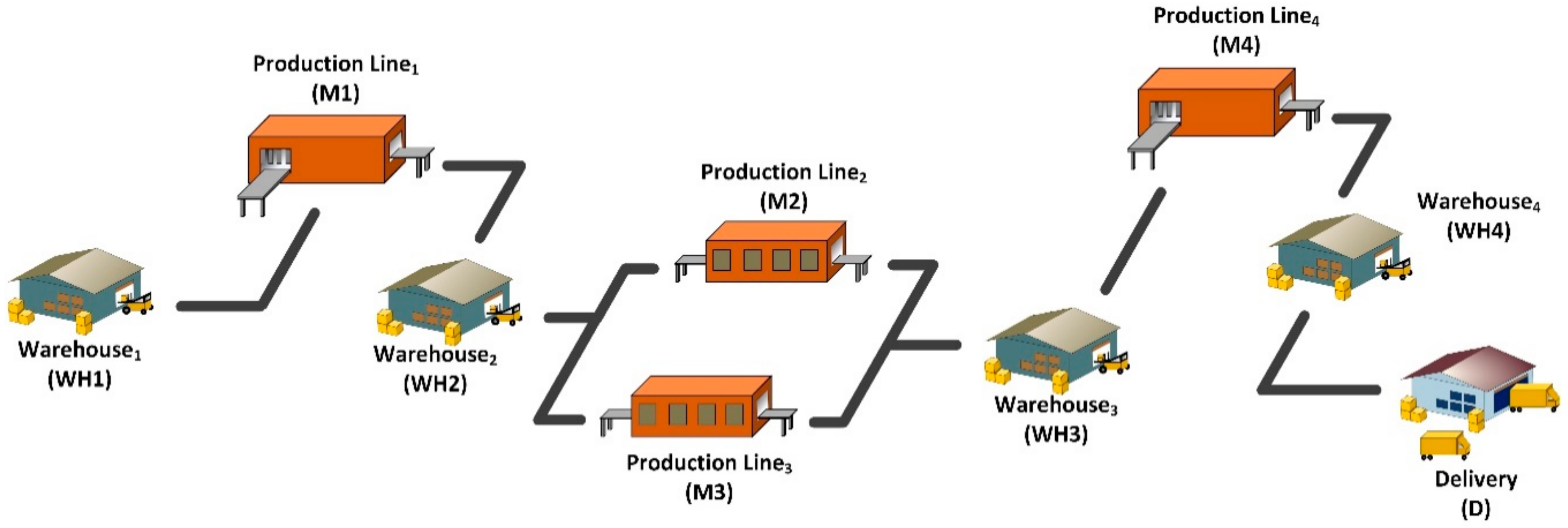
The industrial process model described in the present paper must be considered as a generic continuous process belonging to any industrial sector. A raw or semi-manufactured product must be further processed by several production lines in order to be sent to the market as a finished product. The production lines are organized in series, one after the other. These series represent the considered production process steps. Sometimes, one production step is developed by several equivalent production lines connected in parallel, i.e., performing the same working operations, namely, a product might be worked by any of these lines. For each production step, the plant provides a warehouse where products are stored before being worked. The above-described generic production process is schematically depicted in
Figure 1.
The exemplar production site depicted in
Figure 1 is composed of three production steps, four production lines (two of them are equivalent) and four warehouses. The last step concerns the packaging and the products’ delivery. Each warehouse has a limited storage capacity. A product might be moved inside a warehouse before being processed by a production line. Each production line is composed of different machines, each one with a limited buffer that represents the queue of the machine. In the current model, it is assumed that each production line is composed, at most, by one machine with a buffer maximum capacity of two products. A product, in order to be accepted and processed by a machine, needs firstly to be added to its production scheduling. This operation is usually performed at the beginning of the process, i.e., when the production scheduling is defined according to the production orders information, the available input materials, and the status of each machine. Nevertheless, the scheduling of a machine can change over time due to unexpected events such as faults, maintenance operations or machine overloading. Once the product has been accepted, it must be loaded into the machine’s buffer, and then, it is ready to be worked. When the production line finishes processing the semi-finished product, it will be transported into the next warehouse and this scheme is repeated until the product reaches the delivery zone, where the product is loaded on a truck and shipped. In summary, a product undergoes the following steps during the process chain:
- A.
Assigning the product to a machine’s scheduling.
- B.
Moving the product within a warehouse.
- C.
Loading the product into a machine’s buffer.
- D.
Working the product on a machine.
- E.
Stocking the product into a warehouse after processing.
- F.
<Repeat phases C, D and E until the last warehouse is reached>
- G.
Loading the product to a truck to be shipped.
- H.
Delivering the product.
As an example,
Table 1 shows all the operations of the production process schematically depicted in
Figure 1, together with the affected processes and the corresponding code assigned to the operations. In the depicted exemplar case, only six main operations were defined, but it is clearly possible to extend the number of operations by adding new and specific ones.
3. Agent-Based Model
The overall aim of the developed MAS is to support and facilitate the transformation of traditional process systems, following the scheme reported in
Figure 1, into smart factories, which are capable of handling real-time unexpected changes of the production by exploiting communication and intelligent behaviors. The following objectives were considered:
To transform the product into an intelligent module, able to store and handle its state with updated real-time information.
To exchange information between machines, products, warehouses, and the other actors of the system.
To provide intelligent routing of the products by optimizing the use of the production machines and maintaining high levels of product quality.
To automatically reallocate products that lose compliancy with their original target specifications, by, thus, improving productivity and reducing waste of material as well as completion time of all customer orders.
To promptly react to abrupt changes in the production process, such as machines faults.
The developed MAS is based on an event-driven approach in order to efficiently react and respond to on-line events. For this reason, the architectural model used for the implementation of the agents is inspired by the actor model [
19], a computational entity with reactive behavior that allows immediate action in response to a message. According to this model, the agents can modify their states but cannot affect the states of the other agents directly—only through messages exchange. Furthermore, the communication is asynchronous.
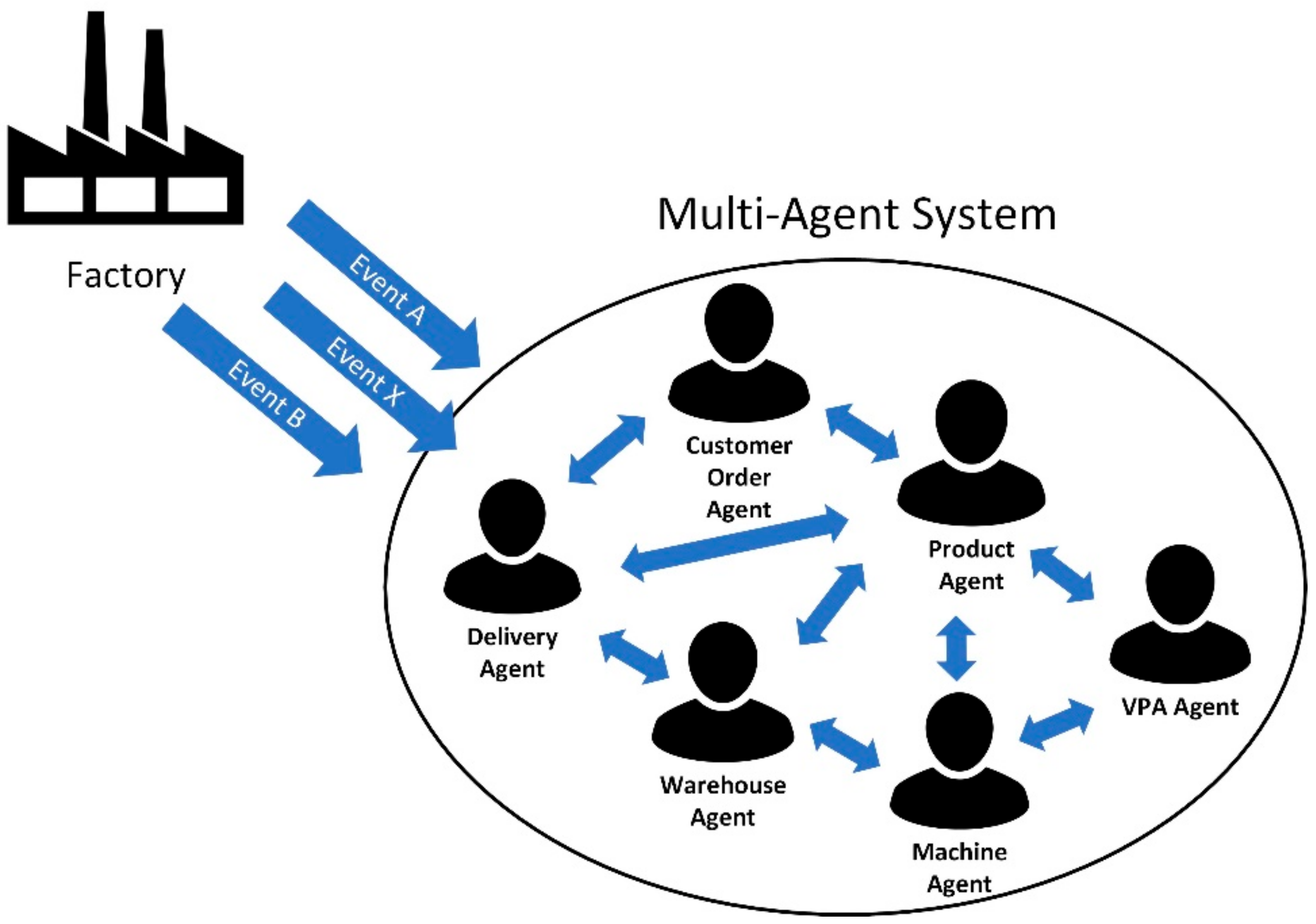
Within the adopted model, an agent receives both messages from other agents and external signals from the environment. The external signals are the operations of the production process (according to the synthetic description provided in
Section 2) that are turned into messages. The following main agents are involved in the MAS (see
Figure 2):
Product Agents are responsible for storing and handling all the information related to the products along the entire production chain, such as current process parameters and production steps.
Process/Machine Agents handle the production lines of the plant. They manage the information related to the machines’ settings, the number of the products to be processed, the scheduling of the products, etc. They can also suspend and reactivate the products whenever the production lines are full.
Warehouse Agents manage the warehouses of the plant by moving products from one place to another within the warehouses and towards the machines.
Virtual Product Allocator (VPA) Agent is a supervisor that acts like a broker agent but with an enhanced knowledge. The aim of the VPA is to manage the rerouting of the products if one of the production machines suffers a fault or is subject to maintenance operations. Another feature of the VPA is the reallocation of products that are no more compliant with a customer order, i.e., products that no longer satisfy all the requirements of the customer they were originally devoted to.
Delivery Agent handles the dispatching of the products. Its aim is to load products on trucks and to ship them to customers.
Customer Order Agents are responsible for the information about production orders. They interact with Product Agents whenever these latter need to check their quality target parameters.
3.1. Agents Communication
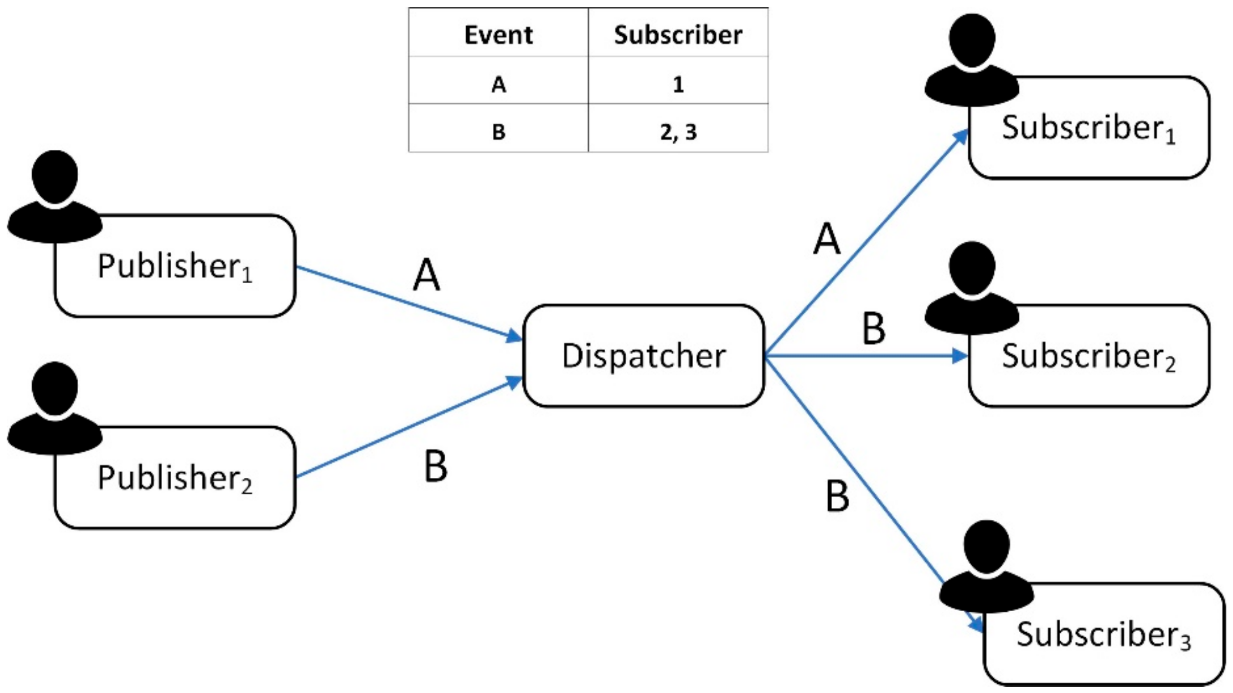
In order to deal with the event-driven system and the asynchronous messaging of the actor model, the communication mechanism adopted for the agents is based on the distributed event-based system, also called the Publish–Subscribe model [
20]. This is an indirect communication method among distributed entities that communicate through a Dispatcher or Broker without any direct connection between the sender and the receiver. The Publish–Subscribe system supports cooperative work where a number of participants need to be informed on shared interest events. Moreover, it is used in several applications such as financial systems, Feed RSS, network monitoring, etc., [
21,
22]. An example of a Publish–Subscribe communication scheme is reported in
Figure 3.
For instance, when a product X is ready to be loaded into the buffer of the machine Y (i.e., operation code 3), then Product Agent X, Machine Agent Y and Warehouse Agent Z are informed. In this specific case, the Machine Agent Y can check if is able to process the product X, Warehouse Agent Z can check where the product X is located and Product Agent X can control its own status. At the same time, other actions can be performed by the agents. Another example concerns the situation in which product X needs to know its own quality target parameters after being worked. The Product Agent X publishes a message requiring the necessary information so that the Customer Order Agent responsible for the product X is notified. The previous two examples are two situations depicting how the Publish–Subscribe mechanism is used to deal with both production operations events and message exchange among agents.
3.2. Agents Behavior
The agents’ high-level behavior as well as the decision rules that manage the operations and the interactions of the agents are described by using the Business Process Models and Notation (BPMN). Even though the behavior of agents in ABS models can be expressed in other modeling languages such as Petri Nets or through the Agent Unified Model Language (AUML), a requirement under the project for which the presented MAS was developed concerned the adoption of a user friendly representation for business users. BPMN represents a powerful tool in this context, as it is easy to understand and supports several diagrams, such as process and collaboration diagrams. The use of BPMN for modeling agents’ behavior was presented in different papers [
23,
24]. Considering the formalism proposed in reference [
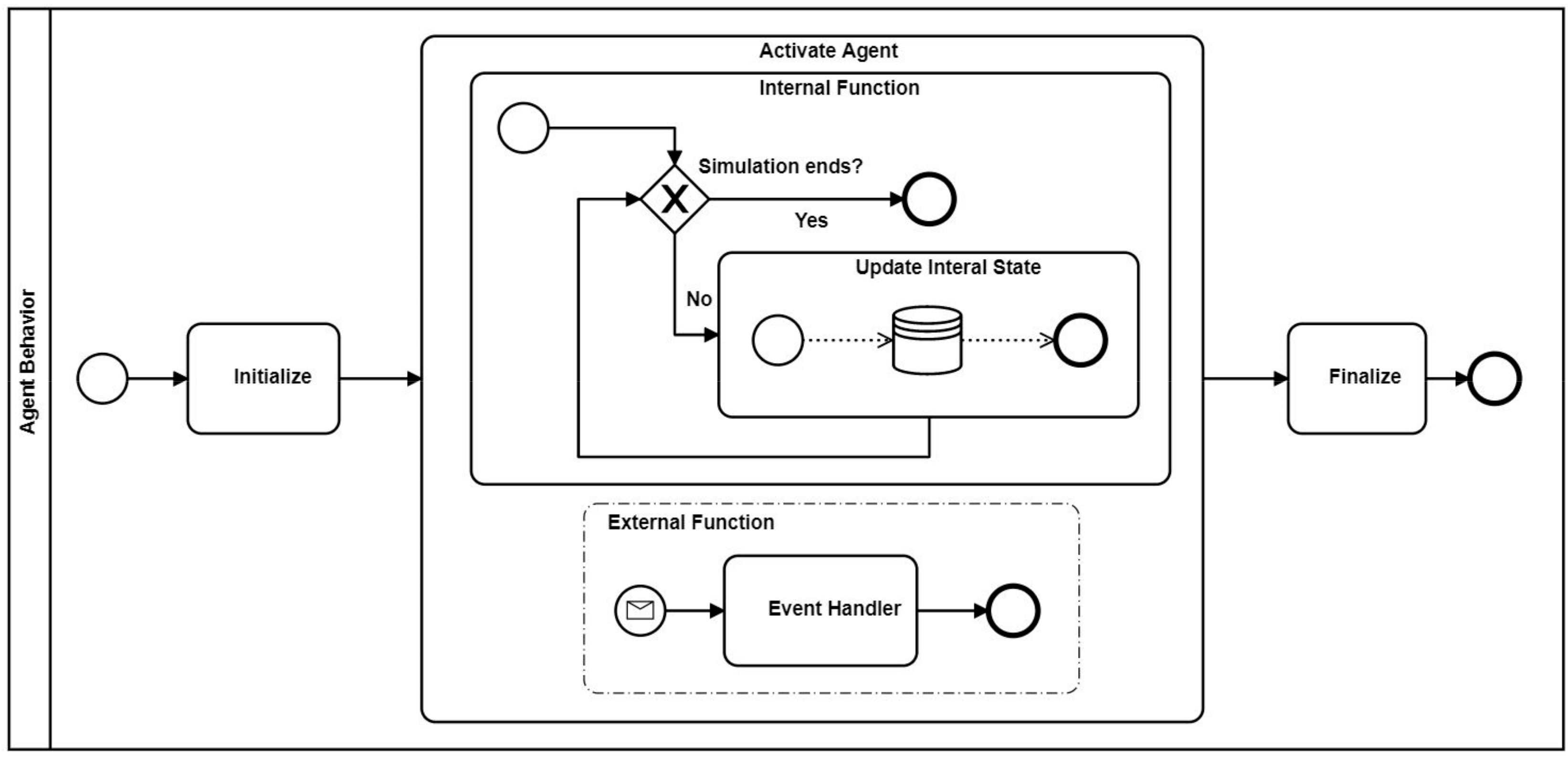
23], the general behavior of an agent can be represented as shown in
Figure 4. In particular, the “Activate Agent” sub-process encapsulates the main body of the agent. Once the agent is activated, it is ready to perform different actions. The “Internal Function” is used to maintain, up to date, the internal state of the agent until the simulation ends, whereas the “External Function” is used to handle external events such as the operations coming from the plant and the messages coming from the other agents. A description of the interaction among agents in case of unexpected events such as faults, products reallocation, and machine overload are reported in the next subsections.
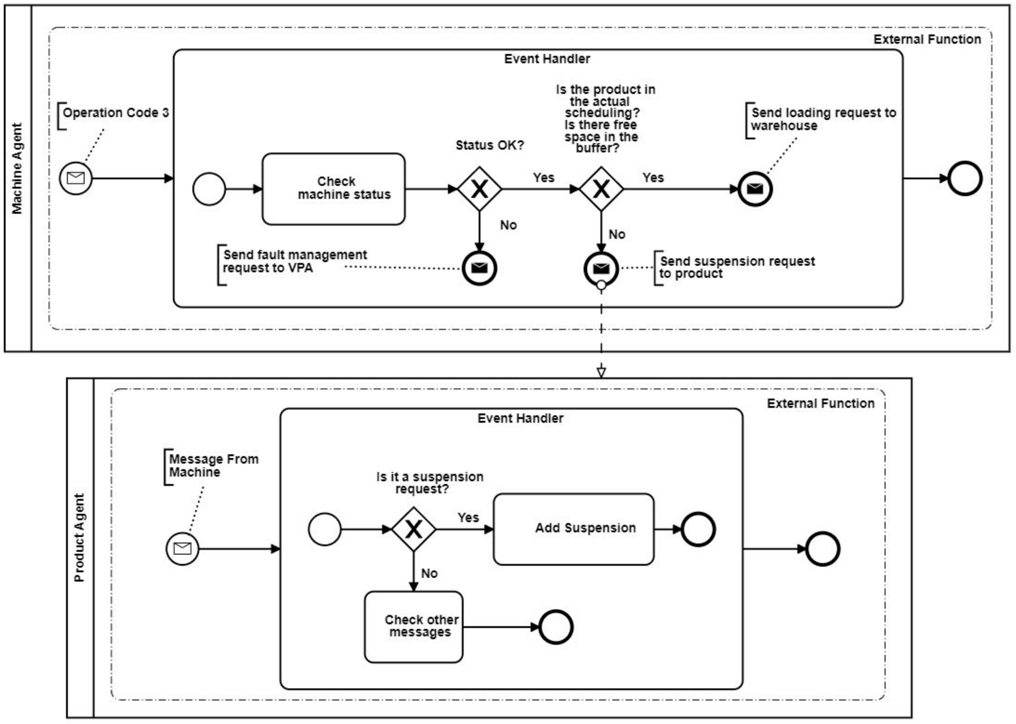
3.2.1. Product Suspension
The interaction between Machine Agent and Product Agent as well as their behavior when the loading event (i.e., operation code 3) occurs is depicted in
Figure 5.
The Machine Agent, before loading a new product in its entry buffer, checks if the status of the machine is good; otherwise, it sends a fault management request to the VPA Agent. If everything is satisfactory, then the machine controls whether the scheduling contains the coming product and if the entry buffer is free to allocate a new incoming product. If at least one of the previous controls is not satisfied, then the Machine Agent sends a suspension request to the Product Agent, which suspends the product waiting to be worked. The suspension state of the Product Agent is not always the same, but depends on the type of suspension request received, which includes a code that specifies the type of suspension. Therefore, a suspension for a full buffer is different from a suspension for incorrect scheduling.
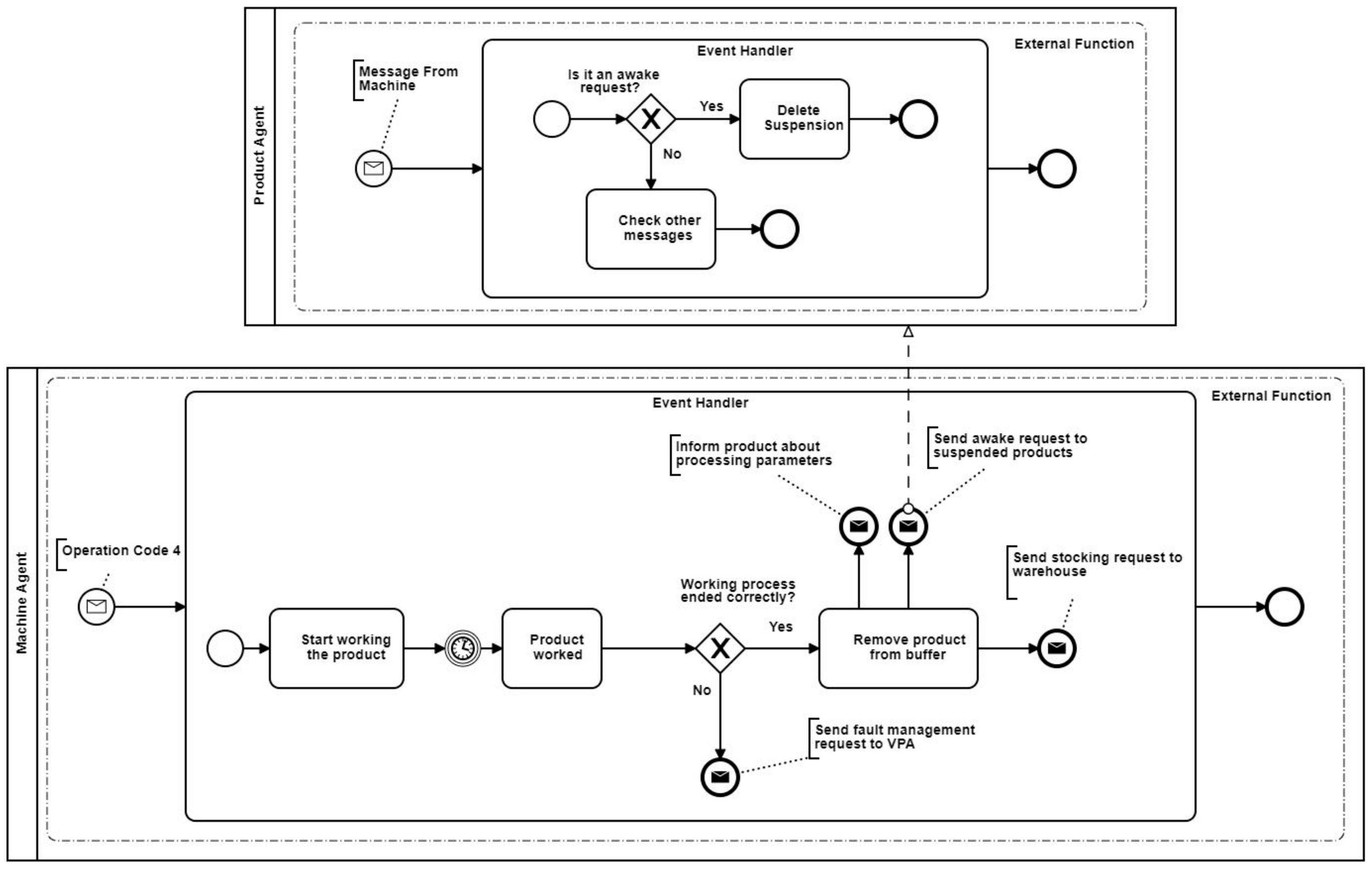
3.2.2. Product Reactivation
The interaction between Machine Agent and Product Agent as well as their behavior when the working event (i.e., operation code 4) occurs is depicted in
Figure 6. The Machine Agent, after working the product, checks if the process terminates correctly. If some problem occurred during the processing, it sends a fault request to the VPA Agent that will handle the event, otherwise the Machine Agent removes the product and will send three messages:
An update message to the Product Agent that handles the semi-finished product. The update message contains information about the processing parameters.
An awake request message to the Product Agents suspended.
A stocking request message to the Warehouse Agent that is in charge of finding a location for the semi-finished product and to stock it into the warehouse.
The Product Agent shown in
Figure 6 handles the reactivation of the product. When the Product Agent receives an awake request from the Agent Machine, it removes the suspension and makes the product ready to be loaded by the machine again.
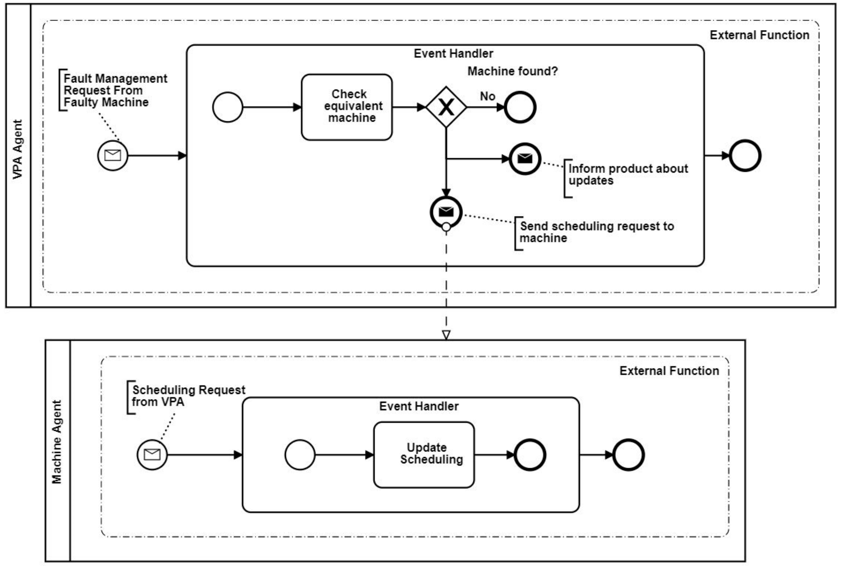
3.2.3. Fault Management
The interaction between Machine Agent and VPA Agent as well as their behavior when a fault occurs is depicted in
Figure 7.
As already mentioned, a machine might have one or more equivalent machines that perform exactly the same kind of operations with different or equal processing speed. In this way, it is possible to reallocate the products, which are already assigned to a machine, to its equivalent one, in case of faults. When the VPA Agent receives a fault management request by a faulty machine, it checks if there is another equivalent machine. If the VPA Agent finds an equivalent machine, it sends both a scheduling request to the Machine Agent and an update message to the Product Agents. The Machine Agent adds the new products to be processed to its current scheduling and the Product Agents are notified with the new scheduling of the products. On the other hand, if the equivalent machine is not found, the VPA Agent does not perform any operation, leaving the schedule for the faulty machine unaltered.
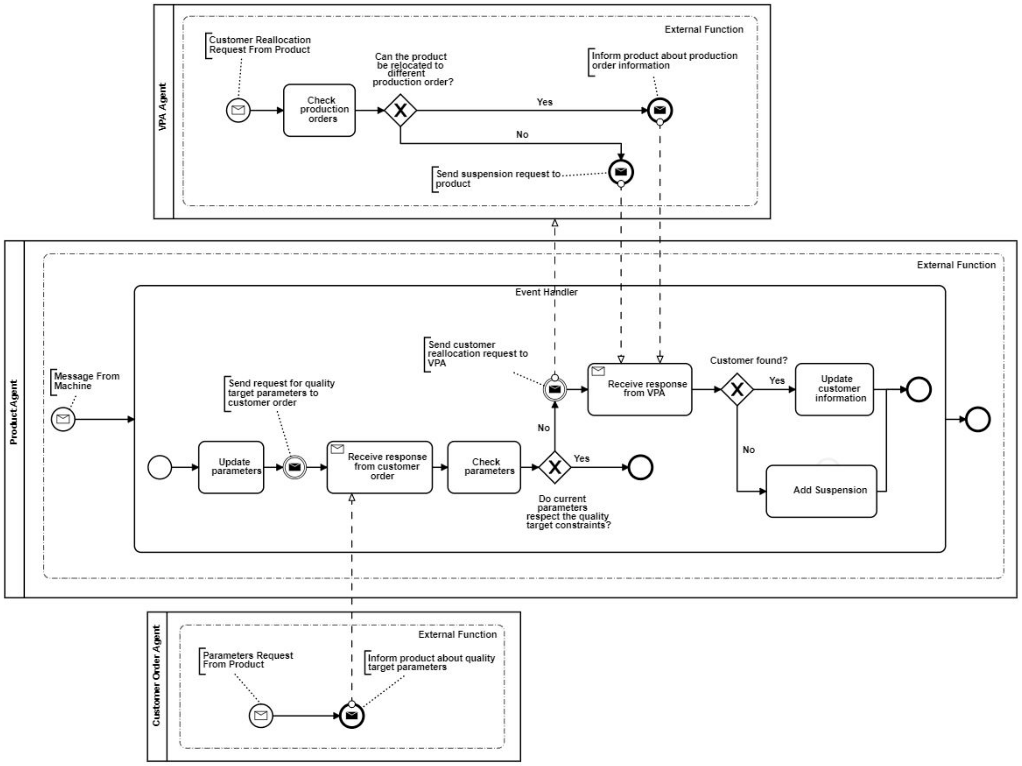
3.2.4. Product Reallocation
The interaction between Product Agent, Customer Order Agent and VPA Agent as well as their behavior when a reallocation occurs is depicted in
Figure 8.
After being processed by a machine, a Product Agent receives the updated processing parameters by the Machine Agent, as shown in
Figure 6. The Product Agent is able to compare the new parameters with those ones required by the customer. Therefore, the Product Agent sends a request to the Customer Order Agent in order to know the quality target parameters. After receiving the response from the Customer Order Agent, the Product Agent checks if the new processing parameters respect all the quality target constraints. If the constraints are not satisfied, then the Product Agent sends a customer reallocation request to the VPA Agents. The VPA Agent will try to find a new customer order for the product and if a new one is found, the VPA Agent will inform the Product Agent. In this way, the product is reallocated to a new customer and the Product Agent can update its customer information, whereas if a new customer is not found, the VPA Agent sends a suspension request to the Product Agent and it becomes available for a new reallocation in the future.
4. Software Architecture
A MAS may be implemented by using any kind of programming language. In particular, object-oriented programming (OOP) languages represent a good solution, as they share some properties with the agents’ concepts, but they are also used for implementing agent frameworks and development toolkits. C# (C-Sharp) was selected among the different OOP languages in combination with Microsoft Visual Studio environment and NET Framework platform, whose components represent a standard [
25]. Basically, C# offers several advantages compared to other languages, as it integrates a “garbage collection” system, it is supported by several standard libraries and frameworks, it has a simple implementation of properties and events, it is an elegant option for “embedded systems” for the integration in industrial plants and it is also a multiplatform language.
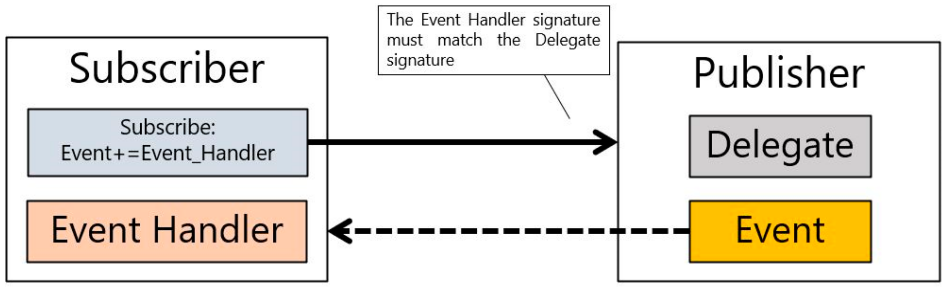
The Publish–Subscribe mechanism is implemented through the Event and Delegate pattern of C#. A delegate is like a pointer to a function, while an event is nothing but an encapsulated delegate. An example of the Publish–Subscribe pattern in C# is shown in
Figure 9.
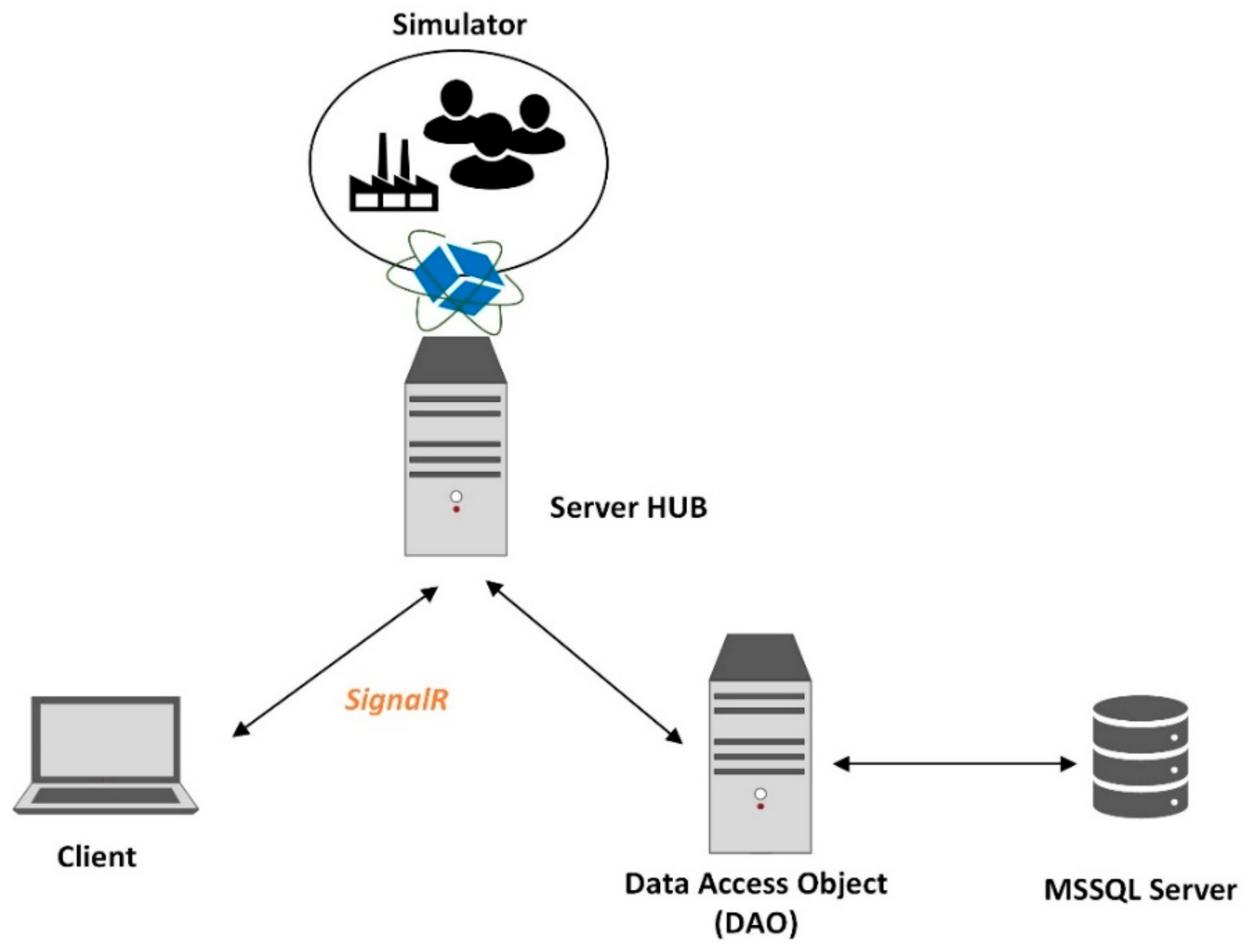
In order to simulate the agent-based model, a web-based application was implemented through ASP.NET toolkit of .NET Frameworks 4.0 that allows the creating of classical web-apps, REST API, real-time web-apps and micro-services. The SignalR library included in the ASP.NET allows for the realizing of web applications with real-time bidirectional communication between client and server, suitable for monitoring applications that require continuous and constant updates at high frequency from the server. SignalR supports techniques for managing real-time communication (e.g., WebSocket objects, events sent by the servers and long polling) and automatically selects the best transport method within both server and client functionality. SignalR uses Hubs for the communication between clients and server. A Hub allows performing of a Remote Procedure Call (RPC) from a server to connected clients and vice versa.
Concerning data access, a relational Data Base (DB) with Microsoft SQL Server and two patterns of access to data DAO (Data Access Object) and DTO (Data Transfer Object) have been created. The first one encapsulates the logic for accessing, recovering and saving data on the database. The second one, instead, is mainly used to transfer data between the different objects within the application. A schematic representation of the software architecture is provided in
Figure 10. The designed software architecture is modular and flexible and can be deployed to the existing IT systems in the company. A possible solution in order to integrate the proposed software into the IT system of a company consists of exploiting a technical integration strategy, such as reported in reference [
26]. For instance, a data integration approach can be implemented, which integrates the Enterprise Resource Planning (ERP) data with the agent-based system, since the ERP systems can be considered technologically and operationally ready for the factory of the future [
27]. Another approach that can be used is presented in reference [
28], where a technical integration strategy for the deployment of a CPPS platform according to the ISA 95 automation standard is described.
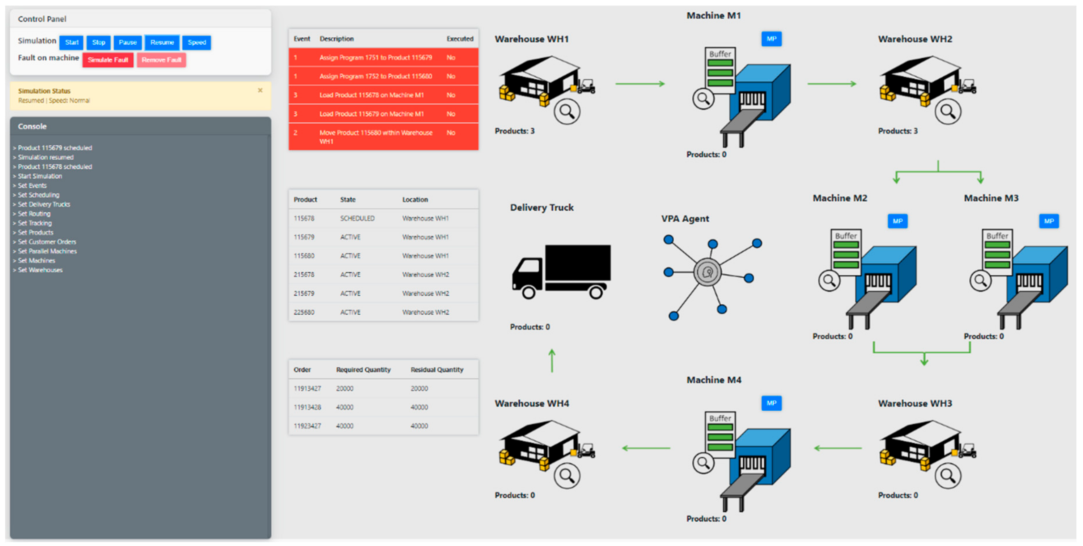
The simulator graphical user interface (GUI) is shown in
Figure 11. On the right side, a schematic view of the production process described in
Section 2 is proposed. It is possible to interact with the graphical objects such as warehouses and machines and check the list of products inside them.
There are also three tables: the table at the top shows the events occurring during the simulation, the table in the center summarizes products information such as their status, their identification number and their location and, finally, the table at the bottom shows the status of the production orders with the production demand and the products already delivered. On the left side, there is the control panel by which the user can manage the simulation, a status bar and a console where detailed information about the simulation are printed.
The simulation can be easily followed by the end-user, using the graphical representation and it can be also possible to stop, resume and halt the simulation through the control panel. Moreover, the simulation speed can be altered, so that every operation can be analyzed and checked in an easy way. Furthermore, it is possible to simulate faults and maintenance operations in machines as well as restore their normal conditions.
The simulator can be used in two different modes and each of them is related to a different type of simulation:
An event models a change in the system and can be a scheduled operation already described in
Table 1, a fault or a message received by an agent. Each event is associated to a start time and the duration of an event depends on the processes occurring in the system. Every time a new event is published, the agents react by accomplishing one or more actions according to their behavior.
5. Simulation Experiments and Results
In this section, a description of the scenarios used to test the developed agent-based simulation model is provided. One undisturbed scenario and three dynamic scenarios were simulated to show how the agent-based system can adapt its behavior within different situations. During the dynamic scenarios, the system must react to unforeseen events such as faults, off-spec productions and overloading of the machines.
5.1. Undisturbed Scenario
In the undisturbed scenario, the system must process six products with different characteristics. The products are characterized by physical and quality parameters like weight, thickness, width, length, and quality type, and they were ordered by some customers with specific requirements. A detail of the products information is reported in
Table 2. The information about the production orders are summarized in
Table 3, where the quality target parameters with their tolerances are reported. Initially, the first three products in
Table 2 are located in Warehouse WH1, whereas the last three products are located in Warehouse WH2. The expected scheduling of the machines was set as reported in
Table 4, whereas the events generated sequentially by the simulator are summarized in
Table 5.
The operations in
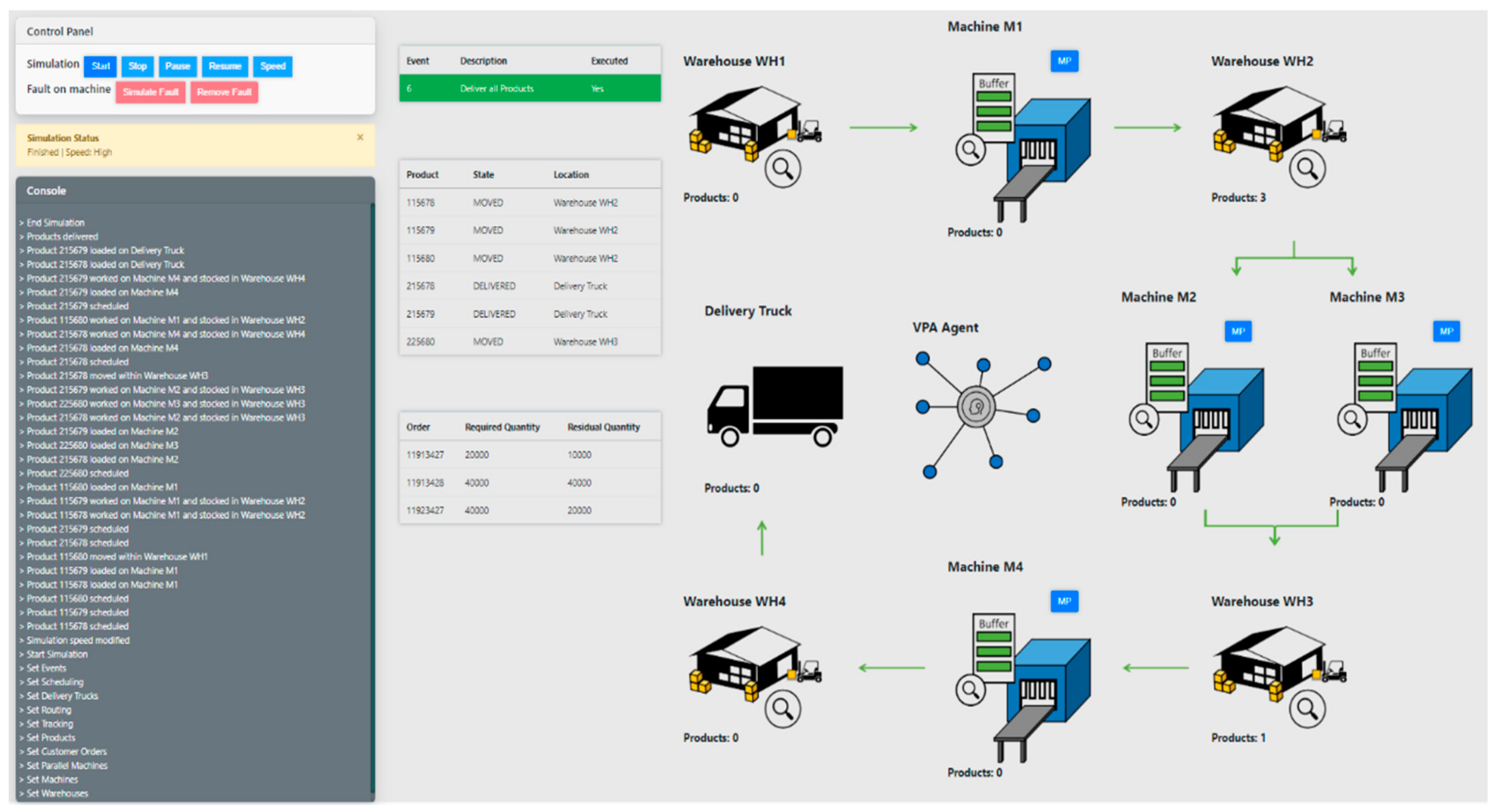
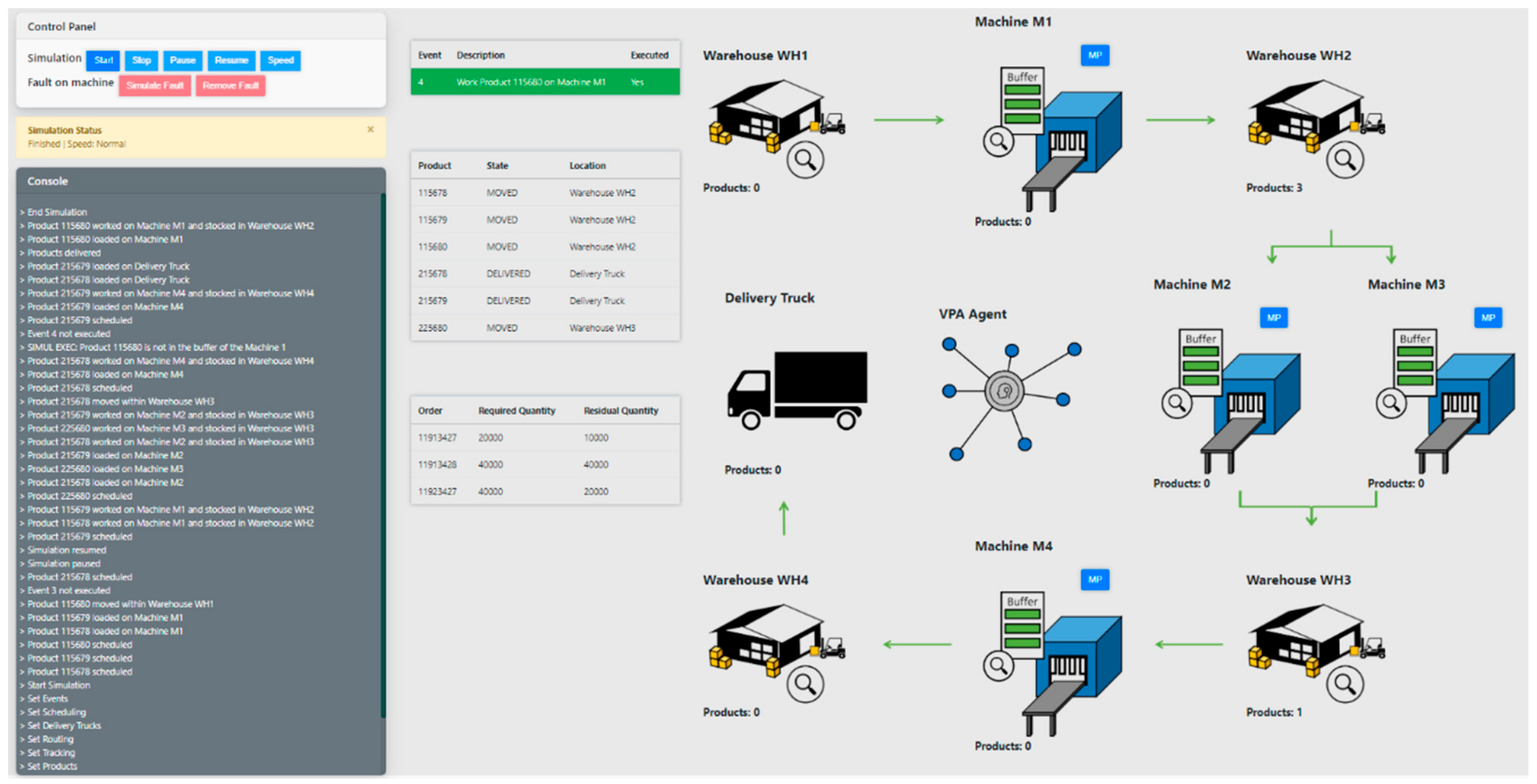
Table 4 are arranged to process and deliver products 215678 and 215679, while the processing of the other products remains uncompleted. A representation of the plant at the end of the simulation is shown in
Figure 12. The simulation ends as expected without unforeseen events and the MAS orchestrates the system, accomplishing all the designed operations. During the simulation, the machine scheduling is fixed, but the Machine Agents might be rescheduling the products in a different manner, e.g., by minimizing product tardiness.
5.2. Machine Overloading Scenario
In this scenario, a product was deliberately loaded on the Machine M1, even if the buffer capacity of the machine does not support three products at a time but only two. The modified events are reported in
Table 6, where the unexpected operation is highlighted in bold and framed. In this case, when the unexpected event is executed, Machine Agent M1 sends a suspension request to the Product Agent 115680 that suspends the product, such as described in
Section 3.
An extraction of the simulation log is reported in
Table 7, where it is possible to see the messages exchanged between the Machine Agent and the Product Agent. Despite the suspension, product 115680 is reactivated as soon as the buffer of machine M1 is free. A representation of the plant at the end of the simulation is shown in
Figure 13, where the simulation correctly terminates with the processing of product 115680. Even in this case, the MAS orchestrates the system and is able to handle the unforeseen event. Even if the scenario described here rarely happens in a system that is manually managed, it can occur in an automated system. Therefore, a good management of product loading is necessary. The reactivation of the products could be managed directly by the Product Agents, by asking to be reprocessed after a while, but this is not efficient as the products do not know exactly when a machine is ready, thus, the reactivation is handled by the Machine Agents.
5.3. Machine Fault Scenario
In this scenario, a fault is generated on machine M2 during the simulation, and therefore, the products scheduled on M2 are rescheduled to machine M3. The events generated sequentially by the simulator are those of the undisturbed scenario, but after three operations, a fault was generated by clicking on the “Simulate Fault” button over the control panel. In this case, when the loading event (i.e., operation code 3) is published by the simulator, then Machine Agent M2 checks its status and sends a fault management request to the VPA Agent that will handle the request by sending, in turn, a scheduling request to Machine Agent M3.
An extraction of the simulation log is reported in
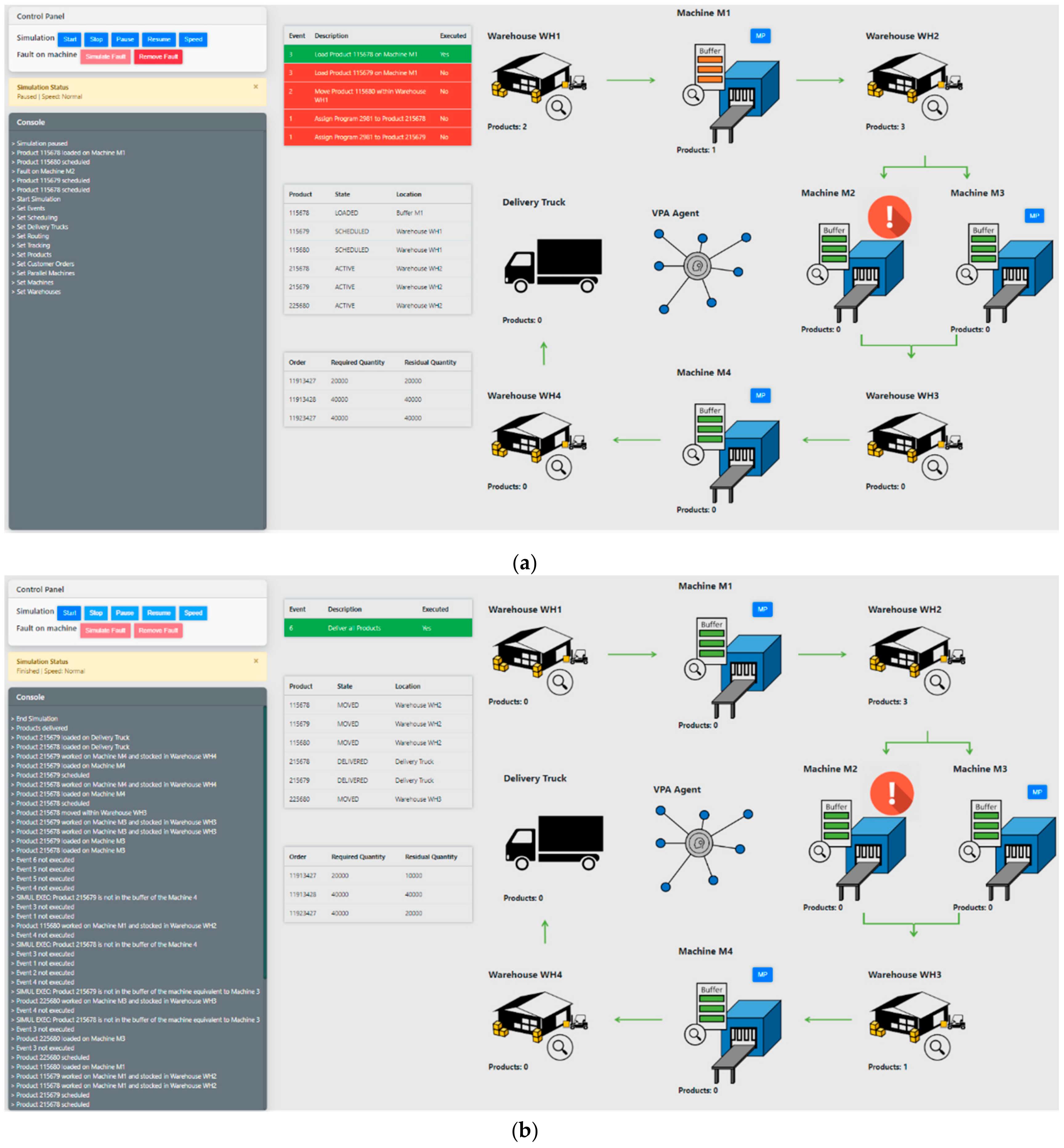
Table 8, where it is possible to see the messages exchanged between the Machine Agents and the VPA Agent. Despite the fault, the products 215678 and 215679 are successfully processed and delivered. A photograph of the plant at the beginning of the simulation is shown in
Figure 14a, while
Figure 14b reports a snapshot of the end of the simulation, where the correct completion of the simulation is shown. Even in this case, the MAS orchestrates the system and is able to handle the unforeseen event. Regarding Machine Agent M2’s behavior in case of faults, it could send a fault request directly to Machine Agent M3 without the intercession of the VPA Agent. In this case, the number of exchanged messages can be reduced, but Machine Agent M3 should subscribe to fault management requests coming from Machine Agent M2 by augmenting its knowledge of the system.
5.4. Customer Reallocation Scenario
In this scenario, a customer reallocation is simulated by altering the quality requirements of a customer order. The order 11913428 is modified, as highlighted in bold in
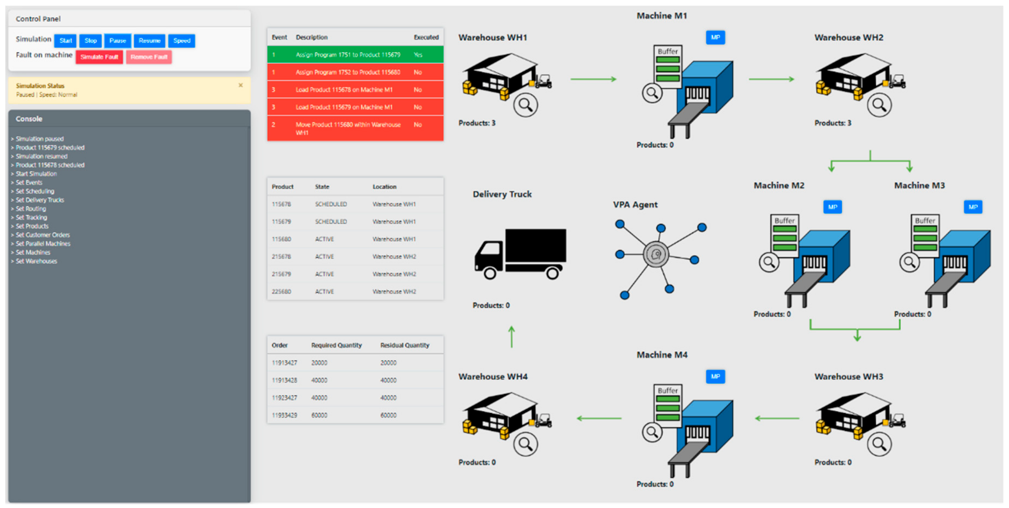
Table 9, and also a new customer order, i.e., 11933429, is added at the end of the table. A photograph of the plant at the beginning of the simulation is shown in
Figure 15, where the table on the bottom contains the new production orders information. As already explained in
Section 3, Product Agents 115679 and 225680 check their parameters after being worked and if the parameters violate some of the quality target constraints, they send a customer reallocation request to the VPA Agent. In this case, the VPA Agent is able to reallocate both products to customer order 11933429 because the new parameters of the products are compliant with those of the customer order.
An extraction of the simulation log is reported in
Table 10, where it is possible to see the messages exchanged between the Product Agents and the VPA Agent. Even in this case, the MAS orchestrates the system and is able to handle the unforeseen events. Regarding the reallocation process performed by VPA, some improvement can be considered by looking at some performance parameters to optimize. For instance, the allocation process can be performed by minimizing the customer quality requirements’ deviation. The Product Agents could also start the Contract Net Protocol (CNP) with the Customer Orders Agents by solving the customer reallocation task without the intercession of the VPA Agent. As a result, the MAS structure is more decentralized, but the number of exchanged messages is increased.
6. Conclusions
Process manufacturing industries are complex and dynamic systems composed of several processes and subject to many operations. Industry 4.0 makes use of technologies that pave the way for the transformation of a traditional process industry into a smart factory, a paradigm that affects not only the technologies used to be more productive, but it means a system that will be fully connected, flexible and intelligent and will be capable of generating new business models. In this scenario, the innovation process beyond the smart factory affects also the traditional managerial chain, where the speed into the decision-making process is a valuable skill. In this context, the ability of coping with an unforeseen event is of utmost importance and a multi-agent system is certainly the most suitable candidate for the design of distributed and intelligent applications in a complex and dynamic environment.
This paper presents an event-driven agent-based simulation model for simulating and controlling the operations of a general industrial process. The developed MAS is composed of eight reactive agents modeled by means of the actor approach and using the publish–subscribe paradigm in order to allow the agents to communicate with each other. The agents’ high-level behavior of the proposed MAS was described by using the BPMN formalism and the interaction among the agents in different situations such as fault management, products reallocation and suspension was reported in detail. A web-based application was implemented through the ASP.NET toolkit of .NET Frameworks 4.0 to simulate the agent-based model. The GUI of the application allows the user to control the simulation and interact with it, showing also how the system process evolves over time.
Different scenarios were simulated to show how the agent-based model can handle unexpected dynamic events such as off-spec products, machine faults or overloading on a single machine. Even if the considered scenarios represent a simplified version of real plant situations and the performance of the production process is far from optimal, the simulations show the potential and the advantages of the designed MAS approach and highlight that this paradigm can be transferred within an industrial environment in order to promptly react to different dynamic scenarios and to handle different unforeseen situations. The proposed agent-based model architecture is a hybrid due to the presence of VPA Agent, which inhibits the complete decentralization of the MAS structure but provides a high-level view of the plant and reduces the number of exchanged messages. The adopted communication model is fast and efficient and can be a suitable point of strength to considerably reduce the delay related to the information transfer among the involved actors by increasing the availability of useful information to feed the decision-making process. Furthermore, the developed modular system architecture is flexible and integrable with the existing IT systems of a company.
Future work will deal with the improvement of the agent-based system by exploiting optimization algorithms to predict faults, optimize the machine scheduling and the allocation of the production orders in order to improve the overall performance of the production system. Furthermore, more complex scenarios will be considered, tests on real data will be performed to assess the goodness of the agent-based simulation model, and the final deployment of the solution on a real industrial plant will be carried out.

 ,
, 


