Surface Optimization of Micro-Integrated Reflective Optical Elements by Thermoset Injection Molding

 and
and 
Abstract
1. Introduction
2. Materials and Methods
2.1. Materials
2.2. Mold Design
2.3. Injection Molding
3. Results
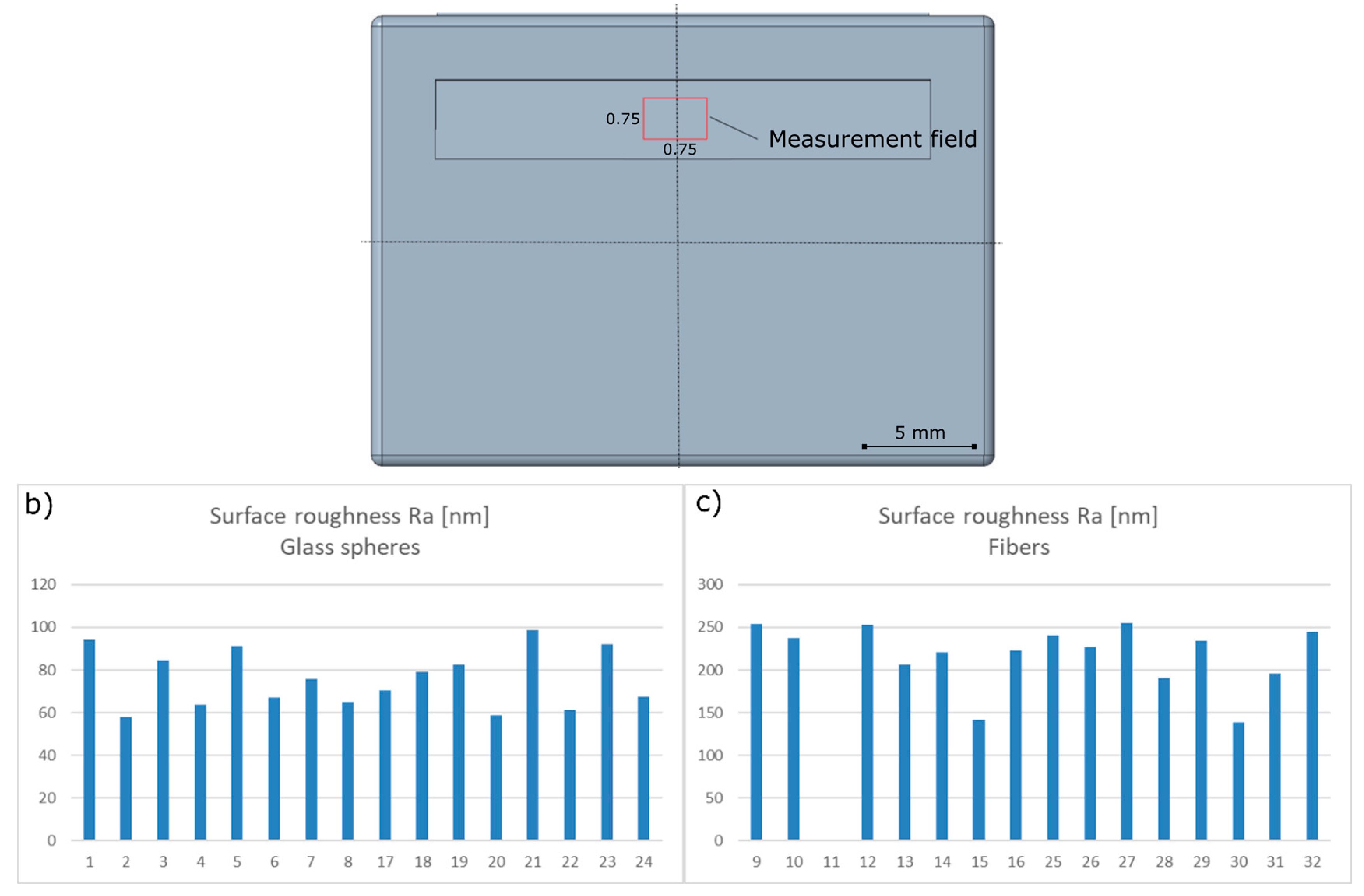
3.1. Measurements
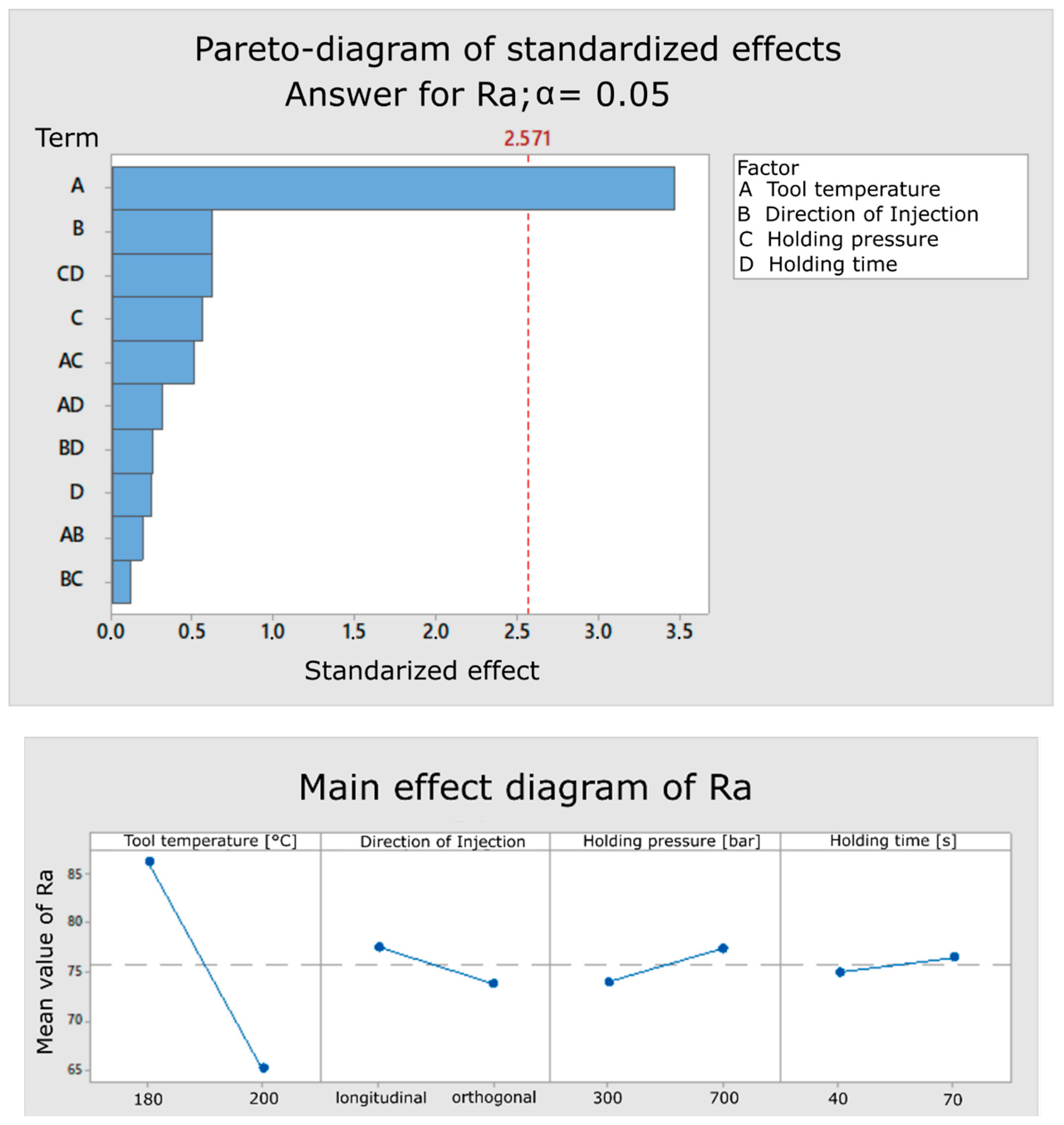
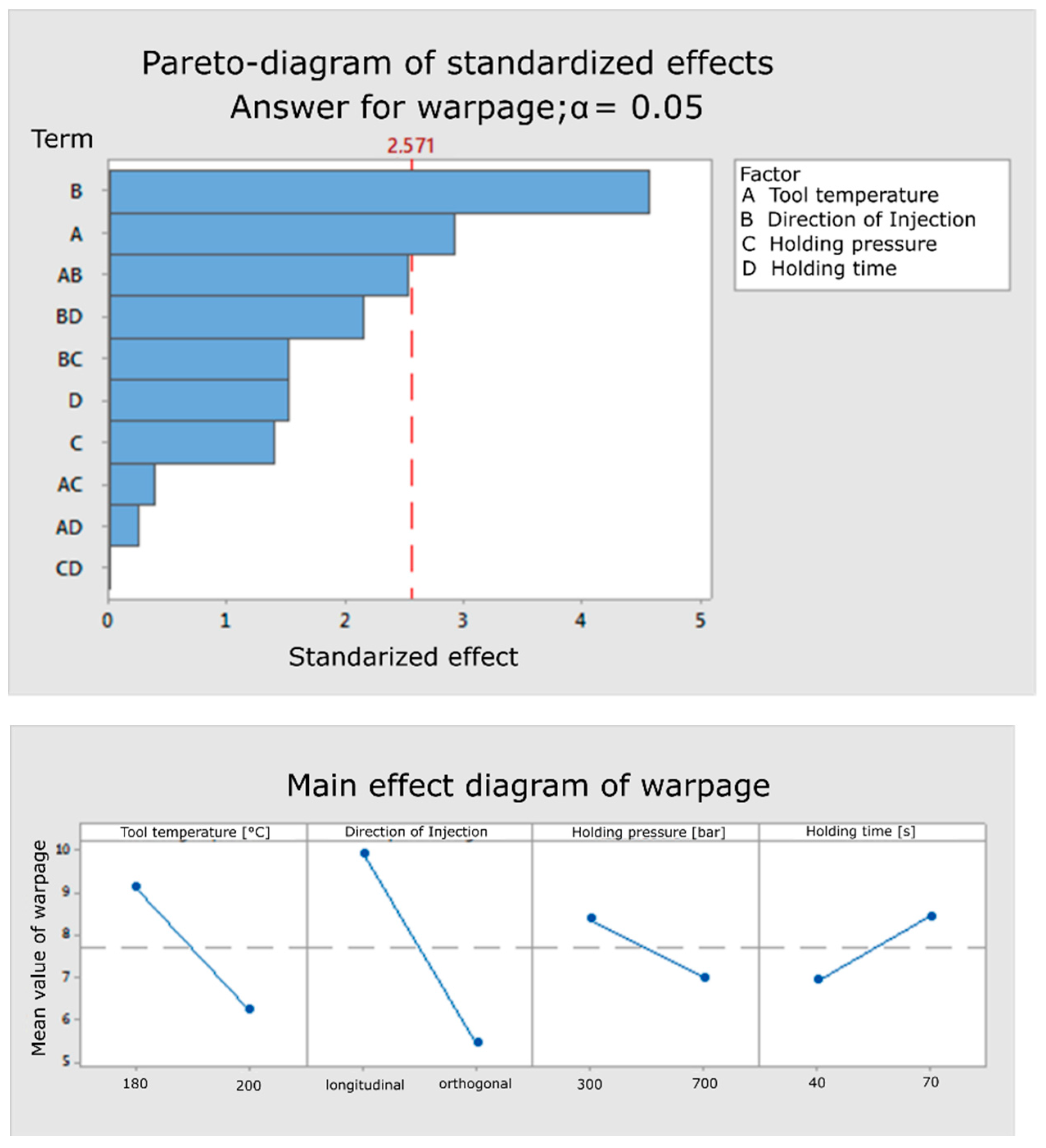
3.2. Evaluation
4. Discussion
5. Conclusions
Author Contributions
Funding
Acknowledgments
Conflicts of Interest
Appendix A

| Standard Order | Processing Order | Tool Temp-Erature [°C] | Direction of Injection | Holding Pressure [°C] | Filler Geometry | Holding Time [s] | Roughness Ra [nm] | Shrinkage [%] | Warpage [µm] |
|---|---|---|---|---|---|---|---|---|---|
| 1 | 1 | 180 | longitudinal | 300 | Spheres | 40 | 94.306 | 0.41 | 14.5 |
| 2 | 15 | 200 | longitudinal | 300 | Spheres | 40 | 57.77 | 0.51 | 5 |
| 3 | 7 | 180 | orthogonal | 300 | Spheres | 40 | 84.49 | 0.49 | 6 |
| 4 | 12 | 200 | orthogonal | 300 | Spheres | 40 | 63.64 | 0.53 | 5 |
| 5 | 4 | 180 | longitudinal | 300 | Spheres | 40 | 91.055 | 0.51 | 8 |
| 6 | 14 | 200 | longitudinal | 700 | Spheres | 40 | 67.03 | 0.48 | 5 |
| 7 | 8 | 180 | orthogonal | 700 | Spheres | 40 | 75.66 | 0.55 | 5.5 |
| 8 | 9 | 200 | orthogonal | 700 | Spheres | 40 | 65.045 | 0.56 | 6.5 |
| 9 | 32 | 150 | longitudinal | 300 | Fibers | 5 | 254 | 0.52 | 8 |
| 10 | 19 | 190 | longitudinal | 300 | Fibers | 5 | 237.15 | 0.49 | 6 |
| 11 | 28 | 150 | orthogonal | 300 | Fibers | 5 | not | processable | |
| 12 | 21 | 190 | orthogonal | 300 | Fibers | 5 | 253.06 | 0.51 | 6 |
| 13 | 30 | 150 | longitudinal | 700 | Fibers | 5 | 206.415 | 0.47 | 7.5 |
| 14 | 17 | 190 | longitudinal | 700 | Fibers | 5 | 220.695 | 0.63 | 8.5 |
| 15 | 27 | 150 | orthogonal | 700 | Fibers | 5 | 141.27 | 0.54 | 13 |
| 16 | 22 | 190 | orthogonal | 700 | Fibers | 5 | 222.405 | 0.54 | 5.5 |
| 17 | 3 | 180 | longitudinal | 300 | Spheres | 70 | 70.385 | 0.5 | 14 |
| 18 | 16 | 200 | longitudinal | 300 | Spheres | 70 | 79.27 | 0.48 | 12 |
| 19 | 5 | 180 | orthogonal | 300 | Spheres | 70 | 82.625 | 0.56 | 5.5 |
| 20 | 10 | 200 | orthogonal | 300 | Spheres | 70 | 58.935 | 0.49 | 5 |
| 21 | 2 | 180 | longitudinal | 700 | Spheres | 70 | 98.92 | 0.49 | 14 |
| 22 | 13 | 200 | longitudinal | 700 | Spheres | 70 | 61.41 | 0.49 | 7 |
| 23 | 6 | 180 | orthogonal | 700 | Spheres | 70 | 92.035 | 0.5 | 5.5 |
| 24 | 11 | 200 | orthogonal | 700 | Spheres | 70 | 67.565 | 0.53 | 4.5 |
| 25 | 31 | 150 | longitudinal | 300 | Fibers | 20 | 241.035 | 0.59 | 8 |
| 26 | 18 | 190 | longitudinal | 300 | Fibers | 20 | 226.9 | 0.45 | 6.5 |
| 27 | 25 | 150 | orthogonal | 300 | Fibers | 20 | 254.78 | 0.6 | 6 |
| 28 | 24 | 190 | orthogonal | 300 | Fibers | 20 | 190.54 | 0.61 | 7 |
| 29 | 29 | 150 | longitudinal | 700 | Fibers | 20 | 233.94 | 0.56 | 7 |
| 30 | 20 | 190 | longitudinal | 700 | Fibers | 20 | 138.775 | 0.52 | 6.5 |
| 31 | 26 | 150 | orthogonal | 700 | Fibers | 20 | 195.505 | 0.52 | 5.5 |
| 32 | 23 | 190 | orthogonal | 700 | Fibers | 20 | 245.025 | 0.51 | 12.5 |
References
- Photonics 21. Photonics—A critical Key Eneabling Technology for Europe: Role and Impact of Photonics in H2020; VDI Technologiezentrum GmbH: Dusseldorf, Germany, 2018. [Google Scholar]
- Yun, Z.; Lam, Y.L.; Zhou, Y.; Yuan, X.; Zhao, L.; Liu, J. Eyepiece design with refractive-diffractive hybrid elements. In Current Developments in Lens Design and Optical Systems Engineering, the Proceedings of the International Society for Optics and Photonics, International Symposium on Optical Science and Technology, San Diego, CA, United States, 24 October 2000; Society of Photo Optical: Bellingham, WA, USA, 2000; Volume 4093, pp. 474–481. [Google Scholar]
- Cox, J.A.; Fritz, T.A.; Werner, T.R. Application and demonstration of diffractive optics for head-mounted displays. In Helmet- and Head-Mounted Displays and Symbology Design Requirements, the Proceedings of the International Society for Optics and Photonics, SPIE’s International Symposium on Optical Engineering and Photonics in Aerospace Sensing, Orlando, FL, USA, 10 June 1994; Society of Photo Optical: Bellingham, WA, USA, 1994; Volume 2218, pp. 32–41. [Google Scholar]
- Kress, B.; Starner, T. A review of head-mounted displays (HMD) technologies and applications for consumer electronics. In Photonic Applications for Aerospace, Commercial, and Harsh Environments IV, the Proceedings of the International Society for Optics and Photonics, SPIE Defense, Security, and Sensing, Baltimore, MD, USA, 29 April–1 May 2013, Society of Photo Optical: Bellingham, WA, USA, 2013; Volume 8720, p. 87200A.
- Nakai, T.; Ogawa, H. Research on multi-layer diffractive optical elements and their application to camera lenses. In Diffractive Optics and Micro-Optics; OSA Trends in Optics and Photonics Series; paper DMA2; Magnusson, R., Ed.; Optical Society of America: Washington, DC, USA, 2002; Volume 75. [Google Scholar]
- Early, J.T.; Hyde, R.; Baron, R.L. Twenty-meter space telescope based on diffractive Fresnel lens. In UV/Optical/IR Space Telescopes: Innovative Technologies and Concepts, the Proceedings of the International Society for Optics and Photonics, Optical Science and technology, SPIE’s 48th Annual Meeting 30 January 2003, San Diego, CA, USA; Society of Photo Optical: Bellingham, WA, USA, 2004; Volume 5166, pp. 148–157. [Google Scholar]
- Spectaris—German Industry Association for Optics, Photonics, Analytical and Medical Technology. Spectaris, Trend Report Photonik 2019/2020—Markets, Developments, Potentials; Federal Ministry for Education and Research Germany: Berlin, Germany, 2019. [Google Scholar]
- Committee Optical Technologies. Agenda Photonik 2020; Federal Ministry for Education and Research Germany: Berlin, Germany, 2016. [Google Scholar]
- Brinksmeier, E.; Riemer, O.; Gläbe, R. Fabrication of Complex Optical Components; Springer-Verlag: Berlin/Heidelberg, Germany, 2013. [Google Scholar]
- Lin, C.-M.; Hsieh, H.-K. Processing optimization of fresnel lenses manufacturing in the injection molding considering birefringence effect. Microsyst. Technol. 2017, 23, 5689–5695. [Google Scholar] [CrossRef]
- Brinksmeier, E.; Gläbe, R.; Schönemann, L. Review on diamond-machining processes for the generation of functional surface structures. CIRP J. Manuf. Sci. Technol. 2012, 5, 1–7. [Google Scholar] [CrossRef]
- Roeder, M.; Schilling, P.; Hera, D.; Guenther, T.; Zimmermann, A. Influences on the fabrication of diffractive optical elements by injection compression molding. J. Manuf. Mater. Process. 2018, 2, 5. [Google Scholar] [CrossRef]
- Lee, B.-K.; Kim, D.S.; Kwon, T.H. Replication of microlens arrays by injection molding. Microsyst. Technol. 2004, 10, 531–535. [Google Scholar] [CrossRef]
- Beich, W.S. Injection molded polymer optics in the 21st-Centtury. In Proceedings of the SPIE Conference on Optics and Photonics 5865J, San Diego, CA, USA, 22 August 2005. [Google Scholar]
- Kim, D.S.; Lee, H.S.; Lee, B.-K.; Yang, S.S.; Kwon, T.H.; Lee, S.S. Replications and analysis of microlens array fabricated by a modified LIGA process. Polym. Eng. Sci. 2006, 46, 416–425. [Google Scholar] [CrossRef]
- Levoy, M.; Hanrahan, P. Light field rendering. In Proceedings of the 23rd Annual Conference on Computer Graphics and Interactive Techniques—SIGGRAPH ’96, New Orleans, LA, USA, 4–9 August 1996; ACM Press: New York, NY, USA, 1996; pp. 31–42. [Google Scholar]
- Levoy, M.; Zhang, Z.; Mcdowall, I. Recording and controlling the 4D light field in a microscope using microlens arrays. J. Microsc. 2009, 235, 144–162. [Google Scholar] [CrossRef] [PubMed]
- Shogenji, R.; Kitamura, Y.; Yamada, K.; Miyatake, S.; Tanida, J. Bimodal fingerprint capturing system based on compound-eye imaging module. Appl. Opt. 2004, 43, 1355–1359. [Google Scholar] [CrossRef] [PubMed]
- Dombrowski, M.; Catanzaro, B. Spatially Corrected Full-Cubed Hyperspectral Imager. U.S. Patent US7242478B1, 7 July 2007. [Google Scholar]
- Shogenji, R.; Kitamura, Y.; Yamada, K.; Miyatake, S.; Tanida, J. Multispectral imaging using compact compound optics. Opt. Express 2004, 12, 1643. [Google Scholar] [CrossRef] [PubMed]
- Hsieh, T.-C. MOS or CMOS Sensor with Micro-Lens Array. U.S. Patent US20060249765A1, 9 November 2006. [Google Scholar]
- Moore, S. LSR claims advantages over clear thermoplastics in lighting applications. Materials | Plastics Today. Available online: https://www.plasticstoday.com/injection-molding/lsr-claims-advantages-over-clear-thermoplastics-lighting-applications/16893490760703 (accessed on 24 April 2020).
- Sigloch, H. Technische Fluidmechanik, 6th ed.; Springer-Verlag: Berlin/Heidelberg, Germany, 2008. [Google Scholar]
- Lu, D.; Wong, C.P. (Eds.) Materials for Advanced Packaging; Springer: New York, NY, USA, 2009. [Google Scholar]
- Pecht, M.; Nguyen, L.T.; Hakim, E.B. (Eds.) Plastic-Encapsulated Microelectronics: Materials, Processes, Quality, Reliability, and Applications; Wiley: New York, NY, USA, 1995. [Google Scholar]
- Hoster, B. Hochwertige Oberflächen für Duroplastische Formteile. In Proceedings of the 7th Internationale Duroplasttagung, Iserlohn, Germany, 17–18 April 2013. [Google Scholar]
- Gardziella, A. Duroplastische Harze, Formmassen und Werkstoffe: Chemie, Eigenschaften, Wirtschaftliche Bedeutung, Aktuelle Anwendungen und Technologien; Expert Verlag: Renningen, Germany, 2000. [Google Scholar]
- Schwarz, O. Kunststoffkunde—Aufbau, Eigenschaften, Verarbeitung, Anwendungen, der Thermoplaste, Duroplaste und Elastomere; Vogel-Verlag: Munchen, Germany, 2003. [Google Scholar]
- Roeder, M.; Guenther, T.; Zimmermann, A. Review on Fabrication Technologies for Optical mold inserts. Micromachines 2019, 4, 233. [Google Scholar] [CrossRef] [PubMed]
- Soltani, M.; Kulkarni, R.; Scheinost, T.; Groezinger, T.; Zimmermann, A. A Novel Approach for Reliability Investigation of LEDs on Molded Interconnect Devices Based on FE-Analysis Coupled to Injection Molding Simulation. Multidiscip. Open Access J. IEEE 2019, 7, 56163–56173. [Google Scholar] [CrossRef]


| DoE nr. | Material | Factor | Corresponding Levels | |
|---|---|---|---|---|
| 1 | Glass sphere filled | Holding pressure [bar] | 300 | 700 |
| Direction of injection | Longitudinal | Orthogonal | ||
| Holding time [s] | 40 | 70 | ||
| Tool temperature [°C] | 180 | 200 | ||
| 2 | Fiber filled | Holding pressure [bar] | 330 | 770 |
| Direction of injection | Longitudinal | Orthogonal | ||
| Holding time [s] | 5 | 20 | ||
| Tool temperature [°C] | 150 | 190 | ||
© 2020 by the authors. Licensee MDPI, Basel, Switzerland. This article is an open access article distributed under the terms and conditions of the Creative Commons Attribution (CC BY) license (http://creativecommons.org/licenses/by/4.0/).
Share and Cite
Guenther, T.; Diegel, L.; Roeder, M.; Drexler, M.; Haybat, M.; Wappler, P.; Soltani, M.; Zimmermann, A. Surface Optimization of Micro-Integrated Reflective Optical Elements by Thermoset Injection Molding. Appl. Sci. 2020, 10, 4197. https://doi.org/10.3390/app10124197
Guenther T, Diegel L, Roeder M, Drexler M, Haybat M, Wappler P, Soltani M, Zimmermann A. Surface Optimization of Micro-Integrated Reflective Optical Elements by Thermoset Injection Molding. Applied Sciences. 2020; 10(12):4197. https://doi.org/10.3390/app10124197
Chicago/Turabian StyleGuenther, Thomas, Lars Diegel, Marcel Roeder, Marc Drexler, Mehmet Haybat, Peter Wappler, Mahdi Soltani, and André Zimmermann. 2020. "Surface Optimization of Micro-Integrated Reflective Optical Elements by Thermoset Injection Molding" Applied Sciences 10, no. 12: 4197. https://doi.org/10.3390/app10124197
APA StyleGuenther, T., Diegel, L., Roeder, M., Drexler, M., Haybat, M., Wappler, P., Soltani, M., & Zimmermann, A. (2020). Surface Optimization of Micro-Integrated Reflective Optical Elements by Thermoset Injection Molding. Applied Sciences, 10(12), 4197. https://doi.org/10.3390/app10124197