An Intelligent Approach for Contact Pressure Optimization of PEM Fuel Cell Gas Diffusion Layers

 and
and
Abstract
:
1. Introduction
2. Methods
2.1. Algorithms
2.1.1. Optimal Latin Hypercube Design
2.1.2. RBFNN
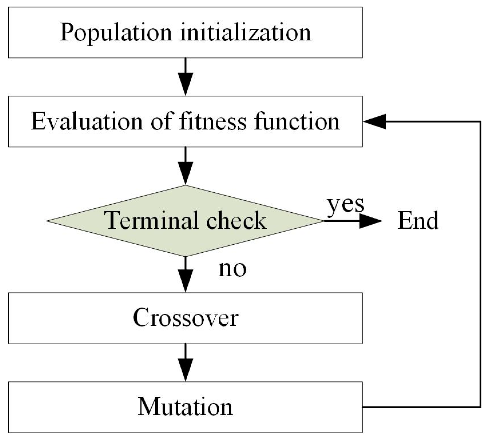
2.1.3. GA
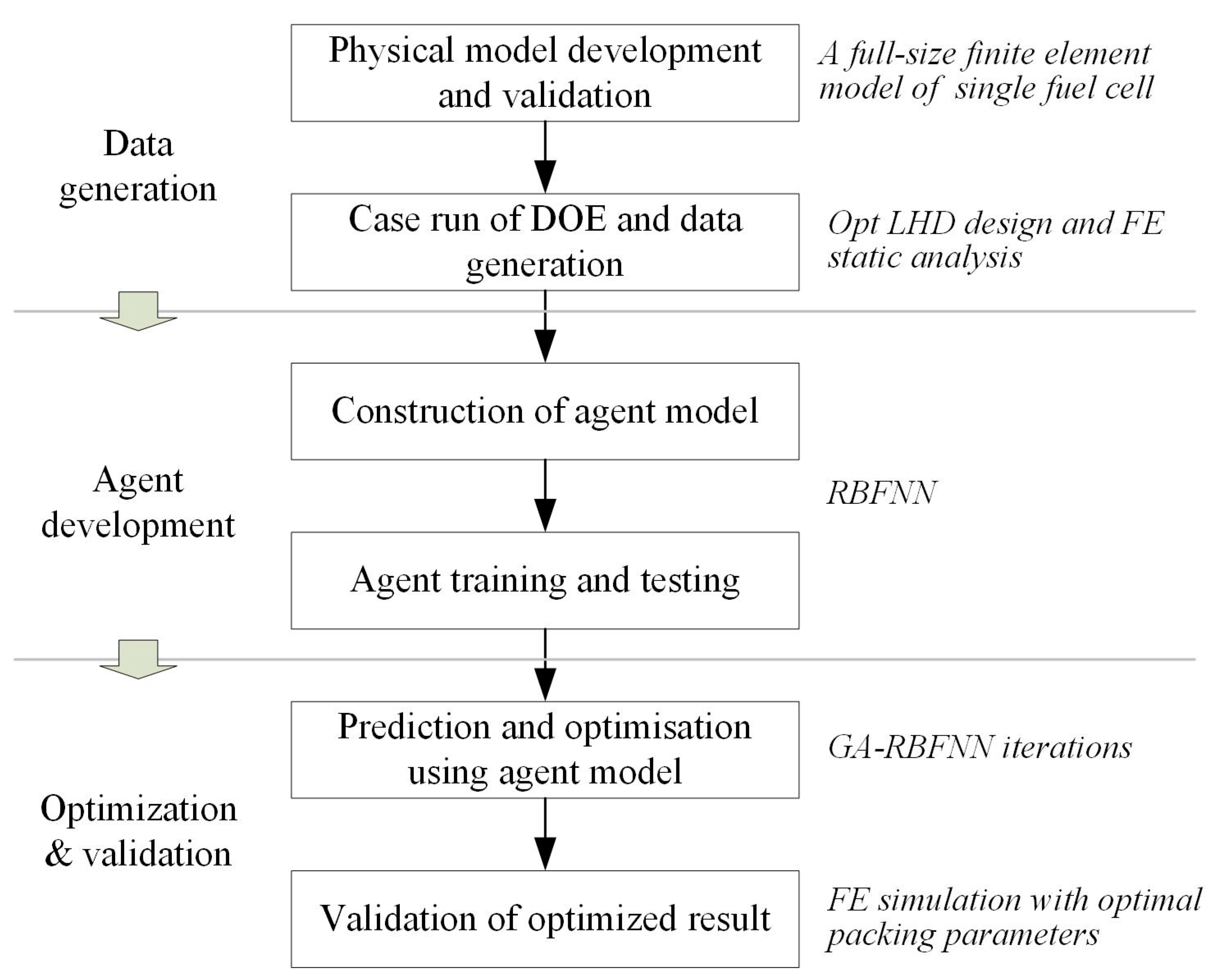
2.2. Objective and Workflow
3. Physical Model
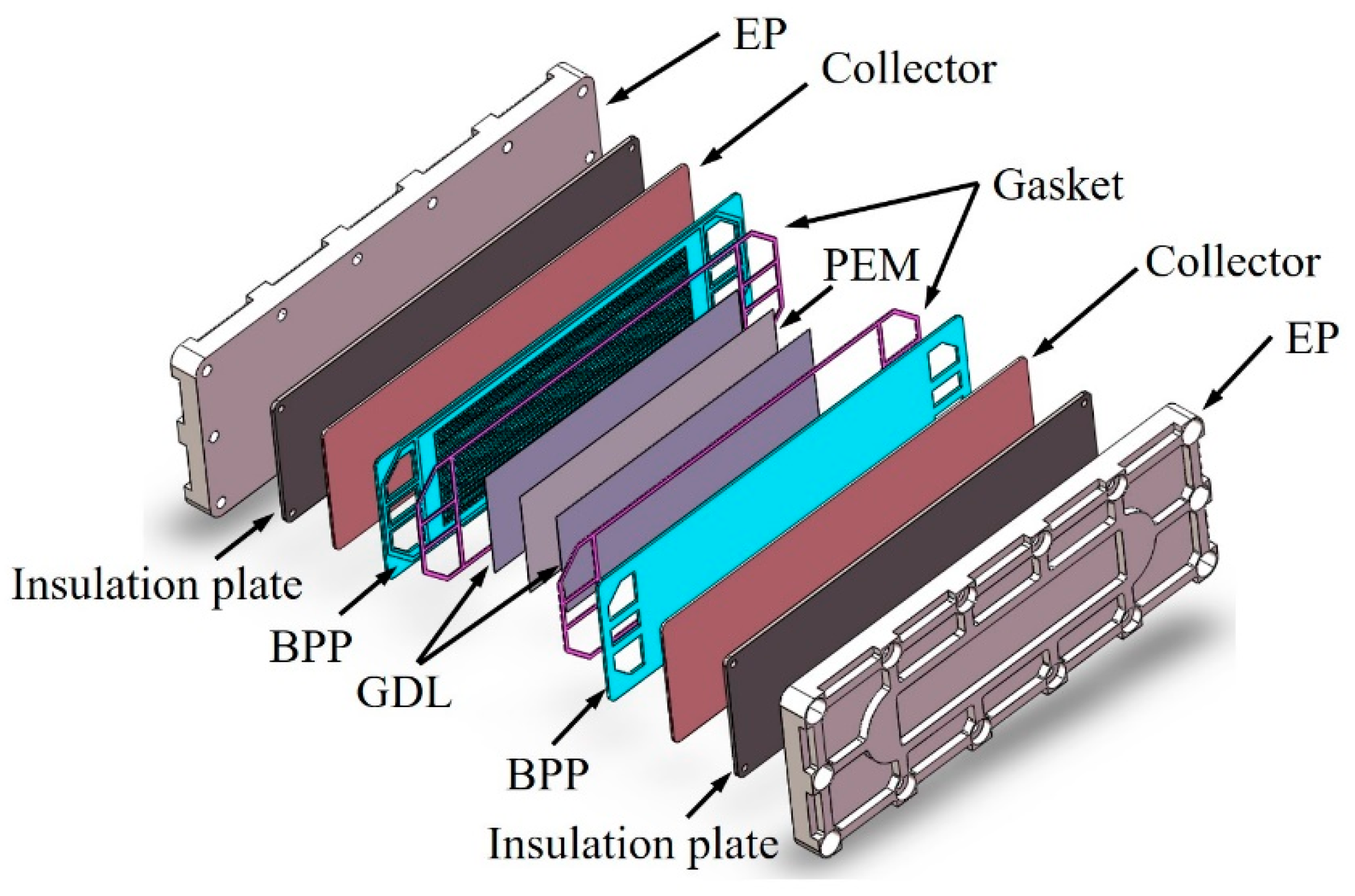
3.1. Geometry
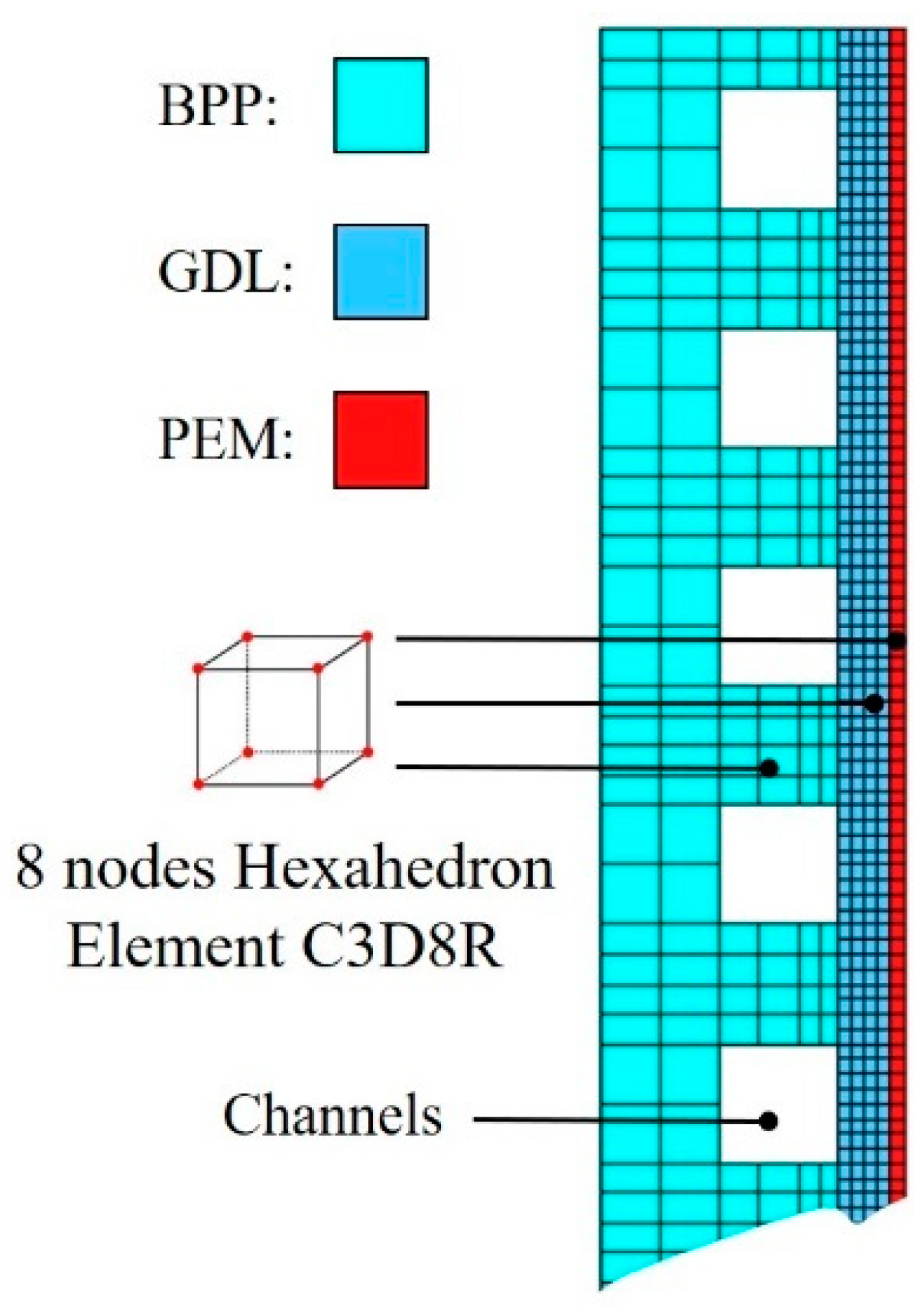
3.2. Meshing
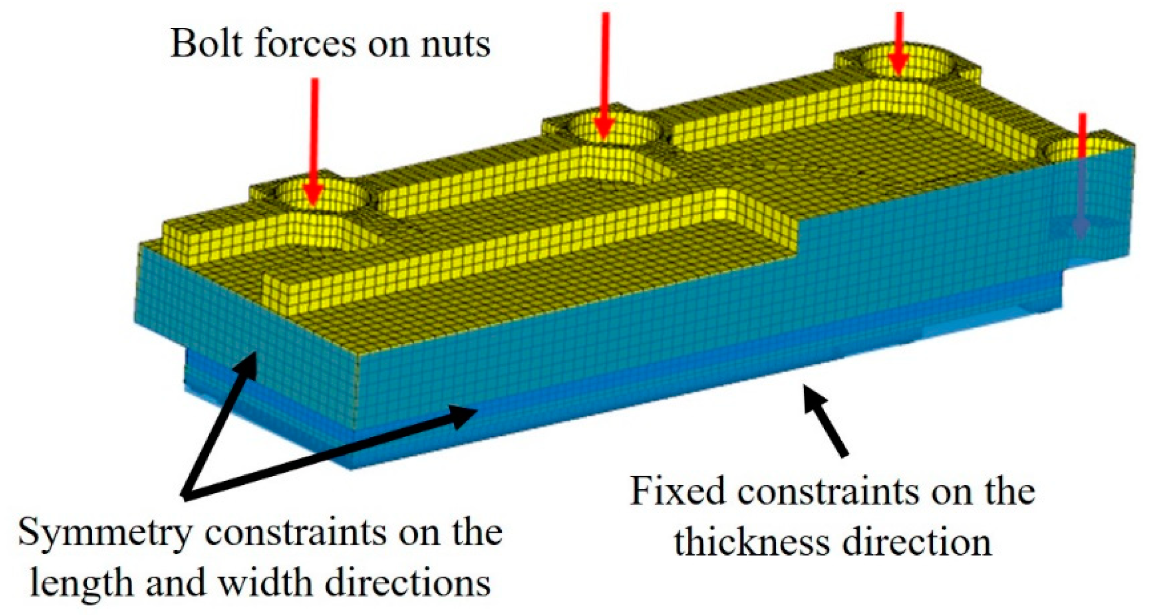
3.3. Boundary and Loading Conditions
3.4. Material Properties
4. Results and Discussion
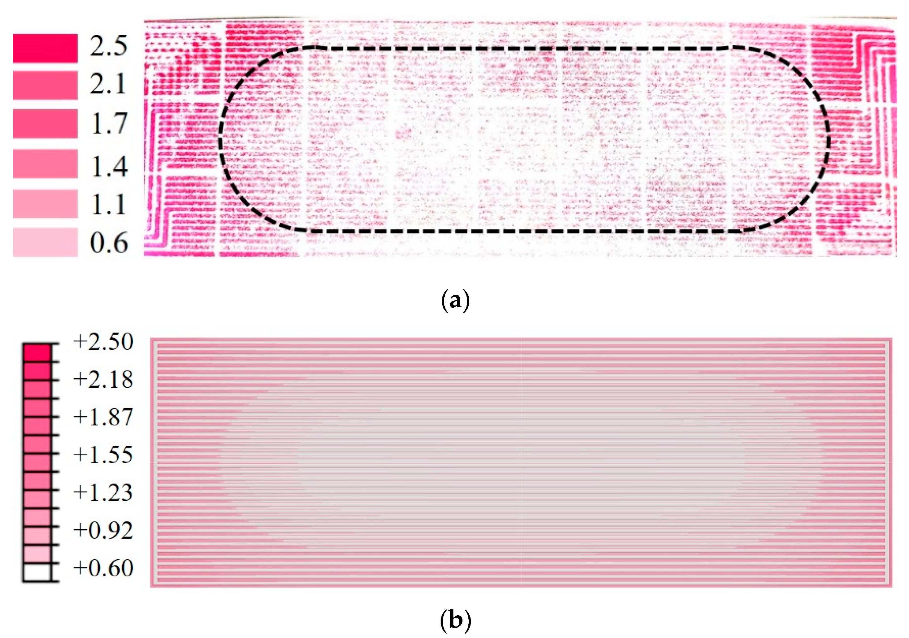
4.1. FE Model Validation
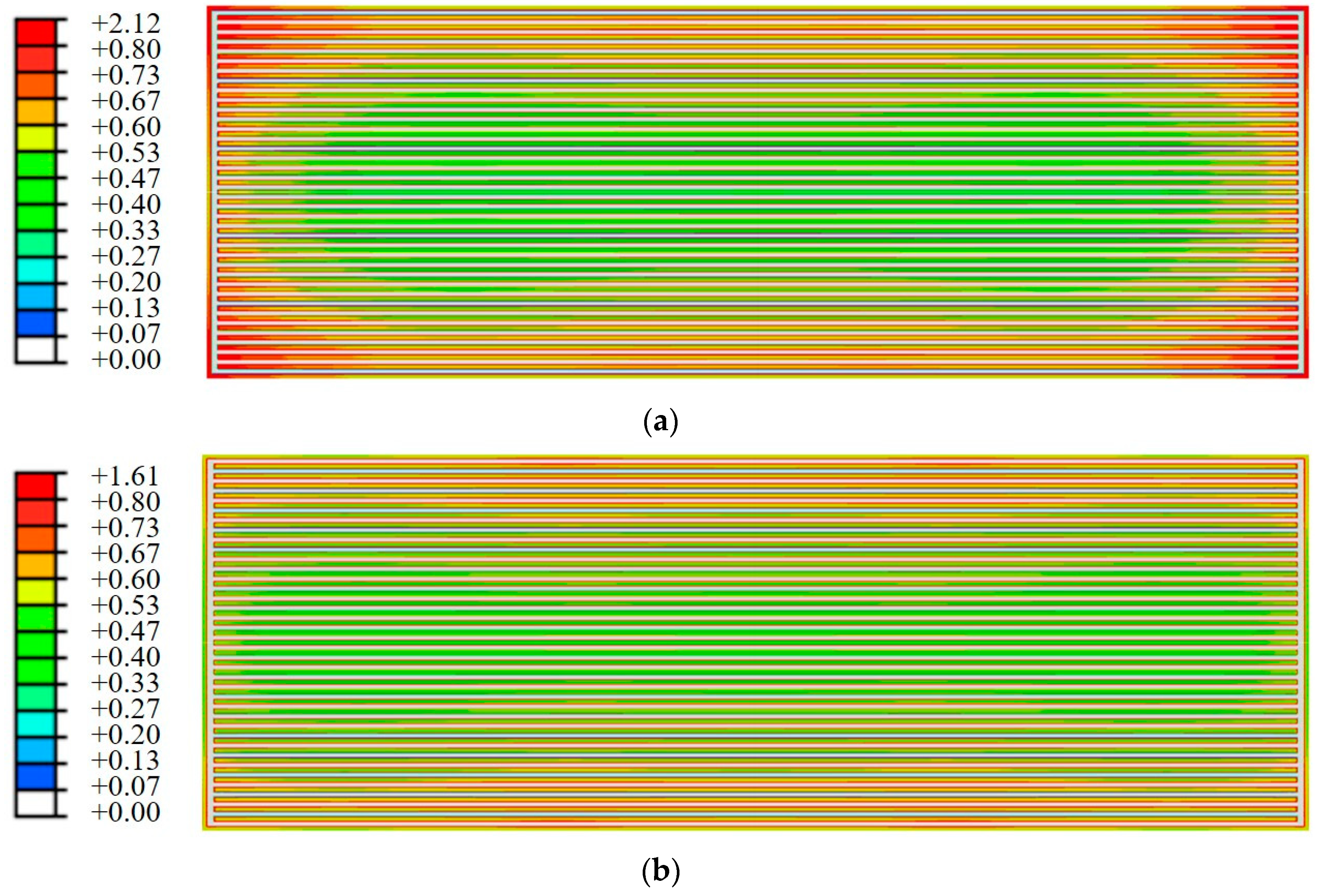
4.2. Distribution of Contact Pressure
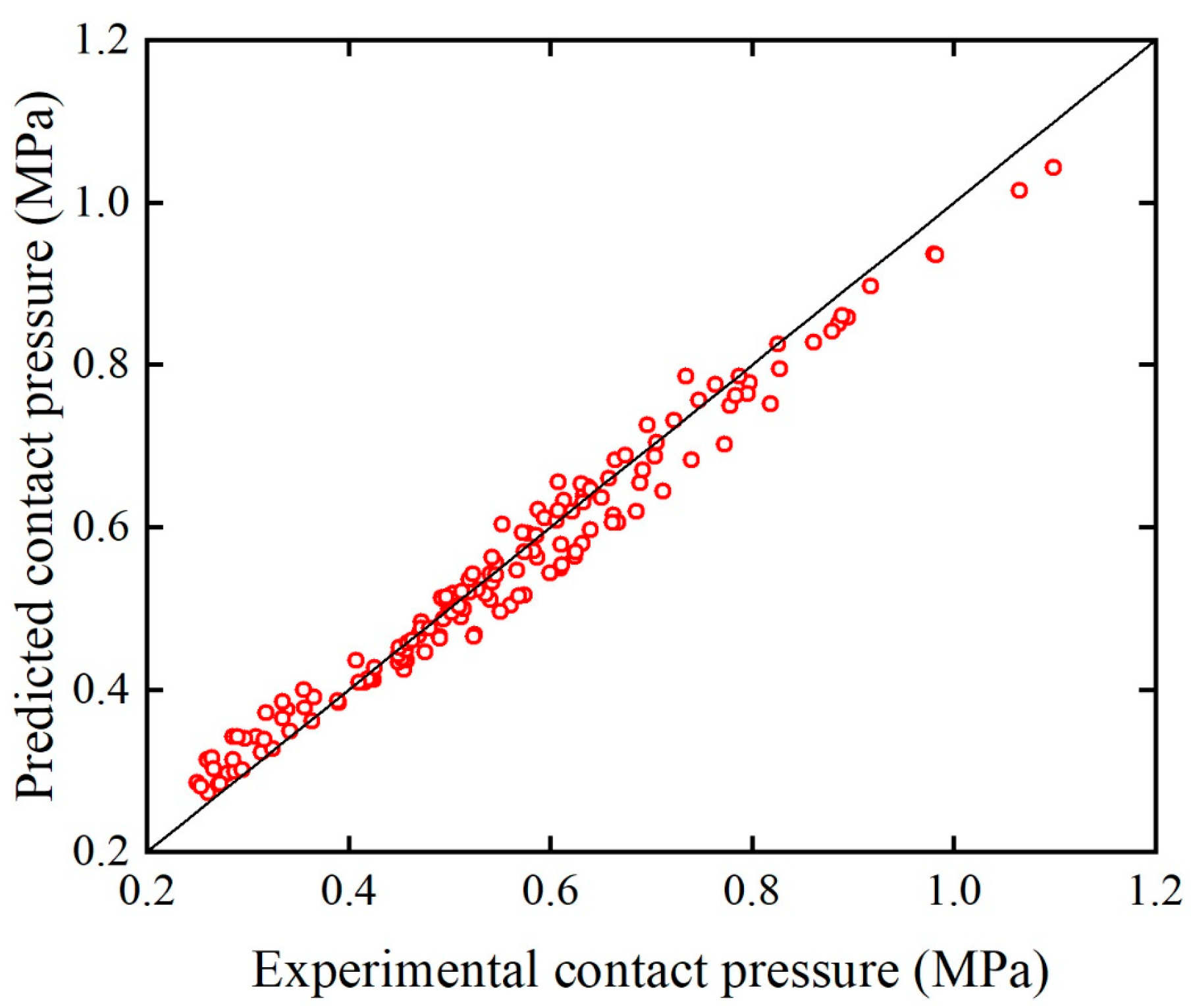
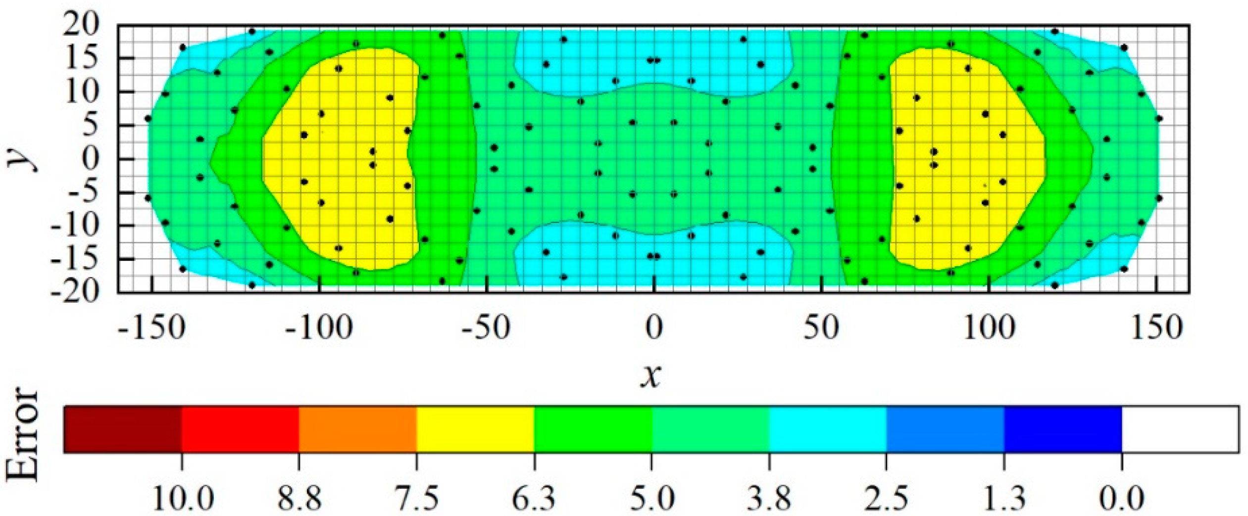
4.3. Agent Model Performance
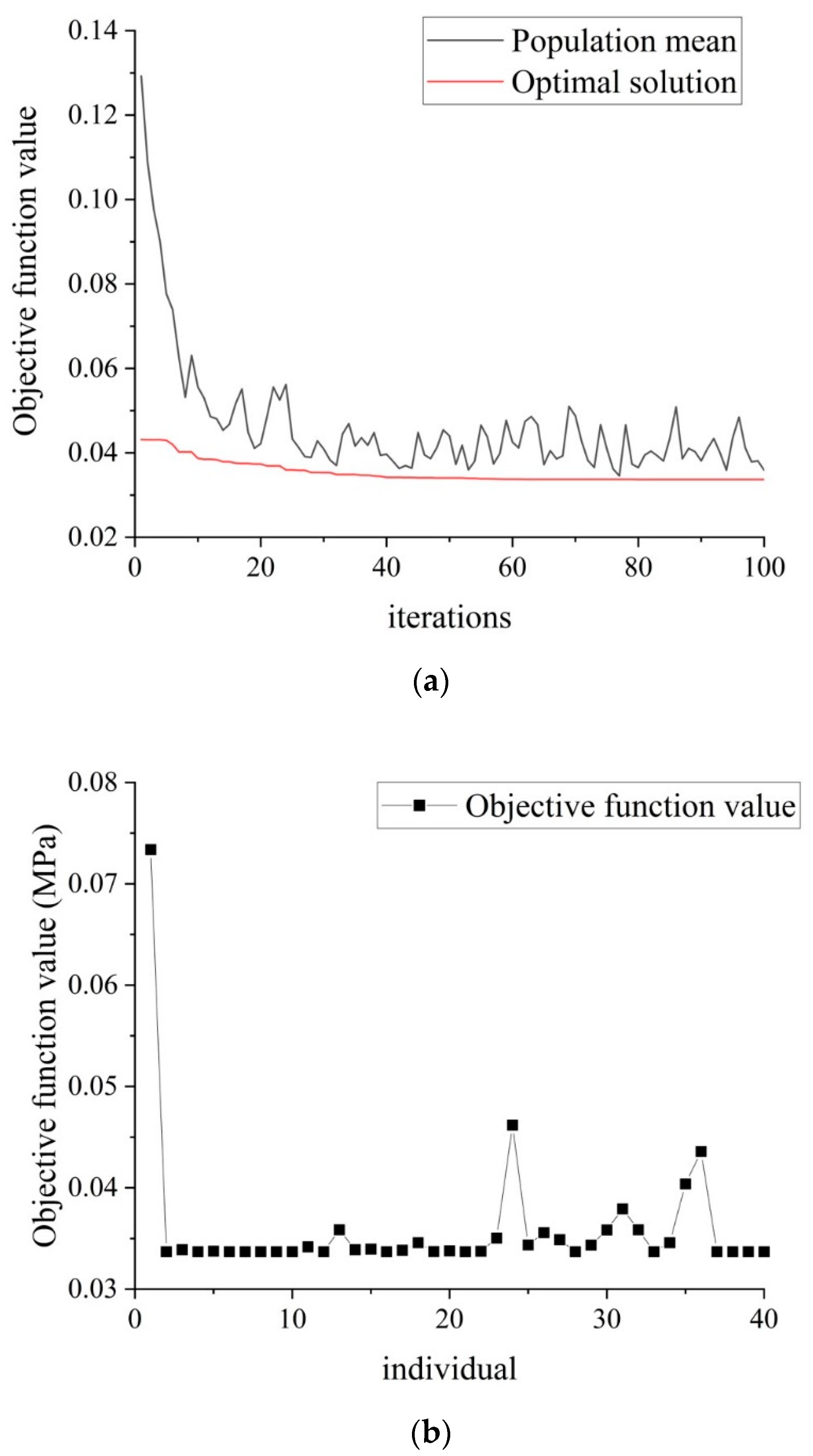
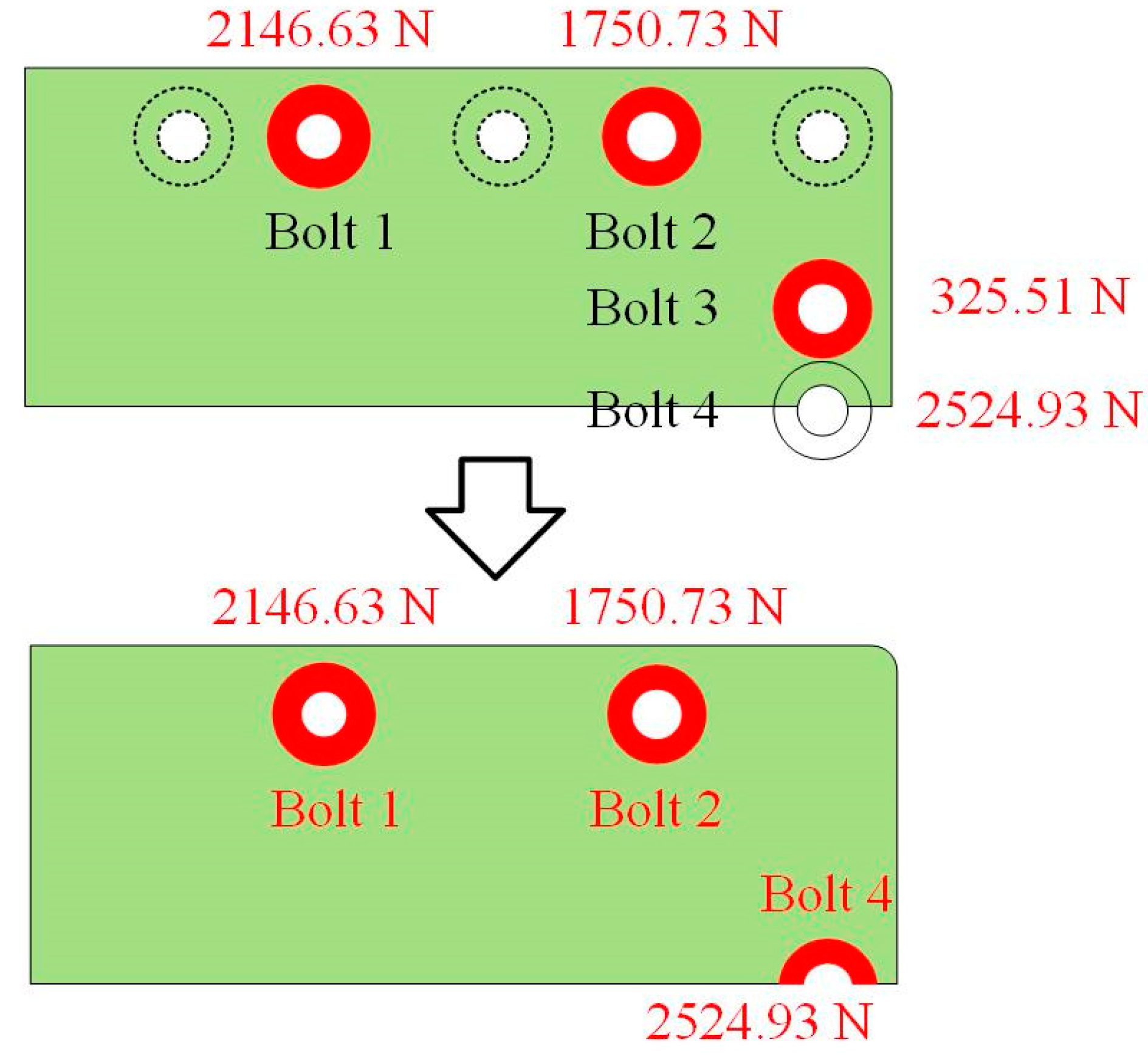
4.4. Optimization of Packing
5. Conclusions
Author Contributions
Acknowledgments
Conflicts of Interest
References
- Movahedi, M.; Ramiar, A.; Ranjber, A.A. 3D numerical investigation of clamping pressure effect on the performance of proton exchange membrane fuel cell with interdigitated flow field. Energy 2018, 142, 617–632. [Google Scholar] [CrossRef]
- Xu, Y.; Qiu, D.; Yi, P.; Lan, S.; Peng, L. An integrated model of the water transport in nonuniform compressed gas diffusion layers for PEMFC. Int. J. Hydrogen Energy 2019, 44, 13777–13785. [Google Scholar] [CrossRef]
- Li, L.; Wang, S.; Wang, G.; Yue, L.; Takuto, A. Effect of clamping stress on Cold Start Performance of PEMFC. Energy Procedia 2019, 158, 1744–1749. [Google Scholar] [CrossRef]
- Zhou, Y.; Jiao, K.; Du, Q.; Yin, Y. Gas diffusion layer deformation and its effect on the transport characteristics and performance of proton exchange membrane fuel cell. Int. J. Hydrogen Energy 2013, 38, 12891–12903. [Google Scholar] [CrossRef]
- Lee, W.; Ho, C.; Van Zee, J.W.; Murthy, M. The effects of compression and gas diffusion layers on the performance of a PEM fuel cell. J. Power Sources 1999, 84, 45–51. [Google Scholar] [CrossRef]
- Ge, J.; Higier, A.; Liu, H. Effect of gas diffusion layer compression on PEM fuel cell performance. J. Power Sources 2006, 159, 922–927. [Google Scholar] [CrossRef]
- Chang, W.R.; Hwang, J.J.; Weng, F.B.; Chan, S.H. Effect of clamping pressure on the performance of a PEM fuel cell. J. Power Sources 2007, 166, 149–154. [Google Scholar] [CrossRef]
- Bazylak, A.; Sinton, D.; Liu, Z.S.; Djilali, N. Effect of compression on liquid water transport and microstructure of PEMFC gas diffusion layers. J. Power Sources 2007, 163, 784–792. [Google Scholar] [CrossRef]
- Cha, D.; Ahn, J.H.; Kim, H.S.; Kim, Y. Effects of clamping force on the water transport and performance of a PEM (proton electrolyte membrane) fuel cell with relative humidity and current density. Energy 2015, 93, 1338–1344. [Google Scholar] [CrossRef]
- Qiu, D.; Yi, P.; Peng, L.; Lai, X. Assembly design of proton exchange membrane fuel cell stack with stamped metallic bipolar plates. Int. J. Hydrogen Energy 2015, 40, 11559–11568. [Google Scholar] [CrossRef]
- Zhou, P.; Wu, C.W.; Ma, G.J. Influence of clamping force on the performance of PEMFCs. J. Power Sources 2007, 163, 874–881. [Google Scholar] [CrossRef]
- Xing, X.Q.; Lum, K.W.; Poh, H.J.; Wu, Y.L. Optimization of assembly clamping pressure on performance of proton-exchange membrane fuel cells. J. Power Sources 2010, 195, 62–68. [Google Scholar] [CrossRef]
- Peng, L.; Shao, H.; Qiu, D.; Yi, P.; Lai, X. Investigation of the non-uniform distribution of current density in commercial-size proton exchange membrane fuel cells. J. Power Sources 2020, 453, 227836. [Google Scholar] [CrossRef]
- Asghari, S.; Shahsamandi, M.H.; Ashraf Khorasani, M.R. Design and manufacturing of end plates of a 5kW PEM fuel cell. Int. J. Hydrogen Energy 2010, 35, 9291–9297. [Google Scholar] [CrossRef]
- Alizadeh, E.; Barzegari, M.M.; Momenifar, M.; Ghadimi, M.; Saadat, S.H.M. Investigation of contact pressure distribution over the active area of PEM fuel cell stack. Int. J. Hydrogen Energy 2016, 41, 3062–3071. [Google Scholar] [CrossRef]
- Alizadeh, E.; Ghadimi, M.; Barzegari, M.M.; Momenifar, M.; Saadat, S.H.M. Development of contact pressure distribution of PEM fuel cell’s MEA using novel clamping mechanism. Int. J. Hydrogen Energy 2017, 131, 92–97. [Google Scholar] [CrossRef]
- Wang, X.; Song, Y.; Zhang, B. Experimental study on clamping pressure distribution in PEM fuel cells. J. Power Sources 2008, 179, 305–309. [Google Scholar] [CrossRef]
- Yu, H.N.; Kim, S.S.; Suh, J.D.; Lee, D.G. Composite endplates with pre-curvature for PEMFC (polymer electrolyte membrane fuel cell. Compos. Struct. 2010, 92, 1498–1503. [Google Scholar] [CrossRef]
- Wang, B.; Zhang, G.; Wang, H.; Xuan, J.; Jiao, K. Multi-physics-resolved digital twin of proton exchange membrane fuel cells with a data-driven surrogate model. Energy AI 2020, 1, 100004. [Google Scholar] [CrossRef]
- Wang, B.; Xie, B.; Xuan, J.; Jiao, K. AI-based optimization of PEM fuel cell catalyst layers for maximum power density via data-driven surrogate modeling. Energy Convers. Manag. 2020, 205, 112460. [Google Scholar] [CrossRef]
- Zhang, J.; Wang, J.; Lin, J.; Guo, Q.; Chen, K.; Ma, L. Multiobjective optimization of injection molding process parameters based on Opt LHD, EBFNN, and MOPSO. Int. J. Adv. Manuf. Technol. 2016, 85, 2857–2872. [Google Scholar] [CrossRef]
- Bejan, A. AI and freedom for evolution in energy science. Energy AI 2020, 100001. Available online: https://www.researchgate.net/publication/340097977_AI_and_Freedom_for_Evolution_in_Energy_Science (accessed on 18 June 2020).
- Jin, D.; Ocone, R.; Jiao, K.; Xuan, J. Energy and AI. Energy AI 2020, 100002. Available online: https://researchportal.hw.ac.uk/en/publications/energy-and-ai (accessed on 18 June 2020).
- Krzywanski, J.; Fan, H.; Feng, Y.; Shaikh, A.R.; Fang, M.; Wang, Q. Genetic algorithms and neural networks in optimization of sorbent enhanced H2 production in FB and CFB gasifiers. Energy Convers. Manag. 2018, 171, 1651–1661. [Google Scholar] [CrossRef]
- Yan, Z.; He, A.; Hara, S.; Shikazono, N. Modeling of solid oxide fuel cell (SOFC) electrodes from fabrication to operation: Microstructure optimization via artificial neural networks and multi-objective genetic algorithms. Energy Convers. Manag. 2019, 198, 111916. [Google Scholar] [CrossRef]
- Zhao, J.; Ma, Y.; Zhang, Z.; Wang, S.; Wang, S. Optimization and matching for range-extenders of electric vehicles with artificial neural network and genetic algorithm. Energy Convers. Manag. 2019, 184, 709–725. [Google Scholar] [CrossRef]
- Krzywanski, J.; Grabowska, K.; Herman, F.; Pyrka, P.; Sosnowski, M.; Prauzner, T.; Nowak, W. Optimization of a three-bed adsorption chiller by genetic algorithms and neural networks. Energy Convers. Manag. 2017, 153, 313–322. [Google Scholar] [CrossRef]
- Zhang, J.; Guo, P.; Lin, J.; Wang, K. A mathematical model for coupled vibration system of road vehicle and coupling effect analysis. Appl. Math. Model. 2016, 40, 1199–1217. [Google Scholar] [CrossRef]
- Fernando, D.A.K.; Jayawardena, A.W. Runoff forecasting using RBF networks with OLS algorithm. J. Hydrol. Eng. 1998, 3, 203–209. [Google Scholar] [CrossRef]
- Houck, C.; Joines, J.; Kay, M. A Genetic Algorithm for Function Optimization: A MATLAB Implementation; NCSUIE-TR-95-09; North Carolina State University: Raleigh, NC, USA, 1998; Volume 22. [Google Scholar]
- Chien, C.; Hu, Y.; Su, T.; Liu, H.; Wang, C.; Yang, P.; Lu, Y. Effects of bolt pre-loading variations on performance of GDL in a bolted PEMFC by 3-D FEM analysis. Energy 2016, 113, 1174–1187. [Google Scholar] [CrossRef]
- Yan, M.; Liu, B.; Li, J. China Aeronautical Materials Handbook, 2nd ed.; China Standards Press: Beijing, China, 2002; Chapter 7; ISBN 7-5066-2665-9. [Google Scholar]


| Component | Material | Young’s Modulus (GPa) | Poisson’s Ratio |
|---|---|---|---|
| EP [31] | Steel | 200 | 0.3 |
| Insulation plate [32] | Epoxylite | 1 | 0.38 |
| Collector [31] | Copper | 110 | 0.34 |
| Gasket [32] | PTFE | 0.28 | 0.4 |
| BPP [31] | Graphite | 10 | 0.25 |
| GDL | - | 0.01 | 0.25 |
| PEM | - | 0.249 | 0.25 |
| Run | F1 | F2 | F3 | F4 | L1 | L2 | L3 |
|---|---|---|---|---|---|---|---|
| R1 | 76.9 | 2076.9 | 1923.1 | 2769.2 | 101.2 | 68.9 | 16.5 |
| R2 | 1153.8 | 1769.2 | 76.9 | 1692.3 | 120.3 | 42.4 | 36 |
| R3 | 1692.3 | 1307.7 | 1230.8 | 2615.4 | 123.7 | 72.4 | −17 |
| … | … | … | … | … | … | … | … |
| R80 | 1307.7 | 615.4 | 2076.9 | 2461.5 | 92.1 | 52.8 | 35 |
© 2020 by the authors. Licensee MDPI, Basel, Switzerland. This article is an open access article distributed under the terms and conditions of the Creative Commons Attribution (CC BY) license (http://creativecommons.org/licenses/by/4.0/).
Share and Cite
Qiu, Y.; Wu, P.; Miao, T.; Liang, J.; Jiao, K.; Li, T.; Lin, J.; Zhang, J. An Intelligent Approach for Contact Pressure Optimization of PEM Fuel Cell Gas Diffusion Layers. Appl. Sci. 2020, 10, 4194. https://doi.org/10.3390/app10124194
Qiu Y, Wu P, Miao T, Liang J, Jiao K, Li T, Lin J, Zhang J. An Intelligent Approach for Contact Pressure Optimization of PEM Fuel Cell Gas Diffusion Layers. Applied Sciences. 2020; 10(12):4194. https://doi.org/10.3390/app10124194
Chicago/Turabian StyleQiu, Yongbo, Peng Wu, Tianwei Miao, Jinqiao Liang, Kui Jiao, Tao Li, Jiewei Lin, and Junhong Zhang. 2020. "An Intelligent Approach for Contact Pressure Optimization of PEM Fuel Cell Gas Diffusion Layers" Applied Sciences 10, no. 12: 4194. https://doi.org/10.3390/app10124194
APA StyleQiu, Y., Wu, P., Miao, T., Liang, J., Jiao, K., Li, T., Lin, J., & Zhang, J. (2020). An Intelligent Approach for Contact Pressure Optimization of PEM Fuel Cell Gas Diffusion Layers. Applied Sciences, 10(12), 4194. https://doi.org/10.3390/app10124194