Abstract
Micromachining in the micro-electric discharge machining (μ-EDM) process requires high material-removal rate with good surface quality. Power-mixed μ-EDM, a modified machining process by introducing specific powder into the dielectric fluid, is among the key inventions to achieving these requirements. This article presents a review of the implementation of powder-mixed micro-EDM processes for microfabrication. Special attention was given to the influence of the powder characteristics, such as the concentration, electrical conductivity, shape and size of the powder. Subsequently, when describing the use of powder for obtaining a high material-removal rate and surface quality, other major applications in μ-EDM for surface modification and geometrical accuracy were also discussed. Finally, some of the varied methods that are used in powder-mixed μ-EDM and industrialization challenges are extensively elaborated.
1. Introduction
Electrical discharge machining (EDM) is a process where spark erosion is used to fabricate a complex shape through an electrically conductive workpiece by using a tool electrode. The workpiece material is removed by thermal erosion process with repetitive spark discharges produced by pulsating DC power supply [1]. The main cause for material removal from the workpiece is the temperature above the melting points, which is generated in the discharge channel [2]. In the field of material science and engineering, compared to other machining processes, EDM has been widely used to fabricate difficult to machine materials [3,4,5,6]. This is due to the fact that EDM has good control in providing high surface quality and machining accuracy without sacrificing machining efficiency [7,8,9,10]. There are challenges for developing the device in the field of biomedical and automotive industries, which is the miniaturization of the system [11,12,13]. In order to answer these challenges, where a precise and an accurate fabricating process is necessary, a smaller scale of EDM, known as micro-electrical discharge machining (μ-EDM) becomes the solution [14,15,16]. Other non-conventional fabricating processes, such as wet etching and electropolishing, are incapable of providing high-accuracy machining geometry, due to the difficulty in controlling chemical machining processes [17,18].
Having a machining process without any direct contact between the tool and the workpiece, μ-EDM is able to fabricate miniature parts without distorting the workpiece from any mechanical stress and machining vibrations [19,20,21]. Another capability of μ-EDM is its ability to process any electrically conductive materials regardless of their hardness by using melting and vaporization as a material removal mechanism [12,13,14,15,16,17,18,19,20,21,22,23,24,25,26,27]. The detail of material removal mechanism is illustrated in Figure 1 [28]. Therefore, μ-EDM is considered as an effective method to machine high aspect ratio microholes and 3D cavities [29].
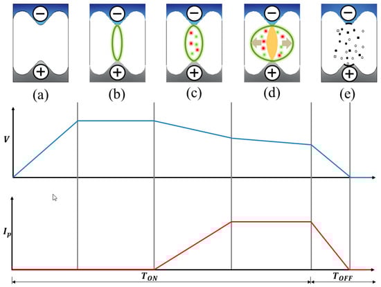
Figure 1.
Mechanism of the material-removal rate in electrical discharge machining (EDM): (a) the pre-ignition phase; (b) the ignition phase; (c) the plasma formation; (d) the discharge phase; and (e) the ejection phase.
In recent years, researchers have been developing a method to improve the performance and machining efficiency of μ-EDM [30,31]. Some of these methods are utilizing high electric resistance electrodes, vibration-assisted μ-EDM and the utilization of powder-mixed dielectric in μ-EDM.
The utilization of powder-mixed dielectric in EDM started in 1980 [26]. Semi-conductive powder was introduced into the dielectric fluid to improve the material-removal rate and surface quality of the workpiece machining [32,33]. Figure 2 explains the mechanism of powder-mixed EDM. The same method was applied to μ-EDM processes, which has similar characteristics to that of EDM [28,34]. However, there are some differences between the two in terms of the size of tool electrodes and discharge energy [35]. The differences yield different effects, where a certain powder size which gave optimum results in EDM may not provide the same result in μ-EDM. In addition, the introduction of powder in μ-EDM requires a full understanding of the mechanism and the machining performance of the powder based on their mechanical properties.
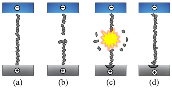
Figure 2.
Mechanism of powder-mixed EDM: (a) the bridge formation; (b) the spark initiation of because of the breakage of chain; (c) the explosion leading to zigzag particle motion and (d) the re-bridging.
This paper presents a comprehensive and critical review of micromachining carried out by powder-mixed μ-EDM. The focus was given on the mechanism of powder-mixed μ-EDM and the impact of powder properties to the machining removal rate, surface quality and surface modification. The variation of the powder-mixed μ-EDM process, current status, future perspectives and the potential of powder-mixed μ-EDM are also discussed.
2. Micro-EDM (μ-EDM)
The machining mechanism of that in μ-EDM is similar to the EDM process. During the machining process, unwanted material is removed by rapid sparking between the tool and the workpiece, which are separated by dielectric fluid to provide insulation. As the tool electrode is approaching the workpiece, the intensity of the electric field is increasing, and at some point it becomes higher than the dielectric strength, resulting in the generation of sparks between the electrodes [36]. To achieve small material removal, in μ-EDM, discharge energy per single pulse is reduced. Since there is no physical contact between the tool and the workpiece, followed by the characteristic of low-discharge energy, the machining force of μ-EDM can be ignored [37]. The resistor-capacitor (RC)-type pulse generator is preferred in μ-EDM because it is easy to have a pulse with a short discharge duration to produce high-quality microholes and better dimensional accuracy, which becomes an important factor in micromachining [38,39,40]. However, due to arcing caused by normal pulse discharge and insufficient pure dielectric deionization [41], a modified machining process by introducing specific powder to the dielectric fluid, which is known as powder-mixed μ-EDM, was conducted.
Unlike the conventional EDM processes, power-mixed μ-EDM utilizes a semi-conductive material in the form of powder which is mixed into the dielectric liquid. The added powder can organize themselves into series of bridges between the tool electrode and workpiece [42]. The conductivity of the powder decreases the insulating strength of the dielectric fluid, which gives an early breakdown in the gap [43]. Figure 3 shows the difference between conventional EDM and power-mixed μ-EDM. The dispersion of powder in the machining gap contributes in a series of discharges to improve the material-removal rate without degrading the surface quality.
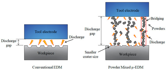
Figure 3.
Illustration of conventional EDM and power-mixed micro-electric discharge machining (μ-EDM).
This paper divides the research and development of power-mixed μ-EDM into four sections: powder characteristics, applications of power-mixed micro-electric discharge machining (PM μ-EDM), the variations of PM μ-EDM and the challenges of PM μ-EDM, as shown in Figure 4.
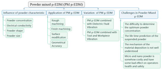
Figure 4.
Research and development of power-mixed μ-EDM.
3. Influence of Powder Characteristics
It has been reported that powder concentration, powder shape, powder size and electrical conductivity all highly contribute in defining the finished surface and material-removal rate of power-mixed μ-EDM process.
3.1. Powder Concentration
Wang and Qiang [36] found that material-removal rate increases with the increase in powder concentration. In this experiment, copper was used as the tool electrode and Inconel 706 was selected as a workpiece material. Al powder was used as an additive in EDM oil in a concentration range of 0–40 g/L. They found that the material-removal rate increases with the increase of powder concentration, in this case at a concentration of 15 g/L. However, at a higher concentration—more than 15 g/L—the removal rate will decrease. This is due to the excessive powder deposited near the machining area. Instead of assisting electrical sparks to spread, excessive powder creates difficulty in removing the debris, and hence interrupts the machining cycle. Sivaprkasam et al. [44] and Yılmaz et al. [45] investigated that the material-removal rate and the quality of the surface machined was significantly increased with the introduction of graphite nanopowder. The suspended nano graphite powder breaks single sparks into many, small, uniform sparks to produce craters on the surface of the workpiece machine, resulting in the reduction of surface roughness.
Liew et al. [46] studied the effect of added carbon nanofibre into dielectric fluid in the material migration between tool electrode (tungsten) and workpiece (reaction-bonded silicon carbide). The result showed that it is necessary to introduce nanofibre at a concentration of 0.06 g/L in order to improve the surface quality and to prevent the deposition of tungsten material onto the workpiece surface. This can be explained by the fact that the nanofibre in the dielectric fluid initiated smaller discharge to form smaller craters, and that the smaller craters were an obstacle for tungsten debris to deposit on the crater surface. In terms of the effect of powder concentration on the tool wear rate, Cyril et al. [47] added graphite powder into dielectric fluid at concentrations of 0 g/L, 2 g/L and 4 g/L. They found that as the concentration of graphite powder increased, the sparking gap between the tool electrode and the workpiece increased. This phenomenon enhances flushing the debris out of the working area and enables a stable machining process, which further leads to the decrease in tool wear rate. The lowest tool wear rate was obtained at a concentration of 4 g/L.
3.2. Electrical Conductivity
Tiwary et al. [48] compared three different types of powder in studying the effect of electrical conductivity on improving material-removal rate. They found that between Cu and Ni, Cu powder obtained the highest material-removal rate due to its superior electrical conductivity in improving the electrical energy distribution in the machining area.
Jahan et al. [49] studied how to improve the surface quality of tungsten carbide by introducing graphite, aluminum and alumina nanopowder-mixed dielectric. Based on the experiment results, semi-conductive graphite powder obtained a smooth and the lowest Ra and Rmax. On the other hand, conductive aluminum powder was proven to contribute to higher spark gap and material-removal rate. It was also revealed that non-conductive alumina has no significant contribution to improving the surface quality of tungsten carbide.
Chow et al. [50] presented that either Al or SiC powder-mixed dielectric fluid increased the material-removal depth and surface quality. The result shows that Al powder provides the largest sparking gap due to its optimal conductivity.
3.3. Powder Shape
While most of the studies used nanopowder in their experiments, Liew et al. [51] utilized carbon nanofibres with 150 nm in diameter and 6-8 μm lengths. They used a tungsten rod as the tool electrode and reaction-bonded silicon carbide (RB-SiC) for the workpiece material. The machining process was carried out at 110 V of voltage and 330 pF of condenser capacitance. The advantage of using carbon nanofibres instead of powders is that they have a better form of micro-chains interlock due to the nano size of fiber diameters and micron size in lengths, which assist to form better bridging networks between the tool electrode and the workpiece. The experiment results show that in pure dielectric condition, the material-removal rate is very low, around 0.0001 mm3/min. However, when the carbon nanofibers were introduced at a concentration of 0.17 g/L into the dielectric fluid, the maximum material-removal rate reached 0.0035 mm3/min. This achievement demonstrates that the frequency of discharge is increased with the introduction of carbon nanofibers into dielectric fluid. Moreover, the presence of carbon nanofibers in the dielectric fluid will also initiate the uniform dispersion of discharge energy, hence generating smaller crater sizes, resulting in the improvement of surface roughness (about 0.2 µm) compared to the one in pure dielectric fluid (about 0.4 µm), as shown in Figure 5.
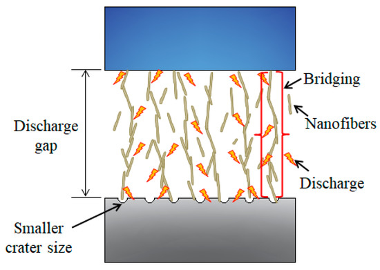
Figure 5.
Schematic model for carbon nanofiber assisted μ-EDM.
3.4. Powder Size
Prihandana et al. [52] observed the introduction of molybdenum disulfide (MoS2) powder at sizes 2 μm, 50 nm and 10 nm in the dielectric fluid, respectively. They found that at a powder concentration of 5 g/L, MoS2 with 50 nm size produced a better surface quality of microholes in Inconel 718, without leaving any black traces or cones in the center of the hole. Furthermore, compared to the other powder sizes (10 nm and 2 μm), 50 nm MoS2 powder was the best size to achieve the highest material-removal rate. An insignificant impact in material-removal rate was provided by the 10 nm MoS2 powder, whilst the 2 μm MoS2 powder was not suitable for μ-EDM due to the discharge gap distance in the conventional μ-EDM being only in the range of a few microns [53]. Figure 6 and Figure 7 summarize the influence of powder properties on enhancing material-removal rate and the surface quality of the machined workpiece.
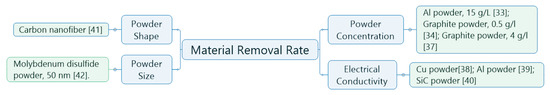
Figure 6.
Summary of the effect of powder property on material-removal rate.
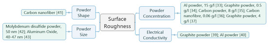
Figure 7.
Summary of the effect of powder properties on surface roughness.
4. Application of Power-mixed μ-EDM (PM μ-EDM)
4.1. Application of PM μ-EDM in Rough Machining
Rough machining is identical to high material-removal rate. In this case, powder was used to obtain a high material-removal rate and the surface quality of the machined workpiece was sometimes neglected. Chow et al. [54] observed the suspension of SiC powder in pure water for a titanium (Ti) alloy in micro-slit EDM. The results show that the SiC powder in pure water could disperse the discharging energy that effectively improved the surface quality, whilst at the same time achieved a high material-removal rate. Kuriachen et al. [55] conducted an experiment by adding SiC powder into dielectric on Ti-6Al-4V. The results show that in order to achieve the maximum material-removal rate, a low-powder concentration, which is 5 g/L, capacitance of 0.1 µF and voltage of 115 V, needs to be used as the machining parameters.
Pillai et al. [56] reported an improvement of material-removal rate of up to 13 times by using graphene nanopowder. The addition of graphene nanopowder increases the quantity of charges accumulated in the shallow entrapment zone around the nanopowder. However, higher material-removal rates tend to generate higher tool wear rates, therefore upon the machining process they cryogenically treated the tool to improve the tool life.
4.2. Application of PMμ-EDM in Finish Machining
In μ-EDM, the surface of the machined workpiece requires further treatment to obtain the desired surface quality. However, it is arduous to have good surface quality on a complex microstructure, therefore micromachining in μ-EDM utilizes suspended powder to attain higher surface quality.
Wang et al. [36] was able to improve the surface quality of Inconel 706 up to 25.9% by adding Al powder into dielectric fluid at a concentration of 10 g/L. The introduction of Al powder into dielectric fluid generates the extension of the machining gap during the process, resulting in a less irregular deposition of debris, microholes and crater marks.
Finish machining at a higher material-removal rate can also be achieved by mixing boron carbide into de-ionized water [57]. The presence of carbide powder aids in building uniform and intense discharge in the machining gap, which significantly augments the unit-removal rate with less amount of recast layer on the surface machined.
Tan et al. [53] added SiC and Al nanopowders into dielectric fluid and had an average of 14%–24% reduction of the surface roughness. The additional advantage of introducing the powder is keeping the geometrical accuracy shape produced. Yeo et al. [58] utilized SiC nanopowder in order to have a better surface quality. The presence of nanopowder in dielectric fluid promotes a reduction of thermal energy generation; hence smaller diameter of craters and a larger amount of re-solidified materials are produced.
Wu et al. [59] fabricated a 3D microstructure by using deionized water containing B4C powder. Reciprocating powder-mixed μ-EDM with a laminated 3D microelectrode method was suitable for the fabrication of a 3D microstructure with high accuracy. The polishing properties of B4C on the microelectrode and microstructure provides smooth material removal and guarantees an efficient and stable machining process. Jahan et al. [60] investigated the feasibility of improving the surface properties of carbide in fine-finish and milling μ-EDM graphite-nanopowder-mixed dielectric fluid. The introduction of semi-conductive graphite nanopowder within dielectric fluid leads to a uniform distribution of sparking among powder particles to produce shallower craters for better distribution, resulting in a smooth and glossy surface finish.
4.3. Application of PMμ-EDM in Surface Modification
Applications of powder-mixed dielectric fluid μ-EDM are not only limited to obtaining high surface quality and material-removal rates. Powder material such as silver has anti-bacterial property, as well as high electrical conductivity [61,62], which is compatible as surfactant in the dielectric fluid. Viet et al. [63] utilized silver nanopowder to machine and to modify the surface of Ti-6Al-4V for improving its antibacterial property in medical applications. The results show that the deposited silver content increases with the increase in the powder concentration, however, at similar concentrations of powder, it decreases with the increase in pulse energy. Therefore, it is recommended to have a pulse energy lower than 17.5 μJ to achieve the surface requirement of having a antibacterial properties.
In order to improve the hard and wear resistance properties of an engine part, solid lubricating powders such as MoS2 have received more special attention than other materials [64]. Mohanty et al. [65] utilized MoS2 powder-mixed deionized water to generate a hard, wear-resistant and lubricating layer on titanium surface. The experiment results showed that the microhardness of titanium surface increased significantly up to two times more than the microhardness of base metal. This is due to the formation of an intermediate phase of titanium with molybdenum disulfide and oxides. In addition, the coefficient of friction of the modified surface decreased from 0.47 to 0.13. It can be concluded that a hard, self-lubricating and wear-resistant coated layer of MoS2 was deposited over the titanium surface through a powder-mixed dielectric μ-EDM process.
In biomedical application, powder-mixed dielectric μ-EDM was used to improve the hydrophilicity of the titanium surface, since a high-hydrophilicity surface is essential for dental implants as well as other biomedical applications [66,67,68,69]. Chen et al. [70] added pure Ti powders (35–45 μm in diameter) into the deionized water at concentrations of 3 g/L and 6 g/L. Pure Ti grade 4 was used as a tool electrode and the workpiece material. Hydrophilicity examination was performed by using the sessile drop method and a contact angle goniometer. The results showed that under conventional μ-EDM process, the water contact angle of the surface was found around 87°. When the powder was introduced into the fluid, the surface exhibited an improvement of hydrophilicity surface, which was around 65°. This can be explained that the introduction of titanium powder into dielectric fluid provides a thicker recast layer with a high content of TiO on the surface, resulting in the improvement of surface hydrophilicity.
Mohanty et al. [71] investigated the effect of using tungsten disulphide (WS2) powder-mixed dielectric fluid μ-EDM for the surface modification of Ti-6Al-4V. The material from the tool and the suspended powder from dielectric fluid migrated to the workpiece due to the generated high thermal energy from electrical sparks. Among other parameters, such as voltage and duty factor, the concentration of suspended WS2 was the most significant parameter affecting the deposition rate, surface roughness and the microhardness. The average microhardness value was improved up to three times from the original hardness value. Sharma et al. [72] obtained a coated surface with solid lubrication, hard and corrosion resistance on Ti6Al4V by mixing BN powder into a dielectric fluid of μ-EDM. Due to the presence of the BN, TiN dan TiAlN on the coated surface, the average microhardness improved from 280 HV (parent material) to in the range of 390.1 ± 6.2–1393.5 ± 7 HV. The wear test showed that the wear rate was significantly improved from 0.22 mg/min to 0.05 mg/min. The friction test also showed a great improvement of the coefficient of friction (CoF) from 0.4 to 0.26.
4.4. Application of PMμ-EDM in Geometrical Accuracy
Another objective of powder-mixed dielectric fluid in μ-EDM is to acquire a higher dimensional accuracy of the produced microparts, which plays an important role in microfabrication. Kibria et al. [73] performed microhole machining on a Ti-6Al-4V plate by utilizing different types of dielectric fluids, i.e., hydrocarbon oil, kerosene and non-hydrocarbon oil, de-ionized water mixed with B4C powder. The cylindrical tungsten of 300 µm in diameter was used as the tool electrode. Peak current and pulse-on-time, which are the most significant process parameters in micro-EDM processes, were varied from 0.5 A to 2.0 A and from 1 to 20 µs, respectively. This study concentrated on the accuracy of the microholes taper and circularity produced under different types of dielectric fluid. The result revealed that at low-discharge energies, it was found that the taper of microholes was lower under pure kerosene compared to the result under B4C powder-mixed kerosene. This is due to the stronger adhesion of carbon on the workpiece created by the presence of B4C in dielectric fluid, resulting in lower material removed from the exit of microholes. Thus, there is a significant difference of diameter at the entry and exit holes. In terms of circularity, machining under B4C powder-mixed dielectric fluid provided non-uniform microholes compared to pure dielectric fluid. This was due to the presence of debris from the workpiece and B4C powders. The debris created secondary discharges to produce a non-uniformly circular microholes.
Tiwary et al. [74] investigated μ-EDM machining of Ti-6Al-4V for microhole fabrication by using three different types of dielectric fluids, such as DEF-92 (EDM oil), deionized water and Cu powder-mixed deionized water at a concentration of 2 g/L. A cylindrical brass of diameter 300 μm was used as the tool electrode. The machining parameters considered in this EDM process were peak current at the range of 0.5–2 A and a pulse time of 8 µs. The works focused on the influence of Cu powder-mixed dielectric fluid to the circularity, over cut and taper, on microholes produced during the machining process of Ti6Al-4V. It was found that at the peak current range from 0.5 to 1.5 A, the taper under deionized water was less than the taper produced with Cu powder-mixed deionized water. However, when the peak current increased from 1.5 to 2 A, the machining in the Cu powder-mixed deionized water showed an improvement in the microholes taper. In the case of circularity, in the range of the peak current from 1.5–2 A, pure deionized water gave a better circularity than the Cu powder-mixed deionized water. At this peak current range, the pure deionized water dissipates heat better from the melted workpiece surface, which further reduces the adhesion of debris onto the machined surface.
Prihandana et al. [75] investigated the effect of suspended powder on the inaccuracy of the depth of microholes produced. In a μ-EDM process, the occurrence of first discharge, which becomes the starting point for the machining processes, is considered as the surface of the workpiece. Due to the presence of powder in the machining gap, the first discharge commences far above the surface of the workpiece. Therefore, the depth of the microholes produced was not accurate. In order to improve the accuracy of the microhole depth, the powder-mixed dielectric in the μ-EDM process was assisted by the discharge pulse-counting method. Instead of setting the hole’s depth in the numerical control (NC) code display, micromachining was performed by entering the number of discharges required in fabricating the blind microholes. The result showed that the combination of these two techniques significantly improved the accuracy of the microholes produced regardless of the concentration of the suspended powder. Figure 8 describes a simple graph to give a better understanding of the application of powder-mixed μ-EDM.
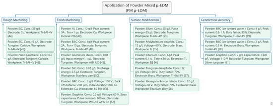
Figure 8.
Summary of the application of powder-mixed μ-EDM.
5. Variation of Power-mixed μ-EDM
5.1. Power-Mixed μ-EDM Combined with Dielectric Fluid Vibration
Among the problems of having powder in the dielectric fluid are the sedimentation and agglomeration of powder during the machining process. A stirrer is used to prevent powder deposition in the bottom of the dielectric fluid tank. However, this method was not efficient enough to prevent the agglomeration of the powder and to remove the debris from the machining area. Prihandana et al. [76] introduced micro-MoS2 powder and applied ultrasonic vibration in the dielectric fluid to improve the material-removal rate without sacrificing the surface quality, as illustrated in Figure 9. The Taguchi statistical method was employed to determine the optimal process parameters in having a high material-removal rate. Based on a Taguchi analysis, the ultrasonic vibration of dielectric fluid is essential in improving material-removal rate and the quality of the surface machined. The vibration in dielectric fluid at the ultrasonic level reduced the adhesion of the workpiece and prevented the agglomeration and deposition of MoS2 powder in the bottom of the tank.
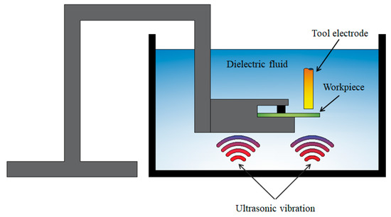
Figure 9.
Ultrasonic vibration of the dielectric assisted powder-mixed μ-EDM.
5.2. Power-Mixed μ-EDM Combined with Tool and Workpiece Vibration
The introduction of powder into the dielectric fluid has indeed improved the machining time [77] and surface quality. However, due to the presence of powder in the dielectric fluid which may induce short circuits, Liew et al. [78] used a probe-type vibrator to assist the fabrication of deep microholes of ceramic material during the μ-EDM machining process. The results showed that utilizing ultrasonic vibration only is insignificant to improve the depth of microholes. Thus, carbon nanofibers were added into the dielectric fluid to enhance the performance of μ-EDM in terms of material-removal rate, maximum machining depth, surface topography, hole geometry and process stability. Ultrasonic vibration enhances the stirring effect to uniformly distribute the carbon nanofibers and flush out the debris from the machining gap. Prihandana et al. [79] aided the workpiece vibration on nano graphite powder-mixed dielectric fluid of μ-EDM processes, as illustrated in Figure 10. Several powder concentrations (0 g/L, 5 g/L, 10 g/L, 15 g/L, 20 g/L) were used to investigate the effect of workpiece vibration in improving the performance of powder-mixed μ-EDM processes. The addition of powder at high concentrations may lead to unstable discharge and increase the occurrence of short-circuits during the machining process. The results showed that the highest machining time was achieved by combining workpiece vibration and nano graphite-powder-mixed dielectric fluid at concentration of 20 g/L. The improvement was due to workpiece vibration which reduced the arcing and short-circuiting caused by the excessive powder concentration.
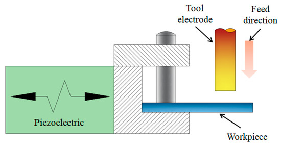
Figure 10.
Workpiece vibration-assisted-powder-mixed μ-EDM.
Finally, Figure 11 shows a simple illustration to improve the understanding of the variation of powder-mixed μ –EDM in machining processes.
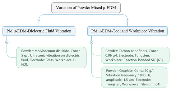
Figure 11.
Summary of the machining process variation of powder-mixed μ-EDM.
6. Challenges in Power-Mixed μ-EDM
The superiority of power-mixed μ-EDM in micromachining has been discussed in many researches, however, there is a number of problems that need to be solved for the industrialization of this modified process. These are summarized below:
- The difficulty in determining the optimum powder concentration for achieving high surface quality and material-removal rate. This is because the desired result does not only depend on powder type and concentrations but is also related to the machining parameters, such as capacitance, voltage, and pulse duration. Extensive studies in this area will be valuable to better understand the effect of a specific powder concentration to μ-EDM process;
- The lifetime prediction of the suspended powder. It is very difficult to measure the lifetime of the powder due to complex variables that affect each other in a unique way. Future studies need to focus on how long the powder will last for a specific machining process and materials;
- For the application of power-mixed μ-EDM in surface modification, due to the complexity of this process, the mechanism of the material deposition is not well understood, particularly in the context of powder melted and deposited onto the target. Therefore, comprehensive studies are required in this field;
- Micro and nanopowder is somehow costly and may have some bad effects on the operator’s health and safety. Thus, a thorough safety preparation is required to actualize this process into operation.
7. Conclusions
Micro-EDM is one of manufacturing processes to produce microparts with exceptional accuracy and precision. This article presented an extensive review of power-mixed μ-EDM to the machining efficiency, the application and its accuracy. The following conclusions are drawn based on the presented literature:
- There is an optimum powder concentration in power-mixed μ-EDM to achieve the best combination of the material-removal rate, the surface quality, and the tool wear rate. High powder concentration may lead to powder deposition around machining area, whilst low concentration may be insignificant to break single sparks into many small, uniform sparks to achieve a fine surface finish. Powder material with high electrical conductivity will contribute to a higher material-removal rate, whilst semi-conductive powder material provides a fine surface finish. The selection of powder material to be used depends highly on the machining stage (roughing, semi-finish or finishing).
- The machining gap in μ-EDM is only in the range of few microns, hence the selection of powder size should be in the range of 1/100–1/150 of the machining gap width to get the optimum machining result. Whilst circular nanopowder is mostly used in power-mixed μ-EDM, a cylindrical shape material with an aspect ratio of 40–50 yields will have a higher removal rate and improved surface roughness. Cylindrical shape material surpasses circular shape at the same concentration due to the bridge-forming of micro-length materials; thus, it promotes better bridging networks between the two electrodes.
- Rough machining requires high energy and often sacrifices the tool to have a high tool wear rate. Semi-conductive materials such as SiC are often used at low concentrations to achieve maximum material removal. Finish machining requires small energy to generate smaller craters, thus yielding a fine surface finish. The presence of nanopowder, either semi-conductive or in combination with other material, is able to break initial discharge into many, small discharges with less energy, hence allowing a fine surface finish by forming tiny craters.
- Surface modification in microparts can also be done in PM μ-EDM by utilizing specific powders for different usage, according to their biomedical, antibacterial, microhardness and wear-resistant properties. Exotic powder materials such as tungsten alloys, molybdenum and titanium alloys are often used for surface modification. The powder melts during spark-time and adheres to the workpiece, creating a thin layer on the top surface with different property than that in parent material.
- The μ-EDM machine detects the first spark as its starting point, which is incorrect since the added powder promotes a spark far above the workpiece surface. To overcome this problem, the depth of machining should not be set as depth but as counted discharge pulse. The combination of these techniques improved both the accuracy and the machining results.
- Powder sedimentation is another issue in power-mixed μ-EDM. Vibrating the dielectric fluid at the ultrasonic level is able to reduce adhesion, prevent powder agglomeration, and leads to improve material-removal rate and surface quality. The presence of powder makes short-circuiting and arcing prone to occur since the powder may connect the two electrodes before the discharge time. The introduction of tool vibration or workpiece vibration helps to better distribute the added powder in the tiny machining gap, and promotes the advanced flushing out of the debris, thus reducing arcing and short-circuiting.
Author Contributions
Conceptualization, G.S.P. and T.S.; methodology, G.S.P. and T.S.; resources, G.S.P., M.M., and T.S.; writing—original draft preparation, G.S.P; writing—review and editing, G.S.P. and T.S.; supervision, G.S.P., M.M., and T.S.; project administration, G.S.P.; funding acquisition, G.S.P. All authors have read and agreed to the published version of the manuscript.
Funding
This research was funded by Lembaga Penelitian dan Inovasi, Universitas Airlangga, Indonesia, under Article Review project.
Acknowledgments
The authors would like to thank staff of Lembaga Penelitian dan Inovasi, Universitas Airlangga, Indonesia, for the administrative support.
Conflicts of Interest
The authors declare no conflict of interest. The funders had no role in the design of the study; in the collection, analyses, or interpretation of data; in the writing of the manuscript, or in the decision to publish the results.
References
- Bahgat, M.; Shash, A.Y.; Abd-Rabou, M.; El-Mahallawi, I. Influence of process parameters in electrical discharge machining on H13 die steel. Heliyon 2019, 5, e01813. [Google Scholar] [CrossRef] [PubMed]
- Shahri, H.R.F.; Mahdavinejad, R.; Ashjaee, M.; Abdullah, A. A comparative investigation on temperature distribution in electric discharge machining process through analytical, numerical and experimental methods. Int. J. Mach. Tools Manuf. 2017, 114, 35–53. [Google Scholar] [CrossRef]
- Abidi, M.H.; Al-Ahamri, A.; Umer, U.; Rasheed, M.S. Multi-objective optimization of micro-electrical discharge machining of nickel-titanium-based shape memory alloy using MOGA-II. Measurement 2018, 125, 336–349. [Google Scholar] [CrossRef]
- Aliakbari, E.; Baseri, H. Optimization of machining parameters in rotary EDM process by using the Taguchi method. Int. J. Adv. Manuf. Technol. 2012, 62, 1041–1053. [Google Scholar] [CrossRef]
- Pandey, A.K.; Dubey, A. Multiple quality optimization in laser cutting of difficult-to-laser-cut material using grey–fuzzy methodology. Int. J. Adv. Manuf. Technol. 2012, 65, 421–431. [Google Scholar] [CrossRef]
- Xiao, X.; Zheng, K.; Liao, W. Theoretical model for cutting force in rotary ultrasonic milling of dental zirconia ceramics. Int. J. Adv. Manuf. Technol. 2014, 75, 1263–1277. [Google Scholar] [CrossRef]
- Jahan, M.P.; Rahman, M.; Wong, Y. A review on the conventional and micro-electrodischarge machining of tungsten carbide. Int. J. Mach. Tools Manuf. 2011, 51, 837–858. [Google Scholar] [CrossRef]
- Sriani, T.; Aoyama, H. Novel Tool Design Method for Orbiting EDM—A 2nd Approach on Design Automation Developed in CAD. J. Adv. Mech. Des. Syst. 2010, 4, 1261–1271. [Google Scholar] [CrossRef][Green Version]
- Sriani, T.; Nakamura, Y.; Aoyama, H. Novel Tool Design Method for Orbiting Electrical Discharge Machining. J. Adv. Mech. Des. Syst. 2010, 4, 1182–1191. [Google Scholar] [CrossRef]
- Dubey, A.K.; Yadava, V. Multi-objective optimization of Nd:YAG laser cutting of nickel-based superalloy sheet using orthogonal array with principal component analysis. Opt. Lasers Eng. 2008, 46, 124–132. [Google Scholar] [CrossRef]
- To, N.; Sanada, I.; Ito, H.; Prihandana, G.S.; Morita, S.; Kanno, Y.; Miki, N. Water-Permeable Dialysis Membranes for Multi-Layered Microdialysis System. Front. Bioeng. Biotechnol. 2015, 3, 1–7. [Google Scholar] [CrossRef] [PubMed]
- Ay, M.; Çaydaş, U.; Hasçalık, A. Optimization of micro-EDM drilling of inconel 718 superalloy. Int. J. Adv. Manuf. Technol. 2012, 66, 1015–1023. [Google Scholar] [CrossRef]
- Prihandana, G.S.; Ito, H.; Tanimura, K.; Yagi, H.; Hori, Y.; Soykan, O.; Sudo, R.; Miki, N. Solute diffusion through fibrotic tissue formed around protective cage system for implantable devices. J. Biomed. Mater. Res. Part B Appl. Biomater. 2014, 103, 1180–1187. [Google Scholar] [CrossRef] [PubMed]
- Mahardika, M.; Mitsui, K. A new method for monitoring micro-electric discharge machining processes. Int. J. Mach. Tools Manuf. 2008, 48, 446–458. [Google Scholar] [CrossRef]
- Liu, Q.; Zhang, Q.; Zhang, M.; Zhang, J. Review of size effects in micro electrical discharge machining. Precis. Eng. 2016, 44, 29–40. [Google Scholar] [CrossRef]
- Mahardika, M.; Prihandana, G.S.; Mitsui, K. Precision machining by discharge pulse counting methods in micro EDM processes. J. Mech. Sci. Technol. 2012, 26, 3597–3603. [Google Scholar] [CrossRef]
- Prihandana, G.S.; Mahardika, M.; Nishinaka, Y.; Ito, H.; Kanno, Y.; Miki, N. Electropolishing of Microchannels and its Application to Dialysis System. Procedia CIRP 2013, 5, 164–168. [Google Scholar] [CrossRef][Green Version]
- Gu, Y.; Miki, N. Multilayered microfilter using a nanoporous PES membrane and applicable as the dialyzer of a wearable artificial kidney. J. Micromech. Microeng. 2009, 19, 65031. [Google Scholar] [CrossRef]
- Jahan, M.P.; Wong, Y.; Rahman, M. A study on the fine-finish die-sinking micro-EDM of tungsten carbide using different electrode materials. J. Mater. Process. Technol. 2009, 209, 3956–3967. [Google Scholar] [CrossRef]
- Tiwary, A.P.; Pradhan, B.B.; Bhattacharyya, B. Study on the influence of micro-EDM process parameters during machining of Ti–6Al–4V superalloy. Int. J. Adv. Manuf. Technol. 2014, 76, 151–160. [Google Scholar] [CrossRef]
- Jahan, M.P.; Wong, Y.; Rahman, M. Evaluation of the effectiveness of low frequency workpiece vibration in deep-hole micro-EDM drilling of tungsten carbide. J. Manuf. Process. 2012, 14, 343–359. [Google Scholar]
- Prihandana, G.S.; Mahardika, M.; Hamdi, M.; Mitsui, K. Effect of low-frequency vibration on workpiece in EDM processes. J. Mech. Sci. Technol. 2011, 25, 1231–1234. [Google Scholar] [CrossRef]
- D’Urso, G.; Maccarini, G.; Ravasio, C. Process performance of micro-EDM drilling of stainless steel. Int. J. Adv. Manuf. Technol. 2014, 72, 1287–1298. [Google Scholar] [CrossRef]
- D’Urso, G.; Merla, C. Workpiece and electrode influence on micro-EDM drilling performance. Precis. Eng. 2014, 38, 903–914. [Google Scholar]
- Selvarajan, L.; Rajavel, J.; Prabakaran, V.; Sivakumar, B.; Jeeva, G. A Review Paper on EDM Parameter of Composite Material and Industrial Demand Material Machining; Elsevier: Amsterdam, The Netherlands, 2018; Volume 5, pp. 5506–5513. [Google Scholar]
- Tripathy, S.; Tripathy, D.K. Multi-attribute optimization of machining process parameters in powder mixed electro-discharge machining using TOPSIS and grey relational analysis. Eng. Sci. Technol. Int. J. 2016, 19, 62–70. [Google Scholar] [CrossRef]
- Surekha, B.; Lakshmi, T.S.; Jena, H.; Samal, P. Response surface modelling and application of fuzzy grey relational analysis to optimise the multi response characteristics of EN-19 machined using powder mixed EDM. Aust. J. Mech. Eng. 2019, 1–11. [Google Scholar] [CrossRef]
- Joshi, A.Y.; Joshi, A.Y. A systematic review on powder mixed electrical discharge machining. Heliyon 2019, 5, e02963. [Google Scholar] [CrossRef]
- Yu, Z.; Masuzawa, T.; Fujino, M. Micro-EDM for Three-Dimensional Cavities - Development of Uniform Wear Method. CIRP Ann. 1998, 47, 169–172. [Google Scholar]
- Mahardika, M.; Prihandana, G.S.; Endo, T.; Tsujimoto, T.; Matsumoto, N.; Arifvianto, B.; Mitsui, K. The parameters evaluation and optimization of polycrystalline diamond micro-electrodischarge machining assisted by electrode tool vibration. Int. J. Adv. Manuf. Technol. 2011, 60, 985–993. [Google Scholar] [CrossRef]
- Mahardika, M.; Tsujimoto, T.; Mitsui, K. A new approach on the determination of ease of machining by EDM processes. Int. J. Mach. Tools Manuf. 2008, 48, 746–760. [Google Scholar]
- Talla, G.; Gangopadhayay, S.; Biswas, C. State of the art in powder-mixed electric discharge machining: A review. Proc. Inst. Mech. Eng. Part B J. Eng. Manuf. 2016, 231, 2511–2526. [Google Scholar] [CrossRef]
- Zhao, W.S.; Meng, Q.G.; Wang, Z.L. The application of research on powder mixed EDM in rough machining. J. Mater. Process. Tech. 2002, 129, 30–33. [Google Scholar] [CrossRef]
- Kolli, M.; Kumar, A. Surfactant and graphite powder–assisted electrical discharge machining of titanium alloy. Proc. Inst. Mech. Eng. Part B J. Eng. Manuf. 2016, 231, 641–657. [Google Scholar]
- Wang, K.; Zhang, Q.; Zhang, J. Evaluation of scale effect of micro electrical discharge machining system. J. Manuf. Process. 2012, 38, 174–178. [Google Scholar]
- Wang, C.; Qiang, Z. Comparison of Micro-EDM Characteristics of Inconel 706 between EDM Oil and an Al Powder-Mixed Dielectric Powder Size. Adv. Mater. Sci. Eng. 2019, 2019, 1–11. [Google Scholar]
- Chung, D.K.; Shin, H.S.; Park, M.S.; Kim, B.H.; Chu, C.N. Recent researches in micro electrical machining. Int. J. Precis. Eng. Manuf. 2011, 12, 371–380. [Google Scholar]
- Jahan, M.P.; Wong, Y.S.; Rahman, M. A study on the quality micro-hole machining of tungsten carbide by micro-EDM process using transistor and RC-type pulse generator. J. Mater. Process. Tech. 2009, 209, 1706–1716. [Google Scholar]
- Rajurkar, K.P.; Levy, G.; Malshe, A.; Sundaram, M.M.; McGeough, J.; Hu, X.; Resnick, R.; DeSilva, A. Micro and nano machining by electro-physical and chemical processes. CIRP Ann. Manuf. Technol. 2006, 55, 643–666. [Google Scholar] [CrossRef]
- Kunieda, M.; Lauwers, B.; Rajurkar, K.; Schumacher, B. Advancing EDM through Fundamental Insight into the Process. CIRP Ann. 2005, 54, 64–87. [Google Scholar] [CrossRef]
- Luo, Y. The dependence of interspace discharge transitivity upon the gap debris in precision electrodischarge machining. J. Mater. Process. Technol. 1997, 68, 121–131. [Google Scholar] [CrossRef]
- Wong, Y.; Lim, L.; Rahuman, I.; Tee, W. Near-mirror-finish phenomenon in EDM using powder-mixed dielectric. J. Mater. Process. Technol. 1998, 79, 30–40. [Google Scholar]
- Kansal, H.; Singh, S.; Kumar, P. Technology and research developments in powder mixed electric discharge machining (PMEDM). J. Mater. Process. Technol. 2007, 184, 32–41. [Google Scholar]
- Sivaprakasam, P.; Hariharan, P.; Gowri, S. Experimental investigations on nano powder mixed Micro-Wire EDM process of inconel-718 alloy. Measurement 2019, 147, 106844. [Google Scholar] [CrossRef]
- Yilmaz, V. Investigation of hole profiles in deep micro-hole drilling of AISI 420 stainless steel using powder-mixed dielectric fluids. Mater. Tech. 2016, 50, 667–675. [Google Scholar] [CrossRef]
- Liew, P.J.; Yan, J.; Kuriyagawa, T. Experimental investigation on material migration phenomena in micro-EDM of reaction-bonded silicon carbide. Appl. Surf. Sci. 2013, 276, 731–743. [Google Scholar]
- Cyril, J.; Paravasu, A.; Jerald, J.; Sumit, K.; Kanagaraj, G.; J, C.P. Experimental investigation on performance of additive mixed dielectric during micro-electric discharge drilling on 316L stainless steel. Mater. Manuf. Process. 2016, 32, 638–644. [Google Scholar] [CrossRef]
- Tiwary, A.P.; Pradhan, B.B.; Bhattacharyya, B. Influence of various metal powder mixed dielectric on micro-EDM characteristics of Ti-6Al-4V. Mater. Manuf. Process. 2019, 34, 1103–1119. [Google Scholar]
- Jahan, M.P.; Rahman, M.; Wong, Y.S. Modelling and experimental investigation on the effect of nanopowder-mixed dielectric in micro-electrodischarge machining of tungsten carbide. Proc. Inst. Mech. Eng. Part B J. Eng. Manuf. 2010, 224, 1725–1739. [Google Scholar]
- Chow, H.-M.; Yan, B.-H.; Huang, F.-Y.; Hung, J.-C. Study of added powder in kerosene for the micro-slit machining of titanium alloy using electro-discharge machining. J. Mater. Process. Technol. 2000, 101, 95–103. [Google Scholar] [CrossRef]
- Liew, P.J.; Yan, J.; Kuriyagawa, T. Carbon nanofiber assisted micro electro discharge machining of reaction-bonded silicon carbide. J. Mater. Process. Technol. 2013, 213, 1076–1087. [Google Scholar] [CrossRef]
- Prihandana, G.S.; Sriani, T.; Mahardika, M.; Hamdi, M.; Miki, N.; Wong, Y.S.; Mitsui, K. Application of powder suspended in dielectric fluid for fine finish micro-EDM of Inconel 718. Int. J. Adv. Manuf. Technol. 2014, 75, 599–613. [Google Scholar] [CrossRef]
- Tan, P.-C.; Yeo, S.-H.; Tan, Y.-V. Effects of nanopowder additives in micro-electrical discharge machining. Int. J. Precis. Eng. Man. 2008, 9, 22–26. [Google Scholar]
- Chow, H.-M.; Yang, L.-D.; Lin, C.-T.; Chen, Y.-F. The use of SiC powder in water as dielectric for micro-slit EDM machining. J. Mater. Process. Technol. 2008, 195, 160–170. [Google Scholar] [CrossRef]
- Kuriachen, B.; Mathew, J. Effect of Powder Mixed Dielectric on Material Removal and Surface Modification in Microelectric Discharge Machining of Ti-6Al-4V. Mater Manuf. Process. 2016, 31, 439–446. [Google Scholar] [CrossRef]
- Pillai, K.V.A.; Hariharan, P.; Jafferson, J.M. μED milling of Ti-6Al-4V using cryogenic-treated Wc tool and nano-graphene powder-mixed dielectricat different discharge energy regimes. Int. J. Adv. Manuf. Technol. 2019, 102, 2721–2743. [Google Scholar] [CrossRef]
- Kibria, G.; Shivakoti, I.; Bhattacharyya, B. Experimentation and Analysis into Micro-Hole Machining of Ti-6Al-4V by Micro-EDM Using Boron Carbide Powder Mixed De-Ionized Water. Int. J. Manuf. Mater. Mech. Eng. 2014, 4, 22–41. [Google Scholar] [CrossRef]
- Yeo, S.H.; Tan, P.C.; Kurnia, W. Effects of powder additives suspended in dielectric on crater characteristics for micro electrical discharge machining. J. Micromech. Microeng. 2007, 17, N91–N98. [Google Scholar] [CrossRef]
- Wu, Z.-Z.; Luo, F.; Guo, D.-J.; Wu, X.-Y.; Xu, B.; Lei, J.-G.; Liang, X.; Diao, D.-F. Micro-EDM by using laminated 3D microelectrodes with deionized water containing B4C powder. Int. J. Adv. Manuf. Technol. 2018, 99, 2893–2902. [Google Scholar] [CrossRef]
- Jahan, M.P.; Rahman, M.; Wong, Y.S. Study on the nano-powder-mixed sinking and milling micro-EDM of WC-Co. Int. J. Adv. Manuf. Technol. 2010, 53, 167–180. [Google Scholar] [CrossRef]
- Nishinaka, Y.; Prihandana, G.S.; Zen, R.; Ami, Y.; Miki, N. Polymer Micro-needle Electrodes coated with Nanoporous Parylene. Jpn. J. Appl. Phys. 2013, 52, 06GL10. [Google Scholar] [CrossRef]
- Nishinaka, Y.; Jun, R.; Prihandana, G.S.; Miki, N. Fabrication of polymeric dry microneedle electrodes coated with nanoporous parylene. In Proceedings of the 2013 Transducers & Eurosensors XXVII: The 17th International Conference on Solid-State Sensors, Actuators and Microsystems (TRANSDUCERS & EUROSENSORS XXVII), Barcelona, Spain, 16–20 June 2013. [Google Scholar]
- Viet, D.B.; James, W.M.; Andreas, S. Powder mixed electrical discharge machining for antibacterial coating on titanium implant surfaces. J. Manuf. Process. 2019, 44, 261–270. [Google Scholar]
- Amaro, R.; Martins, R.; Seabra, J.H.O.; Renevier, N.; Teer, D. Molybdenum disulphide/titanium low friction coating for gears application. Tribol. Int. 2005, 38, 423–434. [Google Scholar] [CrossRef]
- Mohanty, S.; Bhushan, B.; Das, A.K.; Dixit, A.R. Production of hard and lubricating surfaces on miniature components through micro-EDM process. Int. J. Adv. Manuf. Technol. 2019, 105, 1983–2000. [Google Scholar]
- Prihandana, G.S.; Ito, H.; Sanada, I.; Nishinaka, Y.; Kanno, Y.; Miki, N. Permeability and blood compatibility of nanoporous parylene film-coated polyethersulfone membrane under long-term blood diffusion. J. Appl. Polym. Sci. 2013, 131, 40024–40031. [Google Scholar] [CrossRef]
- Prihandana, G.S.; Ito, H.; Nishinaka, Y.; Kanno, Y.; Miki, N. Polyethersulfone Membrane Coated with Nanoporous Parylene for Ultrafiltration. J. Microelectromech. Syst. 2012, 21, 1288–1290. [Google Scholar] [CrossRef]
- Prihandana, G.S.; Sanada, I.; Ito, H.; Noborisaka, M.; Kanno, Y.; Suzuki, T.; Miki, N. Antithrombogenicity of Fluorinated Diamond-Like Carbon Films Coated Nano Porous Polyethersulfone (PES) Membrane. Materials 2013, 6, 4309–4323. [Google Scholar] [CrossRef]
- Prihandana, G.S.; Nishinaka, Y.; Ito, H.; Kanno, Y.; Miki, N. Long term diffusion performance of NANO porous polyether sulfone membrane in dialysis system. In Proceedings of the 2013 Transducers & Eurosensors XXVII: The 17th International Conference on Solid-State Sensors, Actuators and Microsystems (TRANSDUCERS & EUROSENSORS XXVII), Barcelona, Spain, 16–20 June 2013; pp. 1275–1277. [Google Scholar]
- Chen, S.-L.; Lin, M.-H.; Huang, G.-X.; Wang, C.-C. Research of the recast layer on implant surface modified by micro-current electrical discharge machining using deionized water mixed with titanium powder as dielectric solvent. Appl. Surf. Sci. 2014, 311, 47–53. [Google Scholar] [CrossRef]
- Mohanty, S.; Kumar, V.; Das, A.K.; Dixit, A.R. Surface modification of Ti-alloy by micro-electrical discharge process using tungsten disulphide powder suspension. J. Manuf. Process. 2019, 37, 28–41. [Google Scholar] [CrossRef]
- Sharma, D.; Mohanty, S.; Das, A.K. Surface modification of titanium alloy using hBN powder mixed dielectric through micro-electric discharge machining. Surf. Coat. Technol. 2020, 381, 125157. [Google Scholar] [CrossRef]
- Kibria, G.; Bhattacharyya, B. Investigation into micro-hole geometrical accuracy during micro-EDM of Ti-6Al-4V employing different dielectrics. Int. J. Mach. Mach. Mater. 2011, 10, 310. [Google Scholar]
- Tiwary, A.P.; Pradhan, B.B.; Bhattacharyya, B. Investigation on the effect of dielectrics during micro-electro-discharge machining of Ti-6Al-4V. Int. J. Adv. Manuf. Technol. 2017, 95, 861–874. [Google Scholar] [CrossRef]
- Prihandana, G.S.; Mahardika, M.; Hamdi, M.; Wong, Y.S.; Mitsui, K. Accuracy improvement in nanographite powder-suspended dielectric fluid for micro-electrical discharge machining processes. Int. J. Adv. Manuf. Technol. 2011, 56, 143–149. [Google Scholar]
- Prihandana, G.S.; Mahardika, M.; Hamdi, M.; Wong, Y.; Mitsui, K. Effect of micro-powder suspension and ultrasonic vibration of dielectric fluid in micro-EDM processes—Taguchi approach. Int. J. Mach. Tools Manuf. 2009, 49, 1035–1041. [Google Scholar]
- Prihandana, G.S.; Sriani, T.; Mahardika, M. Improvement of machining time in micro-EDM with workpiece vibration and graphite powder mixed in dielectric fluid. Indian J. Eng. Mater. Sci. 2012, 19, 375–378. [Google Scholar]
- Liew, P.J.; Yan, J.; Kuriyagawa, T. Fabrication of deep micro-holes in reaction-bonded SiC by ultrasonic cavitation assisted micro-EDM. Int. J. Mach. Tools Manuf. 2014, 76, 13–20. [Google Scholar] [CrossRef]
- Prihandana, G.S.; Mahardika, M.; Hamdi, M.; Wong, Y.S.; Miki, N.; Mitsui, K. Study of workpiece vibration in powder-suspended dielectric fluid in micro-EDM processes. Int. J. Precis. Eng. Manuf. 2013, 14, 1817–1822. [Google Scholar]
© 2020 by the authors. Licensee MDPI, Basel, Switzerland. This article is an open access article distributed under the terms and conditions of the Creative Commons Attribution (CC BY) license (http://creativecommons.org/licenses/by/4.0/).