Article

Thermal Buckling and Free Vibration Analysis of Functionally Graded Plate Resting on an Elastic Foundation According to High Order Shear Deformation Theory Based on New Shape Function

by
Aleksandar Radaković
1,
Dragan Čukanović
2,
Gordana Bogdanović
3,*,
Milan Blagojević
2,
Blaža Stojanović
3,
Danilo Dragović
1 and
Nazim Manić
1
1
Department of Technical Sciences, State University of Novi Pazar, 36300 Novi Pazar, Serbia
2
Faculty of Technical Sciences, University of Priština-Kosovska Mitrovica, 38220 Kosovska Mitrovica, Serbia
3
Faculty of Engineering, University of Kragujevac, 34000 Kragujevac, Serbia
*
Author to whom correspondence should be addressed.
Appl. Sci. 2020, 10(12), 4190; https://doi.org/10.3390/app10124190
Submission received: 29 May 2020 / Revised: 11 June 2020 / Accepted: 16 June 2020 / Published: 18 June 2020
(This article belongs to the Special Issue Functionally Graded Materials)

Abstract

:
Functionally graded square and rectangular plates of different thicknesses placed on the elastic foundation modeled according to the Winkler-Pasternak theory have been studied. The thermal and mechanical characteristics, apart from Poisson’s ratio, are considered to continuously differ through the thickness of the studied material as stated in a power-law distribution. A mathematical model of functionally graded plate which include interaction with elastic foundation is defined. The equilibrium and stability equations are derived using high order shear deformation theory that comprises various kinds of shape function and the von Karman nonlinearity. A new analytically integrable shape function has been introduced. Hamilton’s principle has been applied with the purpose of acquiring the equations of motion. An analytical method for identifying both natural frequencies and critical buckling temperature for cases of linear and nonlinear temperature change through the plate thickness has been established. In order to verify the derived theoretical results on numerical examples, an original program code has been implemented within software MATLAB. Critical buckling temperature and natural frequencies findings are shown below. Previous scientific research and papers confirms that presented both the theoretical formulation and the numerical results are accurate. The comparison has been made between newly established findings based on introduced shape function and the old findings that include 13 different shape functions available in previously published articles. The final part of the research provides analysis and conclusions related to the impact of the power-law index, foundation stiffness, and temperature gradient on critical buckling temperature and natural frequencies of the functionally graded plates.

1. Introduction

Due to a variety of organic and inorganic compounds, progress and growth has been made possible when it comes to present-day materials, advanced polymers, engineering alloys, structural ceramics, etc. [1]. The use of new materials happens as a consequence of current technology trends. Material properties are expected to adapt to current changes in technology and to have a spectrum of functions and characteristics that have not been introduced yet. As a result, materials are merged, and their advantages are preserved. Functionally graded materials (FGM) meet the needs of all the mentioned requests in technology.
Belonging to the family of engineering composite materials, FGM are modern materials that feature a continuous or discontinuous variation of the chemical composition through a defined direction. Detailed analysis and scientific experimentation have shown that FGM are able to constitute a gradient property, which is not the case with other homogeneous materials or composites. Present-day engineering faces a significant number of obstacles that could be overcome with these newly established materials with functionally graded composition. Mechanical characteristics like Poisson’s ratio, density of material, modulus of elasticity, shear modulus, and thermal expansion coefficient change through a defined direction, where a property gradient can be stepwise or continuous (linear, exponential, or parabolic) (Figure 1).
The existing materials and their qualities could be completely utilized by the FGM. The following factors are encompassed: reduction of transverse shear stress, the enhancement of mechanical and thermal characteristics as well as delamination prevention between the layers, which is one of the most crucial and the most commonly studied issues related to composite laminates [2] (Figure 2).
Metal/ceramics are the most frequently used FGM, metal being superior to ceramics regarding strength, toughness, and high thermal conductivity, while ceramics features a good temperature resistance, low thermal conductivity, and good antioxidant characteristics. FGM that contain both metal and ceramic constituents enhance thermal-mechanical characteristics between layers. As a consequence of continuous change of properties at the interface, FGM avoids delamination.
Functionally graded materials, being modern materials in the group composite materials, represent a popular topic discussed among numerous authors in recent years, as evidenced by a large number of publications in renowned journals in the field of composite materials. The actuality and the importance of the topic are addressed in numerous reviewed papers [3,4,5,6], which undoubtedly indicates the intention of the authors to illustrate the current state of research in this area and point to further research directions related to this very interesting area. Overall, FGM plates and shells under the impact of mechanical load or temperature can be studied using a 3D elastic theory or equivalent layer theories, which means classical plate theory (CPT), first-order shear deformation theory (FSDT), and higher-order shear deformation theory (HSDT). In order to eliminate the disadvantages of CPT in the analysis of moderately thick and thin plates [7], as well as to exclude the shear correction factors in FSDT [8], higher-order shear deformation theories (HSDT) were introduced. The most commonly used HSDT theory is third-order shear deformation theories (TSDT) developed by Reddy [9,10] for laminate composite materials, taking into account the effects of shear deformation and satisfying condition that the laminates upper and lower surface stress-free. Later, the aforementioned theory was applied to the analysis of the FGM plates [11]. Subsequently, a number of authors have used Reddy’s TSDT theory in the analysis of free vibrations and the dynamic stability [12,13] of FGM plates, with or without the interaction of the plate and the elastic foundation [14]. The impact of temperature, plate geometry, and material on free vibrations was studied in [15]. In addition to TSDT, a special HSDT group of theories, which has been developed in order to exclude the need to use correction factors, includes HSDT theories with shape functions. In general, there are different types of shape functions.
The initial idea of developing FGM was aimed at obtaining a material with high resistance to temperature gradient on one side and also good mechanical properties on the other side. For this reason, a number of authors have addressed the behavior problems of FG plates made of metal-ceramic constituents under mechanical and thermal, static, and dynamic loads, applying the theories mentioned above. The equilibrium and stability equations of thin, moderately thick, and thick FGM plates exposed to the impact of temperature have been considered in the area of linear [16,17,18] and nonlinear elasticity [19,20]. The effect of uniform, linear, and nonlinear temperature change in the direction of plate thickness has been analyzed in dynamic problems [21,22,23]. The plate/foundation interaction and the impact of the elasticity of the foundation, modeled by the Winkler-Pasternak model, were analyzed by the authors in [24,25,26,27]. The problem of constrained multi objective optimization performed for mass and material cost minimization as well as the minimization of stress failure criteria or maximization of natural frequency is studied in [28,29]. A recent trend of research in the area of FGM is quantifying uncertainty [30,31,32,33].
Ultimately, the final aim of all the previously mentioned research and studies is the application of FGM in various fields of engineering and industry. Although initially used as FGM material for thermal coating in spacecraft, due to their advantages over conventional materials, today FGM is increasingly being used in medicine [34], dentistry [35], the energy and nuclear sectors [36], the automotive industry [37], the military industry [38], optoelectronics [39], and others.

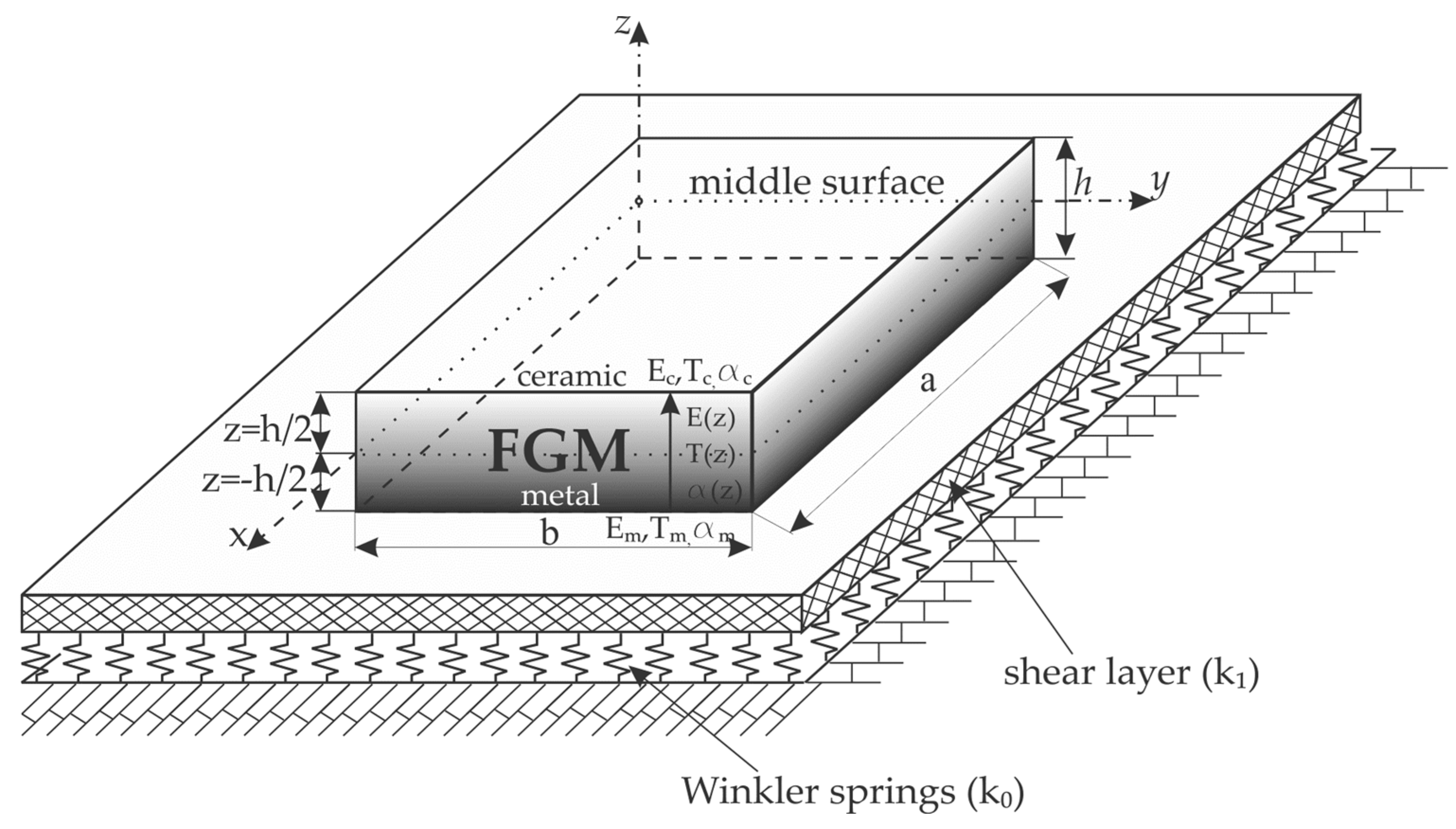
2. Mathematical Model of the Functionally Graded Plate Placed on Elastic Foundation

This paper deals with the FGM rectangular plate (a-length, b-width, and h-height) resting on an elastic foundation, where the z-axis has a direction of thickness h and the x-y plane represents the mid surface of the plate (Figure 3). Mathematical model of elastic foundation is defined by the use of Winkler-Pasternak type of two parameters elastic foundation:
  • k0 is stiffness of Winkler foundation,
  • k1 represents shear stiffness (Pasternak coefficient).
Power law distribution is used to define Young’s modulus of elasticity, thermal expansion coefficient, and temperature change through plate thickness [40]:
E ( z ) = E m + E cm ( 1 2 + z h ) p , E cm = E c E m , α ( z ) = α m + α cm ( 1 2 + z h ) p , α cm = α c α m , T ( z ) = T m + Δ T cr ( 1 2 + z h ) s , Δ T cr = T c T m .
The analytical procedure for determining natural frequencies as well as critical buckling temperature for both linear and nonlinear temperature change across the FG plate thickness is hereby developed.

3. Equilibrium and Stability Equations of FG Plate Placed on Elastic Foundation

By introducing HSDT with shape functions, numerous authors have eliminated the disadvantages of CPT and FSDT.
In order to produce good results for specific dynamical and static problems, many of these shape functions have been introduced. It is important to note that the shape functions proposed by various authors (Table 1) are not generally applicable to all types of problems.
This paper introduces a new shape function:
f ( z ) = z ( cosh ( z h ) 1.388 )
The starting point for developing a new shape function was a comparative analysis of the advantages and disadvantages of existing shape functions given in Table 1. The initial conditions which had to be satisfied in developing a new shape function are: the function has to be an odd function of the thickness coordinate, the function has to satisfy zero stress conditions for out of plane shear stresses, the function has to be analytically integrable in order to additionally increases the precision of the results obtained. Table 1 shows that the newly developed shape function belongs to the category of simple mathematic functions. This makes the process of integration easier and it consequently reduces the calculation time significantly. Since the function is analytically integrable, it is not necessary to switch to numeric integration, and that fact additionally increases the precision of the results obtained.
Here, the assumed form of the displacement field [50] is:
u ( x , y , z , t ) = u 0 ( x , y , t ) z w x ( x , y , t ) + f ( z ) θ x , v ( x , y , z , t ) = v 0 ( x , y , t ) z w y ( x , y , t ) + f ( z ) θ y , w ( x , y , z , t ) = w 0 ( x , y , t ) .
It is necessary to apply the relations between strains and displacements based on von Karman’s non-linear theory of elasticity so as to define the components of unit loads [53]. Considering the effect of the temperature change (1) and thermal expansion that cause a strain α Δ T , as well as using the generalized Hooke’s law, the following unit load components are obtained:
{ N xx N yy N xy } = h / 2 h / 2 { σ xx σ yy τ xy } dz = h / 2 h / 2 [ Q 11 ( z ) Q 12 ( z ) 0 Q 12 ( z ) Q 22 ( z ) 0 0 0 Q 66 ( z ) ] { u 0 x + 1 2 ( w x ) 2 v 0 y + 1 2 ( w y ) 2 u 0 y + v 0 x + w x w y } dz + h / 2 h / 2 [ Q 11 ( z ) Q 12 ( z ) 0 Q 12 ( z ) Q 22 ( z ) 0 0 0 Q 66 ( z ) ] { 2 w 0 x 2 2 w 0 y 2 2 2 w 0 x y } zdz + h / 2 h / 2 [ Q 11 ( z ) Q 12 ( z ) 0 Q 12 ( z ) Q 22 ( z ) 0 0 0 Q 66 ( z ) ] { θ x x θ y y θ x y + θ y x } f ( z ) dz h / 2 h / 2 [ Q 11 ( z ) + Q 12 ( z ) Q 12 ( z ) + Q 22 ( z ) 0 ] α ( z ) T ( z ) dz , { M xx M yy M xy } = h / 2 h / 2 { σ xx σ yy τ xy } zdz = h / 2 h / 2 [ Q 11 ( z ) Q 12 ( z ) 0 Q 12 ( z ) Q 22 ( z ) 0 0 0 Q 66 ( z ) ] { u 0 x + 1 2 ( w x ) 2 v 0 y + 1 2 ( w y ) 2 u 0 y + v 0 x + w x w y } zdz + h / 2 h / 2 [ Q 11 ( z ) Q 12 ( z ) 0 Q 12 ( z ) Q 22 ( z ) 0 0 0 Q 66 ( z ) ] { 2 w 0 x 2 2 w 0 y 2 2 2 w 0 x y } z 2 dz + h / 2 h / 2 [ Q 11 ( z ) Q 12 ( z ) 0 Q 12 ( z ) Q 22 ( z ) 0 0 0 Q 66 ( z ) ] { θ x x θ y y θ x y + θ y x } zf ( z ) dz h / 2 h / 2 [ Q 11 ( z ) + Q 12 ( z ) Q 12 ( z ) + Q 22 ( z ) 0 ] z α ( z ) T ( z ) dz , { P xx P yy P xy } = h / 2 h / 2 { σ xx σ yy τ xy } f ( z ) dz = h / 2 h / 2 [ Q 11 ( z ) Q 12 ( z ) 0 Q 12 ( z ) Q 22 ( z ) 0 0 0 Q 66 ( z ) ] { u 0 x + 1 2 ( w x ) 2 v 0 y + 1 2 ( w y ) 2 u 0 y + v 0 x + w x w y } f ( z ) dz + h / 2 h / 2 [ Q 11 ( z ) Q 12 ( z ) 0 Q 12 ( z ) Q 22 ( z ) 0 0 0 Q 66 ( z ) ] { 2 w 0 x 2 2 w 0 y 2 2 2 w 0 x y } zf ( z ) dz + h / 2 h / 2 [ Q 11 ( z ) Q 12 ( z ) 0 Q 12 ( z ) Q 22 ( z ) 0 0 0 Q 66 ( z ) ] { θ x x θ y y θ x y + θ y x } ( f ( z ) ) 2 dz h / 2 h / 2 [ Q 11 ( z ) + Q 12 ( z ) Q 12 ( z ) + Q 22 ( z ) 0 ] f ( z ) α ( z ) T ( z ) dz , { R y R x } = h / 2 h / 2 { τ xz τ yz } f ( z ) dz = h / 2 h / 2 [ Q 44 ( z ) 0 0 Q 55 ( z ) ] { θ x θ y } ( f ( z ) ) 2 dz ,
where:
{ ε xx ( 0 ) ε yy ( 0 ) γ xy ( 0 ) } = { u 0 x + 1 2 ( w 0 x ) 2 v 0 y + 1 2 ( w 0 y ) 2 u 0 y + v 0 x w 0 x w 0 y } ,   { k xx ( 0 ) k yy ( 0 ) k xy ( 0 ) } = { 2 w 0 x 2 2 w 0 y 2 2 2 w 0 x y } ,   { k xx ( 1 ) k yy ( 1 ) k xy ( 1 ) } = { θ x x θ y y θ x y + θ y x } ,   { k xz ( 2 ) k yz ( 2 ) } = { θ x θ y } ,
and f ( z ) = df ( z ) dz .
The coefficients of the constitutive elasticity tensor could be derived using engineering constants:
Q 11 ( z ) = Q 22 ( z ) = E ( z ) 1 ν 2 ,   Q 44 ( z ) = Q 55 ( z ) = Q 66 ( z ) = E ( z ) 2 ( 1 + ν ) ,   Q 12 ( z ) = ν E ( z ) 1 ν 2 .
Based on the Equation (4), new matrices are defined:
( A ij , B ij ,   D ij ,   E ij ,   F ij ,   G ij ) = h / 2 h / 2 Q ij ( 1 , z , f ( z ) , z 2 , zf ( z ) , ( f ( z ) ) 2 ) dz i , j = ( 1 , 2 , 6 ) , H lr = h / 2 h / 2 Q lr ( f ( z ) ) 2 dz ,   ( l , r ) = ( 4 , 5 ) .
In order to use the principles of minimum potential energy, it is necessary to define strain energy Us, the potential energy of the elastic foundation Ue and the total potential energy Π:
U s = h / 2 h / 2 A ( σ xx [ ε xx α ( z ) T ( z ) ] + σ y [ ε yy α ( z ) T ( z ) ] + σ zz ε zz + τ xy γ xy + τ xz γ xz + τ yz γ yz ) dAdz ,
U e = 1 2 A { k 0 w 2 + k 1 [ ( w x ) 2 + ( w x ) 2 ] } dA ,
П = U s + U e .
By applying the principles of minimum potential energy:
δ П = δ ( U s + U e ) = δ U s + δ U e = A ( N xx δ ε xx ( 0 ) + N yy δ ε yy ( 0 ) + N xy δ γ xy ( 0 ) + M xx δ k xx ( 0 ) + M yy δ k yy ( 0 ) + M xy δ k xy ( 0 ) + P xx δ k xx ( 1 ) + P yy δ k yy ( 1 ) + P xy δ k xy ( 1 ) + R x δ k xz ( 2 ) + R y δ k yz ( 2 ) ) dA + A { k 0 w δ w + k 1 ( w x δ w x + w y δ w y ) } dA = 0 ,
equilibrium equations become:
δ u 0 :   N xx x + N xy y = 0 , δ v 0 :   N yy y + N xy x = 0 ,   δ w 0 : 2 M xx x 2 + 2 2 M xy x y + 2 M yy y 2 + N xx 2 w 0 x 2 + 2 N xy 2 w 0 x y + N yy 2 w 0 y 2 k 0 w 0 + k 1 ( 2 w 0 x 2 + 2 w 0 y 2 ) = 0 , δ θ x :   P xx x + P xy y R x = 0 , δ θ y :   P xy x + P yy y R y = 0 .
Based on the equilibrium Equation (12) and using the displacement components u 0 , v 0 , w 0 , θ x 0 and θ y 0 , the stability equation could be defined. The displacement components of the next stable configuration are:
u = u 0 + u 1 , v = v 0 + v 1 , w = w 0 + w 1 , θ x = θ x 0 + θ x 1 ,   θ y = θ y 0 + θ y 1 ,
where u 1 , v 1 , w 1 , θ x 1 and θ y 1 represent the displacement components of arbitrarily small deviation from the stable configuration. If it is assumed that the temperature is constant in xy-plane of the FG plate and that it changes only in the direction of z-axis, the stability equation can be obtained by substituting the Equation (13) into the Equation (12):
δ u 0 :   N xx 1 x + N xy 1 y = 0 , δ v 0 :   N yy 1 y + N xy 1 x = 0 ,   δ w 0 : 2 M xx 1 x 2 + 2 2 M xy 1 x y + 2 M yy 1 y 2 + N xx 0 2 w 0 x 2 + 2 N xy 0 2 w 0 x y + N yy 0 2 w 0 y 2 k 0 w 1 + k 1 ( 2 w 1 x 2 + 2 w 1 y 2 ) = 0 , δ θ x :   P xx 1 x + P xy 1 y R x 1 = 0 , δ θ y :   P xy 1 x + P yy 1 y R y 1 = 0 .
where N xx 0 , N yy 0 and N xy 0 are the resultants of pre-buckling forces:
N xx 0 = N yy 0 = h / 2 h / 2 E ( z ) α ( z ) T ( z ) 1 υ dz , N xy 0 = 0 .
Analytical solutions are obtained by using assumed solution forms and boundary conditions in accordance with Navier’s methods [54]. Boundary conditions along the edges of the rigidly fixed-simply supported plate rectangular plate are the following:
u 1 = v 1 = w 1 = θ y 1 = N xx 1 = M xx 1 = P xx 1 = 0 along   sides     x = 0   and   x = a , u 1 = v 1 = w 1 = θ x 1 = N yy 1 = M yy 1 = P yy 1 = 0 along   sides     y = 0   and   y = b .
In order to satisfy the previously defined boundary conditions, the following Navier’s solution is assumed [54]:
u 1 ( x , y ) = m = 1 n = 1 U mn 1 cos m π x a sin n π y b , v 1 ( x , y ) = m = 1 n = 1 V mn 1 sin m π x a cos n π y b , w 1 ( x , y ) = m = 1 n = 1 W mn 1 sin m π x a sin n π y b , θ x 1 ( x , y ) = m = 1 n = 1 T xmn 1 cos m π x a sin n π y b , θ y 1 ( x , y ) = m = 1 n = 1 T ymn 1 sin m π x a cos n π y b .
where U mn 1 , V mn 1 , W mn 1 , T xmn 1 , T ymn 1 are parameters which are to be determined.
Based on Navier’s solution, the stability equation becomes:
[ L Ω I ] U = 0 ,
where U = { U mn 1 V mn 1 W mn 1 T xmn 1 T ymn 1 } T and Ω buckling parameter. Coefficients L ij , ( i , j = 1 ÷ 5 ) are defined in the following way:
L 11 = α 2 A 11 + β 2 A 66 ,     L 12 = α β ( A 12 + A 66 ) ,     L 13 = 0 ,     L 14 = α 2 D 11 + β 2 D 66 , L 15 = α β ( D 12 + D 16 ) ,     L 22 = α 2 A 66 + β 2 A 22 ,     L 23 = 0 ,     L 24 = α β ( D 12 + D 16 ) , L 25 = α 2 C 66 + β 2 C 22 ,     L 33 = α 4 E 11 + 2 α 2 β 2 E 12 + 4 α 2 β 2 E 66 + β 4 E 22 , L 34 = α 3 F 11 α β 2 F 12 2 α β 2 E 66 ,     L 35 = α 2 β F 12 2 α 2 β F 66 β 3 F 22 , L 44 = H 44 + α 2 G 11 + α 2 G 66 ,     L 45 = α β ( G 12 + G 66 ) ,     L 55 = H 55 + α 2 G 66 + α 2 G 22 ,
while the matrix I ij ,   ( i , j = 1 ÷ 5 ) is determined as:
I = { 0 , α 2 N x 0 + β 2 N y 0 + k 0 + k 1 ( α 2 + β 2 ) ,     ( i , j = 3 ) ,   α = m π / a ,   β = n π / b  
The determinant in (18) must be equal to zero value in order to get nontrivial solutions:
| L Ω I | = 0 .

4. Equations of Motion of FG Plate Placed on Elastic Foundation

As the subject of this chapter is linear dynamic analysis, the kinematic relations of displacements and deformations are defined under assumptions of small deformations. Since the total potential energy П is represented as the sum of the strain energy of the plate and the potential energy of the elastic foundation (10), for the application of the Hamilton’s principle it is necessary to further define the kinetic energy:
K = 1 2 h / 2 h / 2 A ρ ( z ) [ ( u t ) 2 + ( v t ) 2 + ( w t ) 2 ] dAdz ,
wherein:
  • ρ ( z ) -material density in an arbitrary cross-section z,
As can be seen, as a consequence of the gradient structure of the plate material, the material density represents a function of the z coordinate. The change of density in the direction of z-axis is defined in accordance to the power-law distribution as:
ρ ( z ) = ρ m + ρ cm ( 1 2 + z h ) p ,     ρ cm = ρ c ρ m ,
By substituting the strain energy of the plate (8), the potential energy of the elastic foundation (9) and the kinetic energy (22) into the Hamilton’s principle:
δ t 1 t 1 [ K ( U s + U e ) ] dt = t 1 t 2 [ A ( N xx ε xx ( 0 ) + N yy ε yy ( 0 ) + N xy γ xy ( 0 ) + M xx k xx ( 0 ) + M yy k yy ( 0 ) + M xy k xy ( 0 ) + P xx k xx ( 1 ) + P yy k yy ( 1 ) + P xy k xy ( 1 ) + R x k xz ( 2 ) + R y k yz ( 2 ) ) dA A { k 0 w δ w + k 1 ( w x δ w x + w y δ w y ) } dA + h / 2 h / 2 A ρ ( z ) ( u t δ u t + v t δ v t + w t δ w t ) dAdz ] dt = 0 .
By substituting the strain components expressed by assumed displacement forms as well as by applying the calculus of variations and group the members with the δ u 0 , δ v 0 , δ w 0 , δ θ x and δ θ y , the equations of motion are obtained:
δ u 0 :   N xx x + N xy y = I 1 u ¨ 0 I 2 w ¨ 0 x + I 4 θ ¨ x , δ v 0 :   N yy y + N xy x = I 1 v ¨ 0 I 2 w ¨ 0 y + I 4 θ ¨ y ,   δ w 0 :   2 M xx x 2 + 2 2 M xy x y + 2 M yy y 2 k 0 w 0 + k 1 ( 2 w 0 x 2 + 2 w 0 y 2 ) = I 1 w ¨ 0 + I 2 ( u ¨ 0 x + v ¨ 0 y ) I 3 ( 2 w ¨ 0 x 2 + 2 w ¨ 0 y 2 ) + I 5 ( θ ¨ x x + θ ¨ y y ) , δ θ x :   P xx x + P xy y R x = I 4 u ¨ 0 I 5 w ¨ 0 x + I 6 θ ¨ x , δ θ y :   P xy x + P yy y R y = I 4 v ¨ 0 I 5 w ¨ 0 y + I 6 θ ¨ y .
where I i ( i = 1 , 2 , 3 , 4 , 5 и 6 ) are terms due to inertia defined as:
I 1 = h / 2 h / 2 ρ ( z ) dz , I 2 = h / 2 h / 2 ρ ( z ) zdz , I 3 = h / 2 h / 2 ρ ( z ) f ( z ) dz , I 4 = h / 2 h / 2 ρ ( z ) z 2 dz , I 5 = h / 2 h / 2 ρ ( z ) zf ( z ) dz , I 6 = h / 2 h / 2 ρ ( z ) ( f ( z ) ) 2 dz .
Analytical solutions will be derived for the simply supported rectangular FGM plate, wherein the boundary conditions are defined according to [54] as:
v 0 = w 0 = θ y = N xx = M xx = P xx = R y = 0 ,   on   the   sides   where   x = 0   or   x = a , u 0 = w 0 = θ x = N yy = M yy = P yy = R x = 0 ,   on   the   sides   where   y = 0   or   y = b .
In order to satisfy the previously defined boundary conditions, the following Navier’s solution is assumed:
u 0 ( x , y , t ) = m = 1 n = 1 U mn cos m π x a sin n π y b e i ω t ,   v 0 ( x , y , t ) = m = 1 n = 1 V mn sin m π x a cos n π y b e i ω t , w 0 ( x , y , t ) = m = 1 n = 1 W mn sin m π x a sin n π y b e i ω t , θ x ( x , y , t ) = m = 1 n = 1 T xmn cos m π x a sin n π y b e i ω t ,   θ y ( x , y , t ) = m = 1 n = 1 T ymn sin m π x a cos n π y b e i ω t .
Comparing the assumed form of Navier’s solutions (17) and (28), it can be observed that the only difference between these forms is in the terms e i ω t , where ω is the natural frequency of the system and U mn , V mn , W mn , T xmn , T ymn are parameters to be determined. By substituting (28) into (25) the following equation is obtained:
[ K ω 2 I ] U ¯ = 0 ,
K = [ K 11 K 12 K 13 K 14 K 15 K 22 K 23 K 24 K 25 K 33 K 34 K 35 sym K 44 K 45 K 55 ] , U ¯ = { U mn V mn W mn T xmn T ymn } .
Coefficients K ij , ( i , j = 1 ÷ 5 ) are defined as:
K 11 = α 2 A 11 + β 2 A 66 ,     K 12 = α β ( A 12 + A 66 ) ,     K 13 = 3 B 16 α 2 β B 26 β 3 , K 14 = 2 D 16 α β ,     K 15 = α 2 D 16 + β 2 D 26 ,     K 22 = α 2 A 66 + β 2 A 22 , K 23 = B 16 α 3 3 B 26 α β 2 ,     K 24 = α 2 E 16 + β 2 E 26 ,     K 25 = 2 α β E 26 , K 33 = α 4 E 11 + 2 α 2 β 2 E 12 + 4 α 2 β 2 E 66 + β 4 E 22 ,     K 34 = α 3 F 11 α β 2 F 12 2 α β 2 F 66 , K 35 = α 2 β F 12 2 α 2 β F 66 β 3 F 22 ,     K 44 = H 44 + α 2 G 11 + β 2 G 66 , K 45 = α β ( G 12 + G 66 ) ,     K 55 = H 55 + α 2 G 66 + β 2 G 22 .
while I ij ,   ( i , j = 1 ÷ 5 ) is defined as:
I = [ I 1 0 α I 2 I 4 0 0 I 1 β I 2 0 I 4 α I 2 β I 2 I 3 ( α 2 + β 2 ) + I 1 α I 5 β I 5 I 4 0 α I 5 I 6 0 0 I 4 β I 5 0 I 6 ] ,     α = m π a ,   β = n π b
The determinant in (29) must be equal to zero value in order to get nontrivial solutions:
| K ω 2 I | = 0 .

5. Numerical Examples and Results

In order to verify the derived theoretical results on numerical examples, an original program code for determination of critical buckling temperature as well as for determination natural frequencies of FGM plates has been implemented within software MATLAB. The main goal of this chapter is to check the exactness and the effectiveness of the proposed theory and new shape function. Different numerical examples were done in order to compare obtained results to results based on other shear deformation theory. Analysis were performed for FG plate with metal and ceramic constituents, the mechanical and thermal characteristics of which are given in Table 2.

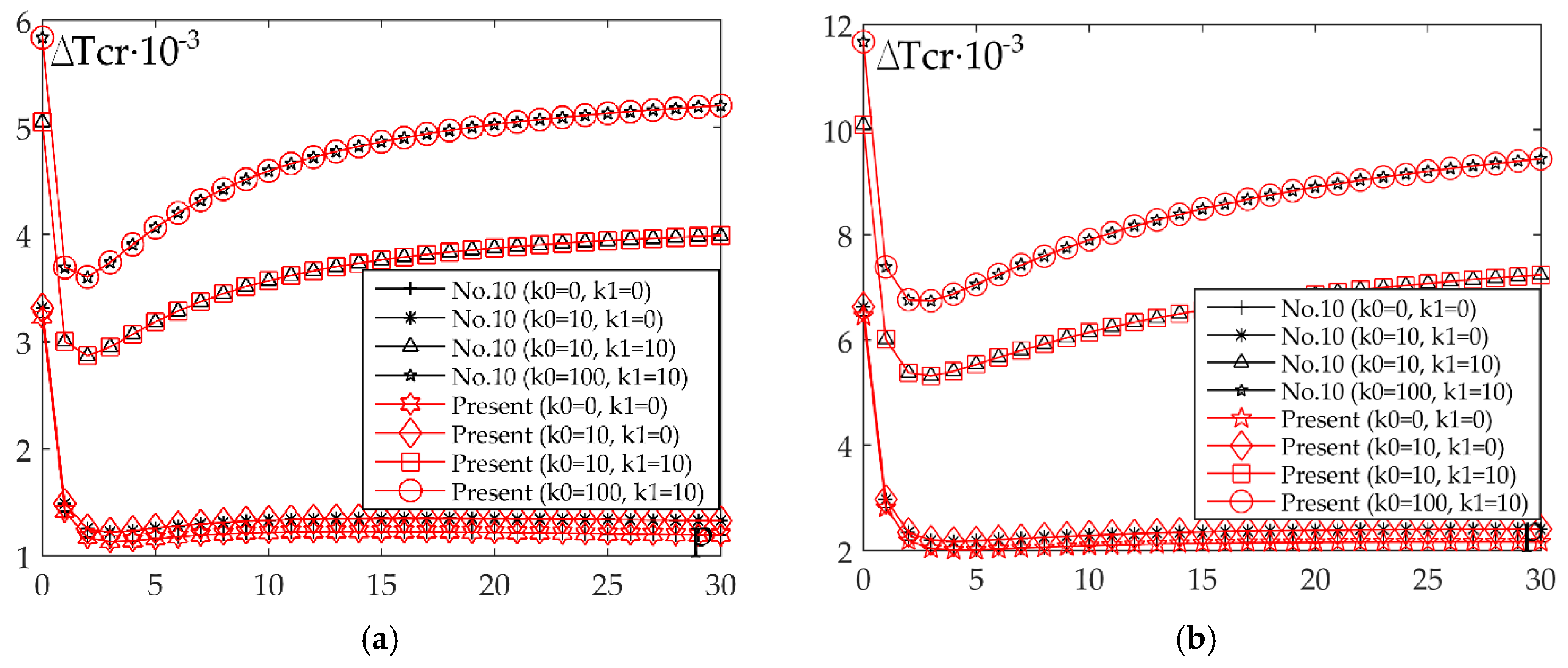
5.1. Thermal Buckling Analysis

This section provides results of the research based on comparative analysis of all shape functions (Table 1) and new proposed function. The obtained results for critical buckling temperatures of FG square and rectangular plates placed on an elastic foundation are totally in accordance with the results by authors in [55] which is applied trigonometric shear deformation plate theory and [25] which is applied HSDT based on the just one shape function.
In Table 3, critical buckling temperatures (∆tcr = ∆Tcr·10−3) of FGM plates placed on an elastic foundation for case a linear temperature change through the plate thickness are presented. Values such as the power law index p, Winkler and Pasternak coefficient k0, k1 and thickness ratios a/h were varied during the analysis of the influence on the critical buckling temperature. By drawing an analogy between these findings where 13 different shape functions were applied, it can be clearly seen that the newly established shape function demonstrates quite similar results. From the findings, we can infer that critical buckling temperatures drops off with the rise of power law index p and ratio a/h. Additionally, Pasternak coefficient k1 has a bigger effect than Winkler coefficient k0 on the critical buckling temperatures.
Table 4 illustrates comparative findings of critical buckling temperatures of FGM plates placed on an elastic foundation for case a nonlinear temperature change through the plate thickness. By drawing an analogy between these findings, the ones where 13 different shape functions were applied, and the ones included in the sources [55], it can be clearly seen that the newly established shape function demonstrates quite similar results.
Figure 4a and Figure 5a clarify the impact of ratio a/b on the critical buckling temperature for case of linear and nonlinear temperature change through the plate thickness. It should be stressed that the rise of a/b ratio leads to the rise of critical temperature, e.g., curves show the harsh rise of a/b ratio functions. Furthermore, the critical buckling temperatures in the same instance are higher for nonlinear than the linear temperature change through the plate thickness.
Figure 4b and Figure 5b illustrate the impact of ratio a/h on the critical buckling temperature for case of linear and nonlinear temperature change through the plate thickness. This diagram exhibits the values of p = 0, 1, 5, 10 and it is evident that the most prominent curve is the one whose value is p = 0, while the remaining curves lie over each other when the value of ratio is a/h > 15.
The impact of the elastic foundation on the critical buckling temperature for case of linear and nonlinear temperature change through the plate thickness is shown in Figure 6a,b. It should be underlined that results are presented for the shape function is No.10 because of its analytical integration. Numerical integration does not have to be employed.
The numerical calculations were done to figure out the influence of every elastic foundation parameter (k0 and k1). This was achieved by varying one of the parameters and setting the other one as a constant. Similarly to previous cases, the analysis is conducted for a linear and nonlinear rise in temperature and the findings are illustrated in Figure 7a and Figure 8a (fixed value k1 and variation of k0) and also in Figure 7b and Figure 8b (fixed value k0 and variation of k1). The Figures provide information about the curves that represent critical buckling temperature changes and their rapid rise that occurs because of the change of coefficient k1, rather than when coefficient k0 changes. Another important observation is that the curve with the most rapid rise has the value p = 10.

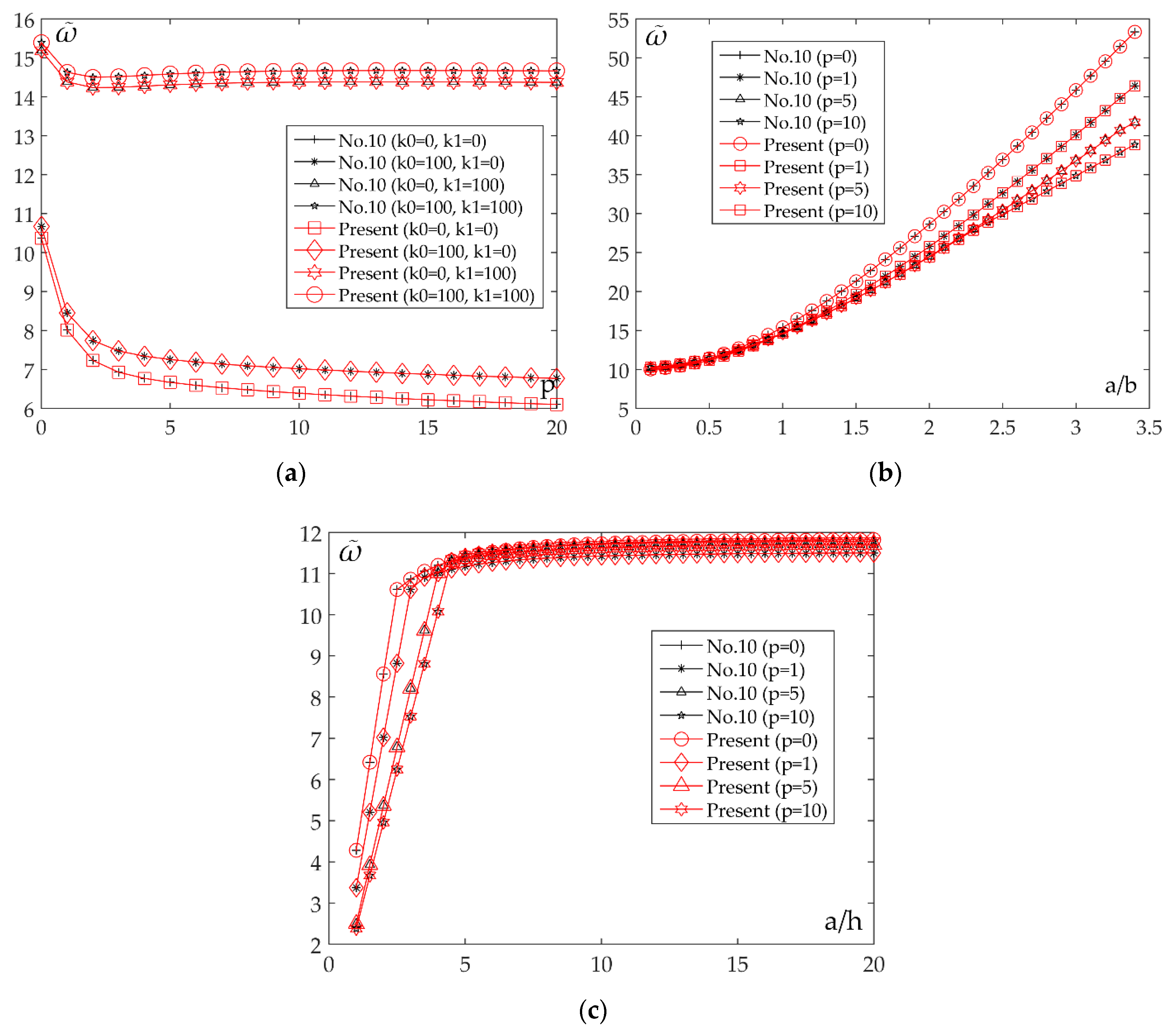
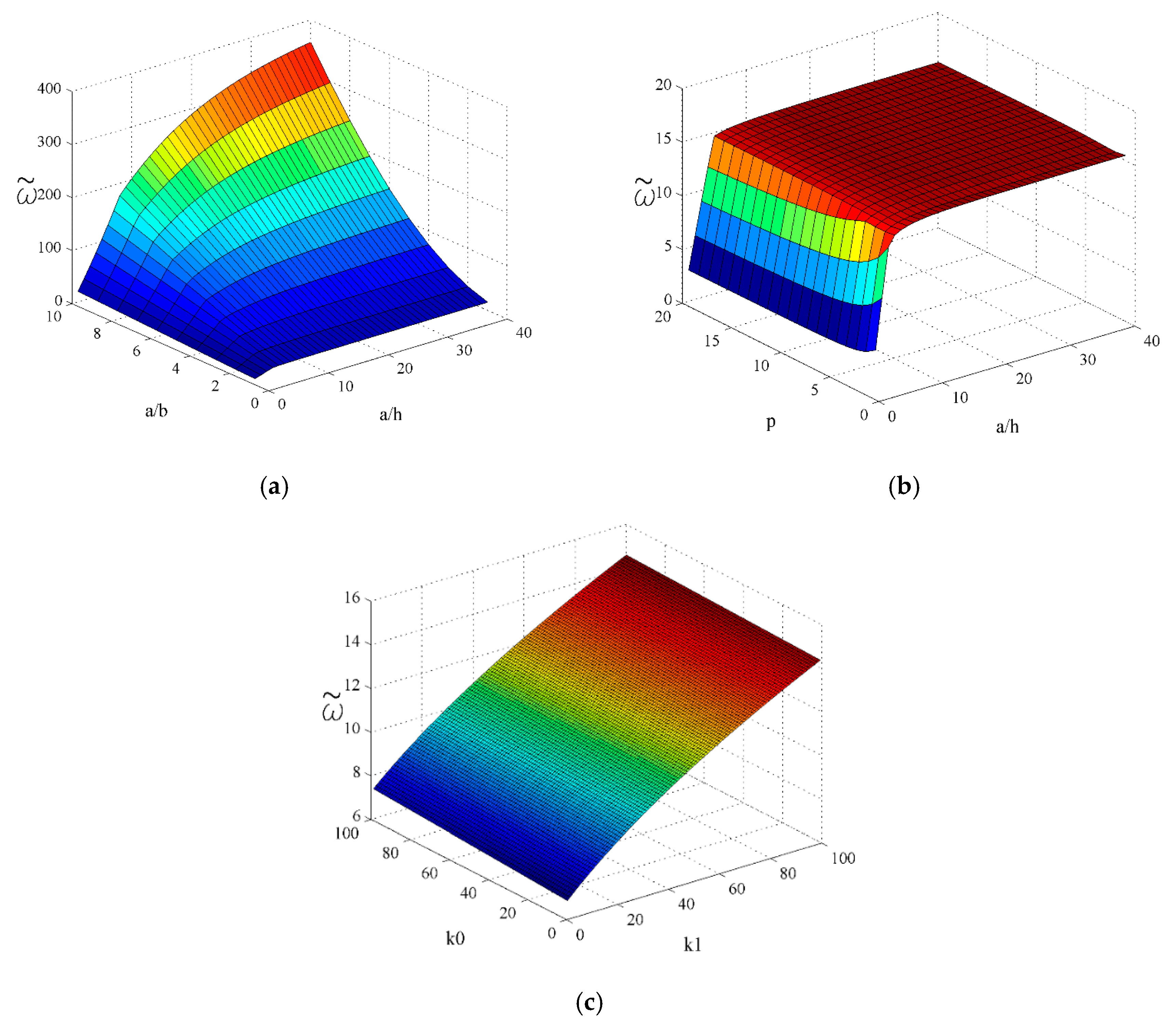
5.2. Free Vibration Analysis

In order to properly evaluate the behaviour of FGM plates, in addition to the results of the static analysis, an analysis of the behaviour of plates in a dynamic environment is also required. This section presents the results of free vibrations of FGM plates placed on an elastic foundation for different values of Winkler coefficient k0, Pasternak coefficient k1, and power law index p. As with the results of the thermal analysis described above, the verification of the developed and implemented theoretical results based on the newly introduced shape function was performed through a tabular representation of the obtained results, in comparison with the results from the literature. The procedure verified in this way was used to obtain other results for plates of different gradient structure. Based on the results of the dynamic analysis, appropriate interpretations and the comments were provided, and certain conclusions made. In order to display the numerical values of natural frequencies, for rectangular and square FGM plates, it is necessary to normalize the obtained values according to:
ω ˜ = ω h ρ m E m .
Table 5 and Table 6 show the non-dimensional natural frequencies ω ˜ of rectangular (a/b = 0.5) and square (a/b = 1) plates resting on an elastic foundation for different values of Winkler coefficient (k0), Pasternak coefficient (k1) and index p. In order to observe the impact of the elastic foundation, the values of k0 = 0 and k1 = 0 were first taken, introducing one coefficient at the time in order to determine which of the two coefficients has a greater impact. By analyzing the results, it is evident that the impact of the coefficient k1 on the ω ˜ is far greater than the impact of the coefficient k0.
Figure 9 shows the diagrams of the non-dimensional natural frequencies ω ˜ of the plates resting on an elastic foundation for different ratios a/h, a/b, and the values of the coefficients k0, k1, and index p. Figure 9a shows the impact of the Winkler coefficient (k0) and Pasternak coefficient (k1) on the values of natural frequencies for the first oscillation mode. It can be clearly observed that the introduction of the coefficient k0 leads to very small changes in the ω ˜ values in comparison to the case of absence of an elastic foundation (k0 = 0 and k1 = 0). On the other hand, when you introduce the coefficient k1, there is an evident change in the value of natural frequencies ω ˜ . The effect of the geometry changes of the plate (a/b ratio) and the index p is shown in the diagram 9b. With the increase of a/b ratio the curves become further away from each other, i.e., the fastest change in the ω ˜ value occurs in a ceramic plate, the slowest change occurs in a metal plate, and in FGM the rate of change depends on the ratio of constituents. Figure 9c shows the effect of different a/h ratios on the values ω ˜ . For smaller values of a/h ratios, the changes in values ω ˜ are greater, while at values of a/h > 5, the effect on the values ω ˜ is decreasing.
Figure 10 shows 3D diagrams of the non-dimensional natural frequencies ω ˜ of the plates resting on an elastic foundation for different ratios a/h, a/b, and values k0, k1, and the index p. This visualization provides a more transparent insight into the previously described effects of certain parameters on the natural frequency values and the conclusions reached. For example, at Figure 10c it can be clearly seen that the impact of the coefficient k1 on the frequency values is far greater than the impact of the coefficient k0.

6. Conclusions

The obtained results presented in the already published articles have been the foundation for developing and introducing the new shape function. The results obtained put an emphasis on the significance and topicality of the research in the field of functionally graded materials. A comprehensive and detailed investigation and systematization of the literature according to the topic have been guided related to the type of problems that authors tried to solve during the analysis of the functionally graded materials. Special focus and attention has been paid to different shear deformation theories that authors have used during the research. The new introduced shape function has been compared to 13 other shape functions that were originally proposed by different authors for the purpose of analysing composite laminates. However, this article implemented the previously mentioned shape 13 shape functions as well as new proposed shape function in order to analyse FGM plates. By comparing obtained results related to the static and dynamic analysis of moderately thick and thick plates, it is possible to conclude that the newly presented shape function can be applied during the analysis of FGM plates. Generally, based on the above research as well as obtained results, the following conclusions could be emphasized:
  • Decreasing the volume fraction of ceramics and increasing the volume fraction of metal in the FGM (the value of p index increases) decreases the value of the critical buckling temperature for both linear and nonlinear cases of temperature distribution through plate thickness
  • Comparative analysis of the results for the linear and nonlinear distribution of the temperature across the plate thickness, and for other fixed parameters of the plate, it can be concluded that higher critical buckling temperatures are obtained for nonlinear distribution
  • The elastic foundation effect shows that critical buckling temperature rapid rise because of the change of Pasternak coefficient k1, rather than when Winkler coefficient k0 changes
  • Based on the analysis of the impact of the Winkler-Pasternak elastic foundation model parameters, similar to the thermal analysis, it was pointed out that the Pasternak coefficient k1 has a far greater influence on natural frequencies than the Winkler coefficient k0

Author Contributions

Conceptualization, G.B. and D.Č.; methodology, A.R. and G.B.; validation, M.B., B.S. and D.D.; formal analysis, A.R., D.Č. and N.M.; writing-original draft preparation, D.Č. and A.R.; writing-review and editing, D.Č. and A.R. All authors have read and agreed to the published version of the manuscript.

Funding

This research received no external funding.

Acknowledgments

Research presented in this paper was supported by Ministry of Education, Science and Technological Development of Republic of Serbia, TR32036, TR33015 and multidisciplinary project III 44007.

Conflicts of Interest

The authors declare no conflict of interest.

References

  1. Jha, D.K.; Kant, T.; Singh, R.K. A critical review of recent research on functionally graded plates. Compos. Struct. 2013, 96, 833–849. [Google Scholar] [CrossRef]
  2. Kohli, G.S.; Singh, T. Review of funtionally graded materials. J. Prod. Eng. 2015, 18, 1–4. [Google Scholar]
  3. Udupa, G.; Shrikantha, S.R.; Gangadharan, K.V. Functionally graded composite materials: An overview. Procedia Mater. Sci. 2014, 5, 1291–1299. [Google Scholar] [CrossRef]
  4. EL-Wazery, M.S.; EL-Desouky, A.R. A review on Functionally Graded Ceramic-Metal Materials. J. Mater. Environ. Sci. 2015, 6, 1369–1376. [Google Scholar]
  5. Thai, H.T.; Kim, S.E. A review of theories for the modeling and analysis of functionally graded plates and shells. Compos. Struct. 2015, 128, 70–86. [Google Scholar] [CrossRef]
  6. Swaminathan, K.; Sangeetha, D.M. Thermal analysis of FGM plates—A critical review of various modeling techniques and solution methods. Compos. Struct. 2017, 160, 43–60. [Google Scholar] [CrossRef]
  7. Xing, Y.; Wang, Z. Closed Form Solutions for Thermal Buckling of Functionally Graded Rectangular Thin Plates. Appl. Sci. 2017, 7, 1256. [Google Scholar] [CrossRef] [Green Version]
  8. Jouneghani, F.Z.; Dimitri, R.; Bacciocchi, M.; Tornabene, F. Free Vibration Analysis of Functionally Graded Porous Doubly-Curved Shells Based on the First-Order Shear Deformation Theory. Appl. Sci. 2017, 4, 1252. [Google Scholar] [CrossRef] [Green Version]
  9. Reddy, J.N. A simple higher-order theory for laminated composite plates. J. Appl. Mech. Trans. ASME 1984, 51, 745–752. [Google Scholar] [CrossRef]
  10. Phan, N.D.; Reddy, J.N. Analysis of laminated composite plates using a higher-order shear deformation theory. Int. J. Numer. Meth. Eng. 1985, 21, 2201–2219. [Google Scholar] [CrossRef]
  11. Reddy, J.N. Analysis of functionally graded plates. Int. J. Numer. Meth. Eng. 2000, 47, 663–684. [Google Scholar] [CrossRef]
  12. Yang, J.; Liew, K.M.; Kitipornchai, S. Dynamic stability of laminated FGM plates based on higher-order shear deformation theory. Comput. Mech. 2004, 33, 305–315. [Google Scholar] [CrossRef]
  13. Akbarzadeh, A.H.; Zad, S.H.; Eslami, M.R.; Sadighi, M. Mechanical behaviour of functionally graded plates under static and dynamic loading. Proc. Inst. Mech. Eng C J. Mech. Eng. Sci. 2011, 225, 326–333. [Google Scholar] [CrossRef]
  14. Zhang, D.G. Nonlinear bending analysis of FGM rectangular plates with various supported boundaries resting on two-parameter elastic foundations. Arch. Appl. Mech. 2014, 84, 1–20. [Google Scholar] [CrossRef]
  15. Kim, Y.W. Temperature dependent vibration analysis of functionally graded rectangular plates. J. Sound Vib. 2005, 284, 531–549. [Google Scholar] [CrossRef]
  16. Alibeigloo, A. Exact solution for thermo-elastic response of functionally graded rectangular plates. Compos. Struct. 2010, 92, 113–121. [Google Scholar] [CrossRef]
  17. Akbarzadeh, A.H.; Abbasi, M.; Eslami, M.R. Coupled thermoelasticity of functionally graded plates based on the third-order shear deformation theory. Thin-Wall Struct. 2012, 53, 141–155. [Google Scholar] [CrossRef]
  18. Bodaghi, M.; Saidi, A.R. Thermoelastic buckling behavior of thick functionally graded rectangular plates. Arch. Appl. Mech. 2011, 18, 1555–1572. [Google Scholar] [CrossRef]
  19. Bouazza, M.; Tounsi, A.; Adda-Bedia, E.A.; Megueni, A. Thermoelastic stability analysis of functionally graded plates: An analytical approach. Comp. Mater. Sci. 2010, 49, 865–870. [Google Scholar] [CrossRef]
  20. Khazaeinejad, P.; Usmani, A.S.; Laghrouche, O. Temperature-dependent nonlinear behaviour of thin rectangular plates exposed to through-depth thermal gradients. Compos. Struct. 2015, 132, 652–664. [Google Scholar] [CrossRef]
  21. Li, Q.; Iu, V.P.; Kou, K.P. Three-dimensional vibration analysis of functionally graded material plates in thermal evironment. J. Sound Vib. 2009, 324, 733–750. [Google Scholar] [CrossRef]
  22. Akavci, S.S.; Tanrikulu, A.H. Static and free vibration analysis of functionally graded plates based on a new quasi-3D and 2D shear deformation theories. Compos. Part B Eng. 2015, 83, 203–215. [Google Scholar] [CrossRef]
  23. Talha, M.; Singh, B.N. Thermo-mechanical induced vibration characteristics of shear deformable functionally graded ceramic–metal plates using finite element method. Proc. Inst. Mech. Eng C J. Mech. Eng. Sci. 2011, 225, 50–60. [Google Scholar] [CrossRef]
  24. Huang, Z.Y.; Lu, C.F.; Chen, W.Q. Benchmark solutions for functionally graded thick plates resting on Winkler Pasternak elastic foundations. Compos. Struct. 2008, 85, 104. [Google Scholar] [CrossRef]
  25. Yaghoobi, H.; Fereidoon, A. Mechanical and thermal buckling analysis of functionally graded plates resting on elastic foundations: An assessment of a simple refined nth-order shear deformation theory. Compos. Part B Eng. 2014, 62, 54–64. [Google Scholar] [CrossRef]
  26. Zhang, D.G.; Zhou, H.M. Mechanical and thermal post-buckling analysis of FGM rectangular plates with variou ssupported boundaries resting on nonlinear elastic foundations. Thin-Wall Struct. 2015, 89, 142–151. [Google Scholar] [CrossRef]
  27. Banić, D.; Bacciocchi, M.; Tornabene, F.; Ferreira, A.J.M. Influence of Winkler-Pasternak Foundation on the Vibrational Behavior of Plates and Shells Reinforced by Agglomerated Carbon Nanotubes. Appl. Sci. 2017, 7, 1228. [Google Scholar] [CrossRef] [Green Version]
  28. Correia, V.M.F.; Madeira, J.F.A.; Araújo, A.L.; Soares, C.M.M. Multiobjective optimization of ceramic-metal functionally graded plates using a higher order model. Compos. Struct. 2018, 183, 146–160. [Google Scholar] [CrossRef]
  29. Correia, V.M.F.; Madeira, J.F.A.; Araújo, A.L.; Soares, C.M.M. Multiobjective optimization of functionally graded material plates with thermo-mechanical loading. Compos. Struct. 2019, 207, 845–857. [Google Scholar] [CrossRef]
  30. Karsh, P.K.; Mukhopadhyay, T.; Dey, S. Stochastic dynamic analysis of twisted functionally graded plates. Compos. Part B Eng. 2018, 147, 259–278. [Google Scholar] [CrossRef]
  31. Karsh, P.K.; Mukhopadhyay, T.; Chakraborty, S.; Naskar, S.; Dey, S. A hybrid stochastic sensitivity analysis for low-frequency vibration and low-velocity impact of functionally graded plates. Compos. Part B Eng. 2019, 176, 107221. [Google Scholar] [CrossRef]
  32. Karsh, P.K.; Mukhopadhyay, T.; Dey, S. Stochastic low-velocity impact on functionally graded plates: Probabilistic and non-probabilistic uncertainty quantification. Compos. Part B Eng. 2019, 159, 461–480. [Google Scholar]
  33. Vaishali; Mukhopadhyay, T.; Karsh, P.K.; Basu, B.; Dey, S. Machine learning based stochastic dynamic analysis of functionally graded shells. Compos. Struct. 2020, 237, 111870. [Google Scholar] [CrossRef]
  34. Li, Y.; Yang, C.; Zhao, H.; Qu, S.; Li, X.; Li, Y. New developments of Ti-based alloys for biomedical applications. Materials 2014, 7, 1709–1800. [Google Scholar] [CrossRef] [PubMed] [Green Version]
  35. Jarrahi, A.; Shirazi, H.A.; Asnafi, A.; Ayatollahi, M.R. Biomechanical analysis of a radial functionally graded dental implant–bone system under multi-directional dynamic loads. J. Braz. Soc. Mech. Sci. Eng. 2018, 40, 249. [Google Scholar] [CrossRef]
  36. Niino, M.; Kisara, K.; Mori, M. Feasibility study of FGM technology in space solar power systems (SPSS). Mater. Sci. Forum. 2005, 492, 163–168. [Google Scholar] [CrossRef]
  37. Jojith, R.; Radhika, N. Fabrication of LM 25/WC functionally graded composite for automotive applications and investigation of its mechanical and wear properties. J. Braz. Soc. Mech. Sci. Eng. 2018, 40, 292. [Google Scholar] [CrossRef]
  38. Lu, L.; Chekroun, M.; Abraham, O.; Maupin, V.; Villain, G. Mechanical properties estimation of functionally graded materials using surface waves recorded with a laser interferometer. NDT E Int. 2011, 44, 169–177. [Google Scholar] [CrossRef] [Green Version]
  39. Wu, C.P.; Liu, Y.C. A review of semi-analytical numerical methods for laminated composite and multilayered functionally graded elastic/piezoelectric plates and shells. Compos. Struct. 2016, 147, 1–15. [Google Scholar] [CrossRef]
  40. Suresh, S.; Mortensen, A. Fundamentals of Functionally Graded Materials; IOM Communications Ltd.: London, UK, 1998. [Google Scholar]
  41. Ambartsumyan, A.S. On the Theory of Anisotropic Shells and Plates. In Proceedings of the Non-Homogeneity in Elasticity and Plasticity: Symposium, Warsaw, Poland, 2–9 September 1958; Olszak, W., Ed.; Pergamon Press: London, UK, 1958. [Google Scholar]
  42. Reissner, E.; Stavsky, Y. Bending and Stretching of Certain Types of Heterogeneous Aeolotropic Elastic Plates. J. Appl. Mech. Trans. ASME 1961, 28, 402–408. [Google Scholar] [CrossRef]
  43. Stein, M. Nonlinear theory for plates and shells including the effects of transverse shearing. AIAA J. 1986, 24, 1537–1544. [Google Scholar] [CrossRef]
  44. Mantari, J.L.; Oktem, A.S.; Soares, C.G. Bending and free vibration analysis of isotropic and multilayered plates and shells by using a new accurate higherorder shear deformation theory. Compos. Part B Eng. 2012, 43, 3348–3360. [Google Scholar] [CrossRef]
  45. Mantari, J.L.; Oktem, A.S.; Soares, C.G. A new trigonometric shear deformation theory for isotropic, laminated composite and sandwich plates. Int. J. Solids Struct. 2012, 49, 43–53. [Google Scholar] [CrossRef] [Green Version]
  46. Karama, M.; Afaq, K.S.; Mistou, S. Mechanical behaviour of laminated composite beam by the new multi-layered laminated composite structures model with transverse shear stress continuity. Int. J. Solids Struct. 2003, 40, 1525–1546. [Google Scholar] [CrossRef]
  47. Aydogdu, M. A new shear deformation theory for laminated composite plates. Compos. Struct. 2009, 89, 94–101. [Google Scholar] [CrossRef]
  48. Mantari, J.L.; Bonilla, E.M.; Soares, C.G. A new tangential-exponential higher order shear deformation theory for advanced composite plates. Compos. B Eng. 2014, 60, 319–328. [Google Scholar] [CrossRef]
  49. Meiche, N.E. A new hyperbolic shear deformation theory for buckling and vibration of functionally graded sandwich plate. Int. J. Mech. Sci. 2011, 53, 237–247. [Google Scholar] [CrossRef]
  50. Soldatos, K. A transverse shear deformation theory for homogeneous monoclinic plates. Acta Mech. 1992, 94, 195–220. [Google Scholar] [CrossRef]
  51. Akavci, S.S. Two new hyperbolic shear displacement models for orthotropic laminated composite plates. Mech. Compos. Mater. 2010, 46, 215–226. [Google Scholar] [CrossRef]
  52. Mechab, B.; Mechab, I.; Benaissa, S. Analysis of thick orthotropic laminated composite plates based on higher order shear deformation theory by the new function under thermo-mechanical loading. Compos. Part B Eng. 2012, 43, 1453–1458. [Google Scholar] [CrossRef]
  53. Praveen, G.N.; Reddy, J.N. Nonlinear transient thermoelastic analysis of functionlly graded ceramic–metal plates. Int. J. Solids Struct. 1998, 35, 4457–4476. [Google Scholar] [CrossRef]
  54. Reddy, J.N. Mechanics of Laminated Composite Plates and Shells: Theory and Analysis; CRC Press LLC: New York, NY, USA, 2004. [Google Scholar]
  55. Zenkour, A.M.; Shoby, M. Thermal buckling of functionally graded plates resting on elastic foundations using the trigonometric theory. J. Therm. Stresses 2011, 34, 1119–1138. [Google Scholar] [CrossRef]
Figure 1. Gradient types.
Applsci 10 04190 g001
Figure 2. Material structure: (a) composite laminate; (b) functionally graded materials (FGM).
Applsci 10 04190 g002
Figure 3. Mathematical model of the functionally graded plate placed on elastic foundation.
Applsci 10 04190 g003
Figure 4. Impact of the ratio a/b and a/h on the critical buckling temperature Δ t cr for case of linear temperature change across plate thickness: (a) a/h = 10, k0 = 10, k1 = 10; (b) a/b = 1, k0 = 10, k1 = 10.
Applsci 10 04190 g004
Figure 5. Impact of the ratio a/b and a/h on the critical buckling temperature Δ t cr for case of nonlinear temperature change across plate thickness: (a) a/h = 10, s = 3, k0 = 10, k1 = 10; (b) a/b = 1, s = 3, k0 = 10, k1 = 10.
Applsci 10 04190 g005
Figure 6. Impact of the power law index p and parameter s on the critical buckling temperature Δ t cr for case of linear and nonlinear temperature change across plate thickness: (a) a/h = 10, a/b = 1, s = 1; (b) a/h = 10, a/b = 1, s = 3.
Applsci 10 04190 g006
Figure 7. Impact of the Winkler coefficient k0 and Pasternak coefficient k1 on the critical buckling temperature Δ t cr for case of linear temperature change across plate thickness: (a) a/h = 10, a/b = 1, k1 = 10; (b) a/h = 10, a/b = 1, k0 = 10.
Applsci 10 04190 g007
Figure 8. Effect of the Winkler coefficient k0 and Pasternak coefficient k1 on the critical buckling temperature Δ t cr for case of nonlinear temperature change across plate thickness: (a) a/h = 10, a/b = 1, s = 3, k1 = 10; (b) a/h = 10, a/b = 1, k0 = 10.
Applsci 10 04190 g008
Figure 9. Impact of the Winkler coefficient k0, Pasternak coefficient k1, power law index p and ratio a/b and a/h on non-dimensional natural frequencies ω ˜ : (a) a/h = 5, a/b = 0.5, m = 1, n = 1; (b) a/h = 5, m = 1, n = 1, k0 = 100, k1 = 100; (c) a/b = 0.5, m = 1, n = 1, k0 = 100, k1 = 100.
Applsci 10 04190 g009
Figure 10. 3D diagrams of the non-dimensional natural frequencies ω ˜ of the plates placed on an elastic foundation for different ratios a/h, a/b, values k0, k1 and index p: (a) p = 5, m = 1, n = 1, k0 = 100, k1 = 100; (b) a/b = 1, m = 1, n = 1, k0 = 100, k1 = 100; (c) a/b = 1, a/h = 5, m = 1, n = 1.
Applsci 10 04190 g010
Table 1. Different type of shape functions.
Number of Function Shape Function, f(z)
No. 1 [41] ( z / 2 ) ( h 2 / 4 z 2 / 3 )
No. 2 [42] ( 5 z / 4 ) ( 1 4 z 2 / 3 h 2 )
No. 3 [43] ( h / π ) sin ( π z / h )
No. 4 [44] sin ( π z / h ) e 1 2 cos ( π h z ) + ( π z / 2 h )
No. 5–6 [45] tan ( mz ) zm sec 2 ( mh / 2 ) , m = { 1 / 5 h , π / 2 h }
No. 7 [46,47] z exp ( 2 ( z / h ) 2 ) , z exp ( 2 ( z / h ) 2 ln α ) ,   α > 0
No. 8 [48] z 2.85 2 ( z / h ) 2 + 0.028 z
No. 9 [49] ξ [ ( h / π ) sin ( π z / h ) z ] , ξ = { 1 , 1 / cosh ( π / 2 ) 1 }
No. 10 [50] h sinh ( z / h ) z cosh ( 1 / 2 )
No. 11 [51] z sec h ( z 2 / h 2 ) z sec h ( π / 4 ) [ 1 ( π / 2 ) tanh ( π / 4 ) ]
No. 12 [51] ( 3 π / 2 ) h tanh ( z / h ) ( 3 π / 2 ) z sec h 2 ( 1 / 2 )
No. 13 [52] z cos ( 1 / 2 ) 1 + cos ( 1 / 2 ) h sin ( z / h ) 1 + cos ( 1 / 2 )
Table 2. Material properties of functionally graded materials (FGM) constituents.
MaterialMaterial Properties
Elasticity Modulus E [ GPa ] Poisson’s Ratio ν Thermal Expansion Coefficient α [ ° C 1 ] Density ρ [ kg / m 3 ]
Aluminum ( Al ) E m = 70 ν = 0.3 α M = 23 10 6 [ ° C 1 ] ρ m = 2702
Alumina ( A l 2 O 3 ) E c = 380 ν = 0.3 α C = 7.4 10 6 [ ° C 1 ] ρ c = 3800
Table 3. Critical buckling temperatures (∆tcr) of FGM plates placed on an elastic foundation for case of linear temperature change across plate thickness (a/b = 1, m = n = 1, and Tm = 5°).
pSource∆tcr
k0 = 0, k1 = 0k0 = 10, k1 = 0k0 = 10, k1 = 10
a/h = 10a/h = 20a/h = 10a/h = 20a/h = 10a/h = 20
0[55]3.22760.8333.31540.8555.04791.2881
[25]3.22730.8333.31510.8555.04761.2881
Present study3.22740.83313.31510.8555.04761.2881
No. 13.22730.8333.31510.8555.04761.2881
No. 23.22730.8333.31510.8555.04761.2881
No. 33.22760.8333.31540.8555.04791.2881
No. 43.23330.83343.32110.85545.05361.2885
No. 53.22730.8333.31510.8555.04761.2881
No. 63.22820.83313.3160.8555.04851.2882
No. 73.22840.83313.31620.8555.04871.2882
No. 83.22850.83313.31630.8555.04881.2882
No. 93.22850.83313.31630.8555.04881.2882
No. 103.22730.8333.31510.8555.04761.2881
No. 113.22880.83313.31660.85515.04911.2882
No. 123.22750.8333.31520.8555.04771.2881
No. 133.22730.8333.31510.8555.04761.2881
1[55]1.4130.35871.48970.37783.0040.7564
[25]1.41290.35871.48960.37783.00390.7564
Present study1.4130.35871.48970.37793.00390.7564
No. 11.41290.35871.48960.37783.00390.7564
No. 21.41290.35871.48960.37783.00390.7564
No. 31.4130.35871.48970.37783.0040.7564
No. 41.41520.35881.49190.3783.00610.7565
No. 51.41290.35871.48960.37783.00390.7564
No. 61.41330.35871.490.37793.00420.7564
No. 71.41330.35871.490.37793.00430.7564
No. 81.41340.35871.49010.37793.00430.7564
No. 91.41340.35871.49010.37793.00430.7564
No. 101.41290.35871.48960.37783.00390.7564
No. 111.41350.35871.49020.37793.00440.7564
No. 121.4130.35871.48970.37783.00390.7564
No. 131.41290.35871.48960.37783.00390.7564
5[55]1.160.29861.25760.3233.18390.8046
[25]1.16060.29871.25820.32313.18450.8046
Present study1.16080.29871.25840.32313.18460.8047
No. 11.16060.29871.25820.32313.18450.8046
No. 21.16060.29871.25820.32313.18450.8046
No. 31.160.29861.25760.3233.18390.8046
No. 41.16040.29861.25790.3233.18420.8046
No. 51.16070.29871.25820.32313.18450.8046
No. 61.16260.29881.26020.32323.18650.8048
No. 71.15970.29861.25730.3233.18350.8045
No. 81.15970.29861.25720.3233.18350.8045
No. 91.15970.29861.25720.3233.18350.8045
No. 101.16070.29871.25830.32313.18460.8046
No. 111.16310.29881.26070.32323.1870.8048
No. 121.16020.29861.25780.3233.1840.8046
No. 131.16060.29871.25820.3233.18440.8046
10[55]1.21830.31561.33170.3443.56990.9035
[25]1.21860.31561.3320.3443.57010.9035
Present study1.21870.31571.33210.3443.57030.9036
No. 11.21860.31561.3320.3443.57010.9035
No. 21.21860.31561.3320.3443.57010.9035
No. 31.21830.31561.33170.3443.56990.9035
No. 41.22060.31581.33390.34413.57210.9037
No. 51.21860.31561.3320.3443.57020.9035
No. 61.22010.31571.33350.34413.57170.9036
No. 71.21840.31561.33180.3443.570.9035
No. 81.21850.31561.33180.3443.570.9035
No. 91.21850.31561.33180.3443.570.9035
No. 101.21860.31561.3320.3443.57020.9035
No. 111.22030.31581.33370.34413.57190.9036
No. 121.21840.31561.33180.3443.56990.9035
No. 131.21860.31561.33190.3443.57010.9035
Table 4. Critical buckling temperatures (∆tcr) of FGM plates placed on an elastic foundation for case of nonlinear temperature change across plate thickness (a/b = 1, m = n = 1, s = 3, and Tm = 5°).
pSource∆tcr
k0 = 0, k1 = 0k0 = 10, k1 = 0k0 = 10, k1 = 10
a/h = 10a/h = 20a/h = 10a/h = 20a/h = 10a/h = 20
0[55]6.45521.66616.63081.7110.09582.5763
Present study6.45471.66616.63031.7110.09532.5763
No. 16.45471.66616.63021.7110.09532.5762
No. 26.45471.66616.63021.7110.09532.5762
No. 36.45521.66616.63081.7110.09582.5763
No. 46.46671.66696.64221.710810.10732.577
No. 56.45471.66616.63021.718210.09532.5762
No. 66.45641.66626.6321.7110.0972.5764
No. 76.45691.66626.63241.710110.09742.5764
No. 86.45711.66636.63261.710110.09772.5764
No. 96.45711.66636.63261.710110.09772.5764
No. 106.45471.66616.63021.710110.09532.5762
No. 116.45771.66636.63321.713910.09832.5764
No. 126.4551.66616.63051.710210.09562.5762
No. 136.45471.66616.63021.7110.09532.5762
1[55]2.82690.71762.98040.7566.00971.5133
Present study2.82680.71762.98020.7566.00961.5133
No. 12.82670.71762.98020.75596.00951.5133
No. 22.82670.71762.98020.75596.00951.5133
No. 32.82690.71762.98040.7566.00971.5133
No. 42.83120.71792.98470.75626.0141.5136
No. 52.82670.71762.98020.75596.00951.5133
No. 62.82740.71762.98080.7566.01021.5133
No. 72.82750.71762.9810.7566.01031.5133
No. 82.82760.71762.98110.7566.01041.5133
No. 92.82760.71762.98110.7566.01041.5133
No. 102.82670.71762.98020.75596.00951.5133
No. 112.82780.71772.98130.7566.01061.5134
No. 122.82680.71762.98030.7566.00961.5133
No. 132.82670.71762.98020.75596.00951.5133
5[55]2.01520.51882.18470.56125.53091.3977
Present study2.01650.51892.1860.56135.53221.3978
No. 12.01620.51882.18580.56125.53191.3978
No. 22.01620.51882.18580.56125.53191.3978
No. 32.01520.51882.18470.56115.53091.3977
No. 42.01570.51882.18530.56125.53151.3977
No. 52.01630.51882.18580.56125.5321.3978
No. 62.01970.51912.18920.56155.53541.398
No. 72.01460.51872.18410.56115.53031.3977
No. 82.01450.51872.18410.56115.53021.3977
No. 92.01450.51872.18410.56115.53021.3977
No. 102.01640.51892.18590.56125.53211.3978
No. 112.02060.51912.19010.56155.53631.3981
No. 122.01540.51882.18490.56125.53111.3977
No. 132.01610.51882.18560.56125.53181.3978
10[55]2.09710.54332.29230.59216.14481.5552
Present study2.09780.54342.29290.59226.14551.5553
No. 12.09760.54332.29280.59216.14531.5553
No. 22.09760.54332.29280.59216.14531.5553
No. 32.09710.54332.29230.59216.14481.5552
No. 42.1010.54362.29610.59246.14871.5555
No. 52.09760.54332.29280.59216.14531.5553
No. 62.10020.54352.29540.59236.14791.5554
No. 72.09730.54332.29250.59216.1451.5552
No. 82.09730.54332.29250.59216.1451.5552
No. 92.09730.54332.29250.59216.1451.5552
No. 102.09770.54332.29280.59216.14541.5553
No. 112.10050.54352.29570.59236.14821.5555
No. 122.09720.54332.29240.59216.14491.5552
No. 132.09750.54332.29270.59216.14521.5553
Table 5. Non-dimensional natural frequencies ( ω ˜ ) of rectangular FGM plates placed on an elastic foundation for different values of the Winkler coefficient k0, Pasternak coefficient k1, and power law index p (a/b = 0.5, a/h = 5, m = 1, n = 1).
a/bk0k1Theory ω ˜
a/h = 5
p = 0p = 1p = 5p = 10
0.500Present study6.7615.20164.37614.206
No. 16.76095.20154.37574.2058
No. 26.76095.20154.37574.2058
No. 36.76165.2024.37334.205
No. 46.7755.21084.37534.2136
No. 56.76095.20154.37574.2058
No. 66.76285.20274.38324.211
No. 76.76365.20334.37224.2055
No. 86.76385.20344.37214.2056
No. 96.76385.20344.37214.2056
No. 106.76095.20154.37594.2059
No. 116.76425.20364.38524.2117
No. 126.80315.22914.44344.2771
No. 136.76095.20154.37544.2056
1000Present study7.21255.86545.23585.1214
No. 17.21255.86535.23545.1211
No. 27.21255.86535.23545.1211
No. 37.21325.86575.23365.1205
No. 47.22565.87345.23535.1274
No. 57.21255.86535.23555.1212
No. 67.21425.86645.24155.1252
No. 77.2155.86685.23275.1209
No. 87.21525.8675.23265.121
No. 97.21525.8675.23265.121
No. 107.21255.86535.23575.1212
No. 117.21555.86725.24315.1258
No. 127.25175.88935.29025.1777
No. 137.21255.86535.23525.121
0100Present study11.11510.84510.99211.079
No. 111.11510.84510.991911.0793
No. 211.11510.84510.991911.0793
No. 311.115410.845210.991411.0791
No. 411.122610.848410.992211.0814
No. 511.11510.84510.991911.0793
No. 611.11610.845510.993611.0803
No. 711.116410.845710.991211.0793
No. 811.116610.845710.991211.0794
No. 911.116610.845710.991211.0794
No. 1011.11510.84510.99211.0793
No. 1111.116810.845810.99411.0804
No. 1211.13810.855211.007711.0949
No. 1311.11510.84510.991811.0792
100100Present study11.39511.17811.359311.4558
No. 111.395211.17811.359311.4558
No. 211.395211.17811.359311.4558
No. 311.395611.178211.358811.4557
No. 411.402611.181211.359611.4578
No. 511.395211.17811.359311.4558
No. 611.396211.178411.360811.4567
No. 711.396611.178611.358711.4559
No. 811.396711.178711.358711.4559
No. 911.396711.178711.358711.4559
No. 1011.395211.17811.359311.4558
No. 1111.396911.178711.361211.4568
No. 1211.417411.187611.373711.47
No. 1311.395211.17811.359211.4557
Table 6. Non-dimensional natural frequencies ( ω ˜ ) of square FGM plates placed on an elastic foundation for different values of the Winkler coefficient k0, Pasternak coefficient k1, and power law index p (a/b = 1, a/h = 5, m = 1, n = 1).
a/bk0k1Theory ω ˜
a/h = 5
p = 0p = 1p = 5p = 0
100Present study10.37618.01216.66876.3883
No. 110.37618.01216.66776.3879
No. 210.37618.01216.66776.3879
No. 310.37798.01336.6636.3864
No. 410.40868.03366.66846.4062
No. 510.37618.01216.66796.3879
No. 610.388.01476.68386.3987
No. 710.38248.01636.66076.3877
No. 810.38318.01676.66066.388
No. 910.38318.01676.66066.388
No. 1010.37618.01216.66836.3881
No. 1110.3838.01666.68816.4001
No. 1210.46988.07396.81556.5423
No. 1310.37628.01226.66726.3876
1000Present study10.67228.45177.25427.0179
No. 110.67238.45177.25347.0175
No. 210.67238.45177.25347.0175
No. 310.6748.45287.24917.0162
No. 410.70378.47187.25417.0339
No. 510.67228.45177.25357.0176
No. 610.6768.45417.26787.0271
No. 710.67838.45567.24717.0174
No. 810.6798.4567.2477.0177
No. 910.6798.4567.2477.0177
No. 1010.67228.45177.25397.0177
No. 1110.67898.45597.27177.0284
No. 1210.76298.50967.38657.1553
No. 1310.67238.45177.25297.0173
0100Present study15.186714.381814.305414.376
No. 115.186714.381814.305214.3759
No. 215.186714.381814.305214.3759
No. 315.187814.382314.30414.3757
No. 415.206614.39114.306414.3818
No. 515.186714.381814.305214.376
No. 615.189114.382914.309414.3785
No. 715.190614.383614.303614.3763
No. 815.19114.383814.303614.3764
No. 915.19114.383814.303614.3764
No. 1015.186714.381814.305314.376
No. 1115.19114.383814.310514.3788
No. 1215.244414.408614.346314.4167
No. 1315.186814.381814.30514.3759
100100Present study15.390414.630414.584614.6636
No. 115.390414.630514.584314.6636
No. 215.390414.630514.584314.6636
No. 315.391414.630914.583314.6634
No. 415.409914.639414.585614.6692
No. 515.390414.630514.584414.6636
No. 615.392714.631514.588314.666
No. 715.394114.632214.582914.6639
No. 815.394514.632314.582914.664
No. 915.394514.632314.582914.664
No. 1015.390414.630514.584514.6636
No. 1115.394514.632414.589414.6663
No. 1215.44714.656414.623314.7021
No. 1315.390414.630514.584214.6635

