Review

New Developments and Progress in Absorption Chillers for Solar Cooling Applications

CREVER–Group of Applied Thermal Engineering, Department of Mechanical Engineering, Universitat Rovira i Virgili, Av. Països Catalans 26, 43007 Tarragona, Spain
*
Author to whom correspondence should be addressed.
Appl. Sci. 2020, 10(12), 4073; https://doi.org/10.3390/app10124073
Submission received: 4 May 2020 / Revised: 3 June 2020 / Accepted: 8 June 2020 / Published: 12 June 2020
(This article belongs to the Special Issue Solar Cooling Systems)

Abstract

:
At present, novel, small-to-large capacity absorption chillers with unique technical features have emerged on the global market, and laboratory and pre-industrial prototypes have also been developed. These chillers have been designed for the efficient use of low-grade heat sources; some are air-cooled, small capacity systems; compact water/LiBr chillers; or solar-gas-fired single/double-effect chillers. Also, some advanced commercial absorption chillers have an extensive temperature glide in the driving heat stream (>30 K) which extracts approximately twice as much heat (~200%) as the single-effect chiller. This large temperature glide means that the chillers are well suited to solar thermal collector installations and district heating networks, and the extra driving heat increases cold production. Moreover, recent advances in R718 turbo compressor technologies have helped to solve the problems water/LiBr absorption chillers have in adapting to extreme operating conditions (e.g., high ambient temperature, >35 °C) by using a compressor-boosted absorption chiller configuration. This review paper presents and discusses the developments and progress in these absorption chiller technologies. In summary, the new absorption chillers may be useful for developing efficient, cost-effective, and robust solar cooling solutions that are needed to mitigate the unsustainable impact of the rising global demand for space cooling.

1. Introduction

According to an International Energy Agency (IEA) [1] report, the global energy required for space cooling applications will increase three-fold over the next 30 years (i.e., it will rise to 6200 TWh by 2050) if the current policies and targets are continued. This projected energy demand is mainly due to the fact of economic growth and population increases in the hotter regions of the world, 50% of which is contributed to by three countries (i.e., China, India, and Indonesia). Also, more people are interested in comfort cooling due to the fact of rising living standards and increases in the income of the burgeoning middle classes in these countries. Thus, the total number of air conditioners in buildings will increase by approximately 250% between 2016 and 2050, from 1.6 billion to 5.6 billion units [1,2]. In addition, the global electrical power capacity needed to meet these space cooling demands will also increase from 850 GW in 2016 to 3350 GW in 2050 [1]. In 2018, the use of air conditioners and electric fans to satisfy cooling demand accounted for nearly 20% of the total electricity consumed in buildings (equivalent to 10% of the world’s electricity consumption) [2]. Moreover, air conditioning will account for approximately 37% of the world’s growth in electricity demand by 2050 [3].
The global air conditioning market is dominated by technologies based on vapor-compression refrigeration cycles driven by electricity and uses synthetic refrigerants (with considerable global warming potential). The current air conditioning systems comprise packaged air conditioners, split-system air conditioners, and various types of compression chillers (e.g., centrifugal, reciprocating, or screw-type compression chillers). Packaged air conditioners include window units, terminal air conditioners, portable units, and rooftop units. In addition, split-system air conditioners range from small single room units to large systems that can supply cold to large buildings.
Solar thermal energy-driven systems for space cooling and refrigeration applications are attractive solutions for three main reasons [1,3,4]: (1) they use natural refrigerants (such as ammonia and water) which have recently been pushed by national and international regulations (e.g., European F-gas regulation No. 517/2014); (2) they consume less electricity and reduce peak electricity demand, which is especially beneficial in countries with significant cooling needs and electric grid constraints; and (3) the concurrence of solar radiation and the cooling demands of most buildings can save costly electricity in peak periods. Hence, they help to reduce the consumption of fossil fuels and their associated greenhouse gas (GHG) emissions. They can also be an option for storing solar heat for cooling in the evenings, nights, and mornings [3].
Globally, an estimated 1800 solar cooling systems have been installed by 2018, of which 70% were small- and medium-capacity (<350 kW (100 TR)) systems in Europe [3]. Most of these systems use relatively mature technologies: non-tracking solar thermal collectors and absorption chillers. Large-scale systems (>350 kW cooling capacity) that use absorption chillers continue to improve their performance and decrease capital investment costs. This is due to the significant increase in the performance of flat-plate solar collectors (up to 120 °C) and economies of scale for the cost competitiveness of solar cooling applications (e.g., for large office buildings, hotels, and hospitals). The world’s largest solar cooling system with a nominal capacity of 1750 kW was installed and commissioned in Arizona (USA) in 2014. This system uses a single-effect water/LiBr chiller driven by a 4865 m2 roof-mounted solar collector field with a thermal capacity of 3400 kW [3]. However, only three large solar absorption cooling systems were deployed in 2018, of which two were driven by evacuated tube collectors and installed in Italy. Another system using Fresnel collectors was installed in Jordan. The other recent large-scale installations were in 2017 in India (528 kW cooling capacity using 1575 m2 evacuated tube collectors), Nicaragua (1023 kW cooling capacity using 4450 m2 flat plate collectors), and Singapore (880 kW cooling capacity using 2472 m2 flat plate collectors) [3].
Only a few solar thermal cooling systems have been installed worldwide, although there have been significant technical and economic improvements in solar collector technologies. The main obstacles to the more extensive deployment of these systems are their lack of economic competitiveness, low energy efficiency, large footprint, and operational limitations. This is mostly due to the high capital investment required, the need for compactness, and the limited working range of absorption chillers compared to the grid electricity-driven compression chiller, as well as high parasitic energy consumption and an inefficient backup system. Therefore, absorption chillers with unique technical features can be adopted to address these technical and economic obstacles and implement cost-effective and reliable solar thermal space cooling systems.
Solar absorption cooling systems based on classical absorption chiller technologies have been reviewed elsewhere [5,6,7,8,9,10] and related aspects have also been discussed [11]. These review papers focused on theoretical studies [5,6] and experimental investigations [8] into solar heat-driven cooling systems (including absorption, adsorption, and ejector cooling systems). Moreover, Infante Ferreira and Kim [7] reviewed and discussed the technical and economic performances of various types of solar cooling technologies (including absorption chiller-based systems) using location specific data (for central Spain and the Netherlands). Besides, the type of solar collector technologies used in these cooling systems, their integration, and the system’s operation performance have been described and discussed in, for example, Shirazi et al. [10]. However, these reviews have overlooked the current status of commercially available absorption chiller technologies, and developments in laboratory and pre-industrial absorption chiller prototypes focused on solar cooling applications. Thus, there is a gap in the literature on these aspects and new advances in absorption chiller technologies. Accordingly, the present article presents and discusses recent developments in absorption chiller technologies that are useful for the efficient and cost-effective use of solar resources for space cooling applications. These newly developed absorption chillers have key unique features compared to traditional market-available absorption chillers, namely, a small-capacity air-cooled unit; a compact water/LiBr chiller; a high-efficiency compact reversible absorption chiller for cooling and heating applications; a large temperature glide of the driving heat; efficient use of backup fossil fuel resources, and others.
This article is structured as follows. Section 2 describes the layout of a typical solar absorption cooling system and its components as well as the challenges of classical absorption chillers. Section 3 discusses recently developed commercial absorption chillers with the new features. Section 4 discusses advances made in laboratory and pre-industrial absorption chiller prototypes using ammonia-based working fluids and a water/LiBr mixture with a new set of features. Section 5 considers research trends and opportunities to further improve the capacity of these absorption chiller technologies to exploit solar energy. The paper concludes with a summary of the key findings in Section 6.

2. Solar-Powered Absorption Cooling Systems

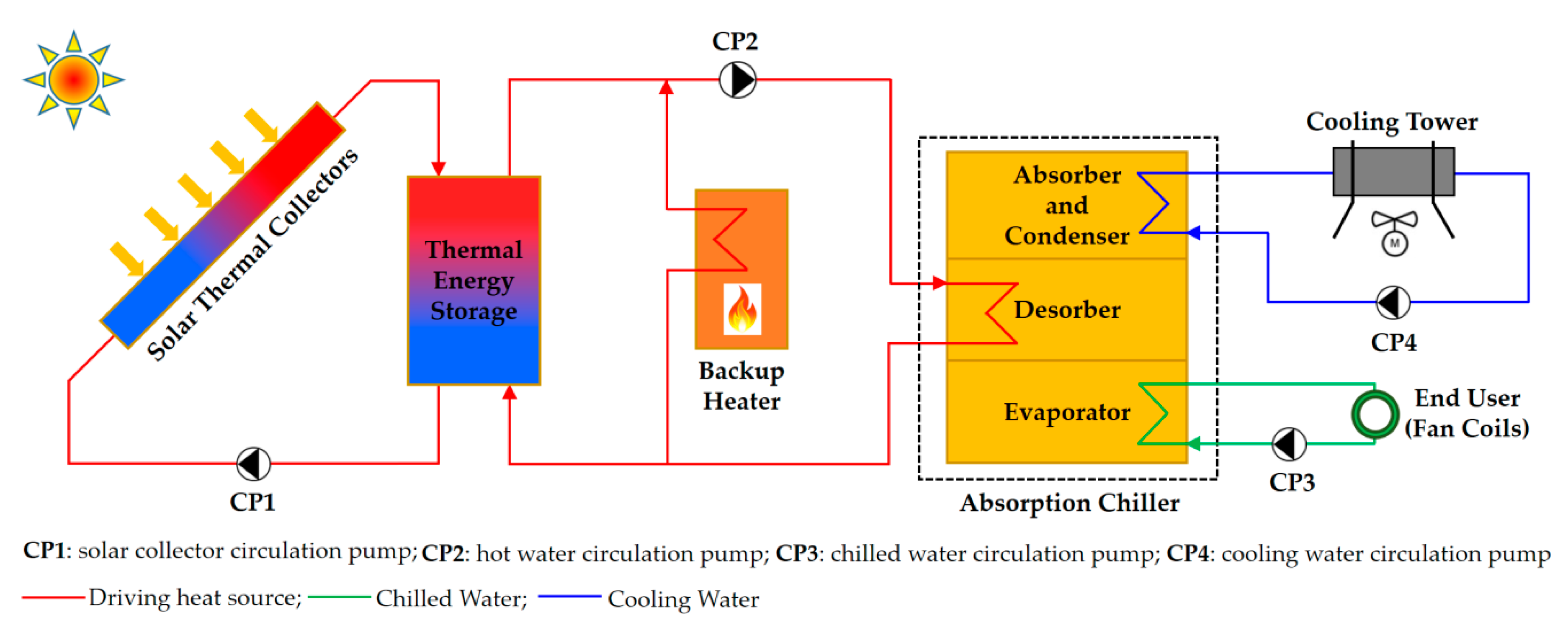
2.1. System Description

Natural gas or industrial waste heat-driven absorption chillers are usually deployed in large buildings for space cooling applications [10]. However, in recent years, the potential of absorption chillers to use solar energy has been shown in several demonstration projects around the world. A typical solar-driven absorption cooling system (see Figure 1) has four main components: namely, a solar thermal collector, an absorption chiller, a backup heater, and a thermal energy storage unit (e.g., hot water storage tank).
The solar thermal collector converts incident solar radiation to heat, which is transferred to the thermal energy storage medium via a heat transfer fluid (usually water or thermal oil) circulated using a circulation pump (i.e., CP1 in Figure 1). The collected heat then drives the absorption chiller to provide the required cooling effect, which is carried by the chilled water loop to the cold distribution unit available at the end-user (e.g., fan coils). The heat rejected from the absorption chiller (i.e., the sum of the driving heat and end-user thermal load) is typically dissipated through a cooling water loop to the atmosphere by using a cooling tower. Because of the intermittent nature of solar energy, the system is equipped with a backup heater and thermal energy storage unit (Figure 1). These units are needed to operate the solar cooling system smoothly by providing residence time in the chiller when solar radiation varies (e.g., due to the cloud cover). They are particularly crucial for absorption chillers which have slow startup times and a dilution cycle when going into shutdown [12]. For the system’s specific components and operation strategies, there are many options that impact the system’s performance and operation boundary.

2.2. Conventional Absorption Chillers—Technical Challenges

Solar absorption cooling systems are often based on classical/conventional absorption chillers available on the market. However, most current absorption chillers have problems in effectively exploiting solar resources in an energy-efficient (from a primary energy viewpoint) and cost-effective way. Hence, the main hurdle for the broader deployment of such systems is that most commercially available absorption chillers lack key technical features. The limitations of these technical features are the following.
  • Heat rejection. High ambient temperature has two adverse effects: (1) an increased cooling load of the building and (2) a lower potential for heat rejection of the cooling tower. An air-cooled heat rejection system involves increasing the absorber and condenser temperatures which creates the need for high-temperature driving heat in the absorption chillers. In water/LiBr absorption chillers, crystallization is the main obstacle to operating the chiller at high ambient temperature, so various methods have been proposed and applied to limit the risk. These methods include the use of chemical inhibitors, heat and mass transfer enhancement in the absorber, and boosting the absorber pressure using mechanical compression. Consequently, the absorption chillers’ potential to reject heat to the atmosphere is hampered, particularly in hot climates. Thereby, evaporative or wet cooling towers are commonly required which is a shortcoming in regions with a scarcity of water. Even in regions where water is not a limited resource, the costs of water and bacteria treatment in evaporative cooling towers of small capacity systems can be as high as 30–40% of the operating costs. Therefore, the absorption systems currently available are relatively expensive in terms of capital expenditure (CAPEX) and operating expenses (OPEX).
  • Compactness. The cost of the heat exchangers is the biggest contribution to the capital investment of any chiller technology. In this regard, absorption chillers always have a downside compared to compression chiller technologies, since they have more heat and mass exchanger components. So, among other factors, such as reducing the consumption of parasitic electricity, if absorption chillers are to be economically competitive, heat exchangers need to be smaller. Conventional absorption chillers are unnecessarily large because of dead spaces that do not have any function (i.e., which are not involved in the cooling process [13,14,15]). Moreover, since absorption chillers are large, it is usually impossible or very difficult to retrofit them in existing buildings. Therefore, there is a significant economic incentive to minimize the overall size of the chiller in any new developments.
  • Capacity. The capacity of most commercial absorption chillers is 300 kW or more. In terms of capacity, shell and tube heat exchangers are state-of-the-art technologies; in these chillers, copper tubes are rolled into the heavy front plates to ensure vacuum operating conditions inside the water/LiBr absorption chiller. Using this practice in small-scale chillers (<200 kW) leads to a high specific cost [13]. On the other hand, small chiller machines based on coiled tube heat exchangers are available from some manufacturers, but they have high-pressure drops which lead to high parasitic electricity demands (i.e., they limit the advantages of heat-driven chillers) [13].
  • Temperature glide of the driving heat. A conventional single-effect water/LiBr absorption chiller typically uses 85–90 °C hot water as its driving heat and releases it at about 75–80 °C (i.e., a temperature glide of up to 10 K) [16]. For example, in several chillers driven by district heat, the driving heat transfer medium only cools by around 10 °C. This means that a large proportion of the useable heat at a relatively high temperature is recirculated unnecessarily to the driving heat source (e.g., district heat network or solar thermal collector installation). It also requires high pump capacity and electricity consumption.

2.3. Primary Energy Use

Another main issue for the supply of cost-competitive cold using absorption chillers is the effective use of the primary energy of the entire solar absorption cooling system (Figure 1) [17]. Hence, apart from increasing thermal efficiency (i.e., high thermal COP, Equation (1)), energy density (cooling capacity per chiller volume), and reducing capital investment, the consumption of parasitic electricity is a crucial factor in solar space cooling systems based on absorption chillers. The thermal COP, C O P t h , is defined as the ratio of the cooling capacity, Q ˙ c o l d , to the driving heat input ( Q ˙ d h s ):
C O P t h = Q ˙ c o l d Q ˙ d h s
The parasitic electricity consumption is the electricity consumed by the circulation pumps to drive heat, reject heat, and carry cold, and other systems such as fans and the control system. The electrical efficiency of the system is determined in terms of electrical COP, C O P e l , defined as the ratio of the cooling capacity to the total parasitic electricity consumption ( W ˙ t o t a l , e l ):
C O P e l = Q ˙ c o l d W ˙ t o t a l , e l
Furthermore, the contribution of solar energy ( Q ˙ s o l ) to cold production is often expressed in terms of solar fraction (SF) as:
S F = Q ˙ s o l Q ˙ d h s
In solar-assisted absorption cooling systems, the driving heat is the sum of solar heat and auxiliary heat from the backup system (e.g., gas-fired heater (or boiler)): Q ˙ d h s = Q ˙ s o l + Q ˙ b .
The primary energy, P E a b s , demand of the solar absorption cooling system includes: (i) the part associated with the parasitic electricity demand (i.e., W ˙ t o t a l , e l / η e l ) and (ii) the demand of the backup heater ( Q ˙ d h s ( 1 S F ) / η b ). η e l and η b are the electric power plant and backup heater efficiencies, respectively. Then, the primary energy rate ( P E R a b s ) of the system becomes [18]:
P E R a b s = Q ˙ c o l d P E a b s = Q ˙ c o l d ( Q ˙ d h s ( 1 S F ) / η b ) + ( W ˙ t o t a l , e l / η e l )
The solar-assisted absorption cooling system is more competitive than the conventional cooling system when its primary energy rate, P E R a b s , is higher than the electricity-driven vapor compression chiller ( P E R c o m ) which is the benchmark for space cooling technology. This means that the primary energy rate ratio ( π ), defined in Equation (5), must be higher than one [18].
π = η b · C O P t h , a b s η e l · C O P c o m ( 1 + p a · ( 1 + C O P c o m ) 1 + p a · ( 1 + C O P t h , a b s ) · ( η b / η e l ) S F )
where C O P t h , a b s is the absorption chiller thermal COP, C O P c o m the compression chiller COP, and p a the parasitic electrical power demand ratio. The value of p a is equivalent to the ratio of the parasitic electrical power demand to the heat rejected by the absorption chiller, i.e., approximately W ˙ t o t a l , e l / ( Q ˙ d h s + Q ˙ c o l d ) [17].

3. Newly Developed Commercial Absorption Chillers

This section discusses the recently developed commercial water/LiBr absorption chillers with unique features for effectively using solar energy for small- to large-scale space cooling applications. These features include heat rejection without cooling towers (i.e., directly and indirectly air-cooled), high efficiency, compactness, use of dual heat sources with effective backup fuel, and a large temperature glide in the driving heat source.

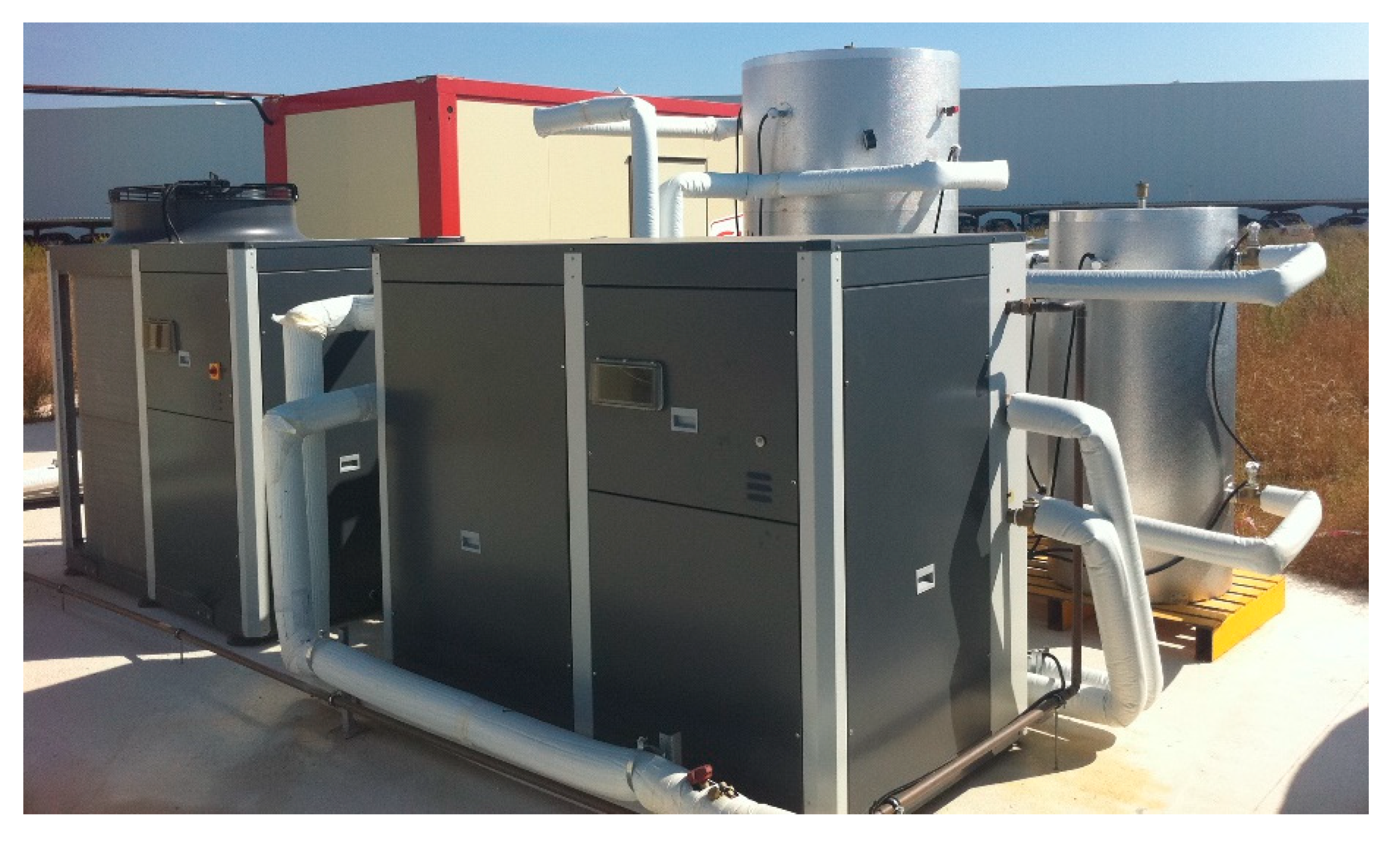
3.1. Air-Cooled Small Capacity Chiller

The solar absorption cooling system benefits if dry cooling towers are used because less maintenance is required and operational costs are lower, especially in a small capacity range.
An air-cooled small capacity water/LiBr chiller (ASC) was developed for small-scale applications [19,20] which introduced a new concept in solar space cooling. It consisted of three main components—flat plate solar thermal collectors, an ASC, and several types of indoor cooling devices—and made it possible to replace the most typical space cooling systems used in residential and small commercial buildings (i.e., split air conditioner systems which were often designed with mounted indoor cooling devices and outdoor electricity-driven vapor compression chillers). The solar space cooling that uses ASC (depicted in Figure 2) is a stand-alone system based on a modular design that replaces electricity-driven split air conditioner systems, of which there were about 145 million units worldwide in 2018.
Additionally, the solar cooling system connected to a backup central heating system (e.g., central boiler and district heating (DH) networks) to ensure a continuous supply of space cooling to the end-user throughout the year despite intermittent solar radiation. The modular features of this system provide long-term operational reliability and facilitate installation. Moreover, the flexibility of the design enables various indoor cooling devices to be incorporated to adapt to the interior design and architectural needs of existing buildings as well as new ones. These indoor cooling devices include wall-mounted fan coil units, cassettes, radiant ceiling panels, and suspended/integrated chilled beams (Figure 2) and can be used in single or multi-split arrangements depending on the design requirements.
The ASC, type A25s, has a nominal cooling capacity of 2.5 kW at an ambient temperature of 35 °C with chilled water supply/return temperatures of 13/18 °C and a thermal COP of ~ 0.81 [20]. The chiller is driven by hot water, >70 °C, produced by two flat-plate collectors (total aperture area of 4.8 m2, 2 × 2.39 m2, and/or backup central heating systems (with 3.1 kW heat supply capacity)). It has a compact size of approximately 0.39 m3 and a weight of 75 kg which can connect up to three indoor cooling units. This chiller needs minimal electricity (<0.15 kWel) for its solution circulation pump and parasitic electrical power consumption. Besides, the electricity consumption of the indoor cooling unit depends on whether the unit used in the air conditioning system is, for example, a wall-mounted fan coil unit (<0.05 kWel), a cassette unit (<0.11 kWel), or a floor/ceiling unit (<0.08 kWel). The system is relatively silent with a noise level of less than 45 dB(A) for outdoor units (i.e., ASC) and 48 dB(A) for indoor cooling devices (i.e., wall-mounted, cassette, and floor/ceiling fan coils) [20]. The cooling capacity of the system can be extended to 160 kW by using a cascade control unit to manage the absorption chiller and up to 256 fan coil units [21].
The system can be implemented as a stand-alone or in combination with other air conditioner systems using chilled water as a secondary fluid for cold distribution. A system such as this one has economic and environmental benefits: it saves up to 85% on the electricity bill and reduces CO2 emissions by 64% (compared to an energy class A+ air conditioning system) [22]. The total capital investment cost of the absorption chiller (type A25s) is approximately 4200 Euro (without VAT in 2020), and the annual maintenance cost is 20 Euro (excluding VAT in 2020) which is equivalent to approximately 1680 Euro/kW of cold production. The system was developed and commercialized by the company PURIX ApS, established in Denmark in 2011 as a spin-off in close cooperation with the Danish company Exima and venture capital. Then, in 2012, the company set-up a production and sales company in Bari (Italy) to supply air-conditioning systems to the local market and beyond [23].

3.2. Efficient and Compact Absorption Heat Pump: Cooling and Heating

A new generation of water/LiBr absorption heat pumps, new-AHP, driven by low-temperature heat, was designed and developed by the Technical University of Berlin (TU Berlin) in collaboration with Vattenfall Europe and ZAE Bayern [13,14,24,25]. The development of this type of new-AHP technology started in 2008 with the optimization of various aspects (including thermodynamic design, cost effectiveness, and manufacturing process) and case studies which were followed by various field tests carried out between 2012 and 2017. Commercial product versions of this chiller technology have been launched since 2014: the model “Bee” (50 kW) [26]; the model “Bumblebee” (160 kW) [27]; and the model “Hornet” (500 kW) [28] which recently came on the market [24]. This technology was developed to address the need for high energy efficiency (thermal COP > 0.75 in cooling mode), a low-temperature driving heat limit (<60 °C), high heat rejection temperatures (>45 °C), high energy density, and size compactness [25]. The new AHP divided the whole machine into two main individual modules (as shown in Figure 3 for the model “Bee”): a high-pressure vessel (containing the condenser and desorber) and a low-pressure vessel (containing the absorber, evaporator, solution heat exchanger, and solution pump) with base frame.
Under the nominal operating condition, the new AHP provides chilled water at supply/return temperatures of 16/21 °C with a thermal COP of ~ 0.8. The driving hot water and cooling water inlet/outlet temperatures are 90/72 °C (i.e., temperature glide of 18 K) and 30/37 °C (for model “Bee”) or 30/38 °C (for model “Bumblebee”), respectively. The innovative heat exchanger layout of the new-AHP machine (i.e., U-shaped bent tubes) with stable avoidance of thermal bridges on the process side enables the machine to extend its temperature limit for heat rejection up to 50 °C (which is approximately 35–40 °C in conventional absorption chillers) with good thermal performance (excellent COP in these operating conditions). Moreover, the new AHP has a more compact design (0.052 m3/kWcold for the model “Bee” and 0.026 m3/kWcold for “Bumblebee”) and weighs less (15 kg/kWcold for “Bee” and 10.94 kg/kWcold for “Bumblebee”) than other commercially available absorption chillers.
Besides, the new AHP design reduced the time required to reach full loading (or attain load changes) by ~ 50% compared to typical absorption chillers which need approximately 30 min. Dead spaces were avoided by optimizing the heat exchanger and housing it as a single component not individual ones. Therefore, these machines reduced the water/LiBr volumes (i.e., refrigerant and solution volumes) by approximately 33.3%, which reduced the machine’s working weight as well as the CAPEX and OPEX. The components of the new AHP machine are U-shaped bent tube heat exchangers arranged face-to-face (absorber (ABS) and evaporator (EVA)) or cross-shaped parallel (desorber (DES) and condenser (CON)) (a split CON arrangement was applied, right and left of the DES) [14].
The new-AHP machines (“Bee” and “Bumblebee”) were installed and field-tested in four pilot projects for solar space cooling applications in Jordan [24,29]. These installations demonstrated the new AHP machine’s use as a chiller in extreme conditions with dry cooling towers in a hot climate (illustrated in Figure 4). The chillers were driven by hot water from compound parabolic solar collectors (gross area of 480 m2, 388 m2, 449 m2, and 140 m2 for each pilot project). The system showed stable and successful operation during the field test with electrical and thermal COPs of up to 30 kWhcold/kWhel and 0.8 kWhcold/kWhdhs, respectively, with chiller availability of 90–100% [29]. The electrical efficiency of the systems improved due to the volume flow control approach applied in the control strategy.

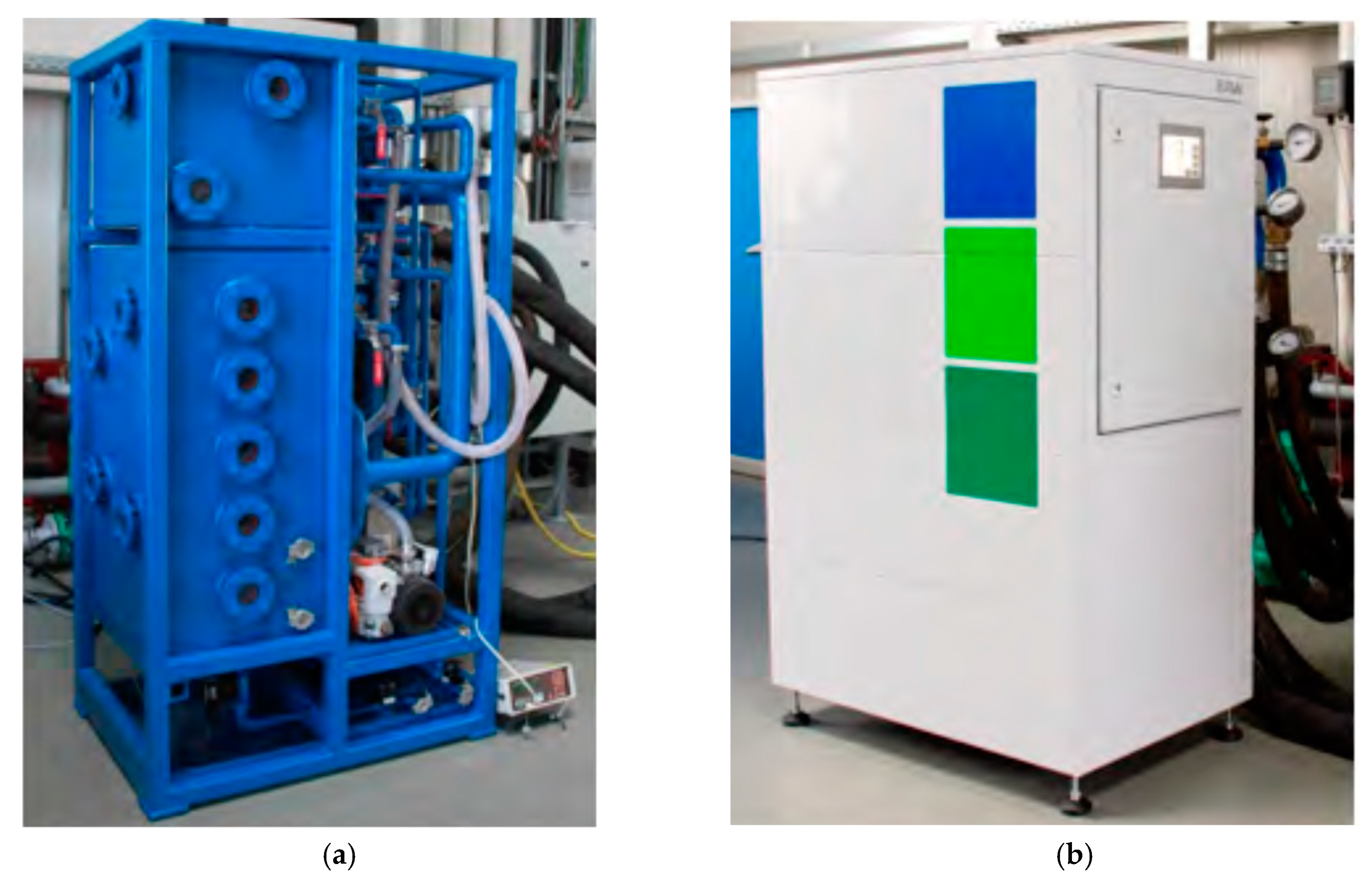
3.3. Compact Absorption Chiller: Asymmetric Plate Heat Exchanger

Typically, horizontal tube bundle heat exchangers are used as the main components of water/LiBr absorption chillers (i.e., absorber, condenser, desorber, and evaporator). Besides, designing a compact water/LiBr absorption chiller has been a challenge because of the high specific volume of water vapor which requires a relatively large heat exchanger surface area. The use of conventional plate heat exchangers (PHEs) (i.e., the same channel heights in both fluid flow sides) for water/LiBr absorption chiller technology is hampered by the high specific volume of water vapor and the low-pressure drops allowed in the heat exchanger’s vapor channels. In contrast, on the external heat carrier sides of the chiller (i.e., driving hot water, cooling water, and chilled water), small dimensions are required for better heat transfer [30]. Hence, conventional PHEs cannot be used in water/LiBr chillers because channel heights need to be different. Different channel heights create optimum heat transfer conditions on both sides of the heat exchanger (i.e., optimum heat transfer on both the vapor and the liquid sides). Accordingly, a new asymmetric PHE was designed exclusively for use in water/LiBr absorption technology by EAW Energieanlagenbau GmbH and ILK Dresden (Germany) [30,31]. This asymmetric PHE has engraved patterns that improve plate wettability and flow conditions [30]. The asymmetric PHEs developed with optimized channel heights under the operating conditions of the components of water/LiBr chillers, particularly for the absorber and evaporator, are the low-pressure side of the chiller. These PHEs can be used to manufacture absorption machines with cooling capacities up to 400 kW.
By using the newly developed asymmetric PHEs, a new generation of single-effect water/LiBr absorption chillers, shown in Figure 5, was developed and commercialized by the company EAW [32]. The company’s current product series, model WEGRACAL® Maral, includes chillers with a nominal capacity of 15 kW (Maral 1), 30 kW (Maral 2), and 65 kW (Maral 3) with thermal COP of 0.75 at chilled water supply/return temperatures of 9/15 °C [32]. In nominal conditions, the inlet/outlet temperatures of the driving hot water and heat rejection medium (water/ethylene glycol mixture (66%/34%) or water) are 86/71 °C and 27/32 °C, respectively. These chillers are activated using low-temperature hot water between 75 and 95 °C [32]. The specific chiller volume and transport weight (and operating weight) are approximately in the range 0.062–0.101 m3/kWcold and 20.9–30.0 kg/kWcold (28.3–36.7 kg/kWcold) [32]. The volume of this chiller is, on average, 40% less than the same capacity chiller using tube bundle heat exchangers.

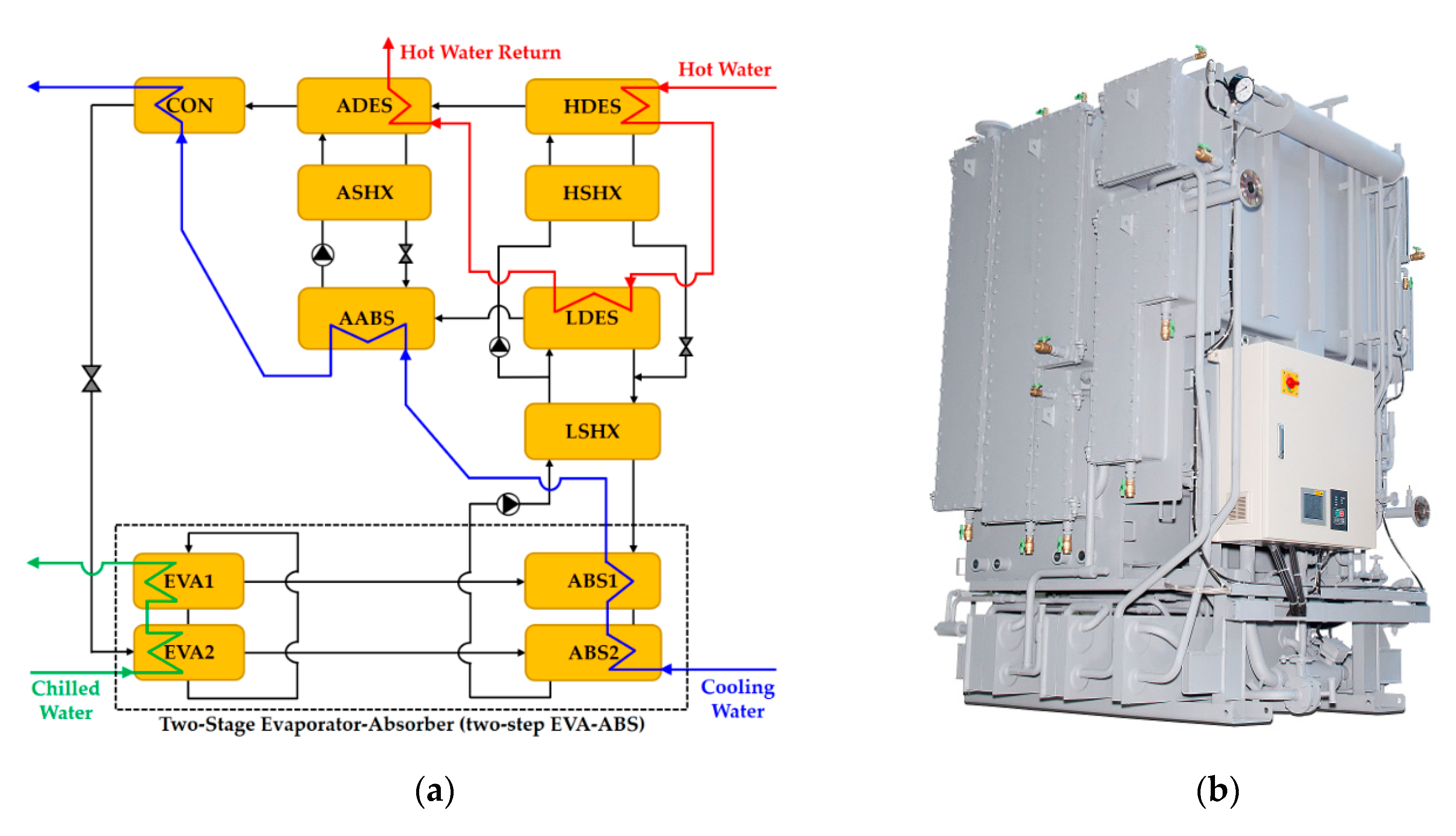
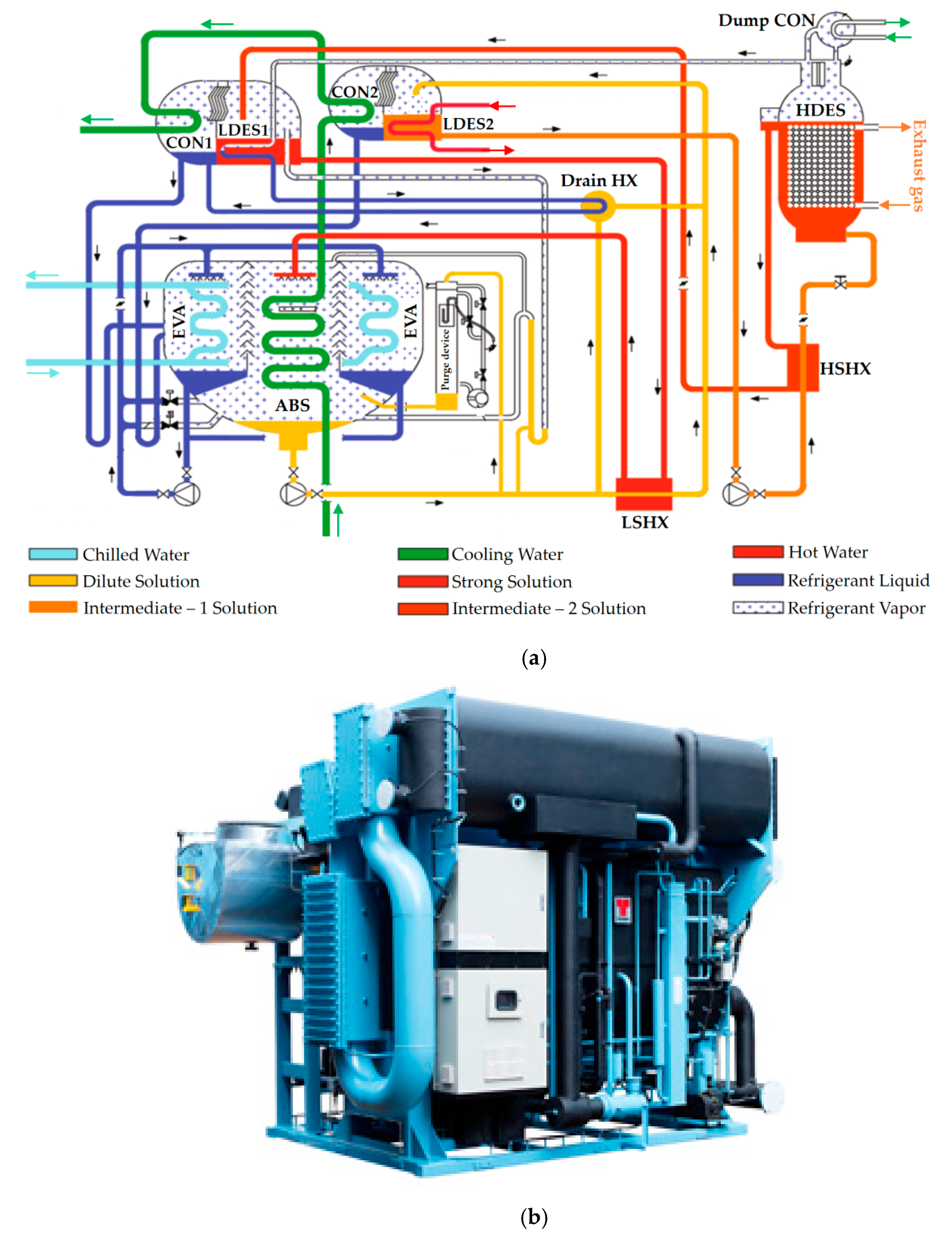
3.4. Single-Effect Double-Lift (Half-Effect) Absorption Chiller

A new absorption cycle that combines the typical single-lift (i.e., single-effect) and a double-lift (i.e., half-effect) absorption cycle was proposed and studied by Schweigler et al. [33,34] for solar energy, industrial use, and application in DH networks. It extracts unused low-temperature heat sources and uses excess heat from DH networks in summer. This cycle can use driving heat at return temperatures of about 55 °C and permits temperature glides in desorption of more than 30 K. Therefore, the return (i.e., outlet) temperature of the hot water was lower with this cycle configuration, and it increased heat intake. Thus, the cooling capacity produced from the same heat source can be larger than that of a single-effect chiller run at the same heat carrier supply temperature and mass flow. On the basis of this cycle configuration, since 2017, the company Hitachi Johnson Controls Air Conditioning Co., Ltd. has been developing and commercializing a single-effect double-lift water/LiBr absorption chiller (product type DXS) [16,35]. This product was developed under the commissioned research of the New Energy and Industrial Technology Development Organization (NEDO), Japan. The company has been conducting a research project of for NEDO on technology for the innovative use of unused thermal energy since 2015.
The single-effect double-lift absorption chiller (see Figure 6) can be operated as both a double-lift and a single-effect double-lift operation absorption chiller. Switching between these two modes of operations, half-effect and single-effect double-lift, is done using the hot water and solution valves to switch the flow directions. This absorption chiller adopts a two-stage structure for the evaporator and absorber, denoted as two-step EVA–ABS, which is applied in high-performance chillers [16]. Since the temperature of the chilled water in the first evaporator (EVA1) is lower than that of the second evaporator (EVA2), the refrigerant pressure in the EVA1 ( P low 1 ) is also lower than EVA2 ( P low 2 ). Consequently, this chiller design has four pressure levels (i.e., high-pressure ( P high ), mid-pressure ( P mid ), and two low-pressure levels ( P low 2 > P low 1 ). Hence, the chiller operates at four pressure levels by dividing the evaporator and absorber into two-step instead of three pressure levels as in the basic single-effect double-lift cycle. The driving hot water stream first enters the high-temperature desorber (HDES) and then the low-temperature desorber (LDES) and auxiliary desorber (ADES). The cooling water is connected in a series flow arrangement entering first the ABS and then the auxiliary absorber (AABS) and condenser (CON). The hot water and cooling water circulating patterns, shown in Figure 6a, were chosen to maximize the chiller’s cooling capacity. It is useful for applications of this kind of heat-driven chiller because it maximizes the specific cooling capacity per unit of hot water mass flow.
The single-effect double-lift water/LiBr chiller (Figure 6b) has a nominal cooling capacity between 176 kW and 4395 kW with chilled water supply/return temperatures of 7/12 °C for the European market and 8/13 °C for the Asian market (e.g., Japan). The inlet/outlet temperatures of the hot water and cooling water in the nominal condition are 95/51 °C and 27/33 °C, respectively, for the European market and 95/55 °C and 31/36.5 °C for the Asian market. The corresponding thermal COP of the absorption chiller is 0.72 and 0.70, respectively, for the European and Asian chiller market. This chiller product (type DXS) can extend the usable temperature of hot water (obtained from a solar thermal collector installation or DH network) to the low-temperature range and extract about twice as much heat (~200%) as the temperature difference of the single-effect absorption chiller machines. In addition to individual solar thermal cooling applications, the large temperature glide in the driving hot water and the low return temperature are especially suitable for the operating conditions in the DH networks and for delivering cold with this chiller during summer.
Another type of single-effect double-lift water/LiBr chiller driven by hot water was developed and commercialized by the company World Energy Co., Ltd. (Gunpo-si, Gyeonggi-do, South Korea) [36]. The company’s first-generation (2AB product series) of this type of absorption chiller was developed with the Korea District Heating Corporation in 2005 and was further improved in 2009. Their second-generation highly efficient chiller (2ABH product series) was developed by 2013 and certified in 2018. The advantages of the 2ABH product series are high efficiency at full and partial load operations (10% thermal COP improvement at full load, i.e., from 0.64 to 0.71); lower operating costs and footprint (14% and 20%, respectively); and a smaller cooling water pump and cooling tower (8%). The absorption cycle schematic and external view of this chiller technology are illustrated in Figure 7 and Figure 8, respectively.
In the nominal condition, the chiller delivered chilled water at supply/return temperatures of 8/13 °C with a thermal COP of 0.71 (type 2ABH) using driving hot water at inlet/outlet temperatures of 95/55 °C (i.e., a driving heat temperature glide of 40 K). The cooling water inlet/outlet temperatures were 31/36.5 °C. The nominal cooling capacity of this chiller product covers the medium- to large-scale, between 105 and 4571 kW. To date, the total installed capacity of this chiller (product type 2AB) is approximately 476.5 MW in South Korea and 47.6 MW in the rest of the world. It can lead to savings of 28 GWh of electricity per year and avoids 45 MW of power for peak demand in South Korea.

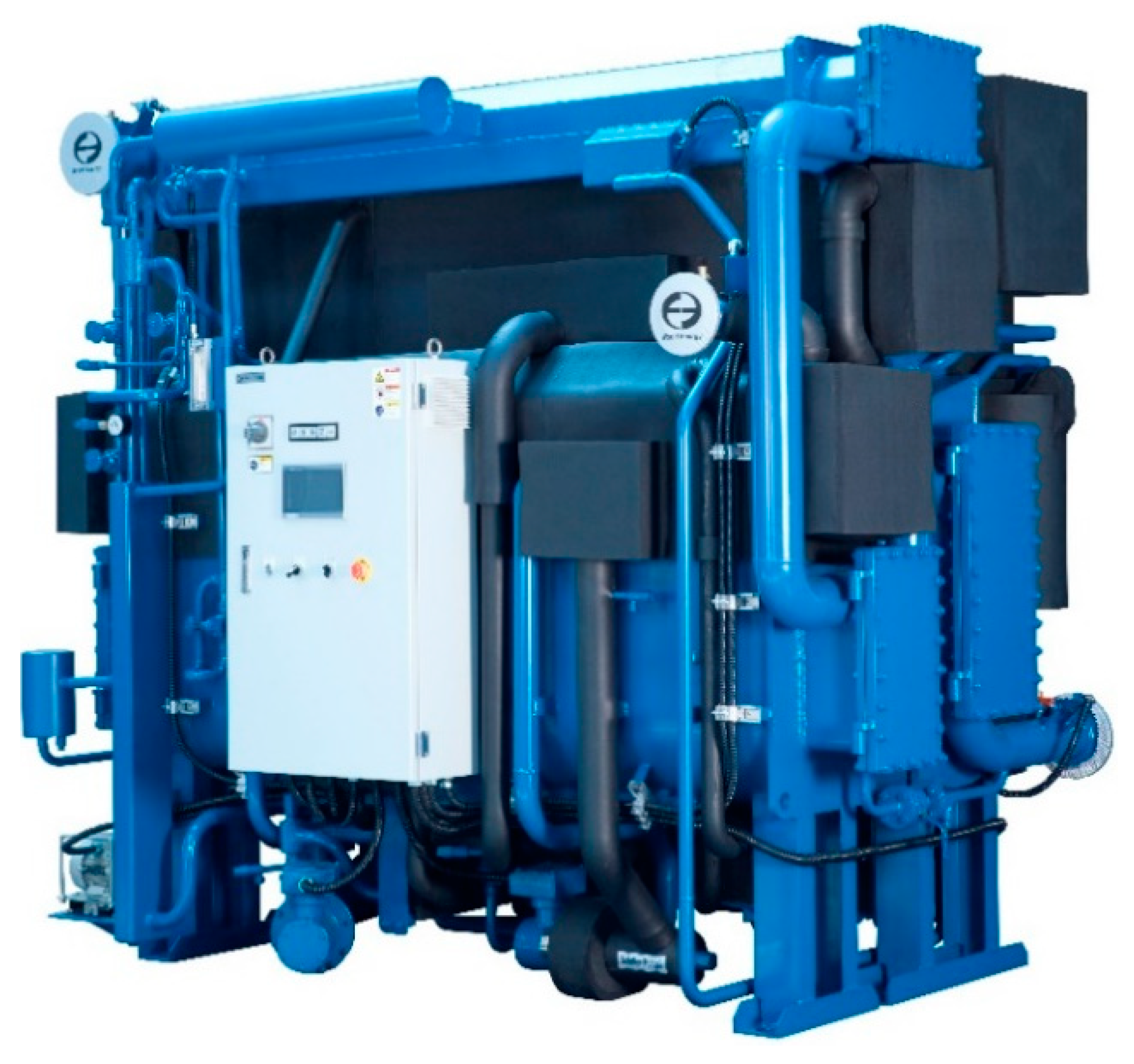
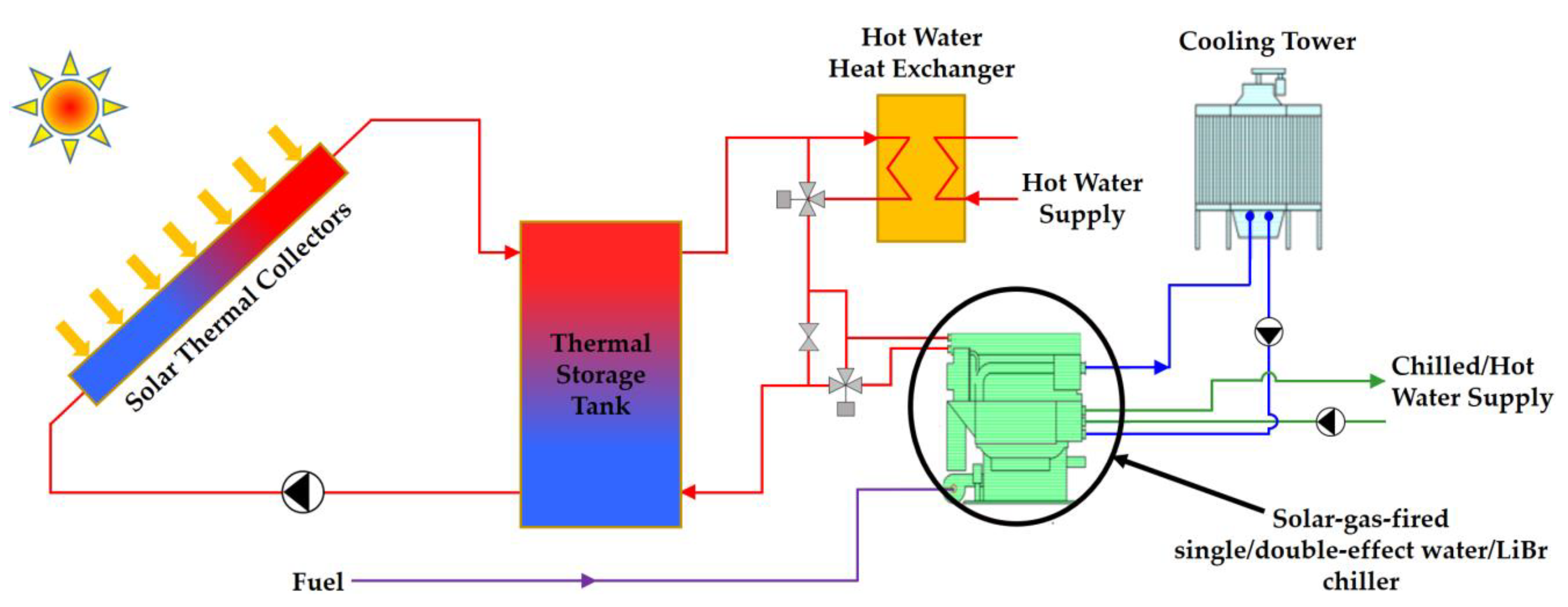
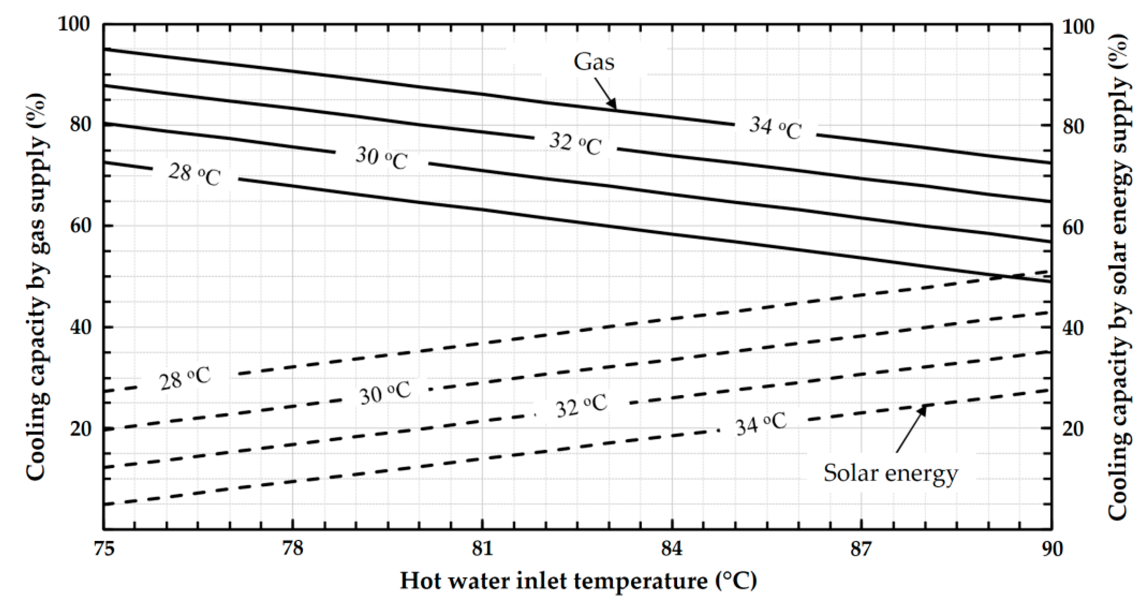
3.5. Single/Double-Effect Absorption Chiller: Solar-Gas Fired

In the conventional solar space cooling system, illustrated in Figure 1, single-effect absorption chillers are driven by low-temperature solar thermal collectors (i.e., evacuated tube and flat-plate solar collectors are mostly used). In this system, a gas-fired heater was used as a backup to supply hot water to the low-efficiency single-effect chiller (i.e., thermal COP of about 0.7–0.8 [10]). Additionally, the solar cooling system uses a complicated control system to regulate the hot water supply of the chiller per end-user cooling load and solar heat variations [37,38]. Hence, it is difficult to establish an optimum control system. To avoid these shortcomings, a new absorption chiller was exclusively designed and developed to efficiently use low-temperature solar thermal collectors for air-conditioning applications by Kawasaki Thermal Engineering Co., Ltd. in 2010 [37]. The main features of the solar cooling system concept, depicted in Figure 9, are no external backup heater; direct gas-fired desorber; and continuous priority for the efficient use of the solar resources available. This system is particularly relevant to buildings with high cooling loads and a limited area for installing solar collectors.
The crucial part of this improved solar absorption cooling system (Figure 9) is the solar-gas-fired single/double-effect water/LiBr chiller developed and commercialized by Kawasaki Thermal Engineering Co., Ltd. [39,40]. This chiller, depicted in Figure 10, functions as a single-effect chiller, a double-effect chiller, or a single/double-effect hybrid depending on the intensity of the solar irradiation and the cooling load of the end-user (e.g., buildings). It has three desorbers (shown in Figure 10a): the high-temperature desorber (HDES); low-temperature desorber (LDES); and a single-effect desorber (SDES). The chiller also operates at four pressure levels. The SDES is driven by hot water between 75 and 90 °C produced using solar heat in the nominal condition (i.e., cooling water inlet temperature at 32 °C and 100% cooling capacity). The HDES is a direct-fired-type desorber using natural gas as a fuel, the primary function of which is to support/provide backup when there is not enough solar irradiation and/or the cooling demand is high. The cooling water first enters the single-effect condenser (SCON) coupled to the SDES, then the low-temperature condenser (LCON), and finally the absorber (ABS) to collect heat rejected from the corresponding condensation and absorption processes. This series flow arrangement of the cooling water stream, from the cooling tower, enables maximum use of the solar energy available by allowing the SDES to operate at a relatively lower pressure (and, consequently, driven by a lower temperature heat). The absorption chiller has a nominal cooling capacity of 281–1055 kW at chilled water supply/return temperatures of 7/15 °C and cooling water inlet/outlet temperatures of 32/37.6 °C. The driving hot water inlet/outlet temperatures at the SDES are 90/79.5 °C for the nominal operating condition [37].
The contribution of driving heat inputs (i.e., from solar energy and gas combustion) for the production of cold is illustrated in Figure 11 at different cooling water inlet temperatures (28–34 °C) [40]. The inlet temperature of hot water was between 75 °C and 90 °C. The inlet temperature of cooling water has a significant effect on the share of the solar energy and gas consumption, e.g., each reached 50% of the cooling capacity at cooling water and hot water inlet temperatures of 28 °C and ~ 89 °C, respectively. Also, the minimum hot water inlet temperature was between ~ 59 °C and 72 °C, the cooling water inlet temperature was between 28 °C–34 °C, and the chilled water was supplied at 7 °C with a cooling capacity of 239 kW [40]. This hybrid chiller operated at nearly 55% of its nominal capacity using only solar energy to supply chilled water at 7 °C. Besides, in order to be economically competitive, the solar cooling system has to work with high solar fraction (Equation (3)) and the primary energy rates ratio (Equation (5)) must be higher than one. Therefore, the solar-gas-fired single/double effect water/LiBr absorption chiller was designed and developed to address this cost effectiveness using optimized solar energy use and gas consumption.
In parallel, Thermax Ltd. developed and commercialized absorption chillers designed on the basis of the single/double-effect technology to enable maximum use of heat sources at two-temperature levels with a single machine [42]. The chiller is known as a multi-energy driven chiller (2D Series) in which the high-temperature heat source is used in the double-effect desorber, while the low-temperature heat source is used in the single-effect desorber. In this type of chiller, high-temperature steam (3.92 to 9.81 bar), exhaust gas (350 to 600 °C), and hot water (150 to 180 °C) are supplied to the high-temperature desorber, whereas steam (up to 2.94 bar) and hot water (80 to 95 °C) are supplied to the low-temperature desorber. Additionally, it has a backup direct oil/gas-fired system. For instance, in the EJ Series product line (see Figure 12), engine exhaust gas and jacket cooling water are used in high-temperature and low-temperature desorbers, respectively, to drive the absorption chiller. The nominal cooling capacity of the commercially available absorption chiller of this type is between 175 and 12,300 kW, medium- to large-capacity, with chilled water supplied at temperatures up to −1 °C and brine supplied up to −2 °C. It has a thermal COP between 1.1 and 1.2. The main differences between the Thermax EJ Series and Kawasaki’s hybrid chiller are the type of high-temperature desorber (indirectly driven by exhaust gas and directly gas-fired, respectively) and the flow arrangement of the absorber and condenser cooling water connections (see Figure 10a and Figure 12a).
The above small-to-large capacity of newly developed water/LiBr chiller technologies with special features suitable for solar space cooling applications are summarized in Table 1.

4. Prototypes of Absorption Chillers

This section focuses on the laboratory and pre-industrial prototypes developed with various features to effectively use heat from solar energy for space cooling applications. These features include heat rejection without cooling towers (i.e., direct and indirect-air cooled), size compactness, operational flexibility, and a large temperature glide in the driving heat source. These absorption chiller prototypes use conventional working pairs (i.e., ammonia/water and water/LiBr mixtures) as well as non-conventional working pairs such as ammonia/LiNO3. This section is divided into two parts: single-stage absorption chillers and advanced absorption chiller prototypes.

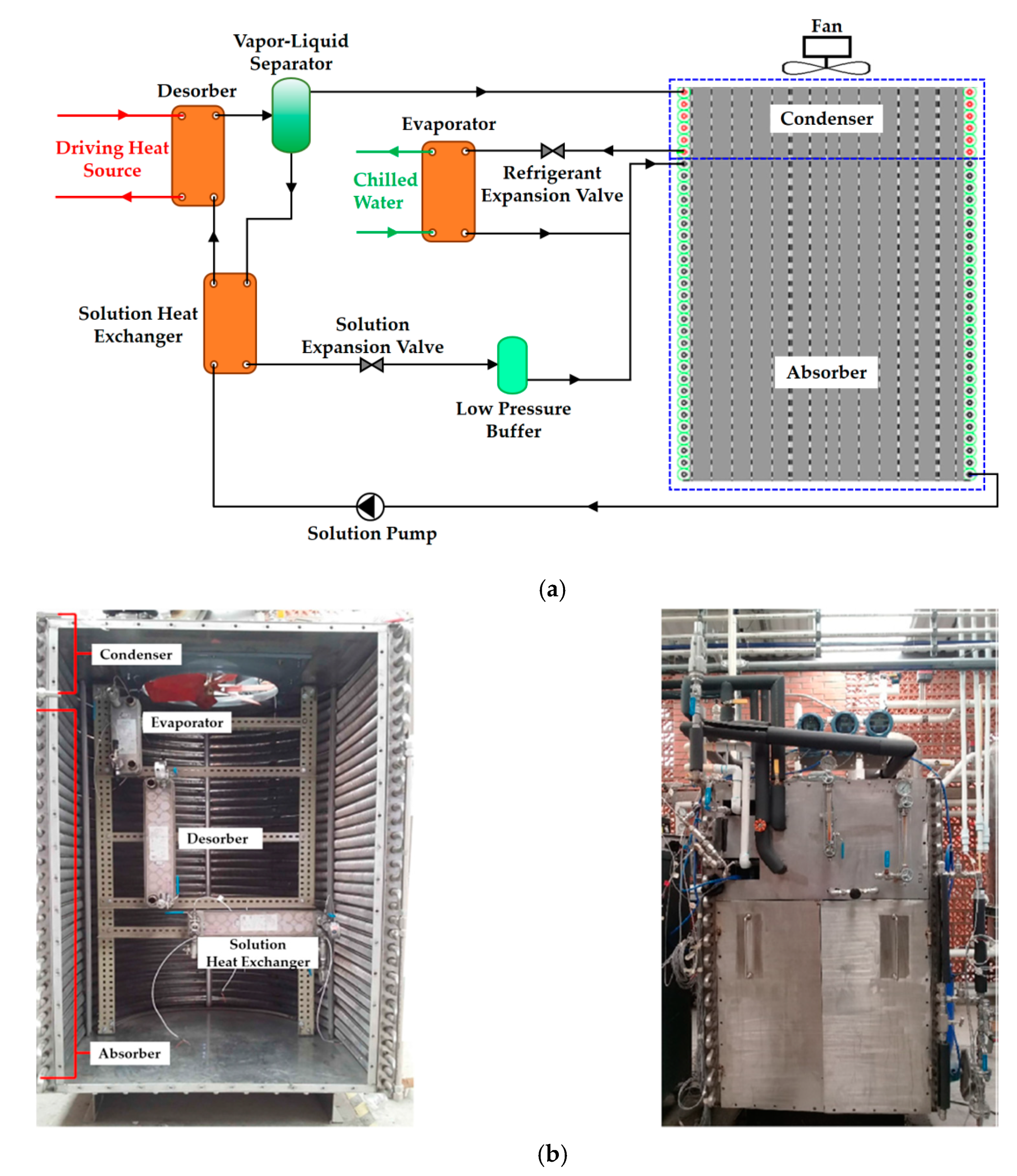
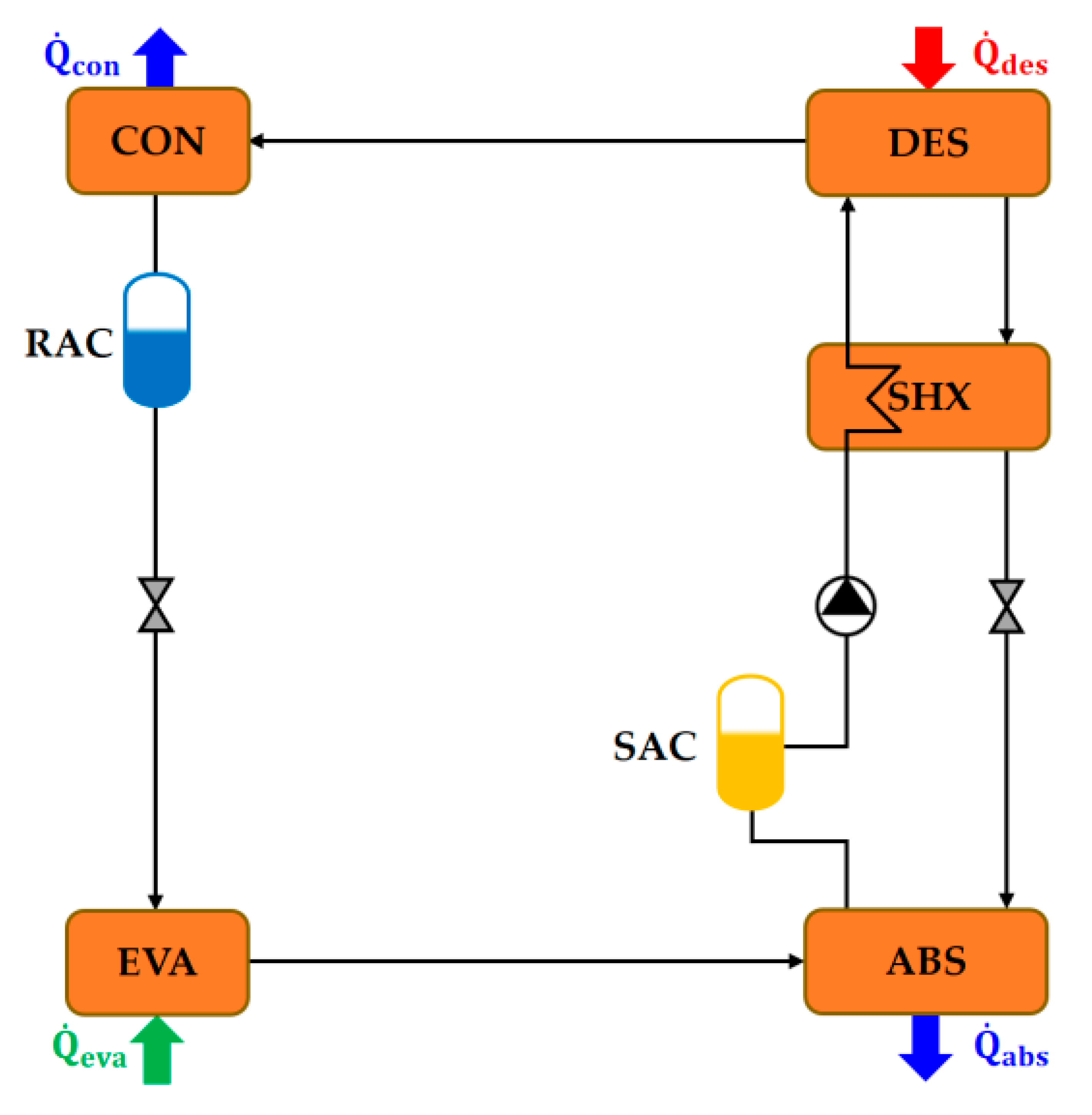
4.1. Single-Stage Absorption Chillers

4.1.1. Ammonia-Based Working Pairs

It is a common practice to use plate heat exchangers (PHEs) in vapor compression chillers because of their compactness, lower system refrigerant charge, and reduced cost. Consequently, absorption chillers built with PHEs can be smaller and cheaper than conventional absorption chillers. Besides, PHE-based chillers have a dynamic behavior quite unlike that of other absorption chillers, especially water/LiBr chillers which require larger heat exchangers with higher thermal inertia [48]. Therefore, the use of PHEs to build absorption chillers has been one the main advances in the last two decades, particularly for refrigerant ammonia-based absorption chillers.
To date, the use of PHEs to reduce the size (i.e., volume) of ammonia/water-based absorption chillers is limited. A few laboratory prototypes have been built using PHEs as the main components of the ammonia/water absorption chiller [49,50]. The prototype of a 5 kW single-effect ammonia/water chiller was developed using brazed PHEs for solar cooling applications [50]. The PHEs were used as the desorber, rectifier, and absorber in which the falling film absorption process occurs. Under experimental test conditions, this prototype delivered 4.2 kW of cold with a thermal COP of approximately 0.65 when the heat source, heat sink (for absorber and condenser), and chilled fluid inlet temperatures were 80 °C, 27 °C, and 18 °C, respectively.
Another prototype of a single-effect ammonia/water chiller was built using commercially available Alfa Laval™ PHEs with its main components in vertical alignment [49]. The two types of stainless-steel plate heat exchangers used in this prototype were Alfanova 52 (40 plates) and Alfanova 27 (20 plates). The Alfanova 52 model was used for the absorber, desorber, and solution heat exchanger, whereas Alfanova 27 was used for the condenser and evaporator. All the other parts of the prototype, including the ½ inch nominal diameter and 0.4 m long finned tube rectifier, were built using stainless steel to avoid corrosion due to the presence of ammonia. The overall volume of the prototype was approximately 0.8 m3. Its performance was investigated at driving hot water and cooling water inlet temperatures between 85 °C and 105 °C and 20 °C and 32 °C. The corresponding maximum cooling capacity and thermal COP attained in these operating conditions were ~ 2.6 kW and 0.61. Both of these values were calculated using internal measured variables [49]. An evaporation temperature of approximately 19 °C was reached so that the compact chiller prototype could operate to serve a range of applications including air conditioning and refrigeration.
It has been suggested in the literature that the ammonia/LiNO3 mixture could be used as an alternative to alleviate some of the drawbacks associated with the conventional working pairs (i.e., ammonia/water and water/LiBr), especially in solar cooling applications [51]. The thermophysical properties of ammonia/LiNO3 that are useful for performance analysis and designing absorption chillers can be found elsewhere [52,53,54,55,56]: vapor pressure, density, heat capacity, and viscosity in Libotean et al. [52,53]; thermal conductivity in Cuenca et al. [55]; and enthalpy and entropy with absorption chiller’s energy and exergy analysis of single-effect ammonia/LiNO3 absorption cycle in Farshi et al. [56]. The ammonia/LiNO3 absorption chiller has performed better than the water/LiBr absorption chiller at high heat rejection temperatures, and it does not present the risk of crystallization in the range of working temperatures for space cooling applications. Moreover, low-temperature heat from flat-plate solar collectors, between 80 and 90 °C, can activate the chiller [51]. It has also been shown that the use of ammonia/LiNO3 instead of water/LiBr has advantages for air-cooled absorption chillers. For example, at an ambient air temperature of 41 °C the ammonia/LiNO3 absorption chiller can deliver a cooling effect with no risk of the solution crystallizing (64% of its nominal cooling capacity at an ambient temperature of 35 °C [57]). Compared to the ammonia/water mixture, ammonia/LiNO3 can be used to design and develop a simplified absorption chiller by avoiding the need for desorbed vapor rectification and reducing the refrigerant charge. Besides, ammonia/LiNO3 makes it possible to operate the chiller at high heat rejection temperatures and a minimum of 10 °C below the desorption temperature [57].
Between 2006 and 2011, a laboratory prototype and two pre-industrial small capacity ammonia/LiNO3 absorption chillers were designed and manufactured with the close collaboration of the CIATESA (Compañia Industrial de Aplicaciones Termicas S.A)–CIAT group and the CREVER research group of the URV (Universitat Rovira i Virgili) [48,51,57,58,59]. The pre-industrial prototypes are air-cooled and water-cooled single-effect absorption chillers. In these prototypes, all the components are made of brazed PHEs. A patented unique distribution device was also used to mix the ammonia vapor and the weak solution at the entry port of the absorber [59]. The schematic diagram of the prototype’s cycle configuration is illustrated in Figure 13. The prototype was designed for a nominal cooling capacity of 10 kW at a chilled water supply temperature of 15 °C for air conditioning applications. The corresponding hot water and cooling water inlet temperatures are 90 °C and 37.5 °C in the nominal design conditions.
The prototypes were tested under different operating conditions. The air-cooled prototype chiller was experimentally tested at hot water and ambient temperatures of 90 °C and 35 °C. The cooling output was ~ 9.3 kW at a chilled water supply temperature of 15 °C with an electrical COP of about 6.5 for a fan speed of 600 rpm [57]. The chiller is also capable of delivering 64% of its nominal capacity at an ambient air temperature of 41 °C, which makes it highly applicable in hot climate conditions. According to the test carried out for the water-cooled prototype, an output of ~ 12.9 kW cooling was obtained at a chilled water supply temperature of 15 °C and an electrical COP of ~ 19.3 [57]. The hot water and cooling inlet temperatures were set to 90 °C and 35 °C, respectively. The pre-industrial prototype of the air-cooled ammonia/LiNO3 absorption chiller manufactured by the company CIATESA is shown in Figure 14.
The single-effect ammonia/LiNO3 laboratory prototype was built using Alfa Laval™ PHEs, and all its main components were used in a vertical configuration [61]. Both Alfanova 52 and Alfanova 27 were made of stainless steel and were also used in this prototype to avoid corrosion because of ammonia and LiNO3. The prototype was experimentally tested at hot water and cooling water inlet temperatures between 80 °C and 95 °C and 20 °C and 32 °C, respectively. In this operating range, the prototype reached a cooling capacity of 3.1 kW at chilled water supply temperatures as low as 6 °C and a thermal COP of ~ 0.62. Using these PHEs, a compact ammonia/LiNO3 chiller was developed with an overall prototype volume of approximately 0.7 m3. It was significantly smaller (by approximately 57% [62] and 71% [63]) than any previous single-effect ammonia/LiNO3 prototype that used PHEs for some of their components (i.e., condenser, evaporator, and solution heat exchanger).
An air-cooled single-effect ammonia/LiNO3 chiller (illustrated in Figure 15a) was developed at the Universidad Nacional Autónoma de México (Mexico) [64]. In this prototype, the heat rejected during the absorption and condensation processes was removed by using finned tubes. An electric motor driven axial fan was used to circulate the air through the absorber and condenser. The desorber and solution heat exchanger were made of 40 and 20 Alfanova 52 plates, respectively, whereas the evaporator was made of 20 Alfanova 27 plates. The overall size of the prototype (shown in Figure 15b) was approximately 2.5 m3. The prototype delivered a cooling output of up to 3.4 kW and a thermal COP of up to 0.33 when operated at a driving hot water temperature of between 80 °C and 100 °C. It supplied chilled water as low as 2.6 °C and was operated without a cooling tower due to the use of an air-cooled heat rejection system.

4.1.2. Water/LiBr Working Pair

Water/LiBr is the most commonly used working pair in absorption chillers because of its superior properties. However, water/LiBr absorption chillers have some well-known drawbacks that ammonia/water absorption chillers do not such as crystallization and operation under vacuum. The thermophysical properties of the water/LiBr mixture can be found in the literature [65,66,67,68].
A 2 kW air-cooled single-effect water/LiBr chiller was developed and experimentally tested at the Heat and Mass Transfer Technological Center (CTTC) at the Universitat Politècnica de Catalunya (UPC) in Terrassa, Spain [69]. To define the chiller’s control strategy [69], a numerical model was developed to predict the thermal behavior of this absorption chiller under the transient mode of operation and its interaction with other system components (e.g., solar thermal collectors and circulation pumps). The model developed was validated using performance data (i.e., thermal COP and cooling capacity) obtained from the experimental tests carried out at CITC-UPC [70]. They also carried out numerical simulations using the NEST (Numerical Edifice Simulation Tool) platform (an in-house developed object-oriented numerical tool) which focused on the performance and key drawbacks associated with water/LiBr absorption chillers (e.g., crystallization) and geometrical aspects. The outcomes of these numerical simulations and experimental studies also helped to understand and design the control system’s strategies.
On the basis of the investigation of the 2 kW air-cooled chiller, a pre-industrial single-effect water/LiBr prototype with a cooling capacity of 7 kW was designed and developed at the CITE-UPC laboratory. This prototype has an absorber and a condenser that are directly air-cooled. Both prototypes, with capacities of 2 kW and 7 kW, were part of a virtual laboratory, and all experimental data showed that there was little risk of LiBr crystallization. Furthermore, the dynamic numerical model was modified to improve its accuracy and reliability [71]. The model was improved largely by mass transfer calculations based on the author’s experience of the falling film absorption process. The heat and mass transfer parameters used in the model developed were validated using the steady-state experimental data obtained from the laboratory prototype with a cooling capacity of 2 kW, and there was reasonable agreement among the thermal COP values (with the capacity being slightly under-predicted). The numerical model was used to predict the performance of the 7 kW air-cooled water/LiBr prototype. However, the model predicted the cooling capacity to be 81% (i.e., 5.7 kW) of the expected cooling capacity even though the heat exchangers of the chiller had been designed to provide the nominal capacity of 7 kW [71].
The transient model of the chiller was validated using the experimental data obtained under steady-state conditions. For the 2 kW air-cooled chiller, there was good agreement between the numerical and experimental results with small discrepancies in semi-empirical information used in the model. The 7 kW chiller was also experimentally validated at UPC-BarcelonaTech [72]. The model was used to evaluate the absorption chiller as well as the various control strategies (e.g., on/off versus fuzzy logic). The price of the air-cooled water/LiBr chiller developed (with the collaboration of Termo Fluids S.L., Spain) with a capacity in the range 7–11 kW and a thermal COP of ~ 0.7, and the rest of installation, without the solar collector field, is estimated to be about 15,000 Euro (1800–2150 Euro per kW of cold).

4.2. Advanced Absorption Chillers

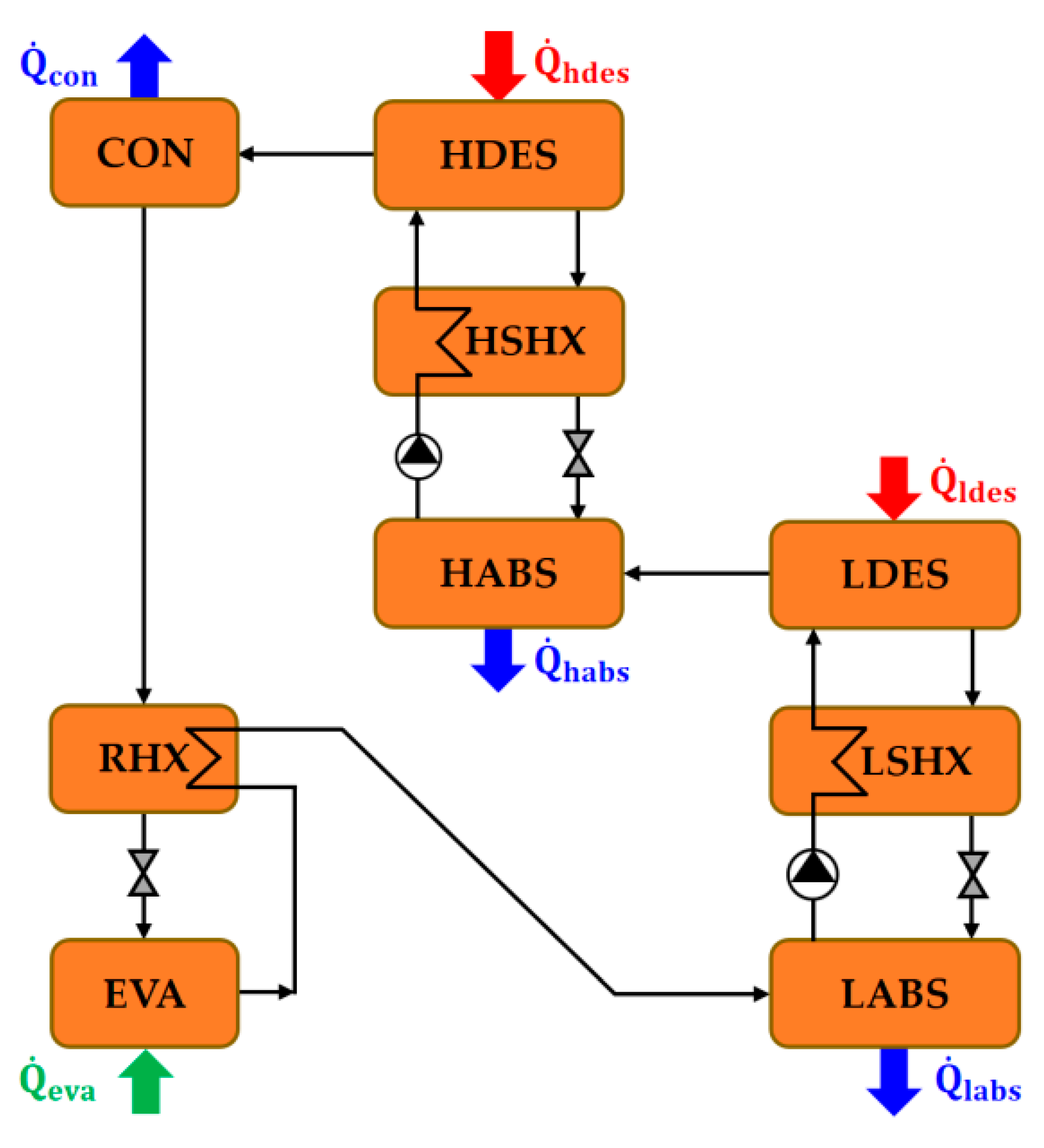
4.2.1. Double-Lift Absorption Chillers

As previously mentioned in Section 3.2., some of the recent developments in single-effect water/LiBr technologies have extended the heat source temperature glide by about 18 K (e.g., 90 to 72 °C) in nominal operating conditions. Additionally, using a single-effect water/LiBr chiller driven by hot water at 95 °C makes it possible to extract heat up to 75 °C (i.e., a 20 K temperature glide) to deliver chilled water with supply/return temperatures of 7/12 °C at cooling water inlet/outlet temperatures of 27/33 °C [16,35]. To be able to use heat sources at temperature levels that cannot activate a single-effect chiller, it is often necessary to use a double-lift absorption chiller to produce chilled water [73]. Typically, hot water at 70 °C is compatible with double-lift water/LiBr chillers. Also, an ammonia/water double-lift refrigerator was built and successfully operated in Alaska (United States) in the 1990s, driven by the diesel engine jacket cooling water at 75 °C to deliver ~9071.8 kg per day of flake ice for a remote community [74].
The prototype of a double-lift ammonia/water absorption chiller system based on a direct air-cooled absorber and condenser has also been developed and experimentally studied [75,76]. In this prototype, a vertical shell-and-tube falling-film heat exchanger was used as a desorber and the vapor generated was passed through a rectifier made of a pall ring packed bed with a solution cooled coil. A shell-and-tube vertical flow countercurrent heat exchanger was used as an evaporator. The absorber and condenser were made of steel tube coils with vertical aluminum fins in which the tubes were horizontal and arranged in one row, all of which was cooled by a 500 mm axial fan. The prototype was tested at chilled water inlet/outlet temperatures of 12/7 °C, a driving hot water temperature between 80–90 °C and an air temperature between 22 and 38 °C. The cooling capacity of the prototype was 2.5 kW at air and inlet hot water temperatures of 30 °C and 90 °C. The corresponding thermal and electrical COPs were 0.3 and 10, respectively. The chiller responds quickly to any variation in operating conditions. With this design, the chiller prototype is well-suited to recovering waste heat from internal combustion engines because of its limited temperature glide (e.g., 5 °C) in the driving heat source. However, for solar cooling applications, the heat transfer in the desorber could be optimized to allow a low flow strategy for the driving circuit. This could be advantageous for the overall electrical COP of the system.
The new concept of a single-/double-lift (i.e., single-/half-effect) ammonia/water absorption chiller was built by adapting the commercial product PinkChiller PC 19 [77,78]. The Pink PC 19 commercial chiller had been developed using tube bundle heat exchangers for the absorber, desorber, and condenser, whereas the falling film-type heat exchanger was used for the evaporator. Thereby, it limits the size of the chiller and incurs high production costs because of the limitations on the assembly and welding of the heat exchangers. Hence, the single-/double-lift chiller is based on redesigning the Pink PC19 chiller and using flat PHEs for its main components (i.e., absorber, condenser, desorber, and evaporator). The absorber design was optimized using a new type of injector nozzle, balancing the water flow between the two solution loops and adapting the internal control strategy (i.e., solution pump control). This new absorption chiller is switchable between single-lift (single-effect), double-lift (half-effect), and single-/double-lift modes with a cooling capacity of 20 kW in the single-effect mode. When the chiller was experimentally tested (under steady-state and dynamic operating conditions), the performance was stable over a wide range of operating conditions under each mode of operation. The schematic diagrams of the chiller cycle illustrating the single-effect and half-effect configurations are depicted in Figure 16 and Figure 17, respectively. The chiller was designed to drive hot water inlet/outlet temperatures of 90/70 °C, chilled water supply/return temperatures of 6/12 °C, and heat rejection inlet/outlet (absorber and condenser) temperatures of 40/45 °C.
The experimentally determined nominal cooling capacity of the single-lift and double-lift mode of operations is about 18.4 kW and 10.6 kW, respectively, with a corresponding energy efficiency ratio (i.e., thermal COP) of approximately 0.57 and 0.27. These performance values (i.e., cooling capacity and thermal COP) are for the following nominal operating conditions: the heat source, cooling water, chilled water inlet temperatures, and flow rates are 85 °C and 4.5 m3/h, 20 °C and 6.5 m3/h, and 12 °C and 3 m3/h, respectively. The main advantages of the new concept implemented in this prototype are that dry cooling towers can be used so that maintenance and costs are reduced. Moreover, if this chiller is to be implemented effectively in solar-driven refrigeration systems, they must focus on high production and, thus, a high cooling capacity of the chiller. Finally, the experimental and numerical results obtained from this chiller prototype led to the development of an economical, scalable, flexible, and reliable ammonia/water absorption chiller.

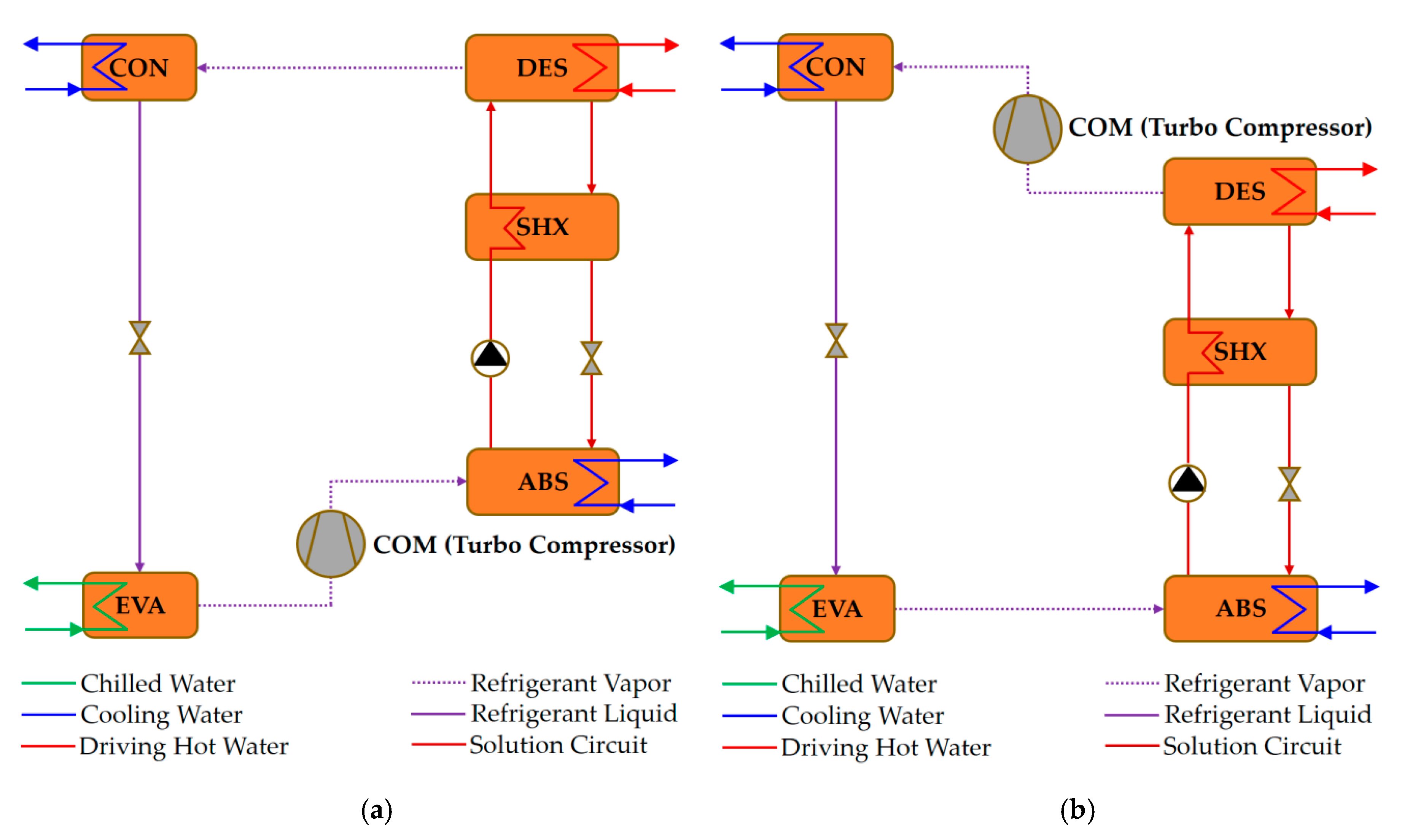
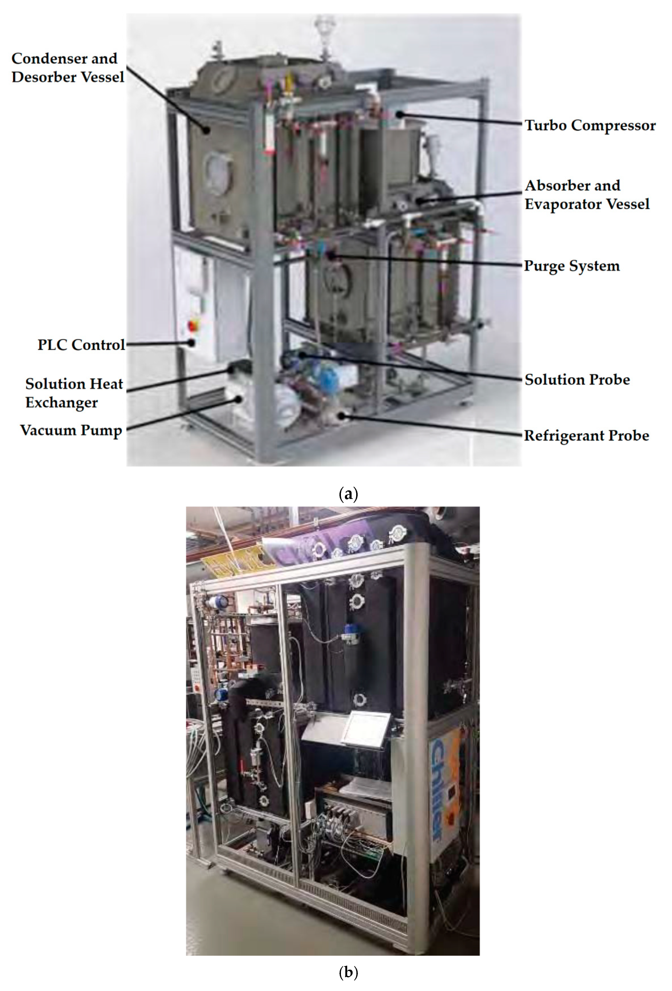
4.2.2. Mechanical Compressor Assisted Absorption Chillers

The application range of conventional absorption chillers is restricted by the properties of the working fluid (e.g., water/LiBr) used in the chiller. For instance, the driving heat temperature needs to be higher than the required minimum activation temperature, and the chiller has a limited temperature lift. Accordingly, for applications such as solar cooling, the absorption chiller needs to be oversized to adjust to a low-grade driving heat source [79]. Moreover, since the temperature lift of water/LiBr-based chillers is limited, dry cooling towers cannot be used in this type of absorption chiller. Therefore, to extend the operating range of absorption chillers, a hybrid refrigeration cycle is formed by combining the absorption cycle and mechanical compression process in a series or parallel flow arrangement. The hybrid mechanical compression combined with the absorption cycle benefits to overcome the restrictions of the working fluid characteristics. These benefits include higher heat rejection temperatures for dry cooling under hot climate conditions, lower driving heat inlet temperatures so that low-temperature solar or other types of heat can be used (e.g., waste heat), and greater cooling capacity during peak load conditions [79,80,81,82,83].
The integration of a mechanical compressor (either between EVA and ABS (Figure 18a) or between DES and CON (Figure 18b)) leads to operational flexibility and boosts the cooling capacity for a single-effect water/LiBr absorption chiller. Thereby, operating conditions could be more extreme (e.g., high heat rejection temperature, >35 °C) and chiller designs could be more compact and cost-effective using the compressor-assisted absorption chiller. To date, the lack of a suitable compressor for refrigerant water vapor has been a bottleneck for implementing such a hybrid water/LiBr absorption-compression chiller. The properties of water (i.e., low specific density, high-pressure ratio, and high vapor outlet temperature) represent a significant challenge for the design of the compressor. However, high-speed turbo vapor compressors for refrigerant water have recently been put on the market by some companies in Europe and Asia because of significant progress in new materials and manufacturing techniques which have improved geometries and increased impeller tip speed (up to 600 m/s) [83].
Accordingly, the technical proof of concept of the mechanical compressor-assisted single-stage water/LiBr absorption chiller unit has become feasible, and a laboratory prototype of the unit has been built and tested at the Munich University of Applied Sciences (Germany) [82]. This hybrid chiller unit with a size of 2.6 m3, depicted in Figure 19, was developed for a capacity of 15 kW with the chilled water supply at 6 °C and tested under various operating conditions. The maximum driving heat source and cooling water inlet temperatures are 90 °C and between 35–40 °C, respectively. The main components of this prototype (i.e., absorber, condenser, desorber, and evaporator) were built using falling film over the side-by-side horizontal tube bundle heat exchangers [82]. This type of heat exchanger ensures superior thermodynamic and fluid dynamic performances as well as scalability to higher chiller capacities [82]. Besides, the unit is equipped with a purge system for the non-condensable gases to ensure continuous equilibrium test conditions.
The chiller unit was designed to ensure undisturbed transonic vapor flow into the compressor. The risk of the entrainment of water droplets and flow losses was also minimized. The turbo compressor’s implementation was based on the numerical analysis carried out and can be applied up to a pressure ratio of 3.5 and a maximum number of revolutions of 90,000 rpm. The isentropic efficiencies were approximately 60% for pressure ratios of less than 3.0 [83].
The research into laboratory and pre-industrial prototypes of absorption chillers that can effectively use solar energy is summarized in Table 2.

5. Research Trends and Opportunities

In recent years, the research and development of absorption chillers has focused mainly on such critical features as heat rejection using an air-cooled unit, system compactness, large driving heat temperature glides, and high overall system efficiency (i.e., high electrical and thermal COPs). Also, small-capacity chillers may be of interest for use in solar air conditioning applications in residential and small commercial buildings. Although in the past decade, several new developments have been put on the market (Section 3), further significant progress must be made to compete with systems based on a vapor-compression chiller. Accordingly, research into the development of new absorption chillers has been taken three main directions in recent years:
Extension of operational limit: heat rejection and driving heat temperatures
Heat rejection temperature: the use of water/LiBr in absorption chillers limits the absorber heat rejection temperature because of crystallization [85]. Therefore, increasing this temperature limit means that heat is rejected to the ambient air (without using cooling towers) and air-cooled absorption chillers perform well. Various approaches have been discussed in the literature, among which are solubility enhancement using anti-crystallization additives (e.g., ionic liquids [86,87] and salts); absorber design improvement (enhanced heat and mass transfer processes); absorption cycle modification (using thermal/mechanical compression booster to increase the absorber pressure); and internal control-via-increasing evaporator temperature.
Driving heat temperature: the return temperature of the driving heat stream can be reduced (i.e., higher temperature glide) with an improved desorber design and advanced cycle configurations.
  • Compactness: the absorber and desorber of market available chillers are mostly based on falling film configurations in which the horizontal and vertical tube falling film exchangers are the components that have most been implemented and studied [88]. Nevertheless, this type of design has downsides, including maldistribution of the film on the exchanger surface, which disturbs flow uniformity at low Reynolds number [89] and results in dry patches on the plate surface (non-wetted areas) and thick liquid films (wetted areas). Therefore, it reduces the absorption and desorption rates, and decreases the useful absorber and desorber surfaces, which results in bulky components. This is especially crucial for the absorber since it is the least efficient component of the chiller because of the low mass diffusion coefficient of water vapor in the solution of water/LiBr [90]. Additionally, heat transfer from wetted areas is also lower than from perfectly wetted surfaces because of the greater thickness of the film. Therefore, recently, the use of (i) plate-type falling film absorbers [88] and (ii) membrane contactors in the absorber and desorber have been proposed and investigated for the development of compact and inexpensive water/LiBr [91,92,93,94,95,96,97] and ammonia/water [98,99] absorption refrigeration systems, particularly in a small capacity range. The use of a plate-type falling film configuration in the absorber and desorber of the absorption chiller can significantly enhance the absorption and desorption rates, which can make these devices much more compact and more efficient for water/LiBr-based mixtures.
  • Control strategy and operation: It is common practice in the control and operation of absorption chillers to use fixed volume flow rates for external heat carrier fluids (i.e., driving heat, heat rejection, and chilled water streams). These volume flow rates and the fan speed of the heat rejection unit are fixed at the values for the nominal design condition (i.e., nominal thermal powers). This operation strategy leads to parasitic electricity consumption dominating the chiller’s part-load operation. Consequently, the benefit of low electrical energy consumption for absorption chillers is reduced, which leads to low electrical efficiency (i.e., low electrical COP). Moreover, theoretically, reducing the pump/fan volume flow rate by decreasing the pump/fan speed about 50% reduces electricity consumption by 87% [100]. Therefore, new control and operation strategies can be implemented by actively controlling external volume flow rates via variable speed pumps and fans. By so doing, the whole system consumes less electricity and electrical COPs are higher. This new type of control strategy has already been applied in field tests with newly developed absorption chillers, new-AHP, in solar and tri-generation (CHP plants) applications [24,100]. Because of the intermittent nature of the solar resource and the variation in the cooling load during the day (and also the year), these newly developed absorption chillers need to be controlled if they are to perform optimally and operate safely. Hence, in recent years, control strategies have been developed on the basis of chiller performances in field tests and simplified models (such as the characteristic equation method) to describe the full and partial load operation of the chillers.

6. Concluding Remarks

The use of solar energy for space cooling applications is an attractive green solution that can reduce the strain on the electrical grid, especially at peak hours, while decreasing fossil fuel consumption and associated greenhouse gas emissions. Another main driver for the use of a solar cooling system is the concurrence of solar radiation and air conditioning needs in most buildings. Solar absorption cooling systems can considerably reduce the adverse global environmental effect of the demand for space cooling. However, most conventional market available absorption chillers cannot effectively use the solar resource because they are costly, bulky, and consume a significant amount of electrical energy for the parasitic loads.
Recently, new water/LiBr absorption chillers with unique technical features have emerged on the global market. They were described and thoroughly discussed in the present article. Among these newly developed chillers are an air-cooled small capacity chiller of 2.5 kW; compact chillers designed using asymmetric plate heat exchangers (15, 30, and 65 kW nominal capacities); highly-efficient compact absorption heat pumps for cooling and heating applications (50, 160, and 500 kW nominal cooling capacities); single-effect double-lift chillers (with 40 K and above temperature glide in the driving heat); and solar-gas-fired single/double-effect absorption chillers. Besides, pre-industrial and laboratory prototypes of ammonia/LiNO3 absorption chillers using typical symmetrical plate heat exchangers have been developed and tested in different operating conditions. Furthermore, water/LiBr chillers are enabled to adapt to extreme operating conditions (e.g., high heat rejection temperatures, >35 °C) using R718 turbo compressor boosted absorption chiller configurations. This concept was applied and tested using a 15 kW exclusively designed water/LiBr single-effect absorption chiller with a turbo compression booster and showed the desired operational flexibility.
Additionally, because of the intermittent nature of the solar resource and the variation in the cooling load during the day (and also the year), absorption chillers need to be controlled and operated safely if they are to perform optimally in full and partial load operations. Thus, active control strategies based on the variable volume flow rates of the external heat carrier fluid circuits, mainly for heat rejection, can reduce the parasitic electricity consumption of the overall system (i.e., higher electrical COP). Finally, using these newly developed absorption chillers with an advanced control strategy could help develop highly efficient, cost-effective, and robust solar thermal cooling solutions which can mitigate the unsustainable impact of the future global demand for space cooling.

Author Contributions

Review of literature, writing—original draft preparation, writing-review and editing, D.S.A.; supervision, review, resources, A.C. All authors have read and agreed to the published version of the manuscript.

Funding

Universitat Rovira i Virgili: Martí-Franquès postdoctoral research fellowship 2018 (Ref.: 2017PMF-POST2).

Acknowledgments

Dereje S. Ayou gratefully acknowledges the Universitat Rovira i Virgili for the Martí-Franquès postdoctoral research fellowship 2018 (2017PMF-POST2). John F. Bates, coordinator of the language service at the Universitat Rovira i Virgili, is acknowledged for his editing contribution to the final version of the manuscript.

Conflicts of Interest

The authors declare no conflict of interest.

Nomenclature

AABSauxiliary absorber
ABSabsorber
ABS-HXabsorber heat exchanger
ADESauxiliary desorber
AHPabsorption heat pump
ASCair-cooled small capacity water/LiBr chiller
ASHXauxiliary solution heat exchanger
BFbase frame
CPcirculation pump
COMcompressor
CONcondenser
DESdesorber
DH district heating
EVAevaporator
HABShigh-temperature absorber
HDEShigh-temperature desorber
HSHX high-temperature solution heat exchanger
HXheat exchanger
LABSlow-temperature absorber
LCONlow-temperature condenser
LDESlow-temperature desorber
LSHX low-temperature solution heat exchanger
PHEplate heat exchanger
RACrefrigerant accumulator
REVrefrigerant expansion valve
SACsolution accumulator
SCONsingle-effect condenser
SDESsingle-effect desorber
SEVsolution expansion valve
SHXsolution heat exchanger
SPsolution pump
Variables
COPcoefficient of performance (-)
PEprimary energy flow (kW)
PERprimary energy rate (-)
Q ˙ thermal power (kW)
SFsolar fraction (-)
W ˙ electrical power (kW)
Subscripts
absabsorber (or absorption chiller)
bbackup
comvapor-compression chiller
concondenser
desdesorber
dhsdriving heat source
elelectrical
evaevaporator
habshigh-temperature absorber
hdeshigh-temperature desorber
labslow-temperature absorber
ldeslow-temperature desorber
solsolar
ththermal

References

  1. OECD/IEA. The Future of Cooling. Opportunities for Energy-Efficient Air Conditioning; OECD/IEA: Paris, France, 2018. [Google Scholar] [CrossRef]
  2. OECD/IEA. News. Air Conditioning Use Emerges as One of the Key Drivers of Global Electricity-Demand Growth, IEA Publ. 2018. Available online: https://www.iea.org/news/air-conditioning-use-emerges-as-one-of-the-key-drivers-of-global-electricity-demand-growth (accessed on 25 April 2020).
  3. Weiss, W.; Spö;rk-Dür, M. Solar heat worldwide 2019 Edition: Global Market Development and Trends in 2018. In Detailed Market Figures 2017; IEA Solar Heating & Cooling Programme: Graz, Austria, 2019. [Google Scholar]
  4. International Energy Agency (IEA). Annual Report 2018 Solar Heating and Cooling Programme; International Energy Agency: Paris, France, 2019. [Google Scholar]
  5. Ullah, K.; Saidur, R.; Ping, H.; Akikur, R.; Shuvo, N. A review of solar thermal refrigeration and cooling methods. Renew. Sustain. Energy Rev. 2013, 24, 499–513. [Google Scholar] [CrossRef]
  6. Al-Alili, A.; Hwang, Y.; Radermacher, R. Review of solar thermal air conditioning technologies. Int. J. Refrig. 2014, 39, 4–22. [Google Scholar] [CrossRef]
  7. Ferreira, C.A.I.; Kim, D.-S. Techno-economic review of solar cooling technologies based on location-specific data. Int. J. Refrig. 2014, 39, 23–37. [Google Scholar] [CrossRef]
  8. Aliane, A.; Abboudi, S.; Seladji, C.; Guendouz, B. An illustrated review on solar absorption cooling experimental studies. Renew. Sustain. Energy Rev. 2016, 65, 443–458. [Google Scholar] [CrossRef]
  9. Sheikhani, H.; Barzegarian, R.; Heydari, A.; Kianifar, A.; Kasaeian, A.; Gróf, G.; Mahian, O. A review of solar absorption cooling systems combined with various auxiliary energy devices. J. Therm. Anal. Calorim. 2018, 134, 2197–2212. [Google Scholar] [CrossRef]
  10. Shirazi, A.; Taylor, R.A.; Morrison, G.L.; White, S.D. Solar-powered absorption chillers: A comprehensive and critical review. Energy Convers. Manag. 2018, 171, 59–81. [Google Scholar] [CrossRef]
  11. Prieto, A.; Knaack, U.; Auer, T.; Klein, T. COOLFACADE: State-of-the-art review and evaluation of solar cooling technologies on their potential for façade integration. Renew. Sustain. Energy Rev. 2019, 101, 395–414. [Google Scholar] [CrossRef]
  12. Herold, K.E.; Radermacher, R.; Klein, S.A. Absorption Chillers and Heat Pumps, 2nd ed.; CRC Press Inc.: Boca Raton, FL, USA, 2016. [Google Scholar]
  13. Petersen, S.; Hansske, A.; Hennrich, C.; Stangl, J.; Mittermaier, M.; Helm, M.; Zachmeier, P.; Natzer, S.; Lanser, W.; Ziegler, F. Development of a 50 kW Absorption Chiller; Int. Congr. Refrig.: Prague, Czech Republic, 2011; p. 8. [Google Scholar]
  14. Petersen, S.; Beil, A.; Hennrich, C.; Lanser, W.; Hüls, W.G. New Absorption Chillers for CHCP or Solar Cooling System Technology; Kühn, A., Ed.; Therm. Driven Heat Pumps Heat. Cool.: Berlin, Germany, 2013; p. 9. Available online: http://nbn-resolving.de/urn:nbn:de:kobv:83-opus4-39458 (accessed on 16 April 2020).
  15. BINE Information Service, Bee and Bumblebee Begin Field Tests. PDF. Available online: http://www.bine.info/en/topics/industrial-and-commercial/news/biene-und-hummel-gehen-in-den-feldtest.pdf (accessed on 10 April 2020).
  16. Fujiia, T.; Takeda, N.; Miyauchi, H.; Kawamura, M.; Uchida, M. Cycle simulation and prototyping of single-effect double-lift absorption chiller. In Proceedings of the 12th IEA Heat Pump Conference, Rotterdam, The Netherlands, 15–18 May 2017; pp. 1–10. [Google Scholar]
  17. Albers, J.; Kühn, A.; Petersen, S.; Ziegler, F. Development and Progress in Solar Cooling Technologies with Sorption Systems. Chem. Ing. Tech. 2011, 83, 1853–1863. [Google Scholar] [CrossRef]
  18. Ziegler, F. Sorption heat pumping technologies: Comparisons and challenges. Int. J. Refrig. 2009, 32, 566–576. [Google Scholar] [CrossRef]
  19. Munkoe, L. Solar Cooling Unit. WIPO|PCT Patent WO 2014/174409 A2, 30 October 2014. [Google Scholar]
  20. PURIX. Solar Cooling System: Product Catalogue A25s. 2015. Available online: http://www.purix.com/wp-content/uploads/2017/10/PURIX-Catalogue-A25s-EN.pdf (accessed on 10 March 2020).
  21. State of Green, Solar Cooling System. 2020. Available online: https://stateofgreen.com/en/partners/purix/solutions/solar-heat-pump/ (accessed on 24 March 2020).
  22. PURIX. Case study|PURIX: Cut Electricity Demand with a Green Air Conditioning System. 2015. Available online: http://www.purix.com/wp-content/uploads/2017/11/Danfoss-PURIX-case-EN.pdf (accessed on 10 March 2020).
  23. PURIX ApS. Available online: https://www.purix.com/ (accessed on 25 March 2020).
  24. Güido, W.H.; Lanser, W.; Petersen, S.; Ziegler, F. Performance of absorption chillers in field tests. Appl. Therm. Eng. 2018, 134, 353–359. [Google Scholar] [CrossRef]
  25. Paitazoglou, C. Solar Cooling with Highly Efficient Absorption Chillers [Presentation]. 2015, p. 35. Available online: http://www.renewables-made-in-germany.com (accessed on 11 February 2020).
  26. W. Baelz & Sohn GmbH & Co. Model “Bee” 50 kW. 2020. Available online: https://www.baelz.de/en/theme-vorlagenseiten/bee/ (accessed on 25 April 2020).
  27. W. Baelz & Sohn GmbH & Co. Typ Hummel 160 kW. 2020. Available online: https://www.baelz.de/en/systems/kaelte/hummel/ (accessed on 12 April 2020). (In German).
  28. W. Baelz & Sohn GmbH & Co. Typ Hornisse 500 kW. 2020. Available online: https://www.baelz.de/en/systems/kaelte/hornisse/ (accessed on 24 April 2020). (In German).
  29. Paitazogou, C.; Petersen, S.; Ziegler, F. Energy efficient cooling with new absorption chiller technology in solar cooling systems and CHPC-plants [Presentation]. In Proceedings of the EinB2017—6th Int. Conference “ENERGY Build. 2017” Energy, Athens, Greece, 21 October 2017; p. 26. [Google Scholar]
  30. Richter, L.; Heinrich, C.; Kemmerzehl, C.; Safarik, M.; Otto, M.; Weidner, G.; Burandt, B.; Herzog, R. Development of Water—Lithium Bromide Absorption Chillers Based on Asymmetric Plate Heat Exchangers. In Proceedings of the 25th IIR Int. Congr. Refrig., International Institute of Refrigeration, Montréal, QC, Canada, 24–30 August 2019; pp. 4550–4558. [Google Scholar] [CrossRef]
  31. Safarik, M.; Kemmerzehl, C. WEGRACAL C—New Water/LiBr Absorption Chillers Based on Plate Heat Exchangers [EAW and ILK Dresden Presentation]. 2018. Available online: https://www.iea-shc.org/Data/Sites/53/media/events/meeting-09/workshop/15-safarik_wegracal-c-new-water-libr-absorption-chillers-based-on-plate-heat-exchangers.pdf (accessed on 14 February 2020).
  32. EAW. Energieanlagenbau GmbH, ABSORPTIONSKÄLTEANLAGE WEGRACAL Maral. 2020. Available online: https://www.eaw-energieanlagenbau.de/absorber-akm.html (accessed on 14 April 2020). (In German).
  33. Schweigler, C.; Riesch, P.; Demmel, S.; Alefeld, G. A New Absorption Chiller to Establish Combined Cold, Heat, and Power Generation Utilizing Low-Temperature Heat; Winter Meet. Am. Soc. Heating, Refrig. Air Cond. Eng. Inc.: Atlanta, GA, USA, 1996. [Google Scholar]
  34. Schweigler, C.; Preissner, M.; Demmel, S.; Hellmann, H.; Ziegler, F. Operation and Performance of a 350 kW (100 RT) Single-Effect/Double-Lift Absorption Chiller in a District Heating Network. In Proceedings of the 1998 ASHRAE winter meeting, San Francisco, CA, USA, 17–21 January 1998. [Google Scholar]
  35. Hitachi Johnson Controls Air Conditioning Co., Ltd. Development of an Absorption Chiller Capable of Recovering Heat from Industrial Waste Heat in the Low Temperature Range with a Temperature Difference of Approximately Twice. 2017. Available online: https://www.jci-hitachi.com/jp/news/413.html (accessed on 3 April 2020). (In Japanese).
  36. World Energy, Co. 2AB—Single Effect Double Lift Hot Water Driven Absorption Chiller for District Heating & Industrial Use. 2018. Available online: http://worldenergy.co.kr/en/portfolio-item/2ab-2/ (accessed on 3 April 2020).
  37. Yabase, H.; Hirai, A. Solar Cooling System Using Solar-Driven Hybrid Chiller. In Proceedings of the International Refrigeration and Air Conditioning Conference, Purdue, IN, USA, 16–19 July 2012; pp. 1–9. [Google Scholar]
  38. Yabase, H. Technology and Application of Absorption Chillers by Kawasaki Thermal Engineering Co., Ltd. [Presentation]; Atmos. Technol. Summit United Nations Ind. Dev. Organ.: Vienna, Austria, 2013; pp. 1–28. [Google Scholar]
  39. Lubis, A.; Jeong, J.; Saito, K.; Giannetti, N.; Yabase, H.; Alhamid, M.I. Nasruddin Solar-assisted single-double-effect absorption chiller for use in Asian tropical climates. Renew. Energy 2016, 99, 825–835. [Google Scholar] [CrossRef]
  40. Lubis, A. Optimal Operation of Solar Energy Driven Single-Double-Effect Absorption Chiller. Ph.D. Thesis, Waseda University, Tokyo, Japan, 2019. [Google Scholar]
  41. Lubis, A.; Jeong, J.; Giannetti, N.; Yamaguchi, S.; Saito, K.; Yabase, H.; Alhamid, M.I. Nasruddin Operation performance enhancement of single-double-effect absorption chiller. Appl. Energy 2018, 219, 299–311. [Google Scholar] [CrossRef]
  42. Thermax Ltd, Multi-Energy Driven Chiller (2D Series). 2020. Available online: https://www.thermaxglobal.com/absorption-cooling/vapour-absorption-chillers/multi-energy-driven-chiller-2d-series/ (accessed on 26 March 2020).
  43. Kawasaki Thermal Engineering Co., Ltd. Absorption Chillers. Available online: http://www.khi.co.jp/corp/kte/EN/?_ga=2.237153856.1583288113.1591880702-1974263298.1587212439 (accessed on 24 April 2020).
  44. Mugnier, D.; Mopty, A.; Rennhofer, M.; Selke, T. IEA SHC TASK 53: State of the Art of New Generation Commercially Available Products; IEA Solar Heating and Cooling Programme: Perpignan, France, 2017. [Google Scholar]
  45. World Energy Co., Ltd. Absorption Chiller Heat Pump (Cataloge). Available online: http://worldenergy.co.kr/wp-content/uploads/2019/12/Catalogue_EN.pdf. (accessed on 24 April 2020).
  46. BINE Information Service. Cooling with Heat. A new Generation of Compact Chillers Cools and Heats with Low-Temperature Heat, Bonn, 07 2012. PDF. Available online: http://www.bine.info/fileadmin/content/Presse/Projektinfos_2012/Projekt_07-2012/ProjektInfo_0712_engl_internetx.pdf (accessed on 26 March 2020).
  47. W. Baelz & Sohn GmbH & Co. Save Energy? Baelz Has the Solution. 2020. Available online: https://www.baelz.de/index.php?eID=dumpFile&t=f&f=1431&token=6ac9f7e3822ebe362a8b88254c6ee8ec7ab39f31&download=&eht=1 (accessed on 25 April 2020).
  48. Zamora, M.; Bourouis, M.; Coronas, A.; Vallès, M. Part-load characteristics of a new ammonia/lithium nitrate absorption chiller. Int. J. Refrig. 2015, 56, 43–51. [Google Scholar] [CrossRef]
  49. Jiménez-García, J.C.; Rivera, W. Parametric analysis on the experimental performance of an ammonia/water absorption cooling system built with plate heat exchangers. Appl. Therm. Eng. 2019, 148, 87–95. [Google Scholar] [CrossRef]
  50. Boudéhenn, F.; Demasles, H.; Wyttenbach, J.; Jobard, X.; Chèze, D.; Papillon, P. Development of a 5 kW cooling capacity ammonia-water absorption chiller for solar cooling applications. Energy Procedia 2012, 30, 35–43. [Google Scholar] [CrossRef] [Green Version]
  51. Zamora, M. Industrial Optimization and Control Strategy of an Air-Cooled Ammonia/lithium Nitrate Absorption Chiller. Ph.D. Thesis, Universitat Rovira i Virgili, Tarragona, Spain, 2012. (In Spanish). [Google Scholar]
  52. Libotean, S.; Salavera, D.; Vallès, M.; Esteve, X.; Coronas, A. Vapor-liquid equilibrium of ammonia + lithium nitrate + water and ammonia + lithium nitrate solutions from (293.15 to 353.15) K. J. Chem. Eng. Data 2007, 52, 1050–1055. [Google Scholar] [CrossRef]
  53. Libotean, S.; Martín, A.; Salavera, D.; Vallès, M.; Esteve, X.; Coronas, A. Densities, viscosities, and heat capacities of ammonia + lithium nitrate and ammonia + lithium nitrate + water solutions between (293.15 and 353.15) K. J. Chem. Eng. Data 2008, 53, 2383–2388. [Google Scholar] [CrossRef]
  54. Ferreira, C.A.I. Thermodynamic and physical property data equations for ammonia-lithium nitrate and ammonia-sodium thiocyanate solutions. Sol. Energy 1984, 32, 231–236. [Google Scholar] [CrossRef]
  55. Cuenca, Y.; Salavera, D.; Vernet, A.; Teja, A.S.; Vallès, M. Thermal conductivity of ammonia + lithium nitrate and ammonia + lithium nitrate + water solutions over a wide range of concentrations and temperatures. Int. J. Refrig. 2014, 38, 333–340. [Google Scholar] [CrossRef]
  56. Farshi, L.G.; Ferreira, C.A.I.; Mahmoudi, S.; Rosen, M.A. First and second law analysis of ammonia/salt absorption refrigeration systems. Int. J. Refrig. 2014, 40, 111–121. [Google Scholar] [CrossRef]
  57. Zamora, M.; Bourouis, M.; Coronas, A.; Vallès, M. Pre-industrial development and experimental characterization of new air-cooled and water-cooled ammonia/lithium nitrate absorption chillers. Int. J. Refrig. 2014, 45, 189–197. [Google Scholar] [CrossRef]
  58. Zamora, A.; Bourouis, M.; Vallès, M.; Coronas, M. A new ammonia/lithium nitrate absorption chiller for solar cooling applications. In Proceedings of the Int. Conf. Ammon. Refrig. Technol., Ohrid, Macedonia, 14–16 April 2011. [Google Scholar]
  59. Bourouis, M.; Coronas, A.; Valles, M.; Zamora, M. Air/Water or Water/Water Absorption Water Cooler Using Ammonia and Lithium Nitrate. EPO: Patent WO/2011/039397, 7 April 2011. [Google Scholar]
  60. Villar, N.M. Sistemas de Refrigeración Solar Basados en Máquinas de Absorción Para el Sector Residencial; Universidad de Málaga: Málaga, Spanish, 2015. (In Spanish) [Google Scholar]
  61. Jiménez-García, J.C.; Rivera, W. Parametric analysis on the performance of an experimental ammonia/lithium nitrate absorption cooling system. Int. J. Energy Res. 2018, 42, 4402–4416. [Google Scholar] [CrossRef]
  62. Hernández-Magallanes, J.; Domínguez-Inzunza, L.; Gutiérrez-Urueta, G.; Soto, P.; Jiménez-García, J.C.; Rivera, W. Experimental assessment of an absorption cooling system operating with the ammonia/lithium nitrate mixture. Energy 2014, 78, 685–692. [Google Scholar] [CrossRef]
  63. Domínguez-Inzunza, L.; Hernández-Magallanes, J.; Soto, P.; Jiménez-García, J.C.; Gutiérrez-Urueta, G.; Rivera, W. Experimental assessment of an absorption cooling system utilizing a falling film absorber and generator. Appl. Therm. Eng. 2016, 103, 1105–1111. [Google Scholar] [CrossRef]
  64. Soto, P.; Rivera, W. Experimental assessment of an air-cooled absorption cooling system. Appl. Therm. Eng. 2019, 155, 147–156. [Google Scholar] [CrossRef]
  65. Yuan, Z.; Herold, K.E. Specific Heat Measurements on Aqueous Lithium Bromide. HVAC R Res. 2005, 11, 361–375. [Google Scholar] [CrossRef]
  66. Yuan, Z.; Herold, K.E. Thermodynamic Properties of Aqueous Lithium Bromide Using a Multiproperty Free Energy Correlation. HVAC R Res. 2005, 11, 377–393. [Google Scholar] [CrossRef]
  67. Boryta, D.A. Solubility of Lithium Bromide in Water Between −50 °C and 100 °C (45 to 70% Lithium Bromide). J. Chem. Eng. Data 1970, 15, 142–144. [Google Scholar] [CrossRef]
  68. Pátek, J.; Klomfar, J. A computationally effective formulation of the thermodynamic properties of LiBr–H2O solutions from 273 to 500K over full composition range. Int. J. Refrig. 2006, 29, 566–578. [Google Scholar] [CrossRef]
  69. Farnós, J.; Castro, J.; Morales, S.; Garcia-Rivera, E.; Oliva, A.; Kizildag, D. Preliminary results of a 7 kW single-effect small capacity pre-Industrial LiBr-H2O air-cooled absorption machine. In Proceedings of the EuroSun Int. Sol. Energy Soc., Aix-Les-Bains, France, 16–19 September 2014; pp. 1–8. [Google Scholar] [CrossRef]
  70. Castro, J.; Oliva, A.; Pérez-Segarra, C.D.; Oliet, C. Modelling of the heat exchangers of a small capacity, hot water driven, air-cooled H2O–LiBr absorption cooling machine. Int. J. Refrig. 2008, 31, 75–86. [Google Scholar] [CrossRef]
  71. Farnós, J.; Papakokkinos, G.; Castro, J.; Morales, S.; Olivab, A. Dynamic modelling of an air-cooled LiBr-H2O absorption chiller based on heat and mass transfer empirical correlations. In Proceedings of the 12th IEA Heat Pump Conference, Rotterdam, The Netherlands, 15–18 May 2017; p. 11. [Google Scholar]
  72. Farnós, J.; Castro, J.; Papakokkinos, G.; Oliva, A. Towards industrialization of a small capacity direct air-cooled LiBr-Water absorption chiller. In Proceedings of the Int. Sorption Heat Pump Conference, Tokyo, Japan, 7–10 August 2017; pp. 1–2. [Google Scholar]
  73. Alefeld, G.; Radermacher, R. Heat conversion systems; CRC Press Inc.: Boca Raton, FL, USA, 1994. [Google Scholar]
  74. Erickson, D.C. Waste-Heat-Powered Icemaker for Isolated Fishing Villages, ASHRAE Trans. 101(Part 1); American Society of Heating, Refrigerating and Air-Conditioning Engineers (ASHRAE): Chicago, IL, USA, 1995; pp. 1185–1188. [Google Scholar]
  75. Aprile, M.; Toppi, T.; Guerra, M.; Motta, M. Experimental and numerical analysis of an air-cooled double-lift NH3–H2O absorption refrigeration system. Int. J. Refrig. 2015, 50, 57–68. [Google Scholar] [CrossRef]
  76. Guerra, M. Self adaptive refrigerant flow low temperature driven dual lift absorption cycle. In Proceedings of the 10th IIR Gustav Lorentzen Conf. Nat. Refrig., Delft, The Netherlands, 25–27 June 2012; p. 194. [Google Scholar]
  77. Neyer, D.; Ostheimer, M.; Hauer, N.; Halmdienst, C.; Pink, W. Application of an adapted single-/half- effect NH3/H2O absorption chiller in tri-generation and solar cooling systems. Sol. Energy 2018, 173, 715–727. [Google Scholar] [CrossRef]
  78. Neyer, D.; Ostheimer, M.; Thür, A.; Gritzer, F.; Hauer, N.; Neyer, J.; Wolfgang, S.; Focke, H.; Kefer, P.; Kirchsteiger, H.; et al. Report of SolarHybrid Project; Universität Innsbruck: Innsbruck, Austria, 2017. (In German) [Google Scholar]
  79. Helm, M.; Eckert, T.; Schweigler, C. Design and practical validation of a hybrid absorption/compression chiller driven by low-grade Heat. In Proceedings of the 12th Int. Conf. Sol. Energy Build. Ind. EuroSun2018, International Solar Energy Society (ISES), Rapperswil, Switzerland, 10–13 September 2018; pp. 1–12. [Google Scholar] [CrossRef]
  80. Helm, M.; Eckert, T.; Schweigler, C. Hybrid water/LiBr absorption chiller boosted by high-speed turbo compressor. In Proceedings of the 6th Int. Conf. Sol. Air-Conditioning, OTTI, Rome, Italy, 24–25 September 2015; pp. 200–205. [Google Scholar]
  81. Eckert, T.; Helm, M.; Grassel, A.; Schweigler, C. Lithium Bromide/R718 Hybrid Sorption & Compression Cycle. In Proceedings of the 25th IIR Int. Congr. Refrig., International Institute of Refrigeration, Yokohama, Japan, 16–22 August 2015; pp. 1–8. [Google Scholar]
  82. Helm, M.; Eckert, T.; Schweigler, C. Design and experimental results of a hybrid water/lithium bromide absorption-compression chiller. In Proceedings of the 25th IIR Int. Congr. Refrig., International Institute of Refrigeration, Montréal, QC, Canada, 24–30 August 2019; pp. 2583–2590. [Google Scholar]
  83. Schweigler, C.; Helm, M.; Eckert, T. Flexible heat pump or chiller with hybrid water/LiBr absorption/compression cycle. Int. J. Refrig. 2019, 105, 178–187. [Google Scholar] [CrossRef]
  84. Llena, O.A.; Segarra, C.P.D.; Serrano, J.R.; González, J.C.; Casasayas, C.O.; Pérez, I.R.; Barba, O.L.; Miquel, X.T.; Paramio, R.C.; Queipo, R.A.; et al. Machine for Air-Cooled Absorption. WIPO|PCT Patent WO/2014/198983 Al, 18 December 2014. (In Spanish). [Google Scholar]
  85. Wang, K.; Abdelaziz, O.; Kisari, P.; Vineyard, E. State-of-the-art review on crystallization control technologies for water/LiBr absorption heat pumps. Int. J. Refrig. 2011, 34, 1325–1337. [Google Scholar] [CrossRef]
  86. Królikowska, M.; Hofman, T. The influence of bromide-based ionic liquids on solubility of {LiBr (1) + water (2)} system. Experimental (solid + liquid) phase equilibrium data. Part 1. J. Mol. Liq. 2019, 273, 606–614. [Google Scholar] [CrossRef]
  87. Królikowska, M.; Zawadzki, M.; Skonieczny, M. The influence of bromide-based ionic liquids on solubility of {LiBr (1) + water (2)} system. Experimental (solid + liquid) phase equilibrium data. Part 2. J. Mol. Liq. 2018, 265, 316–326. [Google Scholar] [CrossRef]
  88. Michel, B.; Le Pierrès, N.; Stutz, B. Performances of grooved plates falling film absorber. Energy 2017, 138, 103–117. [Google Scholar] [CrossRef]
  89. El-Genk, M.S.; Saber, H.H. An investigation of the breakup of an evaporating liquid film, falling down a vertical, uniformly heated wall. J. Heat Transf. 2001, 124, 39–50. [Google Scholar] [CrossRef]
  90. Bigham, S.; Yu, D.; Chugh, D.; Moghaddam, S. Moving beyond the limits of mass transport in liquid absorbent microfilms through the implementation of surface-induced vortices. Energy 2014, 65, 621–630. [Google Scholar] [CrossRef]
  91. Asfand, F.; Stiriba, Y.; Bourouis, M. CFD simulation to investigate heat and mass transfer processes in a membrane-based absorber for water-LiBr absorption cooling systems. Energy 2015, 91, 517–530. [Google Scholar] [CrossRef]
  92. Asfand, F.; Bourouis, M. A review of membrane contactors applied in absorption refrigeration systems. Renew. Sustain. Energy Rev. 2015, 45, 173–191. [Google Scholar] [CrossRef]
  93. Altamirano, A.; Le Pierrès, N.; Stutz, B. Review of small-capacity single-stage continuous absorption systems operating on binary working fluids for cooling: Theoretical, experimental and commercial cycles. Int. J. Refrig. 2019, 106, 350–373. [Google Scholar] [CrossRef]
  94. Venegas, M.; De Vega, M.; García-Hernando, N.; Ruiz-Rivas, U. Adiabatic vs non-adiabatic membrane-based rectangular micro-absorbers for H2O-LiBr absorption chillers. Energy 2017, 134, 757–766. [Google Scholar] [CrossRef]
  95. García-Hernando, N.; De Vega, M.; Venegas, M. Experimental characterisation of a novel adiabatic membrane-based micro-absorber using H2O-LiBr. Int. J. Heat Mass Transf. 2019, 129, 1136–1143. [Google Scholar] [CrossRef]
  96. Hong, S.J.; Hihara, E.; Dang, C. Novel absorption refrigeration system with a hollow fiber membrane-based generator. Int. J. Refrig. 2016, 67, 418–432. [Google Scholar] [CrossRef]
  97. Hong, S.J.; Inoue, S.; Taira, N.; Hihara, E. Membrane Based Generator-Condenser Unit for Compact Absorption Refrigeration System. In Proceedings of the International sorption heat pump conference, ISHPC, Tokyo, Japan, 7–11 August 2017. [Google Scholar]
  98. Berdasco, M.; Coronas, A.; Vallès, M. Theoretical and experimental study of the ammonia/water absorption process using a flat sheet membrane module. Appl. Therm. Eng. 2017, 124, 477–485. [Google Scholar] [CrossRef]
  99. Berdasco, M.; Coronas, A.; Valles, M. Study of the adiabatic absorption process in polymeric hollow fiber membranes for ammonia/water absorption refrigeration systems. Appl. Therm. Eng. 2018, 137, 594–607. [Google Scholar] [CrossRef]
  100. Petersen, S.; Hüls, W.; Paitazoglou, C.; Albers, J. Active control of external volume flow rates for single effect absorption chillers. In Proceedings of the 25th IIR Int. Congr. Refrig., Montreal, QC, Canada, 24–30 August 2019; pp. 2657–2664. [Google Scholar] [CrossRef]
Figure 1. Generic layout of a solar absorption cooling system [10]. Note: CP = circulation pump.
Applsci 10 04073 g001
Figure 2. A modular stand-alone, small-scale solar space cooling system developed and commercialized by PURIX ApS (type A25s). (a) Outdoor unit: ASC and two flat-plate solar collectors; (b) Indoor unit: fan coil types. Adapted from References [19,20]. Note: ASC = air-cooled small capacity water/LiBr chiller.
Applsci 10 04073 g002
Figure 3. The single-effect water/LiBr absorption heat pump machine with a 50 kW cooling capacity, model “Bee”, from W. Baelz & Sohn GmbH & Co. Adapted from Reference [26]. Note: ABS = absorber; BF = base frame; CON = condenser; DES = desorber; EVA = evaporator; SHX=solution heat exchanger; SP = solution pump.
Applsci 10 04073 g003
Figure 4. The new absorption heat pump machine, new-AHP, operating as a chiller for solar space cooling in extreme ambient conditions in Jordan [24]. (a) Driving heat input and cooling capacity; (b) Temperature of the external heat carrier streams.
Applsci 10 04073 g004
Figure 5. A 30 kW single-effect water/LiBr absorption chiller machine using an asymmetric plate heat exchanger technology from EAW Energieanlagenbau GmbH [30]. (a) Internal view of WEGRACAL® Maral 2; (b) External view of WEGRACAL® Maral 2. Reproduced with the permission of the International Institute of Refrigeration (https://iifiir.org) + Richter et al. [30].
Applsci 10 04073 g005
Figure 6. Single-effect double-lift water/LiBr absorption chiller machine, type DXS, developed by Hitachi Johnson Controls Air Conditioning Co., Ltd. Adapted from References [16,35]. (a) absorption cycle schematic; (b) absorption chiller external view. Note: AABS = auxiliary absorber; ABS = absorber; ADES = auxiliary desorber; ASHX = auxiliary solution heat exchanger; CON = condenser; EVA = evaporator; LDES = low-temperature desorber; LSHX = low-temperature solution heat exchanger; HDES = high-temperature desorber; HSHX = high-temperature solution heat exchanger.
Applsci 10 04073 g006
Figure 7. Singe-effect double-lift water/LiBr absorption cycle schematic of the absorption chiller developed by World Energy Co., Ltd. Adapted from Reference [36]. Note: AABS=auxiliary absorber; ABS = absorber; ABS-HX = absorber heat exchanger; ADES = auxiliary desorber; ASHX = auxiliary solution heat exchanger; CON = condenser; DES1 = first-desorber; DES2 = second-desorber; EVA = evaporator; LSHX = low-temperature solution heat exchanger; HSHX = high-temperature solution heat exchanger.
Applsci 10 04073 g007
Figure 8. Single-effect double-lift water/LiBr absorption chiller developed by the World Energy Co., Ltd. Adapted from Reference [36].
Applsci 10 04073 g008
Figure 9. Solar absorption cooling system based on solar-gas-fired single/double effect absorption chiller [37,38].
Applsci 10 04073 g009
Figure 10. Solar-gas-fired single/double-effect absorption chiller from Kawasaki Thermal Engineering Co. Ltd. Adapted from Reference [41]. (a) Absorption cycle schematic; (b) Absorption chiller external view. Note: ABS = absorber; EVA = evaporator; HDES = high-temperature desorber; HSHX = high-temperature solution heat exchanger; LCON = low-temperature condenser; LDES = low-temperature desorber; LSHX = low-temperature solution heat exchanger; SCON = single-effect condenser; SDES = single-effect desorber.
Applsci 10 04073 g010
Figure 11. Effect of driving hot water inlet temperature for the contribution of solar energy and gas on cooling capacity at a chilled water supply of 7 °C and several cooling water inlet temperatures [40].
Applsci 10 04073 g011
Figure 12. Multi-energy-driven single/double-effect absorption chiller from Thermax Ltd. Adapted from Reference [42]. (a) Absorption cycle schematic; (b) Absorption chiller external view. Note: ABS=absorber; CON=condenser; EVA = evaporator; HDES = high-temperature desorber; HSHX = high-temperature solution heat exchanger; LDES1 = low-temperature desorber; LDES2 = low-temperature hot-water desorber; LSHX = low-temperature solution heat exchanger.
Applsci 10 04073 g012
Figure 13. Schematic diagram of the single-effect ammonia/LiNO3 absorption cycle of the Zamora et al. [57] pre-industrial prototype. Adapted from Reference [57].
Applsci 10 04073 g013
Figure 14. Small-capacity, air-cooled, single-effect ammonia/LiNO3 absorption chillers manufactured by CIATESA. Adapted from Reference [60].
Applsci 10 04073 g014
Figure 15. Air-cooled, single-effect ammonia/LiNO3 absorption chiller laboratory prototype developed by Soto and Rivera [64]. (a) Schematic diagram; (b) Prototype internal and external views.
Applsci 10 04073 g015
Figure 16. Single-lift (single-effect) ammonia/water absorption cycle of the University of Innsbruck prototype. Adapted from Reference [77]. Note: ABS = absorber; CON = condenser; DES = desorber; EVA = evaporator; RAC = refrigerant accumulator; SAC = solution accumulator; SHX = solution heat exchanger.
Applsci 10 04073 g016
Figure 17. Double-lift (half-effect) ammonia/water absorption cycle of the University of Innsbruck prototype. Adapted from Reference [77]. Note: CON = condenser; EVA = evaporator; HABS = high-temperature absorber; HDES = high-temperature desorber; HSHX = high-temperature solution heat exchanger; LABS = low-temperature absorber; LDES = low-temperature desorber; LSHX = low-temperature solution heat exchanger; RHX = refrigerant heat exchanger.
Applsci 10 04073 g017
Figure 18. Single-stage water/LiBr cycle with an integrated mechanical compressor between the (a) evaporator and absorber and the (b) desorber and condenser. Adapted from References [82,83]. Note: ABS = absorber; COM = compressor; CON = condenser; DES = desorber; EVA = evaporator; SHX = solution heat exchanger.
Applsci 10 04073 g018
Figure 19. A prototype of the mechanical compressor-assisted single-stage water/LiBr absorption chiller developed at the Munich University of Applied Sciences (Germany). Adapted from Reference [82]. (a) Components of the prototype; (b) Internal view of prototype. Reproduced with the permission of the International Institute of Refrigeration (https://iifiir.org) + Helm et al. [82].
Applsci 10 04073 g019
Table 1. Small-to-large capacity commercially available new water/LiBr absorption chillers with unique features suitable for solar space cooling applications.
Manufacturer (Country)TechnologyCapacity (kW)Temperatures (°C) C O P t h (-)Remarks
EAW Energieanlagenbau GmbH (Römhild, Germany) [32]Cycle type: Single-effect
Product: WEGRACAL® Maral 1;
Maral 2; and Maral 3
Maral 1: 15
Maral 2: 30
Maral 3: 65
DHS inlet/outlet: 86/71
HR inlet/outlet: 27/32
CHW inlet/outlet: 15/9
0.75- DHS inlet temperature range: 75–95 °C
- HR medium: water/ethylene glycol mixture (66/34%) or water
- DHS temperature glide (K): 15
Hitachi Johnson Controls Air Conditioning Co., Ltd., (Tokyo, Japan) [35]Cycle type: Single-effect double-lift
Product: DXS
176–4395 aDHS inlet/outlet: 95/51 b; 95/55 c
HR inlet/outlet: 27/33 b; 31/36.5 c
CHW inlet/outlet: 12/7 b; 13/8 c
0.72 b; 0.70 c- Half-effect (double-lift) or single-effect double-lift chiller operation
- Two-stage structure for the absorber and evaporator (for high efficiency)
- DHS temperature glide (K): 44 b; 40 c
Kawasaki Thermal
Engineering Co. Ltd.,
(Tokyo, Japan) [37,43]
Cycle type: Single/double-effect
Product: Model TZU80; TZU100; TZU120; TZU160; TZU180; TZU210; TZU250; TZU300 (eight product series)
281–1055 aDHS inlet/outlet: 90/79.5; 75/71.9
HR inlet/outlet: 32/37.6; 32/37.2
CHW inlet/outlet: 15/7
~1.1- Exclusively designed for solar cooling applications
- Dual-heat sources: hot water from low-temperature solar collector at single-effect desorber and directly gas-fired double-effect desorber
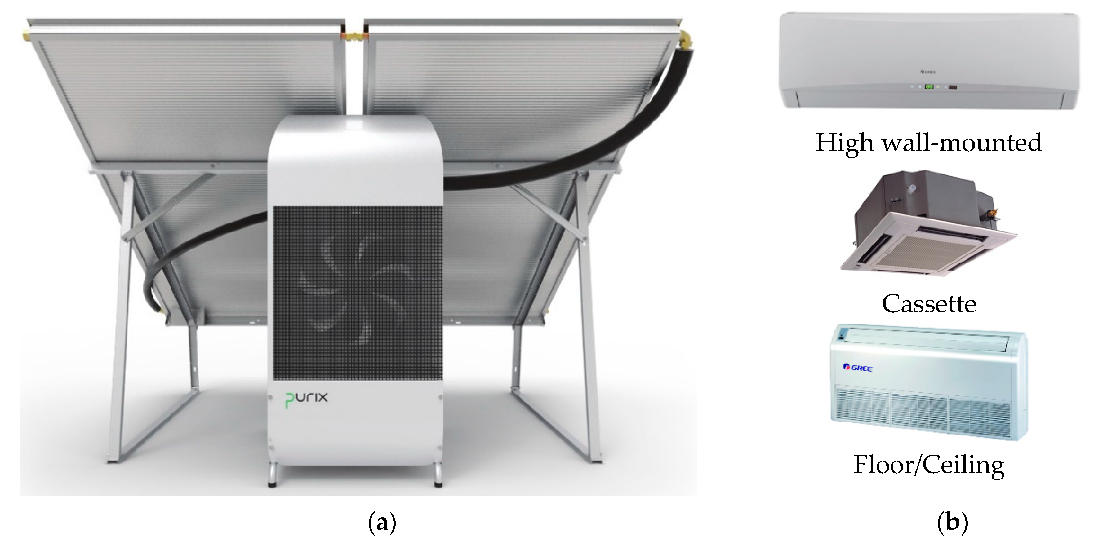
PURIX ApS
(Copenhagen, Denmark) [19,20,44]
Cycle type: Single-effect
Product: Type A25
2.5DHS inlet: > 70 d
Ambient: 35 e
CHW inlet/outlet: 18/13
0.81- Directly air-cooled absorber and condenser
- Complete set of solar air conditioner (A25s): outdoor unit (i.e., solar collectors and absorption chiller (ASC) and indoor unit (fan coils)
Thermax Ltd.
(Pune, India) [42]
Cycle type: Single/double-effect driven by heat sources at two temperature levels
Product: 2D Series (e.g., EJ Series)
175–12,300 aDHS inlet/outlet: N/R
HR inlet/outlet: N/R
CHW inlet/outlet: N/R
1.1–1.2- High-grade: steam (~3.9–9.8 bar); exhaust gas (350–600 °C); hot water (150–180 °C)
- Low-grade: hot water (80–95 °C) and steam ( 3.4 bar)
- Minimum CHW supply temperature: up to 1 °C (water) and up to −2 °C (brine)
World Energy Co., Ltd. (Gunpo-si, South Korea) [36,45]Cycle type: Single-effect double-lift
Product: Models 2ABH and 2AB
105–4571 aDHS inlet/outlet: 95/55
HR inlet/outlet: 31/36.5
CHW inlet/outlet: 13/8
0.73- DHS temperature glide (K): 40
W. Baelz & Sohn GmbH & Co. (Heilbronn, Germany) [26,28,46,47]Cycle type: Single-effect
Product: Baelz-absorpdynamic® Bee [26]; Bumblebee [27]; and Hornet [28]
Bee: 50
Bumblebee: 160
Hornet: 500
DHS inlet/outlet: 90/72
HR inlet/outlet: 30/(37 or 38) [46]
CHW inlet/outlet: 21/16
~0.8- Minimum DHS inlet temperature: 55 °C (“Bee”) and 60 °C (“Bumblebee” and “Hornet”)
- Minimum CHW supply temperature: 5 °C
- Quick response for cooling load changes: 25% to 100% in less than 10 min [47]
- DHS temperature glide (K): 18
- Maximum HR temperature: 55 °C (“Bee”); 40 °C (“Bumblebee” and “Hornet”)
a Includes large capacity; b For the European market; c For the Asian market (e.g., Japan); d Minimum driving hot water temperature; e Outdoor (ambient) temperature; CHW = chilled water; C O P t h = thermal COP; DHS = driving heat source; HR = heat rejection medium; N/R = not reported; PHE = plate heat exchanger.
Table 2. Research projects on small capacity laboratory and pre-industrial prototypes with special features suitable for solar space cooling applications.
Organization,
Project Partners
(Country)
TechnologyWorking
Fluid
Capacity (kW)Temperature (°C) C O P t h (-) RemarksAuthors (year),
References
Munich University of Applied Sciences
(Germany)
Cycle type: Compressor-boosted, single-effect
Components: Falling film over side-by-side horizontal tube bundles HX for thermal components (ABS, CON, DES, and EVA) and R718 turbo compressor
H2O/LiBr15DHS: 90 (inlet)
HR: 35–40 (CW inlet)
CHW: 6 (outlet)
0.753 *- Laboratory prototype
- turbo compressor: up to 3.5 pressure ratio; 90,000 rpm; and ~60% isentropic efficiency for <3.0 pressure ratio
Helm et al. (2019) [82]
Universidad Nacional Autónoma de México
(Mexico)
Cycle type: Single-effect
Components: (i) PHE with vertical orientation for the DES, EVA, and SHX; and (ii) serpentine finned stainless-steel tubes for the ABS and CON
NH3/LiNO30.8–3.4DHS: 80–100 (inlet)
HR: 20–32 (CW inlet)
CHW: <2.6
0.1–0.33 - Laboratory prototype
- Directly air-cooled chiller
- Alfa Laval™ model Alfanova 52 for the DES and SHX using 40 and 20 plates, respectively.
- Alfa Laval™ model Alfanova 27 using 20 plates for the EVA
Soto and Rivera
(2019) [64]
Universidad Nacional Autónoma de México
(Mexico)
Cycle type: Single-effect
Components: (i) PHE with vertical configuration for the ABS, CON, DES, EVA, and SHX; and (ii) stainless-steel finned tube for the REC
NH3/H2O 2.6 aDHS: 85–105 (inlet)HR: 20–32 (CW inlet)CHW: 20 (inlet); N/R (outlet) 0.61 a- Laboratory prototype
- −19 °C EVA temperature
- Alfa Laval™ model Alfanova 52 used for the ABS, DES and SHX using 40 plates
- Alfa Laval™ model Alfanova 27 used for the CON and EVA using 20 plates
Jiménez-García and Rivera
(2019) [49]
University of Innsbruck, Graz University of Technology,
Pink GmbH (Austria)
Cycle type: Single-effect and half-effect (double-lift)
Components: PHE used for the ABS, CON, DES, and EVA
NH3/H2O 18.4 b
10.6 c
DHS: 85 (inlet)
HR: 20 b (inlet); 20–35 b;
20–45 c (inlet)
CHW: 12/6 (inlet/outlet)
0.57 b
0.27 c
- Laboratory prototype
- Designed as a switchable system between single-effect and half-effect with a cooling capacity of 20 kW in single-effect
Neyer et al.
(2018, 2017)
[77,78]
Universidad Nacional Autónoma de México
(México)
Cycle type: Single-effect
Components: Stainless-steel PHE with vertical configuration for the ABS, CON, DES, EVA, and SHX
NH3/LiNO33.1 a
0.28–2.29 d
DHS: 80–95 (inlet)
HR: 20–32 (inlet)
CHW: 6 (outlet)
0.62 a
0.032–0.23 d
- Laboratory prototype
- Alfa Laval™ model Alfanova 52 used for the ABS, DES, and SHX using 40 plates
- Alfa Laval™ model Alfanova 27 used for the CON and EVA using 20 plates
Jiménez-García and Rivera (2018) [61]
Politecnico di Milano
(Italy)
Cycle type: Double-lift (half-effect)
Components: Vertical shell-and-tube falling-film HX as the DES; tube-in-tube horizontal flow for the SHXs and the RCA; a shell-and-tube vertical flow countercurrent HX as the EVA; steel tube coils with vertical aluminum fins as the ABS and CON; and pall ring packed bed with solution cooled coil as the REC
NH3/H2O2.5 **DHS: 80–90 (inlet)
CW: 22–38 (CW inlet)
CHW: 12/7
0.3 ** - Laboratory prototype
- Air-cooled chiller
- Electrical COP of 10 **
Aprile et al. (2015);
Guerra (2014)
[75,76]
Universitat Rovira i Virgili, CIAT
(Spain)
Cycle type: Single-effect
Components: Brazed PHEs for all the thermal components (ABS, CON, DES, EVA, and SHX)
NH3/LiNO3 12.9 e
9.3 f
DHS: 90 (inlet)
CW: 35 (CW inlet or ambient air)
CHW: 15 (outlet)
N/R- Two pre-industrial prototypes (indirectly air-cooled and water-cooled absorption chillers)
- Nominal design parameters: cooling capacity of 10 kW; chilled water outlet of 1 °C; hot water and cooling water inlet of 90 °C and 37.5 °C, respectively
- Electrical COP of 19.3 e and 6.5 f
Zamora et al. (2014) [57]
Universitat Politècnica de Catalunya,
Termo Fluids S. L.
(Spain)
Cycle type: Single-effect
Components: falling-film heat exchangers with improved designs for heat and mass transfer.
H2O/LiBr7DHS: 88 (inlet)
HR: 35 (air)
CHW: 9 (outlet)
0.7- A pre-industrial prototype
- Directly air cooled absorption chiller
Oliva et al. (2014),
Farnós et al. (2014) [69,84]
* ( t dhs , in / out = 89.9/66.3 °C, t chw , in / out = 12/6.3 °C and, t cw , in = 34.8 °C); ** at ambient temperature of 30 °C; a Based on internal variables; b Single-effect; c Half-effect; d Based on external variables; e Water-cooled; f Air-cooled. ABS = absorber; CHW = chilled water; CON = condenser; CW = cooling water; DES = desorber; DHS = driving heat source; EVA = evaporator; HR = heat rejection medium; HX = heat exchanger; N/R = not reported; PHE = plate heat exchanger; RCA = refrigerant cooled absorber; REC = rectifier; SHX = solution heat exchanger.

