Article

A Novel Experimental Study on the Effects of Soil and Faults’ Properties on Tunnels Induced by Normal and Reverse Faults

by
Mehdi Ghafari
,
Haslinda Nahazanan
*,
Zainuddin Md Yusoff
and
Nik Norsyahariati Nik Daud
Department of Civil Engineering, Faculty of Engineering, Universiti Putra Malaysia, Selangor 43400, Malaysia
*
Author to whom correspondence should be addressed.
Appl. Sci. 2020, 10(11), 3969; https://doi.org/10.3390/app10113969
Submission received: 5 April 2020 / Revised: 27 April 2020 / Accepted: 9 May 2020 / Published: 8 June 2020
(This article belongs to the Special Issue Spatial Modeling in Environmental Analysis and Civil Engineering)

Abstract

:
Due to the world population increasing considerably, there is a need for efficient public transportation, such as the subway. However, it has become a major concern to geotechnical engineers that the development and construction of subways are held underground where faults exist, as it will be a major risk to any structure if the fault is still active. Several seismic events, such as the earthquakes in Taiwan in 1999, China in 2008, and Malaysia (Sabah) in 2015, caused by fault ruptures, signify the importance of this study. In this paper, a physical model of 1000 mm in height, 3000 mm in length, and 1000 mm in width, which is the largest single gravity (1g) model for simulation faults (normal and reverse) ever built, was fabricated to evaluate the influence of various soil properties, various fault angles, and tunnel depths on tunnels affected by normal and reverse faults. The effects of various soil properties, such as water content, particle size, cohesion, and friction angle, had revealed major changes (approximately by 34%, 39%, 64%, and 39%, respectively) in tunnel displacements. Results also showed that increasing of fault angle could increase the tunnel displacement as much as two times. In addition, when a tunnel is located close to the ground surface, 22% less displacement was found to have occurred to the tunnel. With the results obtained from the physical model, simulation had been made using plane strain and axial symmetry (PLAXIS) software. The comparison made between rock and soft soil showed that soft soil imposed two times more displacements than rock, and an existence of foundation in soft soil and rock can decrease the tunnel displacements by 6% and 4%, respectively. This paper asserts that besides the structural design of a tunnel, the geotechnical design also has a major impact on the safety and robustness of the tunnel, in which aspects such as soil properties, tunnel depth, and fault angle have a strong influence on tunnel damages which were not considered in previous research, despite their importance.

1. Introduction

Fault ruptures are caused by sudden movement on a fault, when stress on the edge overcomes the friction, and energy in waves are released and travel through the soil. In recent years, there has been an increasing amount of research on this topic due to several major incidents, such as fault ruptures in Taiwan in 1999, Turkey in 1999, the USA in 2002, Japan in 2004, China in 2008, and in Iran in 1990 [1,2,3,4,5,6]. Furthermore, in 2015, an earthquake with a magnitude of 6 occurred in Sabah, Malaysia, which was recorded as the second largest earthquake in the country after the 1991 earthquake in Ranau, which was also in Sabah [7]. A tectonic map of fault activity revealed that Sabah’s fault was part of a 200 km-long system of normal faults that crosses the eastern side of the Crocker Range, parallel to Sabah’s northwest coastline [8].
Two types of physical models, namely, centrifuge and 1g models, have been used in previous studies on fault ruptures [9,10]. The centrifuge model has the ability to change the centrifuge’s acceleration, Ng, where N stands for the scaling factor and g stands for the acceleration of gravity. It means that a unit weight of soil in the centrifuge is N times the unit weight at 1g [11,12,13,14,15,16]. It involves changing gravity to simulate a real situation. However, fault simulations with centrifuge tests were mostly used to investigate free fields (fields without any structures) and cohesionless soil [13,15,17]. Several studies have examined the relationship between shear zone and damages, and the findings show that soil experiences the highest stress and strain in the shear zone, which causes damages to soil. Lee et al. used the centrifuge model for an experimental investigation to explore the shear zone when faults happen in a free field, and he showed that soil density can have a major influence on ground surface displacements [18]. The 1g model is more preferred to be used for simulating the effect of soil properties on tunnels induced by faults. Firstly, unlike the centrifuge model, which is very sensitive to achieve certain gravity, natural gravity is used in the 1g model. Secondly, the process of increasing the vertical component in the 1g model can be manipulated, and also, more gauges can be installed in the 1g model due to its larger size. Thirdly, the effects of various soil properties can be investigated more accurately as it involves greater mass of soil.
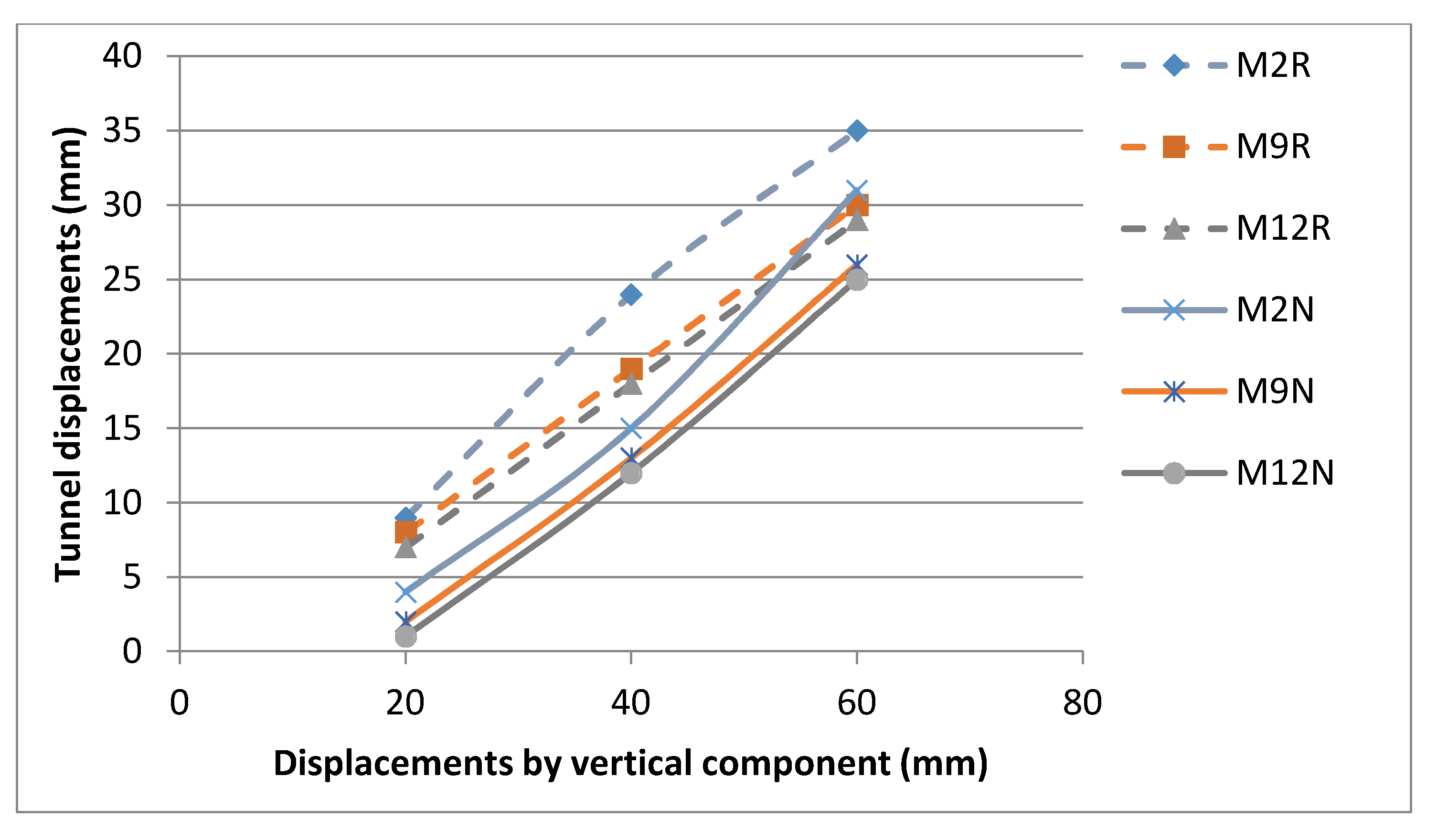
Investigation on the effects of soil properties alone shows that deformations of wet and dry soil when a fault happens are different. It was found that wet soil shows a major increase in piston pressure compared to dry soil, illustrating that wet soil increases the soil strength [19]. Soil density is another important aspect of soil failure. The shear zone in low-density soil is typically more complex than in high-density soil, and as the relative density of the ground model becomes more significant, the number of rupture planes decrease because soil strength does not allow more fractures in the soil [9,
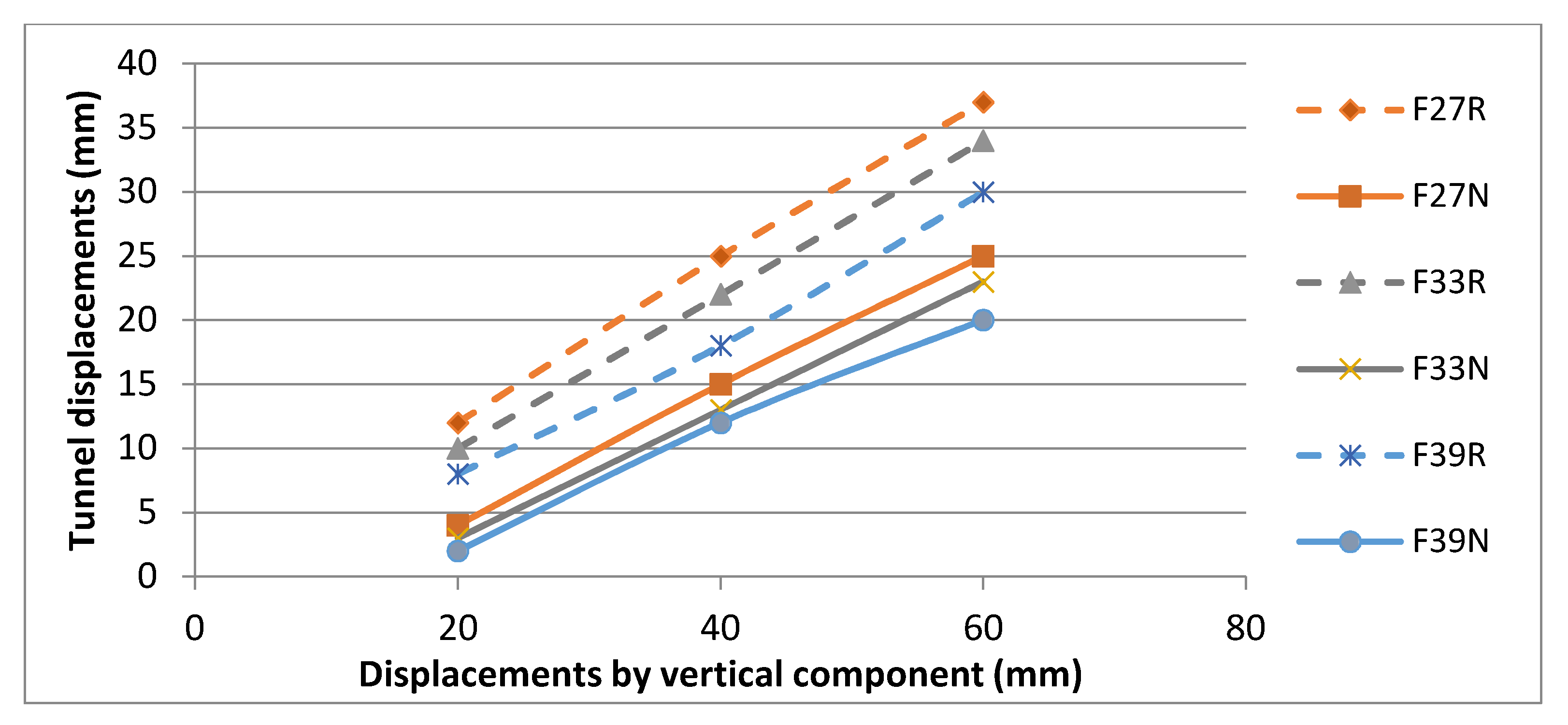
11]. Furthermore, soil properties such as cohesion, friction angle, particle size, density, and water contents are very important in any simulation and analysis involving soil [20,
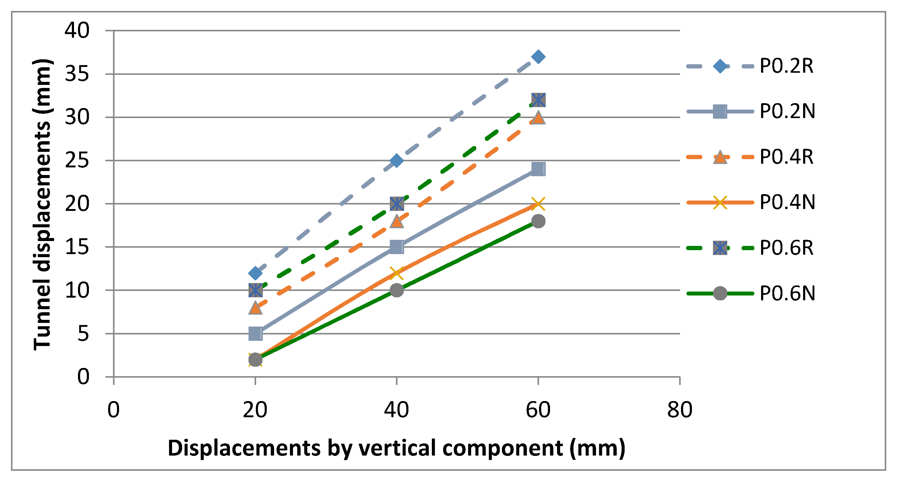
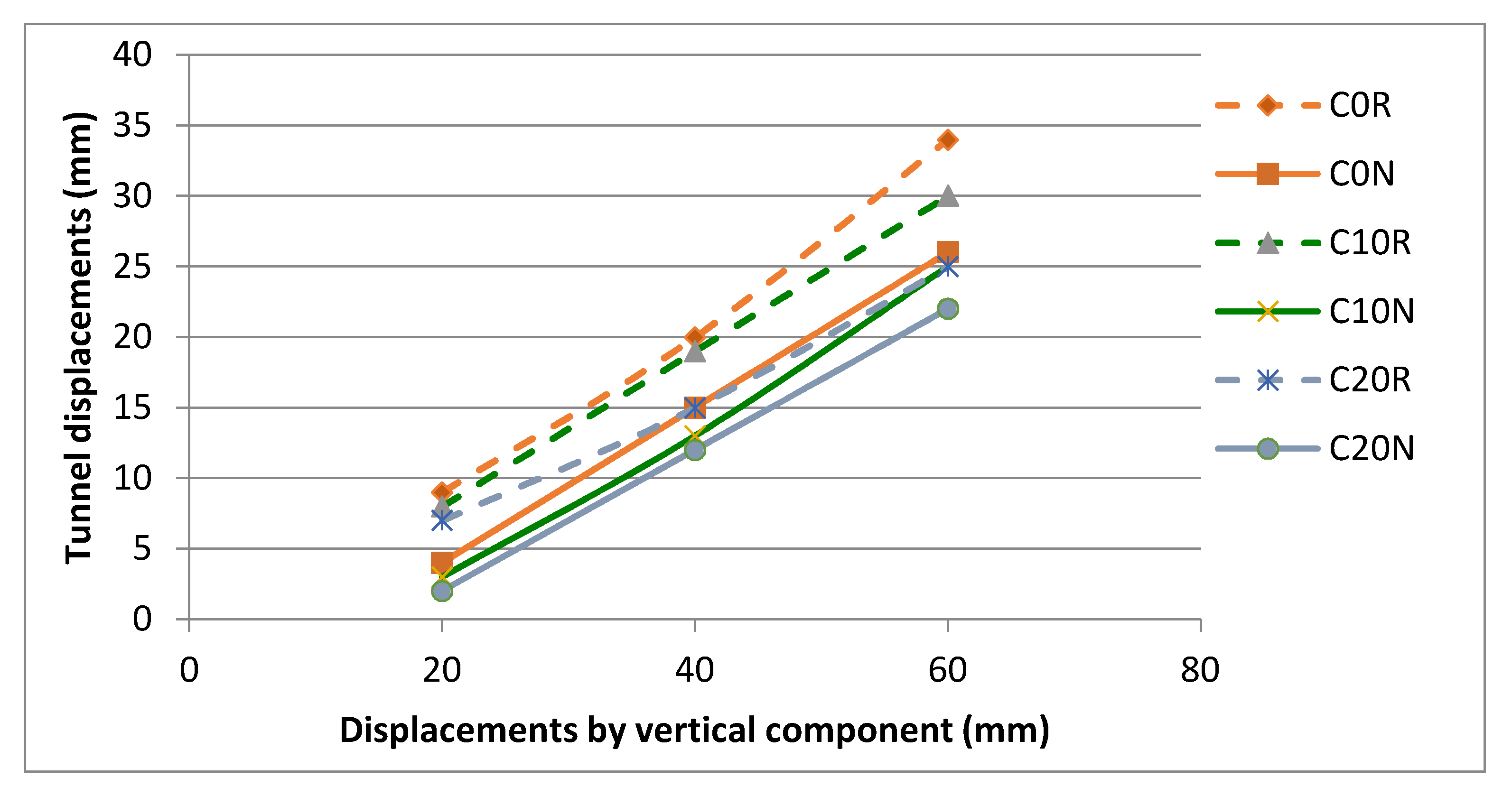
21]. Results from previous studies have shown that changing of soil friction angles and cohesion could affect the bearing capacity of soil [22,23]. The results from Khezri et al. showed that cohesion is very important to be measured in underground structures because cohesion increases with depth and each layer of soil has different cohesion [24]. Furthermore, soil particle size and water content have been claimed to have critical impacts in designing foundations, roads, and other infrastructure [25,
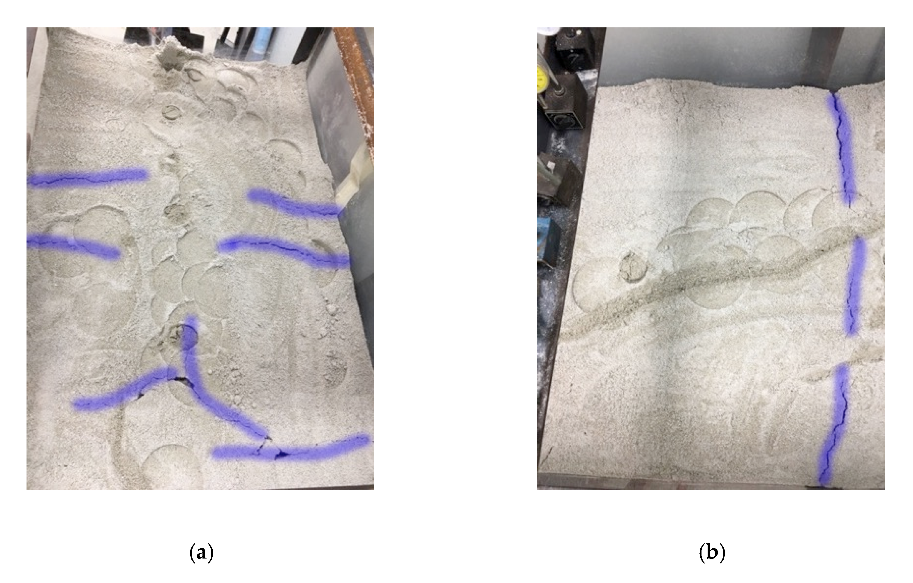
26]. Moreover, normal and reverse faults would also have different impacts on soil deformations. When a normal fault happens, at least one rupture propagation reaches the ground surface and damages building foundations, and there could be more impacts on the soil [10,27].
Tunnels and subways will be the first structures to experience damages when any movements happen, before the forces caused by faults reach the ground surface. Hence, the stability of tunnel structures should be given more consideration by engineers. Millions of people use underground public transportation every day, and hence, fault ruptures could pose a major hazard to their lives. Restoration of structures is another challenge because it can be very costly and is sometimes impossible. Thus, more research in this area is needed to reduce the damages to tunnels and buildings. Besides fault characteristics, soil properties also impose major influences and need particular attention. Several studies have previously been conducted in fault ruptures, in which none have considered soil properties as one of the major aspects of tunnel displacement. The simulation of normal and reverse faults can be shown by lifting the bottom of the physical model upward or downward, for simulating reverse and normal faults, respectively. Researchers have evaluated the limitations of displacements, and different data have been found, showing that h H % (h stands for movements of the hanging wall and H stands for the depth of the sand box) can produce the range of 4% to 10%. The displacement will cause some changes to ground surfaces, which are different based on soil properties [27,28,29]. In this study, the ranges were chosen between 2.7% to 8%. In previous studies, the effect of displacements was only measured on the ground surfaces; while in this study, the displacements also have been measured on an embedded tunnel.
In this paper, an experimental investigation was conducted to explore the effects of various soil properties, such as cohesion, water content, particle size, and friction angle, and various fault properties, such as fault types, angles, and tunnel depth, by using a 1g model. Furthermore, differences and similarities of normal and reverse faults, the effects of various fault angles, and tunnel depths on tunnels have also been investigated. Plane strain and axial symmetry (PLAXIS) software is a useful tool for analyzing two- and three-dimensional models, and has been used for different circumstances, such as modeling rock mass parameters, tunnels, foundations, and many more. In this paper, PLAXIS software was used for simulating the effect of faults on soft soil and rock, and also the influence of foundation on tunnel displacements. Furthermore, unlike other studies that only investigated free fields, this research focuses on a field with a tunnel. The outcome of this study is believed to help engineers in understanding the level of damage that might be imposed on tunnels at the area of a fault, with various properties of soil and faults.

2. Methodology

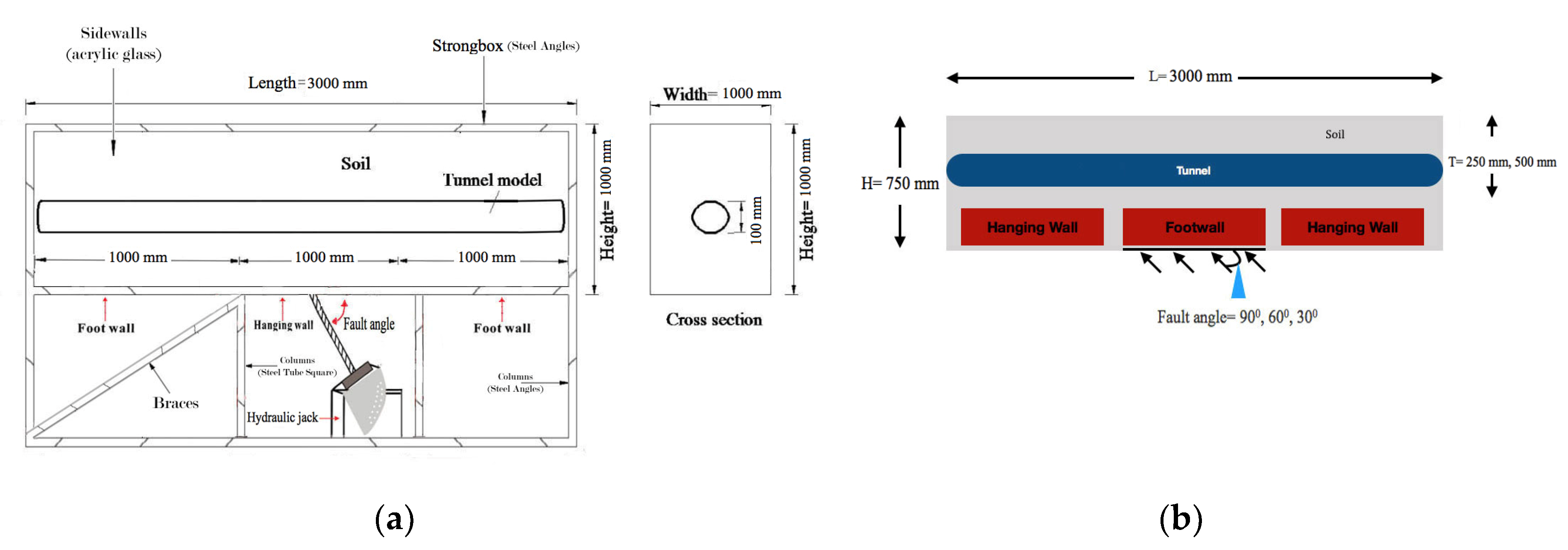
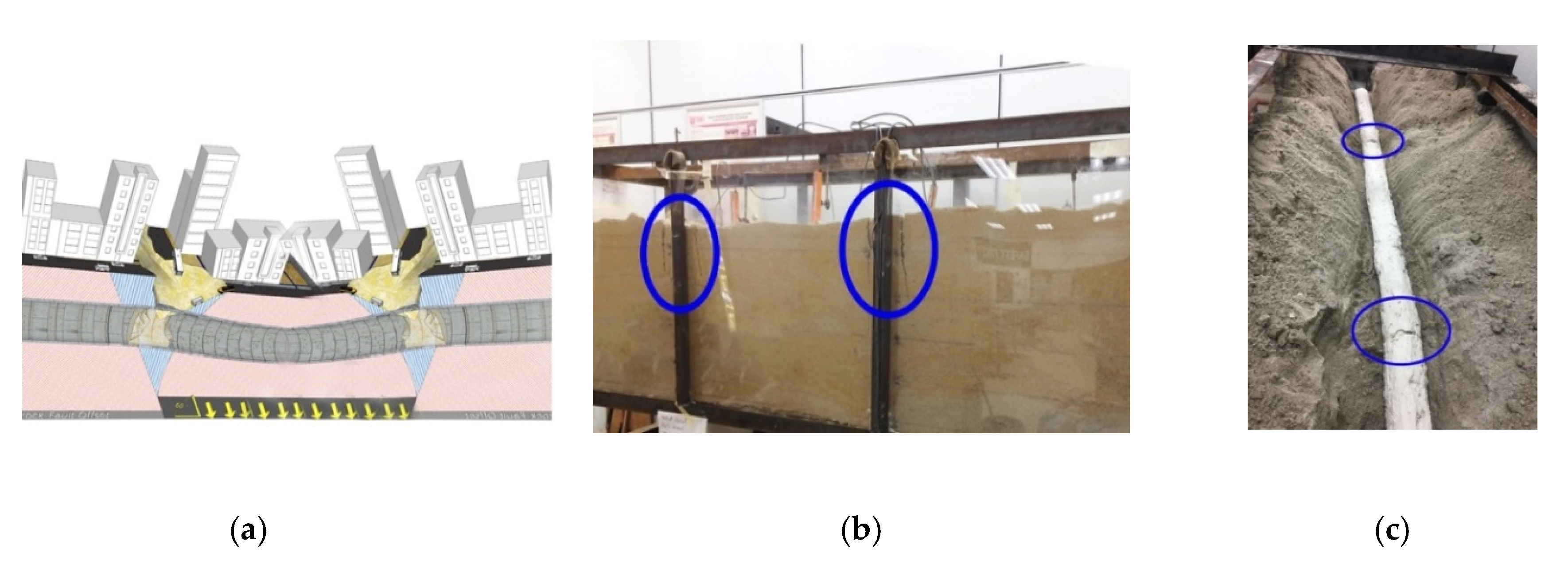
A physical model of 3000 mm length × 1000 mm width × 1000 mm height was fabricated in the Geomechanics laboratory, UPM, to simulate both types of normal and reverse faults, following the established boundary conditions of B = 4H, where H stands for thickness and B is the length of the physical model. The physical model consists of stable and movable parts, which can be moved upward and downward using a hydraulic jack to simulate reverse and normal faults respectively, see Figure 1.
Three different water contents, particle sizes, cohesions, and friction angles, were assessed to evaluate the effects of various soil properties on the tunnel when a fault happens (Table 1, Table 2, Table 3 and Table 4). The fault angle of 60° remained constant in all tests at various soil properties and the soil type based on unified soil classification system (USCS) is poorly graded sand (SP). The natural water content was determined to be 5% and specimens with 2% water content were prepared by letting them air-dry in the laboratory for two weeks. Specimens with 9% and 12% water content were prepared with different amounts of water, as shown in 
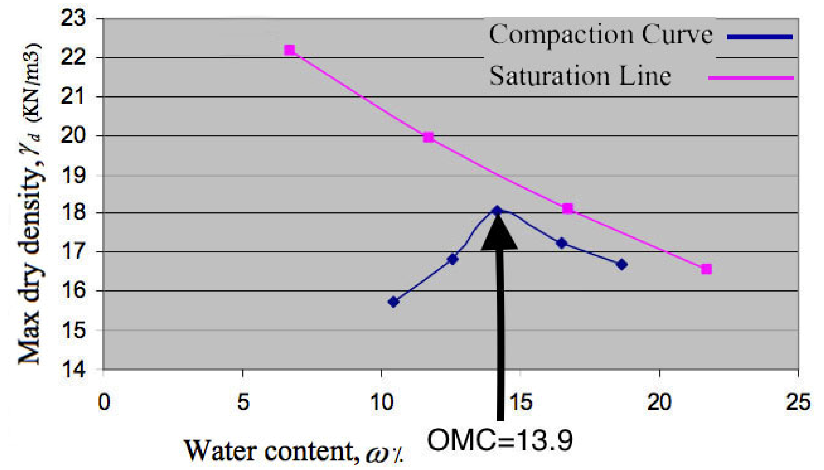
Table 5. To achieve a certain percentage of water content, after conducting several tests, the results showed that 95 kg of water could increase the soil water content of 3.7 tons of soil by approximately 3%. A compaction test was conducted to find the optimum water content (OMC), and the result obtained was an OMC of 13.9, as illustrated in Figure 2. The reason for choosing the maximum water content of 12% was to achieve a soil density of 80% and soil friction angle of 39°.
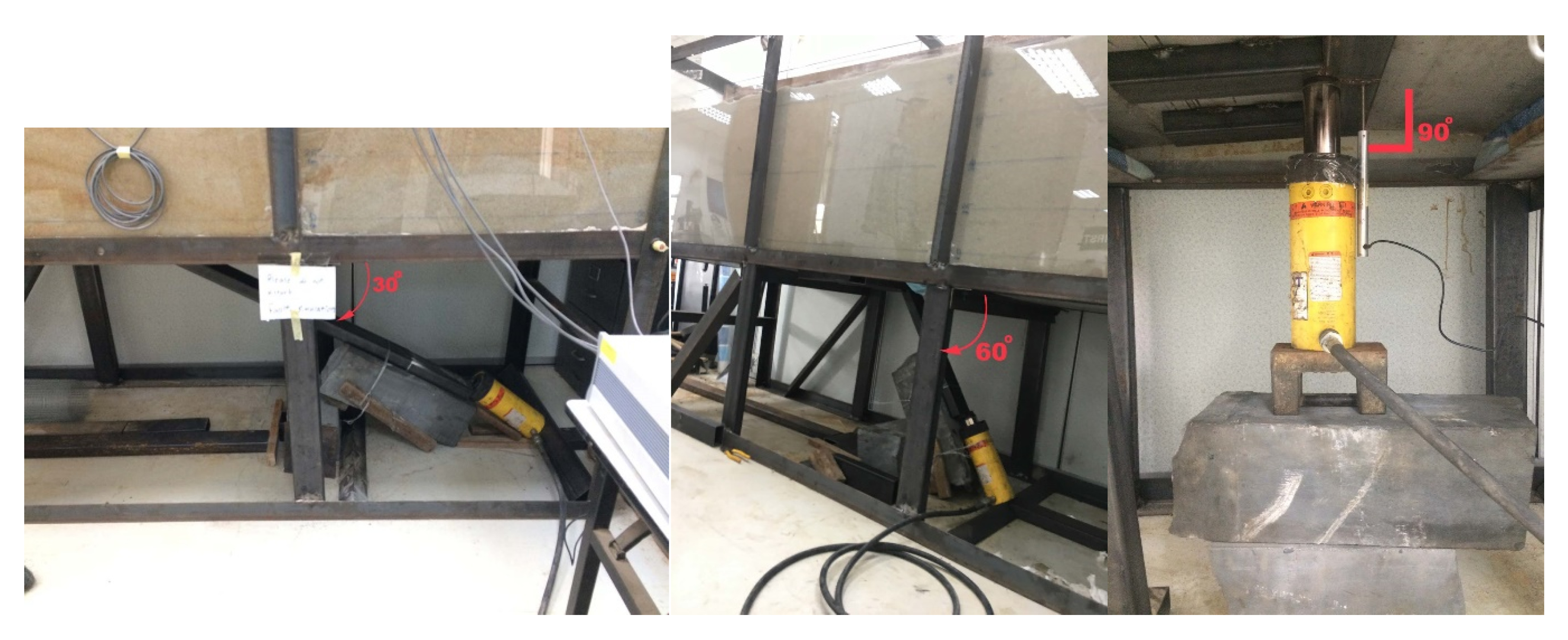
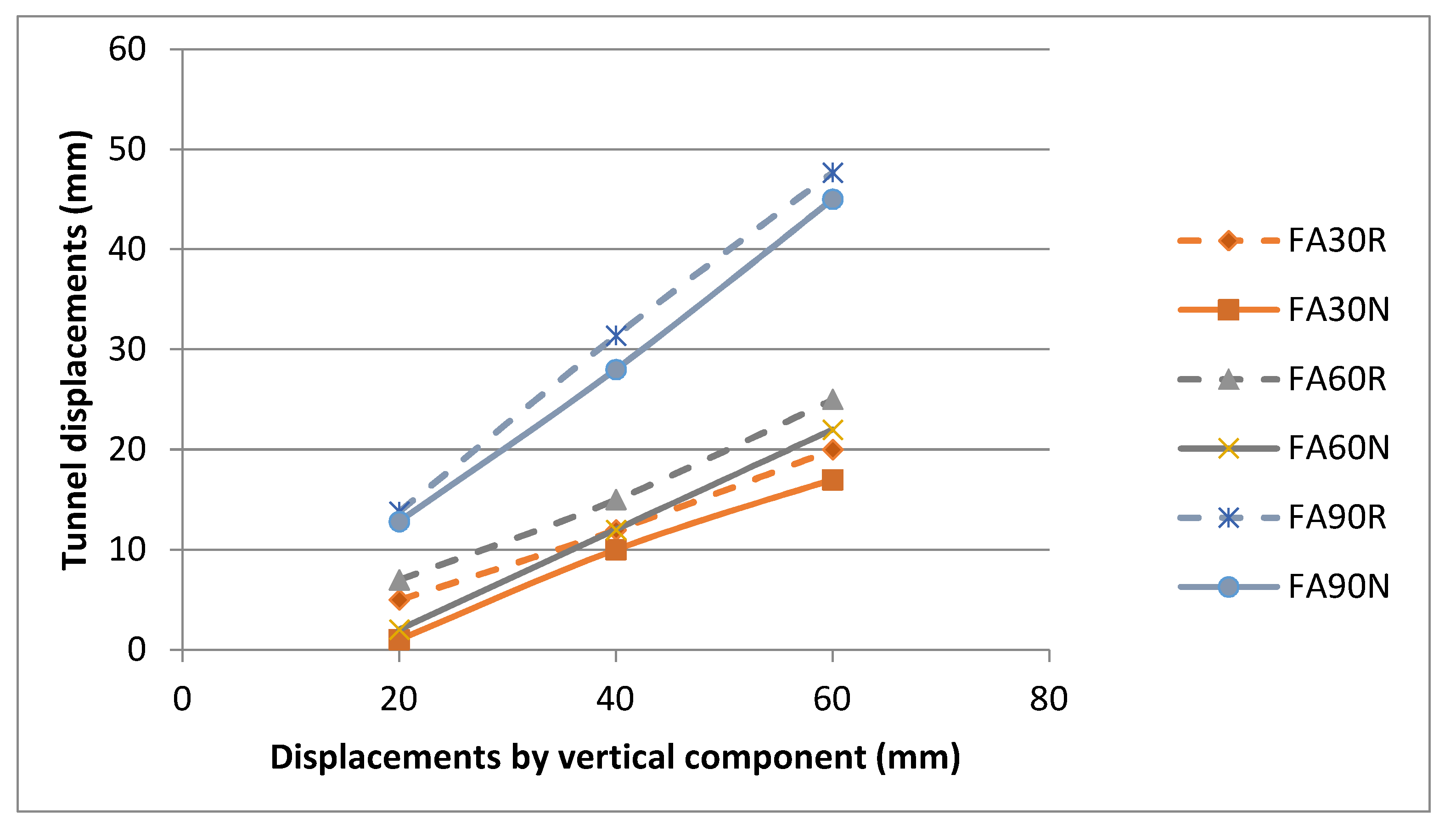
The effects of fault angles was studied at 30°, 60°, and 90°, see Table 6, and 
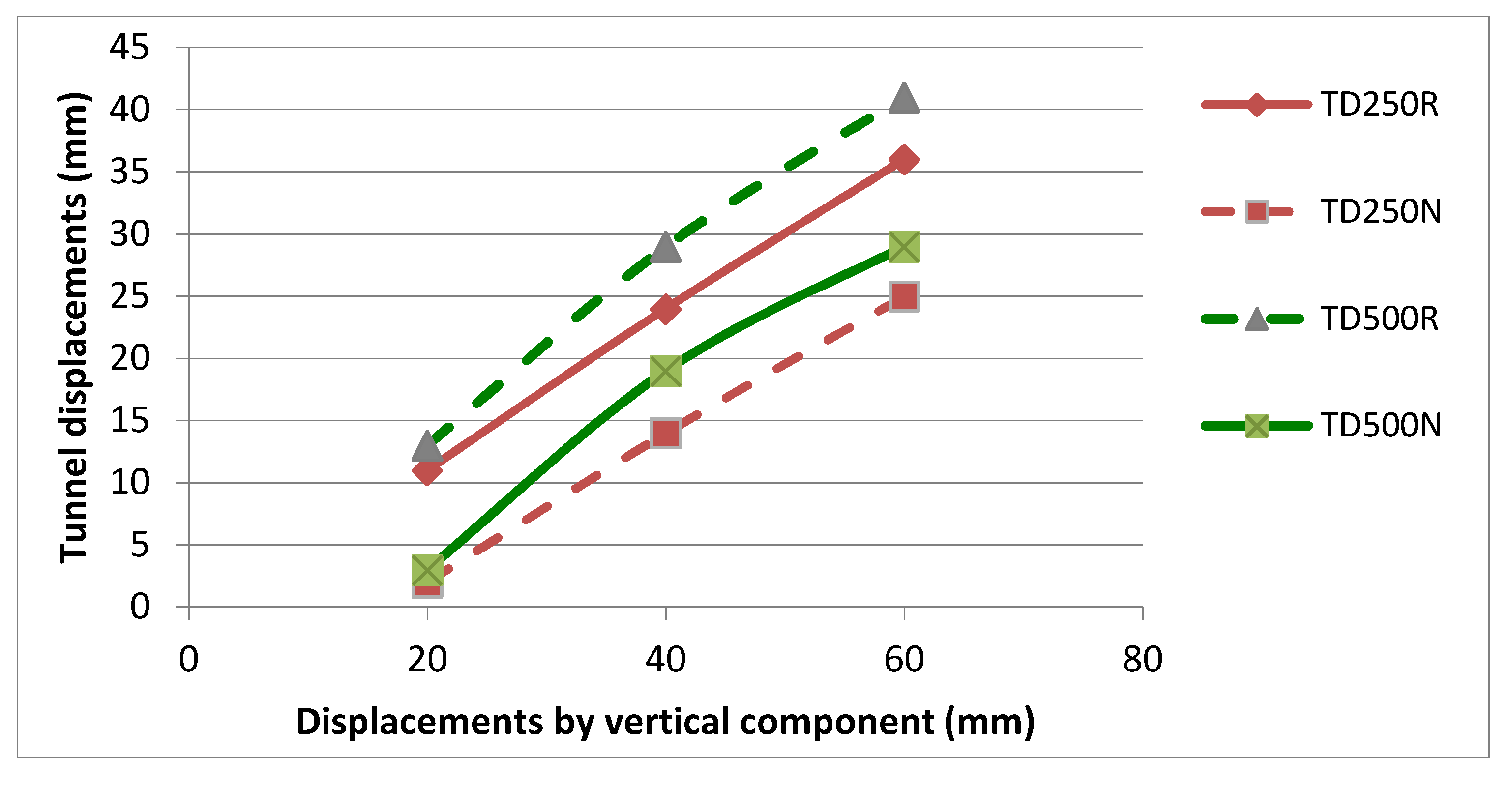
Figure 3 illustrates how they were employed in this study. Furthermore, the tunnel depths were chosen to be located at 250 and 500 mm from the surface, see Table 7. The values of soil properties for the soft soil and rock (in the United State Army Corps of Engineers, categorized as loose and dense sand) evaluated in PLAXIS have been collected from case studies, see Table 8 [23,
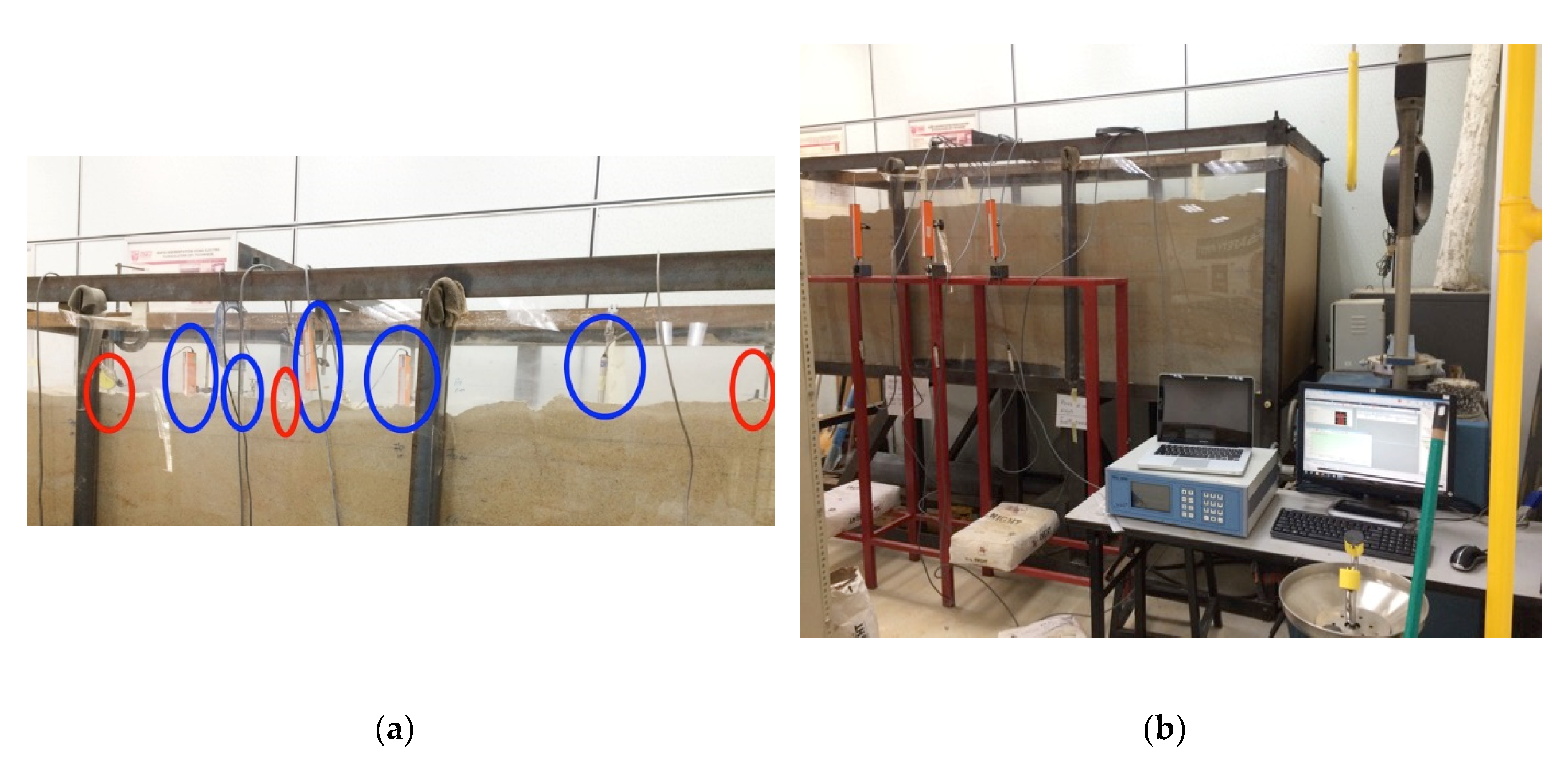
30]. The tunnel displacements were recorded by three strain gauges, and five linear variable differential transformer (LVDT) were used (Figure 4) on top of the physical model. The five LVDTs were installed to show the displacements of the tunnel, and the three strain gauges were installed to show the ground surface displacements. Most of the gauges were installed in the middle of the physical model because forces are located where the fault is located, and hence the displacements could be recorded at its maximum.

3. Results

3.1. Effects of Various Soil Properties on Displacements

3.1.1. Water Content

Figure 5 shows the effects of various water contents on tunnel displacements induced by both normal and reverse faults. Water contents of 2%, 9%, and 12% in reverse faults were labeled as M2R, M9R, and M12R, and in normal faults were labeled as M2N, M9N, and M12N. The results show that the tunnel, after a 15 mm displacement by the vertical component, had lost its strength, and tunnel displacement reached 31 mm, which is higher than in the reverse fault with a water content of 9% (M9R). Another important aspect is the major differences (almost 34%) between M2R and M12R, revealing how the existence of water in the field could reduce displacements and damages to tunnels. The same curves in the normal and reverse faults for M9N and M12N show that the percentages of water content at an optimum water content (OMC = 13.9%) exhibited less differences in tunnel displacements. The findings on normal and reverse faults revealed that displacements decline with increasing soil water content (before reaching the OMC level). This aspect can also be found in previous studies [31,32]. Another reason for the decreasing displacements was found by Kumari, which is that soil cohesion increases with the rise in water content, causing the shear forces to increase, thus giving the soil more strength [33].

3.1.2. Particle Size

Figure 6 illustrates the effects of various soil particle sizes on tunnel displacements induced by both normal and reverse faults. Soil particle sizes of 0.2, 0.4, and 0.6 mm were labeled as P0.2R, P0.4R, and P0.6R respectively, for reverse faults, and P0.2N, P0.4N, and P0.6N for normal faults. Overall, the curves of reverse faults are sharper than those in normal faults. The results revealed that soil particle size of 0.6 mm had less displacements than the others. For instance, the results showed an almost 39% difference in displacements between the finest (P0.2R) and the largest (P0.6R) soil particle size. The most relevant study from the literature is by Deepa, which revealed that coarse sand with clay has a higher soil strength and can tolerate more stress in soil [34]. Notably, normal faults with particle sizes of 0.4 (P0.4N) and 0.6 mm (P0.6N) started from the same displacements (6 mm), but in a reverse fault, they had different starting displacements (8 mm for P0.4R and 10 mm for P0.6R). The results agreed with those of other studies, which showed that fine soil has less tolerance under force [35,36].

3.1.3. Cohesion

Figure 7 illustrates the effects of various soil cohesion, which was recorded to have a major impact to tunnel displacements. Cohesionless soil, and soil with cohesion of 10 kPa and 20 kPa were labeled as C0R, C10R, and C20R in reverse faults, and C0N, C10N, and C20N in normal faults. One of the significant changes was the sharp increase in tunnel displacements (from 2 to 22 mm) in C10N, when the vertical component reached 60 mm.
The results showed that higher soil cohesion can dramatically decrease the tunnel displacements. For instance, 27% of increment was exhibited in tunnel displacements when cohesion changed from C20R to C10R. The results can be discussed in reference to previous studies that showed that a higher cohesion increases the shear strength and the stability of soil [37,38]. In cohesionless soil, the results showed that the soil became deformed very easily, even with small displacements. Furthermore, in any project, it is important to know that cohesion increases with depth, and each layer has a different cohesion level [24].

3.1.4. Friction Angles

Figure 8 illustrates the effect of various soil friction angles on tunnel displacements induced by both normal and reverse faults. Soil friction angles of 27°, 33°, and 39° were labeled as F27R, F33R, and F39R in reverse faults, and F27N, F33N, and F39N in normal faults. The results show that F27R had almost 39% more displacements compared to F39R, and more fractures appeared on the surface of F27R (Figure 9). Also, the reverse fault (F27R) caused 48% more tunnel displacements compared to the normal fault when the friction angle was set at 27° (F27N). Furthermore, the closeness of the curves in normal faults at the beginning was in contrast with the reverse faults.
The results from the physical model also revealed that when a fault occurs, soft soil in displacements, h H (h stands for displacement and H stands for soil thickness), of more than 4% gets compacted first and then displaced. Moreover, soft soil makes more fractures and affects more ground surfaces than dense soil. The results also showed that in F39R and F39N, soil reaches the ground surface more easily and makes more displacements compared to soft soil. The results discussed in this section agreed with the finding by Moss et al., which is that dense soil can tolerate more deformation than soft soil [39]. When the soil friction angle was fixed at 39° and the displacement of the vertical component was set at 60 mm, the results showed that normal faults caused the maximum displacements of 20 mm to the tunnel. The results showed the importance of soil friction angles and soil density, where changing either in normal or reverse faults has a high impact on tunnel displacements. The results can be explained by a laboratory test on soil stability, which showed that increasing the friction angle decreases the settlements and also increases the shear strength in soil [40,41].

3.2. Effects of Fault Angle on Displacement

Figure 10 shows the importance of fault angles on tunnel displacements. Fault angles of 30°, 60°, and 90° were named as FA30R, FA60R, and FA90R for reverse faults, and FA30N, FA60N, and FA90N for normal faults. The results showed major tunnel displacements between fault angles of 30°, 60°, and 90°. FA30R recorded 5 times bigger displacement than FA30N when the vertical component was changed to 20 mm.
The major recorded numbers can be seen in FA90R and FA90N, with approximately 13.8 mm and 12.8 mm, respectively. The numbers had changed dramatically in 40 mm of movement by the vertical component, and the results showed that the displacements caused by FA90R and FA90N were more than twice those caused by FA60R and FA90N. However, the results were not dramatic when comparing fault angles of 30° to 60° in reverse and normal faults. The domination of changes between a fault angle of 90° with those of 30° and 60° also remained steady in 60 mm of movement by the vertical component in reverse and normal faults. The results showed that when the fault angle was changed to vertical, the forces became sharper and the displacements by the vertical component affected the tunnel more. The difference between normal and reverse faults revealed that under a normal fault condition, the soil experienced sinking and the fractures on the ground surface were not as sharp as under a reverse fault condition. The reason for this is that normal faults caused sinkholes and deformations [16].

3.3. Effects of Tunnel Depth on Displacement

Figure 11 illustrates the importance of the fault properties considered, which are tunnel depth on tunnel displacements. Tunnel depths of 250 and 500 mm were labeled as TD250R and TD500R in reverse faults, and TD250N and TD500N in normal faults. The results revealed that the tunnel exhibited more displacements when it was located closer to the fault. The maximum displacements of the tunnel could be as low as 31 mm for a reverse fault and 22 mm for a normal fault, which was recorded for the tunnel depth of 250 mm.
The results showed that for a tunnel depth of 250 mm, a 20 mm displacement by the vertical component caused tunnel displacements of 11 mm at the fault angle of 60°. However, for a tunnel depth of 500 mm, the tunnel experienced slight displacement, which was 13 mm for the fault angles of 60°. Comparison between reverse and normal faults revealed the huge differences between them. For the tunnel depths of 500 and 250 mm, the differences recorded were about 41% and 44%, respectively. The schematic of the tunnel bending is illustrated in Figure 12, which shows how normal faults can affect the ground surface and the buildings above it.

3.4. Finite Element Analysis

The comparison between rock and soft soil under normal and reverse fault conditions showed that soft soil could cause two times more displacements than rock, and a comparison between normal and reverse faults showed that the displacements caused by reverse faults could be more than four times those caused by normal faults, see Figure 13. In addition, both soft soil and rock have been used in PLAXIS software for displacements comparisons when foundation is added to the field with a tunnel. The displacements changed when foundation was added to the field, compared to without foundation when all stresses focused on the tunnel itself. Hence, foundation reduced the settlements of the tunnel. Figure 14 shows the differences in the total displacements obtained from the analyses done for the cases of without and with foundation. The results revealed that the existence of foundation in soft soil caused a reduction of ground surface displacements by 23% and tunnel displacements by 6%, see Figure 15.
Ground surface and tunnel displacements reduced by 14% and 4% respectively, in rocks compared with in soft soil. Furthermore, the exact soil properties used in the physical model were also tested and the results revealed reductions in the ground surface displacements by 29% and tunnel displacements by 7%. The results are well matched with Razmkhah et al.’s work, which showed that tunnels could minimize the surface displacements [42]. Furthermore, tunnels play a very important role for ground surface displacements and also reduce the displacements in foundation.

4. Conclusions

This study has shown that soil and fault properties have a major impact on tunnel displacements. Four important soil properties were focused on: water content, soil particle size, soil cohesion, and soil friction angle, which have been proven in this study to have major effects on tunnels. Fault angle and tunnel depth also showed influences on tunnel displacements.
  • The results showed that the major difference in displacements (almost 34%) was between the water contents of 2% and 12%. An increase in soil water content causes less displacements in wet soil compared to dry soil because there is more shear stress in wet soil.
  • Results also showed a significant effect of soil particle size on displacements. It was indicated that fine soil has less strength in faulting and has a major impact on tunnels. For instance, at the fault angle of 60°, the curves showed an almost 39% difference between the finest (0.2 mm) and the largest (0.6 mm) soil particle size. Furthermore, the findings of Hong et al. showed that fine soil has less strength in sudden movements, and faults are one of the sudden movements that happen in a short period of time [43].
  • The results on cohesionless soil at the angle of 60° under a reverse fault condition showed that cohesionless soil deformed very easily when the vertical component changed by more than 10 mm. Even with the increasing soil density, fractures appeared due to no cohesion in the soil. Hence, sand is very sensitive to displacements, and tunnels become deformed very easily. For instance, the results showed that when soil cohesion was changed from 20 kPa to cohesionless soil at a fault angle of 30° for a reverse fault, displacements increased by 64%. Moreover, higher cohesion increased the shear strength and the stability of the soil, leading to less displacement in soil.
  • It was also shown that friction angles play a crucial role in tunnel displacement. Increasing the friction angle decreased the settlements and also increased the shear strength in soil. The results showed that dense soil transfers more forces compared to soft soil. Also, the density of the soil helped to protect the tunnels from damages. On the contrary, in soft soil, all the forces were focused on the tunnels. Hence, displacements were more likely to be sharper.
  • Fault angles were also proven to play an important role in tunnel damages, and the current findings added to our understanding of fault angles and showed how they could have a major impact on tunnels. According to the results, the major changes were reported when the three fault angles of 30°, 60°, and 90° were tested. Sharp changes such as those at the fault angle of 90° caused more damages on tunnels because the forces were focused directly to the tunnels. However, at the fault angle of 30°, the damages to tunnels could be less and the tunnel could have less damages from the displacements because the distribution of forces on the tunnels does not focus on any specific point (unlike at the fault angle of 90°). The existence of tunnels has a major impact on the direction of the forces caused by fault angles. Tunnels change the direction of forces to vertical and more energy is pointed toward the middle part of the tunnels. However, when the fault angle is 30°, more tunnel parts are involved in tolerating the forces and the results showed 25% and two times less displacement compared to at the fault angles of 60° and 90°.
  • It was also shown that the displacements of the tunnel are different when the tunnel is located at a different depth. The findings can be concluded in three steps when a tunnel is added in a different depth. First, when the tunnel was located in 250 mm from the ground surface, the tunnel tolerated more forces induced by faults because soil absorbed some displacements and protected the tunnel from severe damages. Hence, the tunnel displacements decreased. Second, at a tunnel depth of either 250 or 500 mm, the fractures appeared after the vertical component moved approximately 20 mm, because the tunnel dramatically increased the bearing capacity of the soil. Third, as the tunnel was located closer to the fault (500 mm from the ground surface), more damages were likely to happen to the tunnel because more forces focused on the tunnel, compared to at 250 mm, where soil tolerated some displacements.
  • A comparison of the results between the physical model and the software showed the conformity of the data. Also, a simulation was carried out evaluating the differences between rock and soft soil, and the results revealed that soft soil could induce two times more displacements than the rock. Moreover, results from the field with a tunnel and foundation showed that soft soil could experience eight times more displacements than the rock, and tunnels could reduce displacements of foundations by approximately 34% in reverse faults and almost 24% in normal faults.

Author Contributions

M.G. designed and performed experiments, analysed data and wrote the paper. H.N. supervised the research and drafted and provided critical revision of the article. Z.M.Y. and N.N.N.D. provided final approval of the version to publish. All authors have read and agreed to the published version of the manuscript.

Funding

The research was funded by the Putra IPS Grant, GP IPS/2016/9505400, provided by Universiti Putra Malaysia.

Conflicts of Interest

The authors declare no conflict of interest.

References

  1. Bakir, P.G.; De Roeck, G.; Degrande, G.; Wong, K.K.F. Site dependent response spectra and analysis of the characteristics of the strong ground motion due to the 1999 Duzce earthquake in Turkey. Eng. Struct. 2007, 29, 1939–1956. [Google Scholar] [CrossRef]
  2. Faccioli, E.; Anastasopoulos, I.; Gazetas, G.; Callerio, A.; Paolucci, R. Fault rupture-foundation interaction: Selected case histories. Bull. Earthq. Eng. 2008, 6, 557–583. [Google Scholar] [CrossRef]
  3. Gazetas, G.; Pecker, A.; Faccioli, E.; Paolucci, R.; Anastasopoulos, I. Preliminary design recommendations for dip-slip fault-foundation interaction. Bull. Earthq. Eng. 2008, 6, 677–687. [Google Scholar] [CrossRef]
  4. Nováková, L. Evolution of paleostress fields and brittle deformation in Hronov-Poříčí Fault Zone, Bohemian Massif. Studia Geophys. Et Geod. 2014, 58, 269–288. [Google Scholar] [CrossRef]
  5. Alexandr, G. the Impact of Earthquakes of Tunnel Linings: A Case Study From the Hanoi Metro System. Int. J. Geomate 2018, 14, 151–158. [Google Scholar] [CrossRef]
  6. Ahmadi, M.; Moosavi, M.; Jafari, M.K. Experimental investigation of reverse fault rupture propagation through wet granular soil. Eng. Geol. 2018, 239, 229–240. [Google Scholar] [CrossRef]
  7. Yusoff, H.H.M.; Razak, K.A.; Yuen, F.; Harun, A.; Talib, J.; Mohamad, Z.; Ramli, Z.; Razab, R.A. Mapping of post-event earthquake induced landslides in Sg. Mesilou using LiDAR. Iop Conf. Ser. Earth Environ. Sci. 2016, 37, 012068. [Google Scholar] [CrossRef] [Green Version]
  8. Wang, Y.; Wei, S.; Wang, X.; Lindsey, E.O.; Tongkul, F.; Tapponnier, P.; Bradley, K.; Chan, C.-H.; Hill, E.M.; Sieh, K. The 2015 M w 6.0 Mt. Kinabalu earthquake: An infrequent fault rupture within the Crocker fault system of East Malaysia. Geosci. Lett. 2017, 4, 6. [Google Scholar] [CrossRef] [Green Version]
  9. Baziar, M.H.; Nabizadeh, A.; Jung Lee, C.; Yi Hung, W. Centrifuge modeling of interaction between reverse faulting and tunnel. Soil Dyn. Earthq. Eng. 2014, 65, 151–164. [Google Scholar] [CrossRef]
  10. Liu, X.; Li, X.; Sang, Y.; Lin, L. Experimental study on normal fault rupture propagation in loose strata and its impact on mountain tunnels. Tunn. Undergr. Space Technol. 2015, 49, 417–425. [Google Scholar] [CrossRef]
  11. Burridge, P.B.; Scott, R.F.; Hall, J.F. Centrifuge Study of Faulting Effects on Tunnel. J. Geotech. Eng. 1989, 115, 949–967. [Google Scholar] [CrossRef]
  12. Tongkul, F. The geology of Northern Sabah, Malaysia: Its relationship to the opening of the South China Sea Basin. Tectonophysics 1994, 235, 131–147. [Google Scholar] [CrossRef]
  13. Ahmed, W.; Bransby, M.F. Interaction of Shallow Foundations with Reverse Faults. J. Geotech. Geoenvironmental Eng. 2009, 135, 914. [Google Scholar] [CrossRef]
  14. Cai, Q.P.; Hu, P.; Laak, P.; Van Ng, C.W.W.; Chiu, A.C.F. Investigation of boundary conditions for simulating normal fault propagation in centrifuge. 4th Int. Conf. Geotech. Eng. Soil Mech. 2010, 614, 1–8. [Google Scholar]
  15. Chang, Y.Y.; Lee, C.J.; Huang, W.C.; Hung, W.Y.; Huang, W.J.; Lin, M.L.; Chen, Y.H. Evolution of the surface deformation profile and subsurface distortion zone during reverse faulting through overburden sand. Eng. Geol. 2015, 184, 52–70. [Google Scholar] [CrossRef]
  16. Kiani, M.; Akhlaghi, T.; Ghalandarzadeh, A. Experimental modeling of segmental shallow tunnels in alluvial affected by normal faults. Tunn. Undergr. Space Technol. 2016, 51, 108–119. [Google Scholar] [CrossRef]
  17. Ng, C.W.W.; Asce, F.; Cai, Q.P.; Hu, P. Centrifuge and Numerical Modeling of Normal Fault-Rupture Propagation in Clay with and without a Preexisting Fracture. J. Geotech. Geoenvironmental Eng. 2012, 1492–1502. [Google Scholar] [CrossRef]
  18. Lee, J.W.; Tabuchi, G.; Hamada, M. Experimental Approach for Understanding of Fault Rupture Propagation Through an Alluvial Soil. J. Earthq. Eng. Exp. 2003, 27, 1–4. [Google Scholar]
  19. Johansson, J.; Konagai, K. Fault induced permanent ground deformations—An experimental comparison of wet and dry soil and implications for buried structures. Soil Dyn. Earthq. Eng. 2006, 26, 45–53. [Google Scholar] [CrossRef]
  20. Lin, M.L.; Chung, C.F.; Jeng, F.S.; Yao, T.C. The deformation of overburden soil induced by thrust faulting and its impact on underground tunnels. Eng. Geol. 2007, 92, 110–132. [Google Scholar] [CrossRef]
  21. Ertugrul, N. Analysis of Seismic Behavior of Underground Structures: A Case Study on Bolu Tunnels. Master’s Thesis, The Graduate School of Natural and Applied Sciences, Ankara, Turkey, 2010. [Google Scholar] [CrossRef] [Green Version]
  22. Yang, H. Soil Slope Stability Investigation and Analysis in Iowa; Lowa State University: Ames, IA, USA, 2005. [Google Scholar]
  23. Zou, J.; Chen, G.; Qian, Z. Tunnel face stability in cohesion-frictional soils considering the soil arching effect by improved failure models. Comput. Geotech. 2019, 106, 1–17. [Google Scholar] [CrossRef]
  24. Khezri, N.; Mohamad, H.; HajiHassani, M.; Fatahi, B. The stability of shallow circular tunnels in soil considering variations in cohesion with depth. Tunn. Undergr. Space Technol. 2015, 49, 230–240. [Google Scholar] [CrossRef]
  25. Sudarsan, B.; Ji, W.; Adamchuk, V.; Biswas, A. Characterizing soil particle sizes using wavelet analysis of microscope images. Comput. Electron. Agric. 2018, 148, 217–225. [Google Scholar] [CrossRef]
  26. Pöhlitz, J.; Rücknagel, J.; Schlüter, S.; Vogel, H.J.; Christen, O. Computed tomography as an extension of classical methods in the analysis of soil compaction, exemplified on samples from two tillage treatments and at two moisture tensions. Geoderma 2019, 346, 52–62. [Google Scholar] [CrossRef]
  27. Anastasopoulos, I.; Gazetas, G.; Asce, M.; Bransby, M.F.; Davies, M.C.R.; El Nahas, A. Fault Rupture Propagation through Sand: Finite-Element Analysis and Validation through Centrifuge Experiments. J. Geotech. Geoenvironmental Eng. 2007, 133, 943–958. [Google Scholar] [CrossRef]
  28. Cole, D.A.; Lade, P.V. Influence Zones in Alluvium Over Dip-Slip Faults. J. Geotech. Eng. 1984, 110, 599–615. [Google Scholar] [CrossRef]
  29. Taniyama, H.; Watanabe, H. Deformation of Sandy Deposit by Reverse Faulting. Doboku Gakkai Ronbunshu 2001, 591, 135–142. [Google Scholar] [CrossRef]
  30. Corigliano, M.; Scandella, L.; Lai, C.G.; Paolucci, R. Seismic analysis of deep tunnels in near fault conditions: A case study in Southern Italy. Bull. Earthq. Eng. 2011, 9, 975–995. [Google Scholar] [CrossRef]
  31. García, A.J.H.; Jaime, Y.N.M.; Contreras, Á.M.Z.; Bastardo, L.D.S.; Llovera, F.A.S. Savanna soil water content effect on its shear strength-compaction relationship. Revista Científica UDO Agrícola 2012, 12, 324–337. [Google Scholar]
  32. Rahmat, M.N.; Ismail, N. Effect of optimum compaction moisture content formulations on the strength and durability of sustainable stabilised materials. Appl. Clay Sci. 2018, 157, 257–266. [Google Scholar] [CrossRef]
  33. Kumari, D. A study on the effect of moisture on strength characteristics of river sand, 2008–2009. Bachlor’s Thesis, National Institute of Technology, Rourkela, India, 2009. [Google Scholar]
  34. Deepa, P. Effect of Grading and Proportioning of Sand on the Compaction Properties and Shear Strength of Sand-Clay Mixtures; Report Project; University of Bangalore: Bengaluru, Karnataka, India, 2012. [Google Scholar]
  35. Liang, R.; Bai, X.; Wang, J. Effect of Clay Particle Content on Liquefaction of Soil. In Proceedings of the 12th World Conference on Earthquake Engineering, Auckland, New Zealand, 30 January–4 February 2000; pp. 1560–1564. [Google Scholar]
  36. Vangla, P.; Latha, G.M. Influence of Particle Size on the Friction and Interfacial Shear Strength of Sands of Similar Morphology. Int. J. Geosynth. Ground Eng. 2015, 1, 6. [Google Scholar] [CrossRef] [Green Version]
  37. Yokoi, H. Relationship between soil cohesion and shear strength. Soil Sci. Plant Nutr. 1968, 14, 89–93. [Google Scholar] [CrossRef]
  38. Kemper, W.D.; Rosenau, R.C.; Dexter, A.R. Cohesion Development in Disrupted Soils as Affected by Clay and Organic Matter Content and Temperature1. Soil Sci. Soc. Am. J. 1987, 51, 860. [Google Scholar] [CrossRef] [Green Version]
  39. Moss, R.E.S.; Stanton, K.V.; Buelna, M.I. The Impact of Material Stiffness on the Likelihood of Fault Rupture Propagating to the Ground Surface. Seismol. Res. Lett. 2013, 84, 485–488. [Google Scholar] [CrossRef]
  40. Mohammed, S.M. The Effect of Granular Material on Behaviour of Stone Columns in Soft Clay Under Embankment. Eng. Technol. J. 2015, 33, 2212–2219. [Google Scholar]
  41. Alshameri, B.; Bakar, I.; Madun, A.; Abdeldjouad, L.; Dahlan, S.H. Effect of Coarse Materials Percentage in the Shear Strength. IOP Conf. Ser. Mater. Sci. Eng. 2016, 136. [Google Scholar] [CrossRef] [Green Version]
  42. Razmkhah, A.; Pourlak, M.; Ghobakhloo, E. Seismic Waves Scattering Impact through Tunnel Excavation on Adjacent Monuments Subjected to Far Field Earthquakes. Civ. Eng. Dimens. 2014, 17, 18–24. [Google Scholar] [CrossRef] [Green Version]
  43. Hong-kai, C.; Xiu-zhu, Z.; Xiao-ying, H. Experimental Study on Settlement Characteristics of Grading Particles in Debris Flow Slurry. IERI Procedia 2013, 5, 265–270. [Google Scholar] [CrossRef] [Green Version]
Figure 1. Schematic of (a) physical model (b) strongbox.
Applsci 10 03969 g001
Figure 2. Graph from compaction test. OMC, optimum water content.
Applsci 10 03969 g002
Figure 3. Illustration of fault angles of 30°, 60°, and 90°.
Applsci 10 03969 g003
Figure 4. Illustration of (a) strain gauges (red circles) and linear variable differential transformer (LVDT) (blue circles), and (b) computer and data logger.
Applsci 10 03969 g004
Figure 5. The effect of water content in reverse and normal faults.
Applsci 10 03969 g005
Figure 6. The effect of particle size (D50) in reverse and normal faults.
Applsci 10 03969 g006
Figure 7. The effect of cohesion in reverse and normal faults.
Applsci 10 03969 g007
Figure 8. The effect of friction angle on reverse and normal faults.
Applsci 10 03969 g008
Figure 9. Fractures in (a) F27R (b) F39R.
Applsci 10 03969 g009
Figure 10. Fault angles of 30°, 60°, and 90° in normal and reverse faults.
Applsci 10 03969 g010
Figure 11. The effect of tunnel depth in normal and reverse faults.
Applsci 10 03969 g011
Figure 12. Failure when normal fault happens: (a) schematic diagram, (b) displacements, and (c) tunnel failure.
Applsci 10 03969 g012
Figure 13. Comparison between rock and soft soil in a field affected by normal and reverse faults.
Applsci 10 03969 g013
Figure 14. The total displacements shading, (a) without foundation and (b) with foundation.
Applsci 10 03969 g014
Figure 15. Soft soil ground surface displacements, (a) with foundation and (b) without foundation.
Applsci 10 03969 g015
Table 1. Soil properties used for various water content.
Soil Particle Size D50 (mm)Cohesion c (kPa)Soil Friction Angle ϕ (°)Fault Angle (°)Tunnel Depth (mm)Fault TypeWater Content w (%)Test Number
0.4103960250Reverse2M2R
Normal2M2N
Reverse9M9R
Normal9M9N
Reverse12M12R
Normal12M12N
Table 2. Soil properties used for various soil particle size.
Cohesion (c) (kPa)Soil Friction Angle ϕ (°)Water Content w (%)Fault Angle (°)Tunnel Depth (mm)Fault TypeSoil Particle Size D50 (mm)Test Number
10391260250Reverse0.2P0.2R
Normal0.2P0.2N
Reverse0.4P0.4R
Normal0.4P0.4N
Reverse0.6P0.6R
Normal0.6P0.6N
Table 3. Soil properties used for various soil cohesion.
Soil Friction Angle ϕ (°)Soil Particle Size D50 (mm)Water Content w (%)Fault Angle (°)Tunnel Depth (mm)Fault TypeCohesion c (kPa)Test Number
390.41230250Reverse0C0R
Normal0C0N
Reverse10C10R
Normal10C10N
Reverse20C20R
Normal20C20N
Table 4. Soil properties used for various soil friction angle.
Cohesion c (kPa)Soil Particle Size D50 (mm)Water Content w (%)Fault Angle (°)Tunnel Depth (mm)Fault TypeSoil Friction Angle ϕ (°)Test Number
100.41260250Reverse27F27R
Normal27F27N
Reverse33F33R
Normal33F33N
Reverse39F39R
Normal39F39R
Table 5. Amount of water content.
Water Content (%)Water (kg)
2Air dry
9190
12285
Table 6. Soil properties used for fault angles.
Cohesion c (kPa)Soil Friction Angle ϕ (°)Soil Particle Size D50 (mm)Water Content w (%)Tunnel Depth (mm)Fault TypeFault Angle (°)Test Number
20390.412250Reverse30C20R30
Reverse60C20R60
Reverse90FA90R
Normal30C20N30
Normal60C20N60
Normal90FA90N
Table 7. Soil properties used for various tunnel depths.
Cohesion c (kPa)Soil Friction Angle ϕ (°)Soil Particle Size D50 (mm)Water Content w (%)Fault Angle (°)Fault TypeTunnel Depth (mm)Test Number
0390.2260Reverse250TD250R
Reverse500TD500N
Normal250TD250N
Normal500TD500R
Table 8. Soil properties used in PLAXIS.
Elasticity ModulusSoil Friction Angle ϕ (°)Cohesion c (kPa)USACE Settlement AnalysisFault TypeWater Content w (%)Fault Angle (°)Tunnel Depth (mm)
Sand25,000330.3Loose sandNormal and Reverse960250
Rock200,0002250Dense sand and gravel

