Optimal Fuzzy Impedance Control for a Robot Gripper Using Gradient Descent Iterative Learning Control in Fuzzy Rule Base Design


Abstract
1. Introduction
2. Control Schema and System Description
3. Impedance Iterative Learning Control
3.1. The Impedance Control
3.2. The Iterative Learning Control
3.3. The Implementation of ILC
3.4. The Gripping Force Estimator
4. Fuzzy Impedance Controller
4.1. The Data Collection for Designing Fuzzy Impedance Controller
4.2. Fuzzy Logic Design
5. Simulation, Experiment, and Comparison
5.1. The Simulation
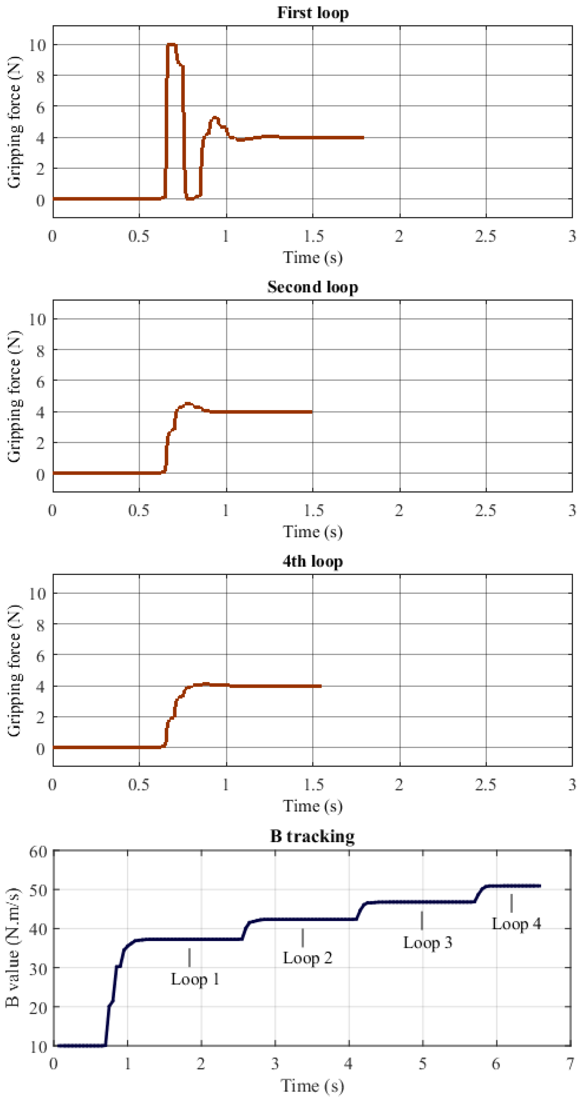
5.1.1. The Data Collection by ILC
5.1.2. The Fuzzy Logic Design
5.1.3. The Evaluation of Fuzzy Impedance Control
5.2. The Experiment
5.2.1. The Data Collection by ILC
5.2.2. The Fuzzy Logic Design
5.2.3. The Evaluation of Fuzzy Impedance Control
5.2.4. Testing the Gripping Force Estimator
5.3. The Comparison
6. Discussions
6.1. The ILC for Data Collection
6.2. The Fuzzy Impedance Control
6.3. The Gripping Force Estimator
6.4. The Comparison
7. Conclusions
Author Contributions
Funding
Conflicts of Interest
References
- Monkman, G.-J.; Hesse, S.; Steimann, R.; Schunk, H. Robot Grippers; Wiley-VCH: Weinheim, Germany, 2006. [Google Scholar]
- Tai, K.; El-Sayed, A.-R.; Shahriari, M.; Biglarbegian, M.; Mahmud, S. State of the Art Robotic Grippers and Applications. Robotics 2016, 5, 11. [Google Scholar] [CrossRef]
- Petković, D.; Danesh, A.-S.; Dadkhah, M.; Misaghian, N.; Shamshirband, S.; Zalnezhad, E.; Pavlović, N.-D. Adaptive Control Algorithm of Flexible Robotic Gripper by Extreme Learning Machine. Robot. Comput. Integr. Manuf. 2016, 37, 170–178. [Google Scholar]
- Datta, R.; Pradhan, S.; Bhattacharya, B. Analysis and Design Optimization of a Robotic Gripper Using Multiobjective Genetic Algorithm. IEEE Trans. Syst. Man Cybern. 2016, 46, 16–26. [Google Scholar] [CrossRef]
- Sadun, A.-S.; Jalani, J.; Sukor, J.-A.; Jamil, F. Force Control for a 3-Finger Adaptive Robot Gripper by Using PID Controller. In Proceedings of the 2016 2nd IEEE International Symposium on Robotics and Manufacturing Automation (ROMA), Ipoh, Malaysia, 25–27 September 2016. [Google Scholar]
- Suebsomran, A. Development of Robot Gripper and Force Control. In Proceedings of the 2018 13th World Congress on Intelligent Control and Automation (WCICA), Changsha, China, 4–8 July 2018; pp. 433–437. [Google Scholar]
- Spiliotopoulos, J.; Michalos, G.; Makris, S. A Reconfigurable Gripper for Dexterous Manipulation in Flexible Assembly. Inventions 2018, 3, 4. [Google Scholar] [CrossRef]
- Ding, Z.; Paperno, N.; Prakash, K.; Behal, A. An Adaptive Control-Based Approach for 1-Click Gripping of Novel Objects Using a Robotic Manipulator. IEEE Trans. Control Syst. Technol. 2019, 27, 1805–1812. [Google Scholar] [CrossRef]
- Zhang, Y.; Xu, Q. Adaptive Sliding Mode Control With Parameter Estimation and Kalman Filter for Precision Motion Control of a Piezo-Driven Microgripper. IEEE Trans. Control Syst. Technol. 2017, 25, 728–735. [Google Scholar] [CrossRef]
- Ikeura, R.; Inooka, H. Variable Impedance Control of a Robot for Cooperation with a Human. In Proceedings of the Proceedings of 1995 IEEE International Conference on Robotics and Automation, Nagoya, Japan, 21–27 May 1995; pp. 3097–3102. [Google Scholar]
- De Gea, J.; Kirchner, F. Modelling and Simulation of Robot Arm Interaction Forces Using Impedance Control. In Proceedings of the 17th World Congress the International Federation of Automatic Control, Seoul, Korea, 6–11 July 2008; pp. 15589–15594. [Google Scholar]
- Caccavale, F.; Chiacchio, P.; Marino, A.; Villani, L. Six-DOF Impedance Control of Dual-Arm Cooperative Manipulators. IEEE/ASME Trans. Mechatron. 2008, 13, 576–586. [Google Scholar] [CrossRef]
- Raiola, G.; Cardenas, C.-A.; Tadele, T.-S.; De Vries, T.; Stramigioli, S. Development of a Safety and Energy-Aware Impedance Controller for Collaborative Robots. IEEE Robot. Autom. Lett. 2018, 3, 1237–1244. [Google Scholar] [CrossRef]
- Park, J.; Choi, Y.-J. Input-to-State Stability of Variable Impedance Control for Robotic Manipulator. Appl. Sci. 2020, 10, 1271. [Google Scholar] [CrossRef]
- Jung, S.; Hsia, T.-C.; Bonitz, R.-G. Force Tracking Impedance Control of Robot Manipulators Under Unknown Environment. IEEE Trans. Control Syst. Technol. 2004, 12, 474–483. [Google Scholar] [CrossRef]
- Li, Z.; Liu, J.; Huang, Z.; Peng, Y.; Pu, H.; Ding, L. Adaptive Impedance Control of Human-Robot Cooperation Using Reinforcement Learning. IEEE Trans. Ind. Electron. 2017, 64, 8013–8022. [Google Scholar] [CrossRef]
- Kim, B.; Park, J.; Park, S.; Kang, S. Impedance Learning for Robotic Contact Tasks Using Natural Actor-Critic Algorithm. IEEE Trans. Syst. Man Cybern. Part B 2010, 40, 433–443. [Google Scholar]
- Li, Y.; Ge, S.-S. Impedance Learning for Robots Interacting with Unknown Environments. IEEE Trans. Control Syst. Technol. 2013, 22, 1422–1432. [Google Scholar] [CrossRef]
- Tran, H.-T.; Cheng, H.; Rui, H.; Lin, X.-C.; Duong, M.-K.; Chen, Q. Evaluation of a Fuzzy-Based Impedance Control Strategy on a Powered Lower Exoskeleton. Int. J. Soc. Robot. 2015, 8, 103–123. [Google Scholar] [CrossRef]
- Roveda, L.; Haghshenas, S.; Prini, A.; Dinon, T.; Pedrocchi, N.; Braghin, F.; Tosatti, L.-M. Fuzzy Impedance Control for Enhancing Capabilities of Humans in Onerous Tasks Execution. In Proceedings of the 2018 15th International Conference on Ubiquitous Robots (UR), Honolulu, HI, USA, 27–30 June 2018; pp. 406–411. [Google Scholar]
- Wong, C.-C.; You, S.-L.; Chen, R.-J.; Liu, Y.-T. Intuitive Teaching of Six-axis Robot Manipulator Based on Fuzzy Impedance Control. In Proceedings of the 2018 International Automatic Control Conference (CACS), Taoyuan, Taiwan, 4–7 November 2018. [Google Scholar]
- Li, M.; Wei, J.; Fang, J.; Shi, W.; Guo, K. Fuzzy Impedance Control of an Electro-Hydraulic Actuator with an Extended Disturbance Observer. Front. Inf. Technol. Electron. Eng. 2019, 20, 1221–1233. [Google Scholar] [CrossRef]
- Lin, C.-T.; Lee, C.-S.-G. Neural Fuzzy Systems-A Neuro-Fuzzy Synergism to Intelligent Systems; Prentice Hall PTR: Upper Saddle River, NJ, USA, 1996. [Google Scholar]
- Freeman, C.-T.; Rogers, E.; Burridge, J.-H. Iterative Learning Control-An Overview. In Iterative Learning Control for Electrical Stimulation and Stroke Rehabilitation; Springer: London, UK, 2015; pp. 3–15. [Google Scholar]
- Moore, K.-L. Iterative Learning Control: An Expository Overview. In Applied and Computational Control, Signals, and Circuits; Springer Science and Business Media: New York, NY, USA, 1999; pp. 151–214. [Google Scholar]
- Morita, N.; Nogami, H.; Higurashi, E.; Sawada, R. Grasping Force Control for a Robotic Hand by Slip Detection Using Developed Micro Laser Doppler Velocimeter. Sensors 2018, 18, 326. [Google Scholar] [CrossRef] [PubMed]
- James, J.-W.; Pestell, N.; Lepora, N.-F. Slip Detection With a Biomimetic Tactile Sensor. IEEE Robot. Autom. Lett. 2018, 3, 3340–3346. [Google Scholar] [CrossRef]
- Su, Z.; Hausman, K.; Chebotar, Y.; Molchanov, A.; Loeb, G.-E.; Sukhatme, G.-S.; Schaal, S. Force Estimation and Slip Detection for Grip Control using a Biomimetic Tactile Sensor. In Proceedings of the 2015 IEEE-RAS 15th International Conference on Humanoid Robots (Humanoids), Seoul, Korea, 3–5 November 2015. [Google Scholar]


| Parameter | Max | MAE |
|---|---|---|
| (N) | 0.2983 | 0.0671 |
| (N) | 0.0503 | 0.0004 |
| Parameter | Max | MAE |
|---|---|---|
| (N) | 0.2866 | 0.0247 |
| (N) | 0.0013 | 0.00021 |
| Parameter | Max | MAE |
|---|---|---|
| (N) | 0.4827 | 0.1173 |
| (N) | 0.3980 | 0.1224 |
| Parameter | Max | MAE |
|---|---|---|
| (N) | 0.4629 | 0.1665 |
| (N) | 0.3862 | 0.1106 |
| Experiment | Case | Object | Gripping Force (N) |
|---|---|---|---|
| 1 | 1 | 61 g egg, 46 mm-diameter, and 59 mm-height | 4 |
| 2 | 8 | ||
| 2 | 1 | 115 g plastic bottle, 55 mm-diameter, and 162 mm-height | 2 |
| 2 | 4 | ||
| 3 | 6 | ||
| 3 | 1 | 636 g metal motor, 42 mm-diameter, 126 mm-height | 3 |
| 2 | 7 |
| Experiment | Case | Force Error (N) | |
|---|---|---|---|
| Proposed Approach | 6 | ||
| 1 | 1 | 0.2270 | 0.6 |
| 2 | 0.3372 | 0.8 | |
| 2 | 1 | 0.1481 | 0.2 |
| 2 | 0.1570 | 0.4 | |
| 3 | 0.2917 | 0.6 | |
| 3 | 1 | 0.2036 | 0.4 |
| 2 | 0.3113 | 0.6 | |
© 2020 by the authors. Licensee MDPI, Basel, Switzerland. This article is an open access article distributed under the terms and conditions of the Creative Commons Attribution (CC BY) license (http://creativecommons.org/licenses/by/4.0/).
Share and Cite
Huynh, B.-P.; Kuo, Y.-L. Optimal Fuzzy Impedance Control for a Robot Gripper Using Gradient Descent Iterative Learning Control in Fuzzy Rule Base Design. Appl. Sci. 2020, 10, 3821. https://doi.org/10.3390/app10113821
Huynh B-P, Kuo Y-L. Optimal Fuzzy Impedance Control for a Robot Gripper Using Gradient Descent Iterative Learning Control in Fuzzy Rule Base Design. Applied Sciences. 2020; 10(11):3821. https://doi.org/10.3390/app10113821
Chicago/Turabian StyleHuynh, Ba-Phuc, and Yong-Lin Kuo. 2020. "Optimal Fuzzy Impedance Control for a Robot Gripper Using Gradient Descent Iterative Learning Control in Fuzzy Rule Base Design" Applied Sciences 10, no. 11: 3821. https://doi.org/10.3390/app10113821
APA StyleHuynh, B.-P., & Kuo, Y.-L. (2020). Optimal Fuzzy Impedance Control for a Robot Gripper Using Gradient Descent Iterative Learning Control in Fuzzy Rule Base Design. Applied Sciences, 10(11), 3821. https://doi.org/10.3390/app10113821