Article

Photoelectrochemical Reduction of CO2 to Syngas by Reduced Ag Catalysts on Si Photocathodes

1
Department of Materials Science and Engineering, Seoul National University, Seoul 08826, Korea
2
School of Chemical Engineering and Materials Science, Chung-Ang University, Seoul 06974, Korea
3
Department of Materials Science and Engineering, Korea University, Seoul 02841, Korea
*
Author to whom correspondence should be addressed.
Appl. Sci. 2020, 10(10), 3487; https://doi.org/10.3390/app10103487
Submission received: 9 April 2020 / Revised: 8 May 2020 / Accepted: 12 May 2020 / Published: 18 May 2020
(This article belongs to the Special Issue Nanomaterials Boosting Solar Water Splitting)

Abstract

:

Featured Application

The new structure of reduced Ag/TiO2/p-Si photocathode has the potential to photoelectrochemically reduce CO2 to syngas for practical applications.

Abstract

The photoelectrochemical reduction of CO2 to syngas that is used for many practical applications has been emerging as a promising technique to relieve the increase of CO2 in the atmosphere. Si has been considered to be one of the most promising materials for photoelectrodes, but the integration of electrocatalysts is essential for the photoelectrochemical reduction of CO2 using Si. We report an enhancement of catalytic activity for CO2 reduction reaction by Ag catalysts of tuned morphology, active sites, and electronic structure through reducing anodic treatment. Our proposed photocathode structure, a SiO2 patterned p-Si photocathode with these reduced Ag catalysts, that was fabricated using electron-beam deposition and electrodeposition methods, provides a low onset-potential of −0.16 V vs. the reversible hydrogen electrode (RHE), a large saturated photocurrent density of −9 mA/cm2 at −1.23 V vs. RHE, and faradaic efficiency for CO of 47% at −0.6 V vs. RHE. This photocathode can produce syngas in the ratio from 1:1 to 1:3, which is an appropriate proportion for practical application. This work presents a new approach for designing photocathodes with a balanced catalytic activity and light absorption to improve the photoelectrochemical application for not only CO2 reduction reaction, but also water splitting or N2 reduction reaction.

Graphical Abstract

1. Introduction

The uncontrollable increase of CO2 in the atmosphere by the excessive consumption of fossil fuels has become an urgent environmental issue in the world, as it has been considered a primary cause of global warming [1,2,3,4]. Because of this reason, the conversion of CO2 to useful low carbon fuels has attracted considerable research interest [5,6,7]. Among the various methods, the photoelectrochemical (PEC) reduction of CO2 has been regarded as a promising strategy because it utilizes solar energy and water to reduce CO2, which mimics natural photosynthesis [8,9]. Depending on the catalysts and conditions, diverse chemicals, such as carbon monoxide, formic acid, or hydrocarbons can be produced [10,11,12,13,14,15]. In aqueous electrolytes, the competitive hydrogen evolution reaction, which produces hydrogen gas, may occur together with the CO2 reduction reaction. Therefore, syngas (synthesis gas, CO, and H2 mixtures) can be obtained in aqueous electrolytes, which is a critical C1 feedstock for practical applications, including Fischer–Tropsch synthesis, methanol synthesis, and syngas fermentation [16,17].
In the PEC system, many kinds of semiconductors, such as Si, oxide, nitride, and sulfide, have been studied for highly efficient PEC CO2 reduction reactions [8,18,19,20,21,22,23]. Among the semiconductors, p-Si is known as one of the most promising materials for photocathodes because of its narrow bandgap of 1.1 eV, earth abundance, and high-level processing technique. However, unfortunately, since the catalytic activity of Si for CO2 reduction reaction is poor, a high over-potential is needed to reduce CO2 on Si photocathodes [18,24]. Therefore, for highly efficient syngas production using an Si photocathode, catalysts that have high catalytic activity for a CO2 reduction reaction are essential. Metals such as Au and Ag have been known to promote the conversion of CO2 to CO by electrochemical reduction in aqueous electrolytes [11,25,26,27]. Furthermore, the catalytic activity of these metals varies depending on the size of catalysts, morphology, crystallinity, oxidation states of metal catalysts [11,28,29,30,31]. Kanan’s group first demonstrated the enhancement of catalytic activity for CO2 reduction reaction of metal catalysts by tuning the nanostructure and the oxidation states of metals through electrochemical reduction of metal oxides in 2012 [11,32,33]. The oxide derived Au electrode exhibited remarkable performance, with a very low over-potential of 140 mV and high selectivity for CO production of 98%. However, although Au electrodes have better catalytic activity than Ag electrodes, their application on the industrial scale is difficult because of the high cost of Au metal. For this reason, many kinds of electrochemical treatments on Ag electrodes have been studied as replacement of Au electrodes, such as oxide-derived Ag [34], Ag2CO3-derived Ag [35,36], AgCl-derived Ag [37], and AgBr-derived Ag [38]. With these Ag catalysts, efficient and low-cost PEC CO2 reduction to syngas using Si photocathodes could be realized. However, because Ag catalysts inhibit the light absorption onto Si photocathode, there is a trade-off between the selectivity for CO and the light absorption. Therefore, an appropriate structure for photocathodes is needed [8,18].
In this study, we demonstrate the enhancement of Ag catalysts by reducing anodic (RA) treatment applied on p-Si photocathodes for efficient PEC CO2 reduction to produce syngas in an aqueous electrolyte. Through the RA treatment, the properties of Ag catalysts, such as morphology, active sites, and electronic structure, are tuned to achieve high catalytic activity for the CO2 reduction reaction. Furthermore, we propose a new structure for photocathode using SiO2 patterning, which balances the catalytic activity for CO2 reduction reaction and light absorption onto the Si photocathode. Figure 1a shows the schematic of the proposed photoelectrochemical reduction of CO2 into syngas on the reduced Ag (R-Ag)/TiO2/p-Si photocathode. The R-Ag/TiO2/p-Si photocathode provides a low onset potential of −0.16 V vs. RHE (reversible hydrogen electrode), a large saturated photocurrent density of −9 mA/cm2 at −1.23 V vs. RHE. Finally, the syngas in ratio from 1:1 to 1:3 that can be used to practical application is produced depending on the various applied potentials.

2. Materials and Methods

2.1. Synthesis

2.1.1. Fabrication of Ag/TiO2/p-Si Photocathode and SiO2 Patterned Ag/TiO2/p-Si Photocathode

A p-Si wafer (0.01–0.1 Ω-m, <100> plane, DASOMRMS Co., Ltd., Korea) was cleaned in acetone, isopropyl alcohol, and deionized (DI) water, using ultrasonication. The water was purified by a water purification system (Human Power, Human Co, Ltd., 183 KΩ-m, Korea) for DI water. The cleaned p-Si wafer was soaked for 1 min in 5% hydrofluoric acid (HF) to etch the native SiO2 layers. Then, a 5 nm thick TiO2 thin film was deposited using an electron-beam evaporator (KVE-E2004L, KOVA, Korea). Subsequent heat treatment was conducted for TiO2/p-Si substrates in a tube furnace at 350 °C for 30 min under N2. For SiO2 patterned Ag/TiO2/p-Si photocathode, after deposition of TiO2 thin film, a patterned 500 nm-thick SiO2 was deposited using the electron-beam evaporator, using a patterning mask (Supplementary Figure S1a). The patterning mask has square holes of 500 μm in length, and their total area is 50% of the total area of the mask. Before the electrodeposition, a Cu wire was connected to the scratched backside of the TiO2/p-Si substrate using an In-Ga alloy (Sigma Aldrich) and silver paste. Then, except for the active area of 1 × 1 cm, the whole surface of the TiO2/p-Si surface was covered with an adhesive Kapton tape to prevent contact with the electrolyte.
The solution for the deposition of Ag is prepared from 5 mM AgNO3, 50 mM NaNO3, which were dissolved in DI water. The Ag catalysts were electrodeposited on the TiO2/p-Si electrodes in a standard three-electrode system with a Pt mesh as a counter electrode and Ag/AgCl (sat. KCl) as a reference electrode. The deposition of Ag was performed by applying −0.1 V vs. Ag/AgCl on the working electrode for 15 min. Then, the electrodeposited samples were rinsed with DI water.

2.1.2. RA Treatment for R-Ag/TiO2/p-Si Photocathode and SiO2 Patterned R-Ag/TiO2/p-Si Photocathode

The RA treatment was performed on (SiO2 patterned) Ag/TiO2/p-Si photocathodes in CO2-saturated 0.1 M KHCO3 electrolyte (pH 6.7) in a two-compartment H-type electrochemical cell with a Pt mesh counter electrode and an Ag/AgCl (sat. KCl) reference electrode. Symmetric 50 Hz square-wave pulses between 1.3 V and 0.1 V were applied for 60 min. After pulsed anodization, the reduction of Ag catalysts was conducted at −0.6 V vs. RHE for 10 min.

2.2. Materials Characterization

The morphology of the fabricated photocathodes was studied using FE-SEM (SUPRA 55VP), with an acceleration voltage of 2 kV and the working distance of 3.5 mm. The structural study of Ag and R-Ag on a TiO2/p-Si photocathode was confirmed by a Bruker D8 advance diffractometer, equipped with a Cu Kα source. XPS analysis was carried out using an instrument (SIGMA PROBE ThermoFisher Scientific, UK) at a base pressure of 5 × 10⁻¹⁰ mbar at 300 K using monochromatic Al Kα radiation (1486.6 eV) generated from an electron beam operated at 15 kV. The binding energy (BE) scale was calibrated with the C 1s peak being at 284.5 eV. The spot size was about 400 μm.

2.3. Electrochemical Characterization

The PEC measurements (Ivium Technologies, Nstat, Netherlands) were carried out with a three-electrode system with a Pt mesh as a counter electrode and an Ag/AgCl (sat. KCl) reference electrode in a CO2 saturated KHCO3 electrolyte. All measurements are conducted in the two-compartment H-type electrochemical cell with a piece of proton exchange membrane (Nafion® 117, Sigma-Aldrich) as the separator. Before measurement, the electrolytes in the H-type cell were purged with CO2 gas for at least 30 min. A Xe arc lamp used as a light source was calibrated to 1 sun (100 mW/cm2, AM 1.5 G) using a reference photodiode. For the linear sweep with a cathodic direction, a scan rate of 20 mV/s was used. The measured current density was normalized to the electrode geometrical area. The measured potential vs. Ag/AgCl was converted to the RHE scale according to the Nernst equation:
E R H E = E A g / A g C l + 0.059 × p H + E A g / A g C l 0
where ERHE is the potential vs. RHE, E0Ag/AgCl = 0.198 V at 25 °C, and EAg/AgCl is the measured potential vs. the Ag/AgCl reference electrode.
The evolved gas was analyzed using gas chromatography (Agilent GC 7890B, Agilent Technologies, Inc., United States) connected to the cathodic compartment of an H-type electrochemical cell while a constant potential was applied. A 20.0 sccm rate of CO2 gas was delivered into the cathodic compartment and vented into the gas sampling loop of the GC. The GC was equipped with a micropacked column (ShinCarbon ST 100/120), a thermal conductivity detector (TCD), and a flame ionization detector (FID), with argon as the carrier gas. The faradaic efficiency was calculated according to the following equations:
j C O = p e a k   a r e a   o f   C O α × f l o w   r a t e × 2 F p 0 R T × ( e l e c t r o d e   a r e a ) - 1
j H 2 = p e a k   a r e a   o f   C O β × f l o w   r a t e × 2 F p 0 R T × ( e l e c t r o d e   a r e a ) - 1
F . E . C O = j C O / j m e a s u r e d
F . E . H 2 = j H 2 / j m e a s u r e d
where α and β are conversion factors for CO and H2, respectively, based on calibrations of the GC with a standard sample, p0 = 101.325 kPa, and T = 298.15 K.
To compare the electrochemical surface area, double layer capacitance of R-Ag and Ag catalysts was measured on TiO2/p-Si substrate in 0.1 M KHCO3 electrolytes according to previously published method [39]. The charging current was measured from the CVs at different scan rates (10–100 mV s−1). The relation between the double layer capacitance, the charging current, and the scan rate is given Equation (6).
i c = v C D L
where ic, v, and CDL are charging current, scan rate, and double layer capacitance, respectively.

3. Results and Discussion

The Ag/TiO2/p-Si photocathode is synthesized by using the combination of electron-beam deposition and electrodeposition method. At first, a TiO2 thin-film was deposited on p-Si substrate with 5 nm thickness using an electron-beam evaporator. The obtained TiO2/p-Si substrate was annealed in a tube furnace at 350 °C for 30 min under N2 atmosphere. After that, Ag catalysts are deposited on the TiO2/p-Si substrate through the electrodeposition method. For the fabrication of R-Ag/TiO2/p-Si, electrochemical RA treatment was conducted on the Ag/TiO2/p-Si substrate. A Field-emission scanning electron microscopy (FE-SEM) was conducted to investigate the surface morphology changes induced by the RA treatment. Figure 1b–e shows the SEM images of the fabricated Ag/TiO2/p-Si photocathode and R-Ag/TiO2/p-Si photocathode. Figure 1b,c shows the morphology of Ag/TiO2/p-Si photocathode, which presented Ag particles of several hundred nanometers to micrometers in size have polygonal shapes. After pulsed anodization, the particles are merged into bigger particles randomly shaped (Supplementary Figure S2). However, as shown in Figure 1d,e, the reduction of Ag particles turned the Ag particles to change into the porous-like nanostructures on R-Ag/TiO2/p-Si photocathode. Compared with the Ag/TiO2/p-Si photocathode, the surface area of R-Ag/TiO2/p-Si photocathode was enlarged, and the flat surface of Ag particles was changed into the rough surface. To estimate the change of surface area, the double layer capacitance (Cdl) at the solid/liquid interface for R-Ag/TiO2/p-Si and Ag/TiO2/p-Si photocathodes was measured by the cyclic voltammetry technique using different scan rates as shown in Figure S3a,b. Supplementary Figure S3c shows that the R-Ag/TiO2/p-Si photocathode exhibited a higher Cdl of 0.18 mF cm−2 than the Ag/TiO2/p-Si photocathode of 0.018 mF cm−2, indicating that more active surface area has increased through the RA treatment.
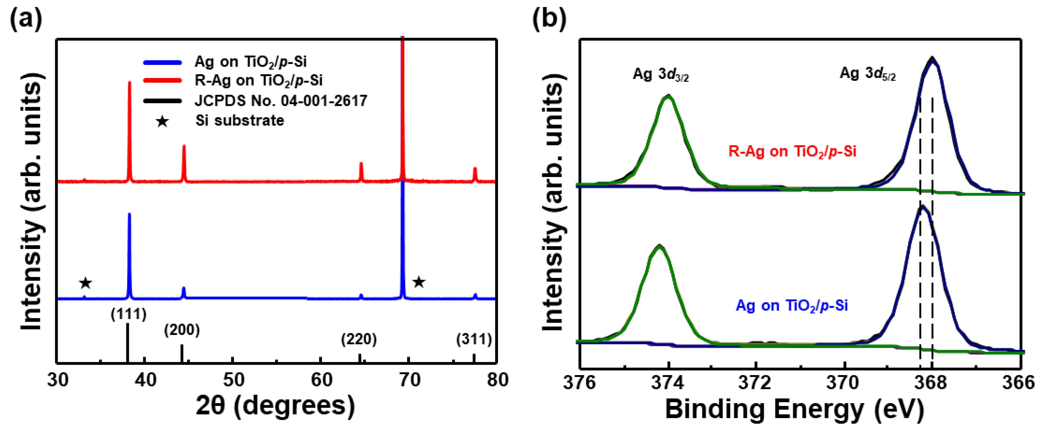
To investigate the changes of the crystalline structure after RA treatment, the Ag/TiO2/p-Si photocathode and the R-Ag/TiO2/p-Si photocathode were analyzed by X-ray diffraction (XRD). Figure 2a displays the XRD patterns of the Ag and R-Ag catalysts on TiO2/p-Si photocathodes. XRD patterns for these two photocathodes show 2θ reflection peaks at 38.2°, 44.5°, 64.5°, and 77.5° which all correspond to diffractions along the (111), (200), (220), and (311) planes of the face-centered cubic Ag crystal structure. The Ag/TiO2/p-Si photocathode has the intense (111) peak, suggesting a preferred crystal orientation. However, XRD patterns for R-Ag/TiO2/p-Si photocathode became more randomly powder-like Ag reference peaks with relative increase of (200), (220), and (311) peaks compared to the Ag/TiO2/p-Si photocathode. Therefore, it was confirmed that not only the morphology was changed, but also the crystallinity of the Ag catalysts through RA treatment. Previously, the catalytic activity for electrochemical CO2 reduction to CO was higher on the (110) plane than on (111) or (100) planes, because of higher density of undercoordinated active sites [31,40]. For face-centered cubic structures, (110) plane cannot be observable in XRD patterns because the (110) reflection does not occur. Assuming that the amount of the (110) plane exists in proportion to that of the (220) plane, it can be deduced that the amount of the (110) plane is increased in the R-Ag/TiO2/p-Si photocathode after RA treatment. Therefore, it is expected that the electrochemical reduction of CO2 efficiency can be enhanced by RA treatment due to an increase of the active sites on (220) planes.
Furthermore, the electronic structures of the Ag and R-Ag on TiO2/p-Si photocathode were analyzed through X-ray photoelectron spectroscopy (XPS). XPS survey spectra for Ag and R-Ag on TiO2/p-Si photocathode was shown in Supplementary Figure S4. In Figure 2b, for Ag/TiO2/p-Si photocathode, the Ag 3d5/2 peak and Ag 3d3/2 peak were observed at 368.2 eV and 374.2 eV, respectively. Also, R-Ag/TiO2/p-Si photocathode has Ag 3d peaks at 368 eV and 374 eV, which are assigned to Ag 3d5/2 and Ag 3d3/2 peaks, respectively. The Ag 3d peaks could be deconvoluted into one main peak, which shows there is only metallic Ag. However, the Ag 3d peaks of the R-Ag/TiO2/p-Si photocathode were slightly shifted to lower binding energy than that of the Ag/TiO2/p-Si photocathode. The negative shifts of core-level binding energy are induced by increased electron density on the Ag surface by intermetallic electron transfer, which is reported to improve the catalytic activity for electrochemical CO2 reduction to CO on Ag catalysts [36,41]. Rodriguez et al. have shown that a decrease in core-level binding energy causes strong chemisorption of CO because the high electron density of host metal facilitates π-backdonation into adsorbed CO [42]. As a result, the negative shift in core-level binding energy stabilizes the most important reaction intermediate (COOH*) on Ag catalysts due to the scaling relation. Therefore, due to the downshift of the binding energy by the RA treatment, the performance improvement of electrochemical CO2 reduction to CO can occur on the R-Ag catalysts compared to Ag catalysts on TiO2/p-Si photocathodes.
For PEC measurement, the 500 nm thick patterned SiO2 layer was deposited on TiO2/p-Si substrates using a patterning mask (Supplementary Figure S1a), followed by electrodeposition of Ag catalysts in the same procedure mentioned earlier. In Supplementary Figure S1b,c, Ag catalysts were electrodeposited only on the SiO2-free surface of the TiO2/p-Si substrate, allowing light absorption to Si through the SiO2 portion. The high electronic potential barrier is formed at the TiO2/SiO2 interface due to the high band gap of SiO2, so electrons for electrodeposition of Ag+ ion to Ag cannot be move to the electrolyte. Therefore, Ag catalysts are only deposited on the SiO2-free surface.
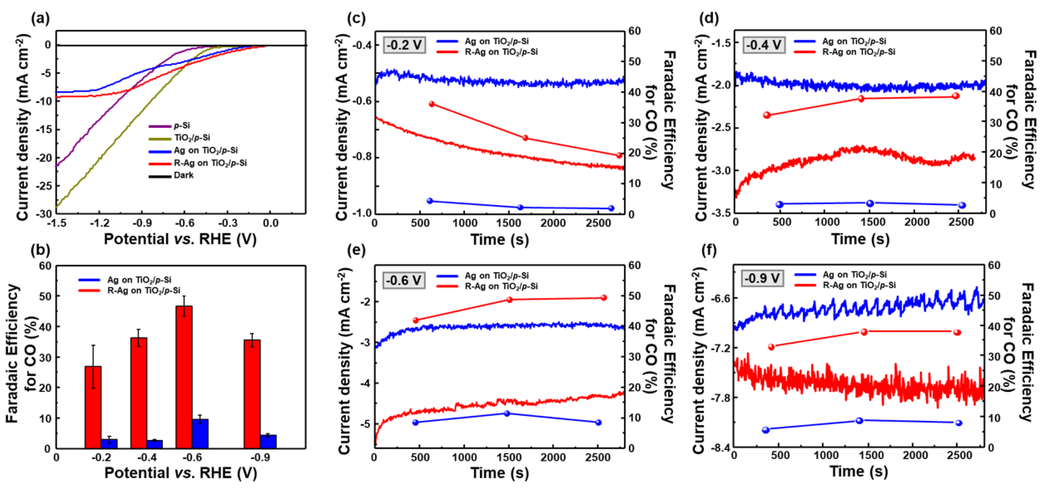
The PEC properties of the R-Ag on TiO2/p-Si, Ag on TiO2/p-Si, TiO2/p-Si, and p-Si photocathodes were measured with a three-electrode system in CO2 saturated 0.1 M KHCO3 electrolytes under AM 1.5 G illumination. Figure 3a displays the PEC current densities of the photocathodes plotted as a function of potential vs. RHE. The black lines indicate the dark current, which show negligible currents flows in the dark condition. As in the previous report [43], when the onset potential means a voltage generating a photocurrent of −0.6 mA/cm2, the p-Si photocathode is found to have the largest onset potential of −0.54 V vs. RHE. The TiO2/p-Si photocathode has a slightly enhanced onset potential of −0.42 V vs. RHE and larger photocurrent, which is attributed to a heterojunction formed with p-Si and n-TiO2 [44]. On the other hand, the two Ag-electrodeposited photocathodes exhibit the significantly lowered onset potential, and the R-Ag/TiO2/p-Si photocathode exhibits the lowest onset potential of −0.16 V vs. RHE, which is 100 mV lower than that of the Ag/TiO2/p-Si photocathode. After the onset potential, the photocurrent density of the R-Ag/TiO2/p-Si photocathode gradually rises with the applied potential and is saturated to −9 mA/cm2 at −1.23 V vs. RHE, which is superior to that of the Ag/TiO2/p-Si photocathode. Compared to the p-Si and TiO2/p-Si photocathodes, the photocurrent density of Ag catalysts electrodeposited photocathodes is reduced due to the Ag particles that inhibited the light absorption by the light absorber, but an enhancement of the catalytic activity occurs on the Ag catalysts.
To obtain faradaic efficiency, chronoamperometric measurements were conducted at potentials between −0.4 and −0.9 V vs. RHE while gas products are analyzed three times at each potential using gas chromatography (GC). The faradaic efficiency is calculated based on Equations (2)–(5) using the corresponding chronoamperometry (it) curves in Figure 3c–f. The average values of calculated faradaic efficiency for CO were plotted against the potential, as shown in Figure 3b. The p-Si and TiO2/p-Si photocathodes have a very low faradaic efficiency of less than 5% at all the measured potentials in Supplementary Figure S5, because Si has poor CO2 reduction reaction catalytic activity and TiO2 has catalytic properties for hydrogen evolution reaction [18,44]. Although Ag catalysts were introduced, it is confirmed that the Ag/TiO2/p-Si photocathode still exhibit a low selectivity. However, with the RA treatment of Ag catalysts, the selectivity for CO is considerably improved at R-Ag/TiO2/p-Si photocathode, as shown in Figure 3b. At the low potential of −0.2 V vs. RHE, the R-Ag/TiO2/p-Si photocathode has a faradaic efficiency of 27%. With the increasing applied potential, the CO selectivity gradually rose and reached 47% at −0.6 V vs. RHE, and decreased beyond the peak potential. Before the potential region of −0.6 V vs. RHE, the hydrogen evolution reaction is suppressed by CO adsorbed on Ag catalysts, causing the faradaic efficiency for CO to increase [31]. However, beyond the −0.6 V vs. RHE, the faradaic efficiency for CO decreased. This is due to reaching the mass transport limitation of CO2 by the low concentration of CO2 in the aqueous electrolyte at higher over-potential [45]. In Figure 3c–f, the photocurrent density on the R-Ag/TiO2/p-Si photocathode is larger than that on the Ag/TiO2/p-Si photocathode over all measured potential. This is due to the enlarged active sites by morphology changes. Furthermore, the enhancement of faradaic efficiency for CO is attributed to the increased (110) planes and lower binding energy of R-Ag catalysts as mentioned before. The undercoordinated surface atom on (110) planes and lowered binding energy of R-Ag could facilitate the stabilization of the key reaction intermediate (COOH*).
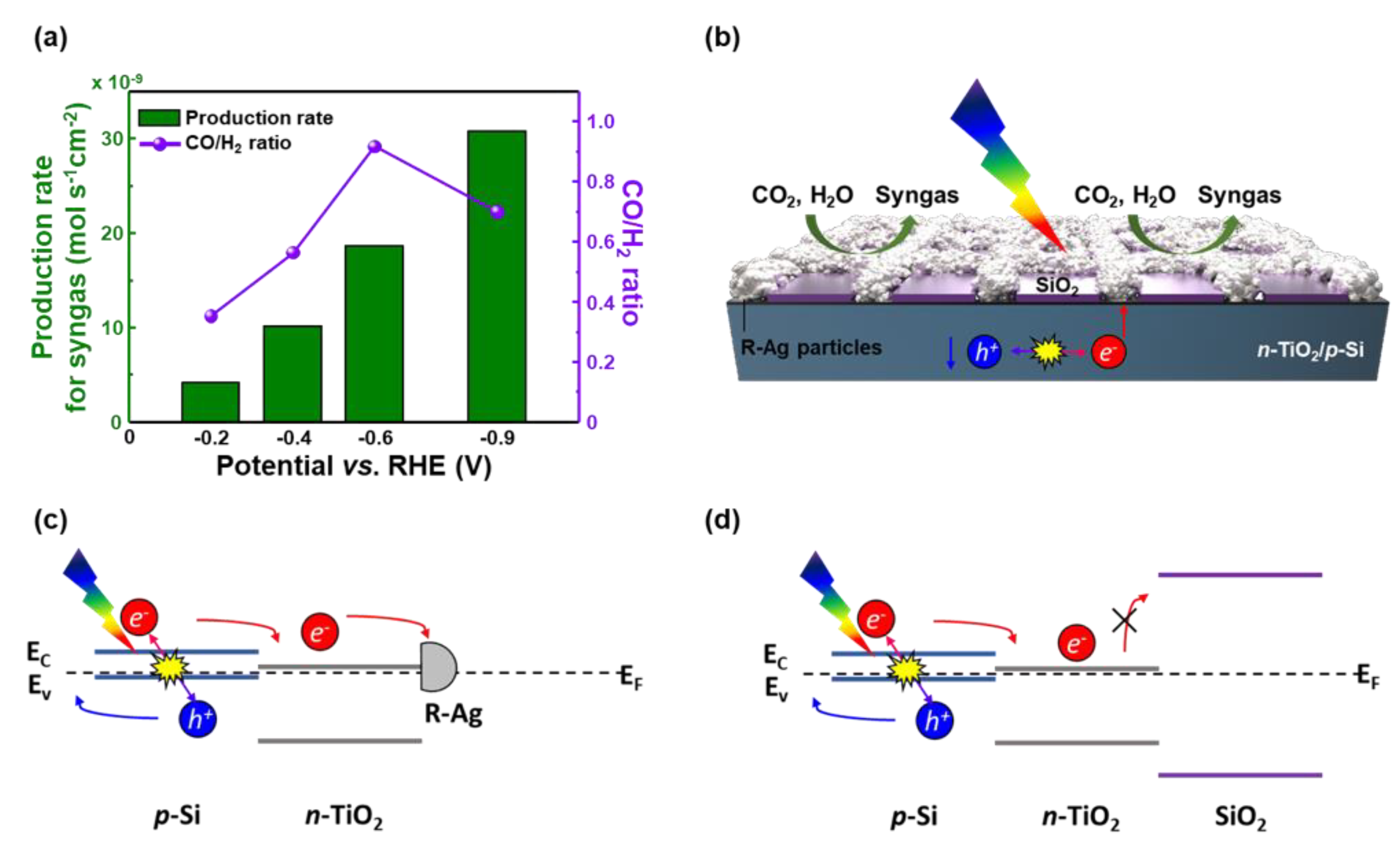
The best-performing R-Ag/TiO2/p-Si photocathode can synthesis syngas with ratios from 1:3 to 1:1 depends on the applied potentials, as shown in Figure 4a. At −0.4 V vs. RHE, the photocathode produces 10.1 mol/s∙cm2 of syngas at a ratio of 1:2, which is suitable feedstock for the process of methanol production [46]. Also, the syngas with a ratio of 1:1 is produced at a rate of 18.6 mol/s∙cm2 at −0.6 V vs. RHE, which can be used for the Fischer-Tropsch synthesis [47]. Furthermore, the stability test was conducted at −0.4 V vs. RHE for the R-Ag/TiO2/p-Si photocathode. Supplementary Figure S6 shows the excellent stability for the R-Ag/TiO2/p-Si photocathode indicating no significant decreases in both current density and faradaic efficiency for CO.
This PEC performance for syngas production on Ag catalysts is realized by using the model proposed here. Figure 4b shows the schematic of our proposed model of photocathode for CO2 reduction. This model, patterning SiO2 layer and filling the remaining region with Ag catalysts using the electrodeposition method, can allow the light absorption through the SiO2 layer and promote the CO2 reduction reaction on Ag catalysts.
This is attributed to the energy band structure of the photocathode, as shown in Figure 4c,d. The band diagrams were drawn based on the previously reported flat band diagrams [44,48,49,50] (Figure S7). SiO2 is an insulating material, and thus has a high band gap. Due to the intrinsic energy band property of SiO2, the high electronic potential barrier is formed at the Ag/SiO2 interface, which blocked transportation of the electrons to electrolyte for reaction. On the other hand, since Ag particles have metallic properties, the electrons are easily transferred through Ag particles to electrolyte. Therefore, the electrochemical reaction only occurs at the R-Ag catalysts, which improves the efficiency of CO2 reduction reaction. Furthermore, this model can be adapted to other catalysts, so it can be seen as a promising model for photocathode on PEC CO2 reduction study.

4. Conclusions

In this article, we report for the reduced Ag catalysts on TiO2/p-Si photocathodes for PEC CO2 reduction to produce syngas. The R-Ag/TiO2/p-Si photocathode has been synthesized by using the combination of electron-beam deposition method, electrodeposition, and electrochemical anodization/reduction treatment. The morphology, active sites, and electronic structure of Ag catalysts are modified by the RA treatment to achieve the high catalytic activity for the CO2 reduction reaction. The new model using a patterned SiO2 layer can allow the light absorption onto light absorber and facilitate the CO2 reduction reaction on Ag catalysts. The best performing photocathode provided the lowest onset potential of −0.16 V vs. RHE, with a large saturated photocurrent density of −9 mA/cm2 at −1.23 V vs. RHE. Furthermore, the faradaic efficiency for CO of 47% was achieved at −0.6 V vs. RHE. At this potential, the photocathode could produce the syngas ratio of 1:1 with the rate in 18.6 mol/s∙cm2, which is a suitable proportion for the Fischer–Tropsch synthesis. Although this study focused on p-Si photocathode with Ag catalysts for PEC CO2 reduction, our proposed new model for a photocathode could be useful in various PEC applications, such as hydrogen evolution reaction, oxygen evolution reaction, or N2 reduction reaction.

Supplementary Materials

The following are available online at https://www.mdpi.com/2076-3417/10/10/3487/s1, Figure S1: (a) Patterning mask used for deposition of SiO2 layer. (b,c) SEM images and EDS spectrum of partially electrodeposited Ag particles on SiO2-free region on Ag/TiO2/p-Si photocathode., Figure S2: Scanning electron microscopic (SEM) images of anodized Ag catalysts on TiO2/p-Si photocathodes in (a) low and (b) high magnification., Figure S3: CV curves for (a) R-Ag/TiO2/p-Si and (b) Ag/TiO2/p-Si photocathodes at scan rate of 10, 20, 40, 60, 80, and 100 mV s−1 in 0.1 M KHCO3 electrolytes. (c) Corresponding capacitive currents at 0.7 V vs. RHE plotted against the scan rate for R-Ag/TiO2/p-Si and Ag/TiO2/p-Si photocathodes., Figure S4: XPS survey spectrum for (a) Ag/TiO2/p-Si and (b) R-Ag/TiO2/p-Si photocathodes., Figure S5: The faradaic efficiency of the p-Si and TiO2/p-Si photocathodes under 1 Sun illumination (AM 1.5 G) in CO2-saturated 0.1 M KHCO3 electrolytes., Figure S6: Stability test of current density and CO faradaic efficiency for R-Ag/TiO2/p-Si photocathode at −0.4 V vs. RHE under 1 sun illumination (AM 1.5 G) in CO2-saturated 0.1 M KHCO3 electrolytes., Figure S7: Flat band diagram of (a) p-Si, (b) n-TiO2, and (c) SiO2.

Author Contributions

Conceptualization, H.W.J. and C.K; methodology, C.K.; validation, C.K.; formal analysis, C.K. and S.C.; investigation, C.K.; resources, C.K., M.-J.C., S.A.L.; data curation, C.K.; writing—original draft preparation, C.K.; writing—review and editing, C.K.; visualization, C.K.; supervision, H.W.J.; project administration, H.W.J.; funding acquisition, H.W.J., S.H.A., S.Y.K. All authors have read and agreed to the published version of the manuscript.

Funding

This work was financially supported by the Basic Research Laboratory (2018R1A4A1022647) and the National Research Foundation of Korea (NRF) grant funded by the Korean government MSIT (2019M3E6A1103818).

Conflicts of Interest

The authors declare no conflict of interest.

References

  1. Davis, S.J.; Caldeira, K.; Matthews, H.D. Future CO2 emissions and climate change from existing energy infrastructure. Science 2010, 329, 1330–1333. [Google Scholar] [CrossRef] [PubMed] [Green Version]
  2. Feldman, D.R.; Collins, W.D.; Gero, P.J.; Torn, M.S.; Mlawer, E.J.; Shippert, T.R. Observational determination of surface radiative forcing by CO2 from 2000 to 2010. Nature 2015, 519, 339–343. [Google Scholar] [CrossRef] [PubMed] [Green Version]
  3. Montoya, J.H.; Seitz, L.C.; Chakthranont, P.; Vojvodic, A.; Jaramillo, T.F.; Nørskov, J.K. Materials for solar fuels and chemicals. Nat. Mater. 2017, 16, 70–81. [Google Scholar] [CrossRef] [PubMed]
  4. Lee, M.G.; Jin, K.; Kwon, K.C.; Sohn, W.; Park, H.; Choi, K.S.; Go, Y.K.; Seo, H.; Hong, J.S.; Nam, K.T.; et al. Efficient water splitting cascade photoanodes with ligand-engineered MnO cocatalysts. Adv. Sci. 2018, 5, 1800727. [Google Scholar] [CrossRef] [PubMed] [Green Version]
  5. Kondratenko, E.V.; Mul, G.; Baltrusaitis, J.; Larrazábal, G.O.; Pérez-Ramírez, J. Status and perspectives of CO2 conversion into fuels and chemicals by catalytic, photocatalytic and electrocatalytic processes. Energy Environ. Sci. 2013, 6, 3112–3135. [Google Scholar] [CrossRef] [Green Version]
  6. Kim, S.; Dong, W.J.; Gim, S.; Sohn, W.; Park, J.Y.; Yoo, C.J.; Jang, H.W.; Lee, J.-L. Shape-controlled bismuth nanoflakes as highly selective catalysts for electrochemical carbon dioxide reduction to formate. Nano Energy 2017, 39, 44–52. [Google Scholar] [CrossRef]
  7. Kwon, K.C.; Suh, J.M.; Varma, R.S.; Shokouhimehr, M.; Jang, H.W. Electrocatalytic water splitting and CO2 reduction: Sustainable solutions via single-atom catalysts supported on 2D materials. Small Methods 2019, 3, 1800492. [Google Scholar] [CrossRef]
  8. Ding, P.; Hu, Y.; Deng, J.; Chen, J.; Zha, C.; Yang, H.; Han, N.; Gong, Q.; Li, L.; Wang, T. Controlled chemical etching leads to efficient silicon–bismuth interface for photoelectrochemical CO2 reduction to formate. Mater. Today Chem. 2019, 11, 80–85. [Google Scholar] [CrossRef]
  9. Kong, Q.; Kim, D.; Liu, C.; Yu, Y.; Su, Y.; Li, Y.; Yang, P. Directed assembly of nanoparticle catalysts on nanowire photoelectrodes for photoelectrochemical CO2 reduction. Nano Lett. 2016, 16, 5675–5680. [Google Scholar] [CrossRef]
  10. Hori, Y.; Wakebe, H.; Tsukamoto, T.; Koga, O. Electrocatalytic process of CO selectivity in electrochemical reduction of CO2 at metal electrodes in aqueous media. Electrochim. Acta 1994, 39, 1833–1839. [Google Scholar] [CrossRef]
  11. Chen, Y.; Li, C.W.; Kanan, M.W. Aqueous CO2 reduction at very low overpotential on oxide-derived Au nanoparticles. J. Am. Chem. Soc. 2012, 134, 19969–19972. [Google Scholar] [CrossRef] [PubMed]
  12. Zhang, Y.; Li, F.; Zhang, X.; Williams, T.; Easton, C.D.; Bond, A.M.; Zhang, J. Electrochemical reduction of CO2 on defect-rich Bi derived from Bi2S3 with enhanced formate selectivity. J. Mater. Chem. A 2018, 6, 4714–4720. [Google Scholar] [CrossRef]
  13. Le, M.; Ren, M.; Zhang, Z.; Sprunger, P.T.; Kurtz, R.L.; Flake, J.C. Electrochemical reduction of CO2 to CH3OH at copper oxide surfaces. J. Electrochem. Soc. 2011, 158, E45–E49. [Google Scholar] [CrossRef]
  14. Barton, E.E.; Rampulla, D.M.; Bocarsly, A.B. Selective solar-driven reduction of CO2 to methanol using a catalyzed p-GaP based photoelectrochemical cell. J. Am. Chem. Soc. 2008, 130, 6342–6344. [Google Scholar] [CrossRef] [PubMed]
  15. Choi, S.; Kim, C.; Suh, J.M.; Jang, H.W. Reduced graphene oxide-based materials for electrochemical energy conversion reactions. Carbon Energy 2019, 1, 85–108. [Google Scholar] [CrossRef] [Green Version]
  16. Khodakov, A.Y.; Chu, W.; Fongarland, P. Advances in the development of novel cobalt Fischer—Tropsch catalysts for synthesis of long-chain hydrocarbons and clean fuels. Chem. Rev. 2007, 107, 1692–1744. [Google Scholar] [CrossRef]
  17. Foit, S.R.; Vinke, I.C.; de Haart, L.G.; Eichel, R.A. Power-to-Syngas: An Enabling Technology for the Transition of the Energy System? Angew. Chem. Int. Ed. 2017, 56, 5402–5411. [Google Scholar] [CrossRef]
  18. Song, J.T.; Ryoo, H.; Cho, M.; Kim, J.; Kim, J.G.; Chung, S.Y.; Oh, J. Nanoporous Au thin films on Si photoelectrodes for selective and efficient photoelectrochemical CO2 reduction. Adv. Energy Mater. 2017, 7, 1601103. [Google Scholar] [CrossRef]
  19. Kang, H.-Y.; Nam, D.-H.; Yang, K.D.; Joo, W.; Kwak, H.; Kim, H.-H.; Hong, S.-H.; Nam, K.T.; Joo, Y.-C. Synthetic Mechanism Discovery of Monophase Cuprous Oxide for Record High Photoelectrochemical Conversion of CO2 to Methanol in Water. ACS Nano 2018, 12, 8187–8196. [Google Scholar] [CrossRef]
  20. Yang, X.; Fugate, E.A.; Mueanngern, Y.; Baker, L.R. Photoelectrochemical CO2 reduction to acetate on iron-copper oxide catalysts. ACS Catal. 2017, 7, 177–180. [Google Scholar] [CrossRef]
  21. DuChene, J.S.; Tagliabue, G.; Welch, A.J.; Cheng, W.-H.; Atwater, H.A. Hot hole collection and photoelectrochemical CO2 reduction with plasmonic Au/p-GaN photocathodes. Nano Lett. 2018, 18, 2545–2550. [Google Scholar] [CrossRef] [PubMed] [Green Version]
  22. Asadi, M.; Motevaselian, M.H.; Moradzadeh, A.; Majidi, L.; Esmaeilirad, M.; Sun, T.V.; Liu, C.; Bose, R.; Abbasi, P.; Zapol, P.; et al. Highly Efficient Solar-Driven Carbon Dioxide Reduction on Molybdenum Disulfide Catalyst Using Choline Chloride-Based Electrolyte. Adv. Energy Mater. 2019, 9, 1803536. [Google Scholar] [CrossRef]
  23. Kim, T.L.; Choi, M.-J.; Lee, T.H.; Sohn, W.; Jang, H.W. Tailoring of Interfacial Band Offsets by an Atomically Thin Polar Insulating Layer To Enhance the Water-Splitting Performance of Oxide Heterojunction Photoanodes. Nano Lett. 2019, 19, 5897–5903. [Google Scholar] [CrossRef] [PubMed]
  24. Hinogami, R.; Nakamura, Y.; Yae, S.; Nakato, Y. An approach to ideal semiconductor electrodes for efficient photoelectrochemical reduction of carbon dioxide by modification with small metal particles. J. Phys. Chem. B 1998, 102, 974–980. [Google Scholar] [CrossRef]
  25. Rogers, C.; Perkins, W.S.; Veber, G.; Williams, T.E.; Cloke, R.R.; Fischer, F.R. Synergistic enhancement of electrocatalytic CO2 reduction with gold nanoparticles embedded in functional graphene nanoribbon composite electrodes. J. Am. Chem. Soc. 2017, 139, 4052–4061. [Google Scholar] [CrossRef] [Green Version]
  26. Zhang, L.; Wang, Z.; Mehio, N.; Jin, X.; Dai, S. Thickness-and Particle-Size-Dependent Electrochemical Reduction of Carbon Dioxide on Thin-Layer Porous Silver Electrodes. ChemSusChem 2016, 9, 428–432. [Google Scholar] [CrossRef]
  27. Daiyan, R.; Lu, X.; Ng, Y.H.; Amal, R. Highly Selective Conversion of CO2 to CO Achieved by a Three-Dimensional Porous Silver Electrocatalyst. ChemistrySelect 2017, 2, 879–884. [Google Scholar] [CrossRef]
  28. Zhu, W.; Michalsky, R.; Metin, O.N.; Lv, H.; Guo, S.; Wright, C.J.; Sun, X.; Peterson, A.A.; Sun, S. Monodisperse Au nanoparticles for selective electrocatalytic reduction of CO2 to CO. J. Am. Chem. Soc. 2013, 135, 16833–16836. [Google Scholar] [CrossRef]
  29. Zhu, W.; Zhang, Y.-J.; Zhang, H.; Lv, H.; Li, Q.; Michalsky, R.; Peterson, A.A.; Sun, S. Active and selective conversion of CO2 to CO on ultrathin Au nanowires. J. Am. Chem. Soc. 2014, 136, 16132–16135. [Google Scholar] [CrossRef]
  30. Kim, C.; Jeon, H.S.; Eom, T.; Jee, M.S.; Kim, H.; Friend, C.M.; Min, B.K.; Hwang, Y.J. Achieving selective and efficient electrocatalytic activity for CO2 reduction using immobilized silver nanoparticles. J. Am. Chem. Soc. 2015, 137, 13844–13850. [Google Scholar] [CrossRef]
  31. Clark, E.L.; Ringe, S.; Tang, M.; Walton, A.; Hahn, C.; Jaramillo, T.F.; Chan, K.; Bell, A.T. Influence of Atomic Surface Structure on the Activity of Ag for the Electrochemical Reduction of CO2 to CO. ACS Catal. 2019, 9, 4006–4014. [Google Scholar] [CrossRef] [Green Version]
  32. Chen, Y.; Kanan, M.W. Tin oxide dependence of the CO2 reduction efficiency on tin electrodes and enhanced activity for tin/tin oxide thin-film catalysts. J. Am. Chem. Soc. 2012, 134, 1986–1989. [Google Scholar] [CrossRef] [PubMed]
  33. Li, C.W.; Kanan, M.W. CO2 reduction at low overpotential on Cu electrodes resulting from the reduction of thick Cu2O films. J. Am. Chem. Soc. 2012, 134, 7231–7234. [Google Scholar] [CrossRef] [PubMed]
  34. Jee, M.S.; Kim, H.; Jeon, H.S.; Chae, K.H.; Cho, J.; Min, B.K.; Hwang, Y.J. Stable surface oxygen on nanostructured silver for efficient CO2 electroreduction. Catal. Today 2017, 288, 48–53. [Google Scholar] [CrossRef]
  35. Ma, M.; Liu, K.; Shen, J.; Kas, R.; Smith, W.A. In Situ fabrication and reactivation of highly selective and stable Ag catalysts for electrochemical CO2 conversion. ACS Energy Lett. 2018, 3, 1301–1306. [Google Scholar] [CrossRef]
  36. Peng, X.; Karakalos, S.G.; Mustain, W.E. Preferentially oriented Ag nanocrystals with extremely high activity and faradaic efficiency for CO2 electrochemical reduction to CO. ACS Appl. Mater. Interfaces 2018, 10, 1734–1742. [Google Scholar] [CrossRef]
  37. Hsieh, Y.-C.; Senanayake, S.D.; Zhang, Y.; Xu, W.; Polyansky, D.E. Effect of chloride anions on the synthesis and enhanced catalytic activity of silver nanocoral electrodes for CO2 electroreduction. ACS Catal. 2015, 5, 5349–5356. [Google Scholar] [CrossRef]
  38. Qiu, W.; Liang, R.; Luo, Y.; Cui, G.; Qiu, J.; Sun, X. A Br-anion adsorbed porous Ag nanowire film: In situ electrochemical preparation and application toward efficient CO2 electroreduction to CO with high selectivity. Inorg. Chem. Front. 2018, 5, 2238–2241. [Google Scholar] [CrossRef]
  39. McCrory, C.C.; Jung, S.; Peters, J.C.; Jaramillo, T.F. Benchmarking heterogeneous electrocatalysts for the oxygen evolution reaction. J. Am. Chem. Soc. 2013, 135, 16977–16987. [Google Scholar] [CrossRef]
  40. Back, S.; Yeom, M.S.; Jung, Y. Active sites of Au and Ag nanoparticle catalysts for CO2 electroreduction to CO. ACS Catal. 2015, 5, 5089–5096. [Google Scholar] [CrossRef] [Green Version]
  41. Ham, Y.S.; Choe, S.; Kim, M.J.; Lim, T.; Kim, S.-K.; Kim, J.J. Electrodeposited Ag catalysts for the electrochemical reduction of CO2 to CO. Appl. Catal. B Environ. 2017, 208, 35–43. [Google Scholar] [CrossRef]
  42. Rodriguez, J.A.; Goodman, D.W. The nature of the metal-metal bond in bimetallic surfaces. Science 1992, 257, 897–903. [Google Scholar] [CrossRef] [PubMed]
  43. Lu, W.; Jia, B.; Cui, B.; Zhang, Y.; Yao, K.; Zhao, Y.; Wang, J. Efficient photoelectrochemical reduction of carbon dioxide to formic acid: A functionalized ionic liquid as an absorbent and electrolyte. Angew. Chem. Int. Ed. 2017, 56, 11851–11854. [Google Scholar] [CrossRef] [PubMed]
  44. Andoshe, D.M.; Choi, S.; Shim, Y.-S.; Lee, S.H.; Kim, Y.; Moon, C.W.; Kim, D.H.; Lee, S.Y.; Kim, T.; Park, H.K.; et al. A wafer-scale antireflective protection layer of solution-processed TiO2 nanorods for high performance silicon-based water splitting photocathodes. J. Mater. Chem. A 2016, 4, 9477–9485. [Google Scholar] [CrossRef]
  45. Li, F.; Chen, L.; Knowles, G.P.; MacFarlane, D.R.; Zhang, J. Hierarchical mesoporous SnO2 nanosheets on carbon cloth: A robust and flexible electrocatalyst for CO2 reduction with high efficiency and selectivity. Angew. Chem. Int. Ed. 2017, 56, 505–509. [Google Scholar] [CrossRef] [PubMed]
  46. Farkhondehfal, M.; Hernández, S.; Rattalino, M.; Makkee, M.; Lamberti, A.; Chiodoni, A.; Bejtka, K.; Sacco, A.; Pirri, F.; Russo, N. Syngas production by electrocatalytic reduction of CO2 using Ag-decorated TiO2 nanotubes. Int. J. Hydrog. Energy 2019. [Google Scholar] [CrossRef]
  47. Li, C.; Wang, T.; Liu, B.; Chen, M.; Li, A.; Zhang, G.; Du, M.; Wang, H.; Liu, S.F.; Gong, J. Photoelectrochemical CO2 reduction to adjustable syngas on grain-boundary-mediated a-Si/TiO2/Au photocathodes with low onset potentials. Energy Environ. Sci. 2019, 12, 923–928. [Google Scholar] [CrossRef]
  48. Sze, S.M. Semiconductor Devices: Physics and Technology; John Wiley & Sons: Hoboken, NJ, USA, 2008. [Google Scholar]
  49. Tashmukhamedova, D.; Yusupjanova, M. Emission and optical properties of SiO2/Si thin films. J. Surf. Investig. X-ray Synchrotron Neutron Tech. 2016, 10, 1273–1275. [Google Scholar] [CrossRef]
  50. Scanlon, D.O.; Dunnill, C.W.; Buckeridge, J.; Shevlin, S.A.; Logsdail, A.J.; Woodley, S.M.; Catlow, C.R.A.; Powell, M.J.; Palgrave, R.G.; Parkin, I.P.; et al. Band alignment of rutile and anatase TiO2. Nat. Mater. 2013, 12, 798. [Google Scholar] [CrossRef]
Figure 1. (a) Schematic of the proposed photoelectrochemical reduction of CO2 into syngas on R-Ag/TiO2/p-Si photocathode. Scanning electron microscopic (SEM) images of (b,c) Ag catalysts on TiO2/p-Si photocathode and (d,e) R-Ag catalysts on TiO2/p-Si photocathode.
Applsci 10 03487 g001
Figure 2. Characterization of Ag and R-Ag catalysts on TiO2/p-Si photocathodes. (a) XRD patterns and (b) XPS spectrum of the Ag catalysts (blue) and R-Ag catalysts (red) on TiO2/p-Si photocathode.
Applsci 10 03487 g002
Figure 3. Performances of photoelectrochemical CO2 reduction of Ag and R-Ag catalysts on SiO2 patterned TiO2/p-Si photocathodes under 1 sun illumination (AM 1.5 G) in CO2-saturated 0.1 M KHCO3 electrolytes. (a) Polarization curves and (b) Faradaic efficiency of the fabricated photocathodes. The current density (― left axis) and faradaic efficiency for CO (● right axis) vs. time on the Ag catalysts (blue) and the R-Ag catalysts (red) on SiO2 patterned TiO2/p-Si photocathodes at (c) −0.2 V, (d) −0.4 V, (e) −0.6 V, and (f) −0.9 V.
Applsci 10 03487 g003
Figure 4. (a) Production rates for syngas and CO/H2 ratio for photoelectrochemical CO2 reduction on R-Ag catalysts on SiO2 patterned TiO2/p-Si photocathodes at each potential. (b) Schematic of photoelectrochemical reduction of CO2 on R-Ag catalysts on SiO2 patterned n-TiO2/p-Si photocathode. Energy band diagrams of (c) R-Ag/n-TiO2/p-Si and (d) SiO2/n-TiO2/p-Si photocathodes.
Applsci 10 03487 g004