Article

Mechanism and Compensation of Measurement Error Induced by Thermal Deformation of Digital Camera in Photo Mechanics

1
School of Aerospace Engineering, Beijing Institute of Technology, Beijing 100081, China
2
Flexible Optical Measurement Technology Center, Institute of Flexible Electronic Technology of THU, Jiaxing 314006, China
3
School of Naval Architecture, Ocean & Civil Engineering, Shanghai Jiao Tong University, Shanghai 200240, China
*
Authors to whom correspondence should be addressed.
Appl. Sci. 2020, 10(10), 3422; https://doi.org/10.3390/app10103422
Submission received: 3 April 2020 / Revised: 28 April 2020 / Accepted: 7 May 2020 / Published: 15 May 2020
(This article belongs to the Special Issue Experimental Mechanics, Instrumentation and Metrology)

Abstract

:
A thermal-induced measurement error induced by thermal deformation of digital camera in photo mechanics methods that has the same magnitude of the error as that in the resistance strain measurement method reduces the accuracy of high-precision measurement substantially and must, therefore, be compensated. Starting from the underlying mechanism of a thermal-induced measurement error, we investigated the image error introduced by thermal behaviours of digital cameras widely used in photo mechanics. We experimentally determined the relationships between the thermal behaviours and temperature, derived the relationship between the image error and measurement error of photo mechanics methods, and eventually established a physical model to explain the underlying relationship between the thermal-induced measurement error and temperature. Furthermore, based on the investigation of the underlying mechanism, we introduced three types of temperature compensation methods for photo mechanics, namely the model compensation method, the preheating method, and the compensation specimen method. We experimentally demonstrated the feasibility of these compensation methods. The model compensation method only needs the data regarding the environmental temperature during operation of the digital camera to implement the correction of the measurement results and enhance the measurement accuracy of photo mechanics methods. The preheating method is suitable for indoor photo mechanics measurements wherein the environmental temperature is almost constant, which ensures that the appearance of thermal balance of the digital camera after a period of self-heating. The compensation specimen method reduces the effective resolution of the images and it also requires that the image error forms in the region of tested specimen are the same as that in the region of the compensation specimen.

Graphical Abstract

1. Introduction

Photo mechanics and resistance strain measurements are generally recognised as the two most important and widely used methods in experimental mechanics. For the latter, researchers are convinced that temperature variation is a major factor that introduces a measurement error. Furthermore, a series of temperature compensation techniques represented by the bridge compensation technique have been used as standard error correction methods. All these techniques indicate that resistance strain measurement is a high-accuracy measurement method suitable for measurements involving long durations and complex environments in experimental mechanics. Recent studies show that temperature is a significant factor causing measurement errors in photo mechanics methods [1,2,3,4,5,6,7,8,9,10,11,12,13,14,15,16] as with resistance strain measurements.
Previous studies have shown that temperature variations in camera systems introduce a thermal-induced error in the captured images. Since Wong et al. [1] reported the influence of temperature on image acquisition, researchers have been considering temperature as a source of error. To date, a few efforts [2,3,4,5,6] have been made to reveal the image error induced by temperature variations in camera systems. Robson et al. [2] used a fixed Pulnix TM6CN camera to capture a series of static images with planar test patterns of circular targets during the camera warm-up. Furthermore, the targets in each image were located by a centroid subpixel location algorithm providing a precision equal to 1/50 of a pixel. Lastly, they found that the pixel drift of these targets increased with the duration of camera warm up, and the maximum pixel drift reached 1/5 of a pixel in both the x and y directions. Handel [3] also analysed the impact of temperature variation after camera start up on image acquisition. A fixed planar test pattern consisting of 48 circular targets was captured by a rigidly fixed VRmagic-C3 camera during self-heating of the camera. The coordinates of the targets in these captured images were located, which showed a pixel drift from 1/10 to 2/5 of a pixel that depends on the position of the targets in the captured images. Undoubtedly, the previously mentioned pixel drifts are much larger than the well-known displacement resolution of 1/100 of a pixel in photo mechanics. Besides the previously mentioned pixel drift, the thermal-induced image distortion, which is directly associated with the strain measurement, was further investigated by researchers. Ma et al. [4] performed experiments using an IMPERX digital camera, a planar test pattern with speckles, and the digital image correlation (DIC) method to investigate image distortion introduced by camera self-heating, and found an error magnitude of ~10 με°C−1, which is the same as that observed in resistance strain measurements. Pan et al. [5] investigated the effect of camera temperature variations on image acquisition using stereo-DIC with a stereo-DIC system consisting of two industrial cameras (GRAS-50S5M-C, Point Grey Research, Inc, a company located in Richmond, Canada.) and found a thermal-induced distortion of approximately 30–50 με°C−1. Note that, after a camera is switched on, generally, temperature changes of ~10 °C can occur and can be even higher, depending on the environmental temperature. Thus, the induced image distortion can reach hundreds or even thousands of micro-strains, which is considerable when compared to the strain resolution of approximately 100 με in photo mechanics methods. To sum up, the temperature variation in camera systems will introduce significant image errors compared to the displacement and/or strain measurement resolution of photo mechanics methods in terms of pixel drift or image distortion.
For photo mechanics methods, which include fringe analysis methods, such as electronic speckle pattern interferometry [17,18] and Moiré interferometry [17,19], as well as image analysis methods, such as DIC [17,20,21] and the marker method [17,22] images are the basic data. Therefore, the previously mentioned image errors will inevitably result in significant measurement errors in all photo mechanics methods. To improve the measurement accuracy of photo mechanics methods, investigation of temperature compensation methods is imperative. Currently, there are some studies aimed at compensating the thermal-induced measurement error and enhancing the accuracy of measurement results to a certain degree under specific application conditions. Podbreznik et al. [8] reported that imaging parameters change due to temperature variation, which directly influences the camera accuracy. Furthermore, Smith et al. [9] systematically performed calibration experiments on imaging parameters during camera temperature variations and found that the focal length and position of the principal point changed. Based on these findings [8,9], the imaging parameters can be recalibrated to eliminate thermal-induced measurement errors, which has significantly complicated the experimental process. Pan et al. [10] proposed a method to eliminate thermal-induced measurement errors using a compensation specimen. The principle of this method is to place an undeformed compensation specimen around the tested specimen and subtract the photo mechanics measurement result of the compensation specimen from that of the tested specimen to eliminate the measurement error. This method requires the preparation of compensation specimens before measurement, and it also significantly decreases the effective measurement resolution of the image. According to our investigation, the compensation method has strict requirements for image error forms. Another effective method to compensate for the errors in photo mechanics measurements is to establish quantitative relationships between the temperature and measurement error. Yu [11] deduced and established a mathematical model to characterise the relationship between temperature, the change in imaging parameters, and the thermal-induced pixel drift and further corrected the measurement result. In this investigation, however, the underlying physical mechanism in the variation of imaging parameters induced by temperature variation was not addressed. Therefore, this model could not be applied in cases involving complex temperature changes. What is noteworthy is that the variation in imaging parameters is due to thermal deformation responses of mechanical camera components to temperature variations [3,12,13,14]. Handel [3,12] regarded the displacement of the focal plane caused by thermal deformation of its mechanical fixed component as the cause of the variation in the imaging parameters, which, thereby, resulted in pixel drifts. Based on this finding, Handel presented a pixel drift model to compensate the thermal-induced error during the temperature variation period of a camera. Based on the analysis of digital camera structures and the experimental measurement of thermal deformation along the optical axis of mechanical camera components, including the camera case, mount, and lens, Ma et al. [13,14] proposed a physical model to elucidate the formation mechanism of image distortion errors. Furthermore, it determines the temperature compensation for strain errors. However, these thermal deformations considered in the above investigations [3,12,13,14] are only part of the thermal responses of mechanical camera components for temperature variations. Therefore, the image error models may not be applicable in situations involving the use of cameras that are sensitive to thermal responses. Actually, in addition to the previously mentioned thermal deformations of the camera components, the other thermal behaviours of those components along different directions also lead to image errors and further measurement errors in photo mechanics methods.
In summary, the existing temperature compensation methods include the compensation specimen method using the idea of temperature compensation in resistance strain measurements [10], and establishing mathematical expressions for the thermal-induced error [11,16] as well as establishing simplified physical models [3,12,13,14] based on the thermal deformation of mechanical camera components. These methods either do not address the underlying physical mechanism of the thermal-induced measurement error or do not fully investigate the mechanism. Therefore, these methods have limitations in terms of their practical applications and might even be ineffective. Currently, the investigation of the underlying mechanisms of thermal-induced measurement errors and universal temperature compensation methods remains an open problem. It is widely believed that realising high-accuracy photo mechanics measurement methods is a significant challenge.
Therefore, in this study, we identified the thermal behaviours of mechanical camera components that could cause image errors. We then established a physical model based on these thermal behaviours contributing to image errors via optical imaging relationships and analysed the relationship between the image error and measurement error in photo mechanics measurements. Based on these investigations, we could clearly identify the underlying mechanisms causing the thermal-induced measurement error. Then, we introduced three types of temperature compensation methods, namely the model compensation method, preheating method, and compensation specimen method. We experimentally demonstrated the feasibility of those compensation methods.

2. Mechanism behind Thermal-Induced Measurement Errors

In this section, the underlying physical mechanism behind thermal-induced measurement errors is discussed in detail. It is the theoretical principle for establishing temperature compensation methods. First, we determined the thermal behaviours of camera components that may lead to thermal-induced errors and established a physical model to illustrate the relationship between these thermal behaviours and the image error based on optical imaging relationships. Then, the thermal responses of each thermal behaviour of the investigated digital camera system (consisting of an IPX-16M3-L charged coupled device (CCD) camera and Sigma macro 105-mm F2.8DG lens) to temperature were measured via calibration experiments, and the specific model for thermal-induced image errors was developed and verified using the previously mentioned camera system. Lastly, we derived the relationship between the image error and measurement error to establish the relationship between the measurement error and temperature.

2.1. Modeling of the Image Error

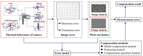
A typical digital camera system widely used in photo mechanics measurements is mainly composed of a camera case, mount, lens, CCD focal plane, and mechanical device used to fasten the camera. Once the camera system starts operating, the heat transfer caused by the coupling effect of its self-heating and the environmental temperature will lead to temperature variations and further generate thermal behaviours of the previously mentioned components. The thermal behaviours that may cause image errors are presented in Figure 1. These thermal behaviours include the rotation ( A X c , A Y c , and A Z c ) and deformation ( δ Z c ) of the camera case, deformation ( δ Z m ) of the mount, deformation ( δ Z l ) of the lens, rotation ( A X C C D , A Y C C D , and A Z C C D ) and translation ( t X C C D , t Y C C D , and t Z C C D ) of the CCD focal plane relative to the camera case as well as the deformation ( δ X C C D and δ Y C C D ) of the CCD itself and the translation ( t Y c ) of the whole camera system induced by thermal deformation of the fixation device.
Figure 2 exhibits the imaging light path of one point in space before and after the above mentioned thermal behaviours occur. Before the thermal behaviours occur, based on the center perspective projection model, the quantitative relationship between the coordinates ( X W P , Y W P , and Z W P ) of a space point P in the world coordinate system (OW-XWYWZW) and its coordinates ( x s p , y s p ) in the pixel coordinate system (os-xsys) can be expressed as:
[ x s p y s p 1 ] = 1 Z C P [ v d x 0 C x 0 v d y C y 0 0 1 ] ( R [ X W P Y W P Z W P ] + T )
where R and T are the rotation matrix and translation vector between the world coordinate system (OW-XWYWZW) and the camera coordinate system (OC-XCYCZC), respectively. Cx and Cy are the coordinates of the principal point in the image pixel coordinate system (os-xsys), dx and dy denote the physical size of one pixel along the xs and ys directions, respectively, v is the image distance, and Z C P is the Z-directional coordinate of the space point P in the camera coordinate system (OC-XCYCZC).
The thermal behaviours ( δ Z c , A X c , A Y c , A Z c , t Y c , δ Z m , and δ Z l ) of the camera case, mount, and lens cause the variation in the space position and orientation of the camera coordinate system (OC-XCYCZC), which changes into (OC′-XC′YC′ZC′), relative to the world coordinate system (OW-XWYWZW). The thermal behaviours ( A X C C D , A Y C C D , A Z C C D , t X C C D , t Y C C D , t Z C C D , δ X C C D , δ Y C C D , δ Z m , and δ Z l ) of the CCD focal plane, mount, and lens lead to the variation in the position and orientation of the changed physics image coordinate system (Os′-Xs′Ys′Zs′), which changes into (Os″-Xs″Ys″Zs″) relative to the changed camera coordinate system (OC′-XC′YC′ZC′). Based on the quantitative geometric analysis of the spatial position and orientation variation of these coordinate systems induced by the previously mentioned thermal behaviours, the coordinates ( X s O , Y s O , Z s O ) and ( X s P , Y s P , Z s P ) of the changed equivalent optical center O and space point P are acquired in the changed physics image coordinate system (Os″-Xs″Ys″Zs″). Furthermore, point p″ at which line P O ¯ intersects plane Xs″Os″Ys″ is the image point corresponding to the space point P after the thermal behaviours occur. Equation (2) expresses the relationship between the world coordinates ( X W P , Y W P , Z W P ) of the space point P and the pixel coordinates ( x s p , y s p ) of the corresponding image point.
[ x s p y s p 1 ] = 1 Z s P Z s O [ 1 d x 0 C x 0 1 d y C y 0 0 1 ] [ Z s P 0 X s P 0 Z s P Y s P 0 0 1 ] R ( R R [ X W P Y W P Z W P ] + R T + T )
where
[ X s P Y s P Z s P ] = R R R [ X W P Y W P Z W P ] + R [ 0 0 v ] + R R T + R T + T
and
[ X s O Y s O Z s O ] = R [ 0 0 v ] + T
R and T are the rotation matrix and translation vector from the coordinate system Os′-Xs′Ys′Zs′ to Os″-Xs″Ys″Zs″, respectively, expressed as:
R = [ cos ( A Z C C D ) sin ( A Z C C D ) 0 sin ( A Z C C D ) cos ( A Z C C D ) 0 0 0 1 ] [ 1 0 0 0 cos ( A X C C D ) sin ( A X C C D ) 0 sin ( A X C C D ) cos ( A X C C D ) ] [ cos ( A Y C C D ) 0 sin ( A Y C C D ) 0 1 0 sin ( A Y C C D ) 0 cos ( A Y C C D ) ]
and
T = [ t X C C D t Y C C D t Z C C D ]
R and T are the rotation matrix and translation vector from the coordinate system OC-XCYCZC to OC′-XC′YC′ZC′, respectively, and expressed as:
R = [ cos ( A Z c ) sin ( A Z c ) 0 sin ( A Z c ) cos ( A Z c ) 0 0 0 1 ] [ 1 0 0 0 cos ( A X c ) sin ( A X c ) 0 sin ( A X c ) cos ( A X c ) ] [ cos ( A Y c ) 0 sin ( A Y c ) 0 1 0 sin ( A Y c ) 0 cos ( A Y c ) ]
and
T = [ L 2 sin ( A Z C ) L 1 sin ( A Y C ) L 2 sin ( A Z C ) sin ( A Z C 2 ) cos ( A Z C 2 ) + ( L 1 ) 2 + ( L 2 ) 2 sin ( A X C ) cos ( π 2 arctan ( L 1 L 2 ) + A X C 2 ) cos ( A X C 2 ) t Y C ( L 1 ) 2 + ( L 2 ) 2 sin ( A X C ) sin ( π 2 arctan ( L 1 L 2 ) + A X C 2 ) cos ( A X C 2 ) + L 1 sin ( A Y C ) sin ( A Y C 2 ) cos ( A Y C 2 ) δ Z c δ Z m δ Z l ]
v′ is expressed as:
v = v + δ Z m + δ Z l
dx′ and dy′ are the physical sizes of one pixel after the thermal behaviours occurred and are expressed as:
d x = δ X C C D + l x l x d x d y = δ Y C C D + l y l y d y
where lx and ly are the initial physical lengths of the CCD focal plane along two directions.
Combined with Equations (1) and (2), the image error model based on the thermal behaviours was established. Next, the image error generated by each thermal behaviour was simulated, and the forms of image errors are shown in Figure 3. Table 1 lists the corresponding error form for each thermal behaviour.
Figure 4 shows the pixel drift caused by temperature variation in the investigated camera system under real experimental conditions. It can be seen that the actual image error is a combination of the previously mentioned error forms, while the influence degree of each error form is different. The previously mentioned thermal behaviours were studied experimentally and the image errors caused by them were analysed. This was done to eliminate the thermal behaviours that have little influence on image error and simplify the image error model discussed above.

2.2. Development and Verification of the Image Error Model for a Specific Camera System

In this subsection, we discuss the thermal responses of the selected camera system, which consists of an IPX-16M3-L CCD camera and Sigma macro 105-mm F2.8DG lens, to temperature variations. We assess the influence of these thermal responses on image acquisition and develop the specific thermal-induced image error model using the investigated camera system.
Figure 5a shows the experimental arrangement for measuring the responses of the rotations ( A X c , A Y c , and A Z c ) and translation ( δ Z c ) of the camera case to temperature variations under two types of fixed modes, i.e., a simple fixed mode with a single contact point and an improved fixed mode with multiple contact planes. The thermal rotations and translation were measured using a high-precision laser displacement sensor (LDS, LK-H050, precision of ±1 μm) during self-heating of the camera. Meanwhile, the temperature of the camera case was measured using a thermal sensor. The thermal rotations ( A X c , A Y c , and A Z c ) and translation ( δ Z c ) are plotted as a function of the temperature of the camera case in Figure 5b. Compared to the simple fixed mode, the improved fixed mode can effectively eliminate all the thermal rotations and translation of the camera case, and further the adverse influence on image acquisition.
Neither of the two types of fixed modes can eliminate the thermal deformations ( δ Z c , δ Z m , and δ Z l ) of the camera case, mount, and lens along the optical axis. In our previous investigation [14], the thermal responses ( δ Z c , δ Z m , and δ Z l ) of these components of the investigated camera system to temperature variations were measured, as shown in Figure 6.
Under the improved fixed mode, the responses of rotations and translations of the CCD focal plane to the temperature of the camera case were measured during self-heating of the camera, respectively, as shown in Figure 7a,b. The laser displacement sensor was used to measure the displacement of the CCD focal plane at different points shown in Figure 7a to calculate the out-plane rotations ( A X C C D and A Y C C D ) and out-plane translation ( t Z C C D ). To calculate the in-plane rotation ( A Z C C D ) and in-plane translations ( t X C C D and t Y C C D ), the CCD focal plane was imaged using a reached thermal-balance camera, and its position was recognised via a matching algorithm, as shown in Figure 7b. The thermal responses of the CCD focal plane were plotted as a function of the temperature of the camera case, as shown in Figure 7c. The thermal translations ( t X C C D , t Y C C D , and t Z C C D ) of the CCD focal plane vary linearly with the temperature of the camera case and introduce considerable image errors. The thermal rotations ( A X C C D and A Z C C D ) present randomness with variations in the case temperature, and the mean values of these rotations were extremely small and hardly caused image errors. The rotation ( A Y C C D ) presents a significant positive correlation with the case temperature, but the maximum error in the pixel drift caused by the maximum rotation during variations in the case temperature has a magnitude of ~0.001 pixel under normal experimental conditions. This is reasonably negligible compared to the measurement resolution of 1/100 of a pixel in photo mechanics measurements.
The CCD focal plane is generally fabricated using silica-based materials that have a very small thermal expansion coefficient. The thermal expansion coefficient has a magnitude of approximately 10−7 °C−1. Considering that the temperature variation range of the focal plane is of the order of 10 °C, the relative distortion in the captured image induced by the deformations of the CCD focal plane is of the order of 10−6, which will lead to a maximum pixel drift of 0.001 pixels. Take a 1000 by 1000 resolution as an example. Therefore, the influence of the thermal deformations ( δ X C C D and δ Y C C D ) of the CCD focal plane on image acquisition can be neglected.
Combined with the above experimental results as well as theoretical analysis, the thermal behaviours that generate considerable image errors are given in Table 2. One part of the behaviours ( δ Z c , δ Z m , δ Z l , and t Z C C D ) introduced image distortion errors, and another part ( t X C C D and t Y C C D ) introduced image translation errors. Introducing both parts of the thermal behaviours into Equation (2) and combining this with Equation (1), we established the image distortion error model, expressed as:
α e = ( Z C P + v ) ( δ Z c + δ Z m + δ Z l ) Z C P δ Z C C D Z C P v v ( δ Z c + δ Z m + δ Z l ) = ( Z C P + v ) ( λ Z c Δ T c + λ Z m Δ T m + λ Z l Δ T l ) Z C P k Z C C D Δ T c Z C P v v ( λ Z c Δ T c + λ Z m Δ T m + λ Z l Δ T l )
and image translation error model, expressed as:
{ Δ x e = t X C C D d x = k X C C D Δ T c d x Δ y e = t Y C C D d y = k Y C C D Δ T c d y
In this case, λ Z c , λ Z m , and λ Z l are the thermal deformation parameters of the camera case, mount, and lens, respectively. k X C C D , k Y C C D , and k Z C C D are the thermal translation parameters of the CCD focal plane along X, Y, and Z directions, respectively. ΔTc, ΔTm, and ΔTl represent the temperature variations in the camera case, mount, and lens, respectively. These can be calculated as:
{ 1 R 1 ( Δ T i c b Δ T c ) = K 1 d ( Δ T i c b ) d t R 1 ( Δ T i c b Δ T c ) R 2 ( Δ T c Δ T e ) R 3 ( Δ T c Δ T m ) = K 2 d ( Δ T c ) d t R 3 ( Δ T c Δ T m ) R 4 ( Δ T m Δ T e ) R 5 ( Δ T m Δ T l ) = K 3 d ( Δ T m ) d t R 5 ( Δ T m Δ T l ) R 6 ( Δ T l Δ T e ) l = K 4 d ( Δ T l ) d t
This was determined in our previous investigation [14]. Equation (13) expresses the relationship between the environmental temperature, temperature of the camera components, and thermal parameters (R1~R6 and K1~K4). The camera system investigated in this study is the same as that used in an earlier study [14]. Therefore, the previously mentioned thermal parameters should also be the same, which are listed in Table 3.
Next, we carried out an experiment to verify the correctness of these models developed using the investigated camera system. As shown in Figure 8a, the camera system and a planar test pattern of a checkerboard were fixed tightly on the optical platform, and the surrounding temperature of the camera was kept constant during the experiment. Once the camera was switched on, the image of the checkerboard was captured with a frame rate of 1/60 frames per second (fps). Then, the coordinates of the corners in these images were obtained using the Harris algorithm, which can be used to calculate the pixel drift of subsequent images relative to the first captured image as well as further image distortion and translation errors. Using the specific thermal-induced image error models, the theoretical results for the thermal-induced pixel drift, image distortion error, and image translation error were calculated. The results of the experiment are presented in Figure 8b. These results indicate that the image error models established in this study can effectively describe the thermal-induced pixel drift, image distortion error, and image translation error.
For the investigated camera system, we performed a series of experiments to investigate the responses of the thermal behaviours of the camera system to temperature and further obtained specific image error models, which were experimentally verified. In the following subsection, the relationship between the image error and measurement error in photo mechanics measurements is discussed in detail in order to establish the relationship between the temperature and measurement error.

2.3. Relationship between Image Error and Measurement Error

The influences of the investigated image errors on the measurement errors in image analysis and fringe analysis of photo mechanics methods need to be considered, separately. For image analysis, the thermal-induced strain measurement error εe is consistent with the image distortion error αe, and the thermal-induced translation measurement errors t e x and t e y are consistent with the image translation errors Δxe and Δye, respectively. The relationships are expressed as:
{ ε e = α e t e x = Δ x e t e y = Δ y e
In this case, taking the DIC method as an example, the measurement errors in this method induced by the distortion error and translation error of speckle images were investigated. As shown in Figure 9, a speckle image was subjected to longitudinal stretching of 1 × 10³ με and translation of the 1 × 10−1 pixel to obtain a distorted image and translated image. Furthermore, DIC was used to obtain the strain result (1.009 × 10³ με) of the distorted image relative to the initial image and translation result (0.891 × 10−1 pixel) of the translated image relative to the initial image. The results obtained using DIC are consistent with the theoretical values considering the numerical error induced by this method, which indicates that the image error is the same as the measurement error observed in the image analysis methods.
In fringe analysis, the phase is a significant parameter for obtaining mechanical information, such as displacement and strain. The image distortion error (αe) and image translation error (Δxe and Δye) cause phase errors (Δ φ e x and Δ φ e y ), which are expressed as:
{ Δ φ e x = α e α e + 1 φ x Δ φ e y = α e α e + 1 φ y Δ φ e x = n x Δ x e Δ φ e y = n y Δ y e
In this case, φx and φy are the initial phase information. nx and ny are constants related to the period of the fringe. Furthermore, the phase errors introduce measurement errors in fringe analysis methods. In this study, the measurement errors induced by the distortion error and translation error of the fringe image were investigated. A fringe image was subjected to a longitudinal stretching of 1 × 10³ με and translation of 1 × 10−1 pixel, respectively, to obtain a distorted image and translated image, as shown in Figure 10. Then, the phase of these fringe images was analysed to calculate the strain result (1.001 × 10³ με) of the distorted image relative to the initial image and the translation result (0.990 × 10−1 pixel) of the translated image relative to the initial image. The measured results are consistent with the theoretical values considering the numerical error induced by this method.
The above experimental results indicate that the image errors induced by variations in the camera temperature will introduce measurement errors in both image analysis and fringe analysis. Thus, combined with the above discussed thermal-induced image error models, we established the relationship between temperature and measurement errors in photo mechanics methods, which served as the theoretical basis for the temperature compensation methods described in the following section.

3. Temperature Compensation Methods for Photo Mechanics Measurements

In photo mechanics methods, the real mechanical information pertaining to the measured object is coupled with the thermal-induced measurement error during the temperature variation period of a camera. Therefore, to obtain the real result regarding mechanical information (resreal), similar to temperature compensation in resistance strain measurement methods, the thermal-induced measurement error (errtemp) must be eliminated from the direct measurement result (resmeas) of photo mechanics methods, which can be expressed as:
r e s r e a l = r e s m e a s e r r t e m p
Herein, we propose three types of temperature compensation methods as follows. The model compensation method is based on the above investigated error model. The preheating method is based on the self-heating characteristics of the camera and the compensation specimen method. All the methods and their applicability are described in detail and were experimentally verified using the same camera system.

3.1. Model Compensation Method

The model compensation method is based on the error models discussed in Section 2, which clarify the relationship between the environmental temperature and measurement error of photo mechanics methods. Its compensation principle is explained in Figure 11. When using this method to correct measurement results, the responses of the thermal behaviours of camera components to temperature and thermal parameters in Equation (13) need to be calibrated as in the case of the error model discussed earlier. Second, the imaging parameters given in Equation (1) need to be obtained before performing measurements. Then, images of the tested object are captured by the camera system, and the environmental temperature is recorded. Finally, the thermal-induced measurement error calculated using the determined error models is subtracted from the direct results of the images obtained using photo mechanics methods to acquire the corrected results.
In this study, the feasibility of the model compensation method is verified for correcting strain and translation measurement results obtained using the investigated camera system. For strain measurements, the experimental arrangement is shown in Figure 12a. A granite specimen (having a volume of 20 × 20 × 40 mm3) containing speckles and a strain gauge was compressed using the testing machine (WDW-100, at 0.005 mm/min), and the deformation of the specimen was measured by the resistance strain measurement method with temperature compensation. Meanwhile, the images of the granite specimen were captured by the camera system, and the environmental temperature of the region around the camera was recorded using a thermal sensor. Using the environmental temperature, given in Figure 12b, and the determined error model, the strain measurement error was calculated. The direct measurement result was obtained using DIC to analyse the captured speckle images. The corrected result from DIC was calculated by subtracting the strain measurement error from the direct measurement result. The experimental results are shown in Figure 12c, which indicate that this compensation method can correct the strain measurement results obtained using photo mechanics methods.
The experimental layout used for translation measurements is shown in Figure 13a. The checkerboard, a rigid body, was moved along the negative x direction with the motion of the electric translation platform (ZOLIX SC300-2A, at 0.625 μm/min). Meanwhile, the images of the checkerboard were captured by the camera system, and the temperature of the environment around the camera was recorded. Using the environmental temperature, indicated in Figure 13b, and the determined translation error model, the translation measurement error was calculated. The direct measurement result was obtained using the Harris algorithm to analyse the captured images. The corrected result was calculated by subtracting the translation measurement error from the direct measurement result. The reference result for translation was calculated using the motion rate of the electric translation platform, which is equal to 0.0227 pixel/min in the captured images. The experimental results are shown in Figure 13c, which indicate that this compensation method can correct the translation measurement results obtained using photo mechanics methods.

3.2. Preheating Method

For indoor photo mechanics measurements, the environmental temperature is almost stable. In this case, after the self-heating period of the camera, the camera system will reach thermal balance and its temperature will remain constant [4,13,14,15]. Therefore, there will be no thermal-induced image error and, hence, no thermal-induced measurement errors according to the investigated error model.
We conducted an experiment to verify the effectiveness of the preheating method in avoiding the thermal error. The experimental layout is shown in Figure 14a. Once the camera was switched on, the temperature of the camera was measured by a thermal sensor, as shown in Figure 14b. During the whole self-heating period, it is clear that the temperature variation in the camera can be divided into two stages, i.e., heating-up stage and thermal balance stage. In the latter stage, the images of the fixed checkerboard were captured. Using the Harris algorithm, the positions of the corners were recognised. Furthermore, the image distortion and image translation were calculated, respectively, as shown in Figure 14c,d. The image strain is in the range of ±5 με, and the image translation ranges from −0.02 to 0 pixels. These experimental results indicate that the preheating method can effectively avoid a thermal-induced error in measurements obtained at a constant environmental temperature.

3.3. Compensation Specimen Method

The image error forms discussed in Section 2 indicate that the compensation specimen method cannot eliminate all types of measurement errors in photo mechanics measurements. This method requires that the thermal-induced error form of the region in the tested specimen shown in the image is the same as that of the compensation specimen, which depends on the responses of the thermal behaviours of the camera system to temperature variations. For the camera system investigated in this study, the image error form generated because of temperature variations is the same in any region of the captured images. Therefore, the compensation specimen method is suitable for correcting the measurement results obtained via photo mechanics methods when using the investigated camera system. In this case, the compensation specimen method requires that an unloaded specimen is placed on the side of the tested specimen. During photo mechanics measurements, images of both the specimens are simultaneously captured by the camera system. For the tested specimen, the results of photo mechanics measurements contain the real mechanical information and the thermal-induced error. However, for the compensation specimen, the measurement result only represents the thermal-induced error. In particular, for correcting the measurement results of photo mechanics methods, the result of the compensation specimen should be subtracted from the result of the tested specimen. The principle of this method is shown in Figure 15.
Next, the feasibility of the compensation specimen method was verified for correcting the results of photo mechanics measurements. For strain measurements, the experimental arrangement used is shown in Figure 16a. A low-carbon-steel specimen (having a volume of 45 × 45 × 60 mm3) with speckles and a strain gauge was compressed using the testing machine (WDW-100, at 0.005 mm/min). The deformation of the specimen was measured using the resistance strain measurement method with temperature compensation. In addition, an identical specimen with speckles was placed next to the tested one. During the experiment, the images of both specimens were captured by the investigated camera system. The measurement results of both specimens were obtained using the DIC method, as shown in Figure 16b. The corrected result obtained from DIC for the tested specimen was calculated by subtracting the measurement result of the compensation specimen from the measurement result of the tested specimen. The corrected result of the tested specimen aligns well with the result of the strain gauge, shown in Figure 16b, which indicates that this compensation method can correct the strain measurement results obtained using photo mechanics methods.
For translation measurements, the experimental layout is shown in Figure 17a. The tested planar specimen with speckles was moved along the x-direction with the motion of the electric translation platform, and the compensation specimen remained stationary. Furthermore, the images of the tested and compensation specimens were captured by the camera system. Then, using a matching algorithm, the translation of the tested and compensation specimens along the x-direction was tracked and calculated. Furthermore, using the compensation specimen method, the corrected photo mechanics result was obtained. The reference result was calculated using the motion rate of 0.625 μm/min of the electric translation platform, which is equal to 0.0237 pixels/min in the captured images. The experimental results are shown in Figure 17b, which indicate that this compensation method can correct the translation measurement results in photo mechanics methods.

4. Conclusions

When using a camera system sensitive to temperature variations for capturing images and performing measurements in photo mechanics methods, temperature is a significant factor that introduces considerable image errors, which further leads to measurement errors in photo mechanics. These errors must be eliminated or compensated. To address this major problem, in the present work, we first investigated the underlying mechanism of thermal-induced measurement errors in photo mechanics methods and further established a physical model to elucidate the quantitative relationship between temperature and the thermal-induced measurement error. The underlying mechanism indicates that (a) mechanical camera components, which include the camera case, mount, lens, and CCD focal plane, have thermal behaviours for temperature variation. These behaviours consist of thermal deformation, rotation, and translation. (b) In our opinion, these thermal behaviours of the camera components generate slight changes in the image geometry leading to inevitable thermal-induced errors. (c) Using the strategy of improving the camera’s fixed mode, some thermal behaviours can be effectively decreased and even eliminated, which may contribute to enhancement of the measurement accuracy of photo mechanics methods.
Then, based on the investigation of the underlying mechanism, we introduced three types of temperature compensation methods, namely the model compensation method, preheating method, and compensation specimen method. The model compensation method uses the quantitative model established in this study to characterise the relationship between the environmental temperature and the thermal-induced measurement error. By recording the environmental temperature during the experiment, the measurement results of photo mechanics methods can be corrected. The preheating method is suitable for indoor photo mechanics measurements, wherein the environmental temperature remains constant, which leads to a thermal balance of the camera system after the self-heating period and, hence, the elimination of the thermal-induced error. The compensation specimen method requires placing an unloaded specimen, which records the thermal-induced measurement error, next to the tested specimen. Corrected measurement results using photo mechanics methods can be obtained by subtracting the measurement result of the unloaded specimen from the tested one. This method reduces the effective resolution of the images and requires that the image error forms in the region of the tested specimen are the same as that in the region of the compensation specimen. According to the characteristics of a given measurement situation, the appropriate compensation strategy can be selected from the proposed temperature compensation methods. For the measurement situation where environmental temperature changes and high image resolution is required, the recommended strategy is the model compensation method, which requires recording environmental temperature and calibrating the thermal parameters and thermal deformation parameters of the camera system. In some special situations, such as an indoor photo mechanics measurement wherein the environmental temperature is constant, the preheating method is the primary choice if there is enough time to wait for thermal balance for the camera. In addition, for situations where the image resolution is enough and the compensation specimen is easy to prepare, the compensation specimen method is the recommended strategy, which does not consider the environmental temperature change.
Lastly, it should be noted that the mechanical components of different camera systems respond differently to temperature variation, which may result in a slightly different error model whereas this can be obtained by the analysis approach fully illustrated in this paper. Importantly, this work presents an idea of building the quantitative physical relationship between temperature and the thermal-induced measurement error and introduces some effective temperature compensation methods for photo mechanics measurements. All of these investigations contribute to enhance measurement accuracy of photo mechanics using experimental mechanics.

Author Contributions

Conceptualization, Q.M. and S.M. Funding acquisition, Q.M. and S.M. Investigation, S.Z. and H.Z. Methodology, S.Z. Writing—original draft, S.Z. Writing—review & editing, H.Z., Q.M., and S.M. All authors have read and agreed to the published version of the manuscript.

Funding

The National Natural Science Foundation of China [grant numbers 11772053, 11727801, and 11402023], the opening projects from the State Key Laboratory of Earthquake Dynamics [grant number LED2016B02], the Pre-research Joint Fund of Aerospace Science and Technology [grant number 6141B06210202], and the National Key R&D Program of China [grant number 2018YFF0300800] funded this research.

Conflicts of Interest

The authors declare no conflict of interest.

References

  1. Wong, K.W.; Lew, M.; Ke, Y. Experience with two vision systems. Proc. SPIE 1990, 1395, 3–7. [Google Scholar] [CrossRef]
  2. Robson, S.; Clarke, T.A.; Chen, J. Suitability of the Pulnix TM6CN CCD camera for photogrammetric measurement. Proc. SPIE 1993, 2067, 66–77. [Google Scholar] [CrossRef]
  3. Handel, H. Analyzing the influences of camera warm-up effects on image acquisition. ACCV 2007, 4844, 258–268. [Google Scholar] [CrossRef]
  4. Ma, S.P.; Pang, J.Z.; Ma, Q.W. The systematic error in digital image correlation induced by self-heating of a digital camera. Meas. Sci. Technol. 2012, 23, 025403. [Google Scholar] [CrossRef]
  5. Pan, B.; Shi, W.T.; Lubineau, G. The effect of camera temperature variations on stereo-digital image correlation measurements. Appl. Opt. 2015, 54, 10089–10095. [Google Scholar] [CrossRef] [Green Version]
  6. Robson, S.; MacDonald, L.; Kyle, S.; Shortis, M.R. Close range calibration of long focal length lenses in a changing environment. Int. Arch. Photogramm. Remote Sens. Spatial Inf. Sci. 2016, 41, 115–122. [Google Scholar] [CrossRef]
  7. Zhou, H.F.; Zheng, J.F.; Xie, Z.L.; Lu, L.J.; Ni, Y.Q.; Ko, J.M. Temperature effects on vision measurement system in long-term continuous monitoring of displacement. Renew. Energy 2017, 114, 968–983. [Google Scholar] [CrossRef]
  8. Podbreznik, P.; Potocnik, B. Influence of temperature variations on calibrated cameras. Int. J. Comput. Inform. Sci. Eng. 2008, 2, 261–267. [Google Scholar] [CrossRef]
  9. Smith, M.J.; Cope, E. The effects of temperature variation on single-lens-reflex digital camera calibration parameters. Int. Arch. Photogram. Remote Sens. Spat. Inf. Sci. 2010, 38, 554–559. [Google Scholar]
  10. Pan, B.; Yu, L.P.; Wu, D.F. High-accuracy 2D digital image correlation measurements using low-cost imaging lenses: Implementation of a generalized compensation method. Meas. Sci. Technol. 2014, 25, 025001. [Google Scholar] [CrossRef]
  11. Yu, Q.F.; Chao, Z.C.; Jiang, G.W.; Shang, Y.; Fu, S.H.; Liu, X.L.; Zhu, X.W.; Liu, H.B. The effects of temperature variation on videometric measurement and a compensation method. Image Vision Comput. 2014, 32, 1021–1029. [Google Scholar] [CrossRef]
  12. Handel, H. Analyzing the influence of camera temperature on the image acquisition process. Proc. SPIE 2008, 6805 (Suppl. 1), 68050X-68050X-8. [Google Scholar] [CrossRef]
  13. Ma, Q.W.; Ma, S.P. Experimental investigation of the systematic error on photomechanics methods induced by camera self-heating. Opt. Express 2013, 21, 7686–7698. [Google Scholar] [CrossRef] [PubMed]
  14. Ma, S.P.; Zhou, S.C.; Ma, Q.W. Image distortion of working digital camera induced by environmental temperature and camera self-heating. Opt. Lasers Eng. 2019, 115, 67–73. [Google Scholar] [CrossRef]
  15. Dauvin, L.; Drass, H.; Vanzi, L.; Dünner, R.; Torres, M.; Béchet, C.; Boettger, D.; Rojas, F.; Shen, T.C. Optimization of temperature, Targets, and illumination for high precision photogrammetric measurements. IEEE Sens. J. 2018, 18, 1449–1456. [Google Scholar] [CrossRef]
  16. Adamczyk, M.; Liberadzki, P.; Sitnik, R. Temperature compensation method for digital camera in 2D and 3D measurement applications. Sensors 2018, 18, 3685. [Google Scholar] [CrossRef] [PubMed] [Green Version]
  17. Sharpe, W.N. Handbook of Experimental Solid Mechanics; Springer: Boston, MA, USA, 2007. [Google Scholar] [CrossRef]
  18. Petzing, J.N.; Tyrer, J.R. Recent developments and applications in electronic speckle pattern interferometry. J. Strain Anal. Eng. Des. 1998, 33, 153–169. [Google Scholar] [CrossRef]
  19. Post, D.; Han, B.; Ifju, P. High Sensitivity Moiré: Experimental Analysis for Mechanics and Materials; Springer: New York, NY, USA, 1994. [Google Scholar] [CrossRef]
  20. Sutton, M.A.; Orteu, J.J.; Schreier, H. Image Correlation for Shape, Motion and Deformation Measurements, Basic Concepts, Theory and Applications; Springer: New York, NY, USA, 2009. [Google Scholar] [CrossRef]
  21. Pan, B.; Qian, K.M.; Xie, H.M.; Asundi, A. Two-dimensional digital image correlation for in-plane displacement and strain measurement: A review. Meas. Sci. Technol. 2009, 20, 062001–062017. [Google Scholar] [CrossRef]
  22. Wang, X.; Ma, Q.W.; Ma, S.P.; Wang, H.T. A marker locating method based on gray centroid algorithm and its application to displacement and strain measurement. Proc. ICICTA 2011, 2, 932–935. [Google Scholar] [CrossRef]
Figure 1. Thermal behaviours of the components in a typical digital camera system used in photo mechanics measurements.
Applsci 10 03422 g001
Figure 2. Imaging light path before and after thermal behaviours occur, wherein L1 and L2 are the Z-directional and Y-directional distance between the rotation center of the camera case and optical center, respectively, and the X-directional distance is assumed to be zero. The rotation center of the CCD focal plane is assumed to be the principal point.
Applsci 10 03422 g002
Figure 3. Different forms of image errors induced by thermal behaviours.
Applsci 10 03422 g003
Figure 4. Pixel drifts under real experimental conditions.
Applsci 10 03422 g004
Figure 5. Experimental investigation of thermal behaviours of the camera case under different fixed modes: (a) schematic of experimental setup, and (b) variation in thermal behaviours with the temperature of the camera case.
Applsci 10 03422 g005aApplsci 10 03422 g005b
Figure 6. Thermal responses of deformations of the camera case, mount, and lens.
Applsci 10 03422 g006
Figure 7. Thermal responses of rotations and translations of the CCD focal plane: (a) experimental arrangement for measuring out-plane thermal behaviours, (b) experimental arrangement for measuring in-plane thermal behaviours, and (c) responses of thermal behaviours to the case temperature.
Applsci 10 03422 g007
Figure 8. Experimental verification of the established image error models: (a) experimental arrangement and (b) experimental results: image drift (multiplied by 200), image distortion error, and image translation error.
Applsci 10 03422 g008aApplsci 10 03422 g008b
Figure 9. Investigation of the relationship between the image error and measurement error of image analysis methods with DIC as an example.
Applsci 10 03422 g009
Figure 10. Investigation of relationship between the image error and measurement error of fringe analysis methods.
Applsci 10 03422 g010
Figure 11. Compensation principle of the model compensation method.
Applsci 10 03422 g011
Figure 12. Experimental verification of model compensation method for compensating strain measurement error: (a) experimental arrangement, (b) environmental temperature during experiment, and (c) experimental results.
Applsci 10 03422 g012
Figure 13. Experimental verification of the model compensation method for compensating the translation measurement error: (a) experimental arrangement, (b) environmental temperature during the experiment, and (c) experimental results.
Applsci 10 03422 g013
Figure 14. Experimental investigation for avoiding thermal-induced error using the preheating method: (a) experimental layout, (b) temperature variation of the camera case, (c) a thermal-induced strain error, and (d) a thermal-induced translation error.
Applsci 10 03422 g014
Figure 15. Principle of the compensation specimen method.
Applsci 10 03422 g015
Figure 16. Experimental verification of the compensation specimen method for compensating the strain measurement error: (a) experimental arrangement, and (b) experimental results.
Applsci 10 03422 g016
Figure 17. Experimental verification of the compensation specimen method for compensating the translation measurement error: (a) experimental arrangement and (b) experimental results.
Applsci 10 03422 g017
Table 1. Error forms corresponding to each thermal behaviour.
ComponentsType of Thermal BehaviourThermal BehavioursType of Image Error
CaseRotation A X c I
A Y c III
A Z c VI
Translation t Y c II
Deformation δ Z c V
CCD focal planeRotation A X C C D VII
A Y C C D VIII
A Z C C D VI
Translation t X C C D IV
t Y C C D II
t Z C C D V
Deformation δ X C C D IX
δ Y C C D X
MountDeformation δ Z m V
LensDeformation δ Z l V
Table 2. Image error types caused by different thermal behaviours.
δ Z c δ Z m δ Z l t Z C C D t X C C D t Y C C D
distortion errortranslation error
Table 3. Thermal parameters of the investigated camera system.
R1R2R3R4R5R6K1K2K3K4
0.1000.0550.1760.0520.0340.0490.9550.0610.8410.718

