Experimental Analysis on Skid Damage of Roller Bearing with the Time-Varying Slip and Temperature Distribution

Abstract
1. Introduction
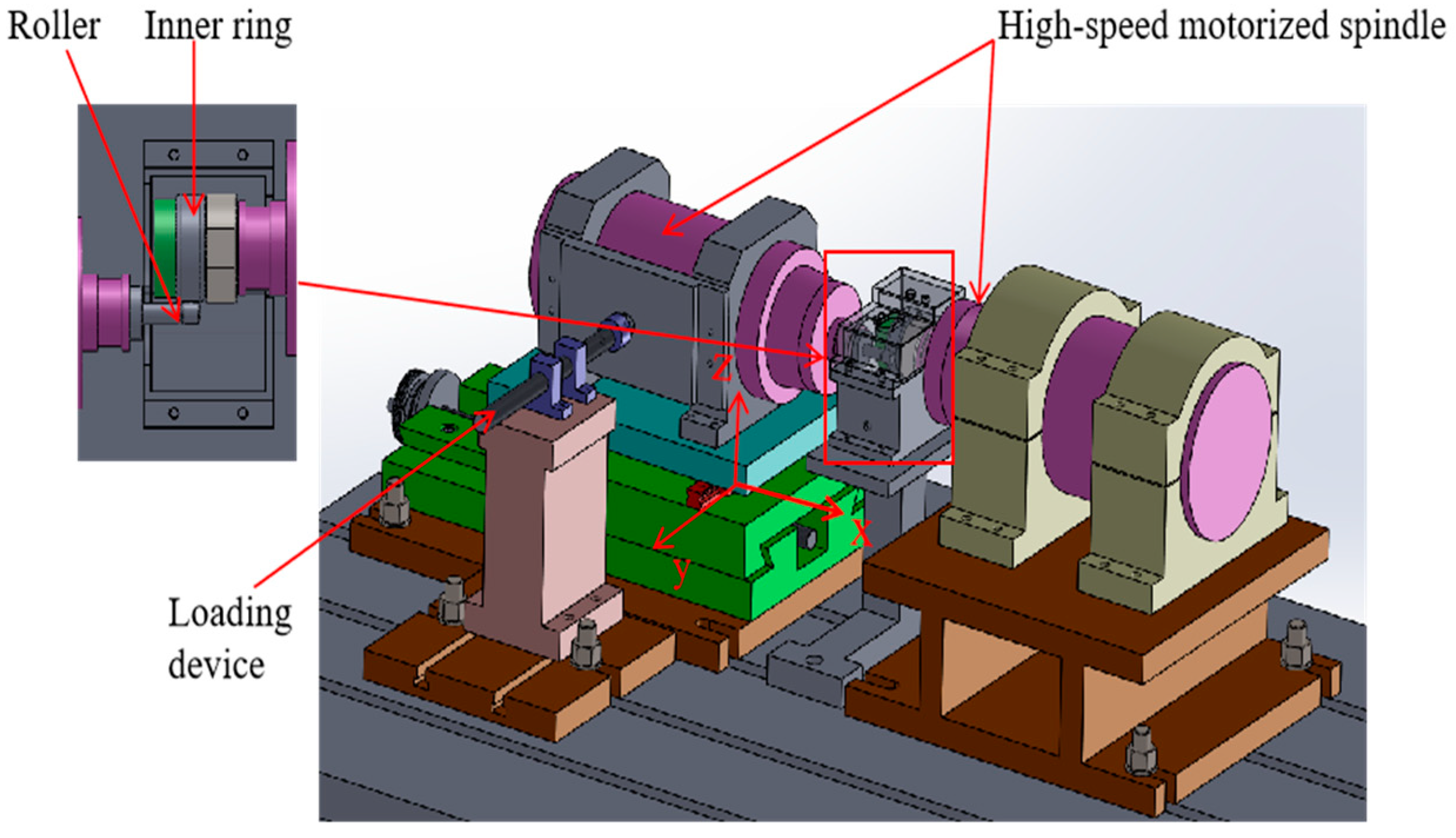
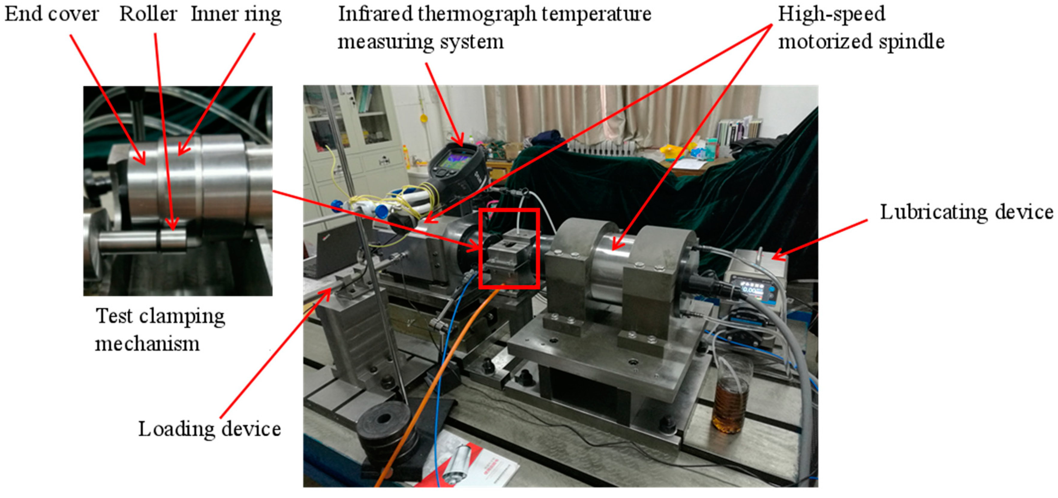
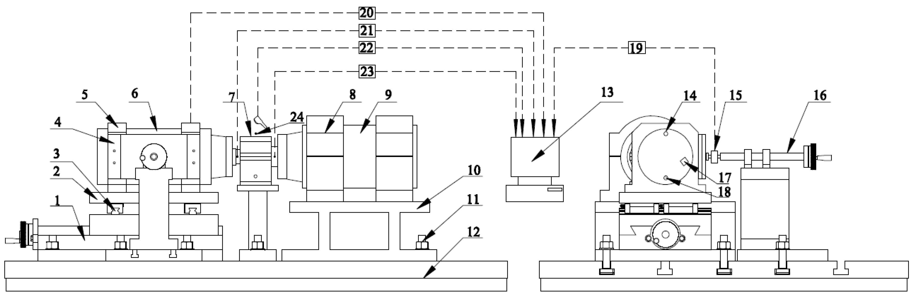
2. Test Rig
2.1. System Composition of the Test Rig
2.1.1. Motorized Spindles
2.1.2. Test Clamping Mechanism
2.1.3. Lubrication and Cooling Device
2.1.4. Loading Device
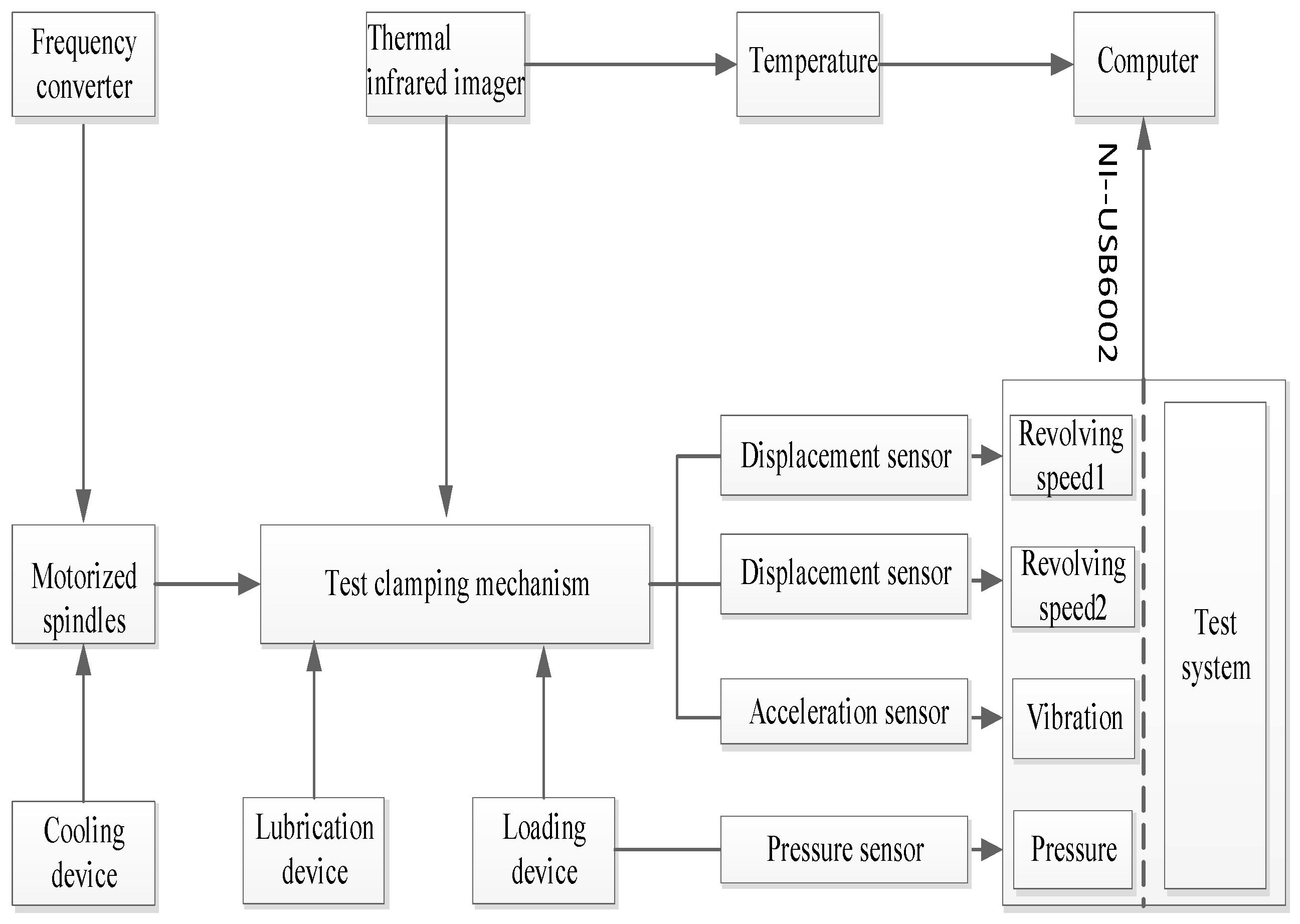
2.1.5. Test System
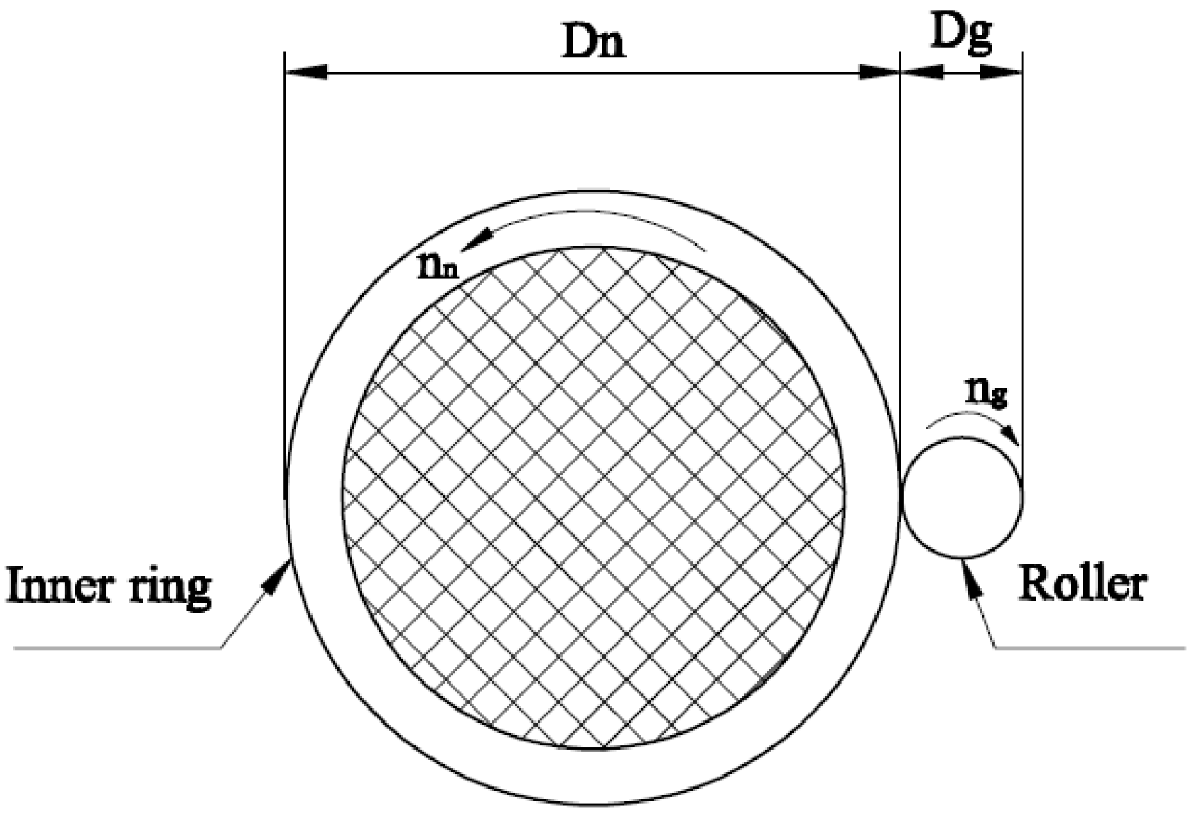
2.2. Work Principle of the Test Rig
3. Results and Discussion
3.1. Experiment Design
3.2. Results and Analysis
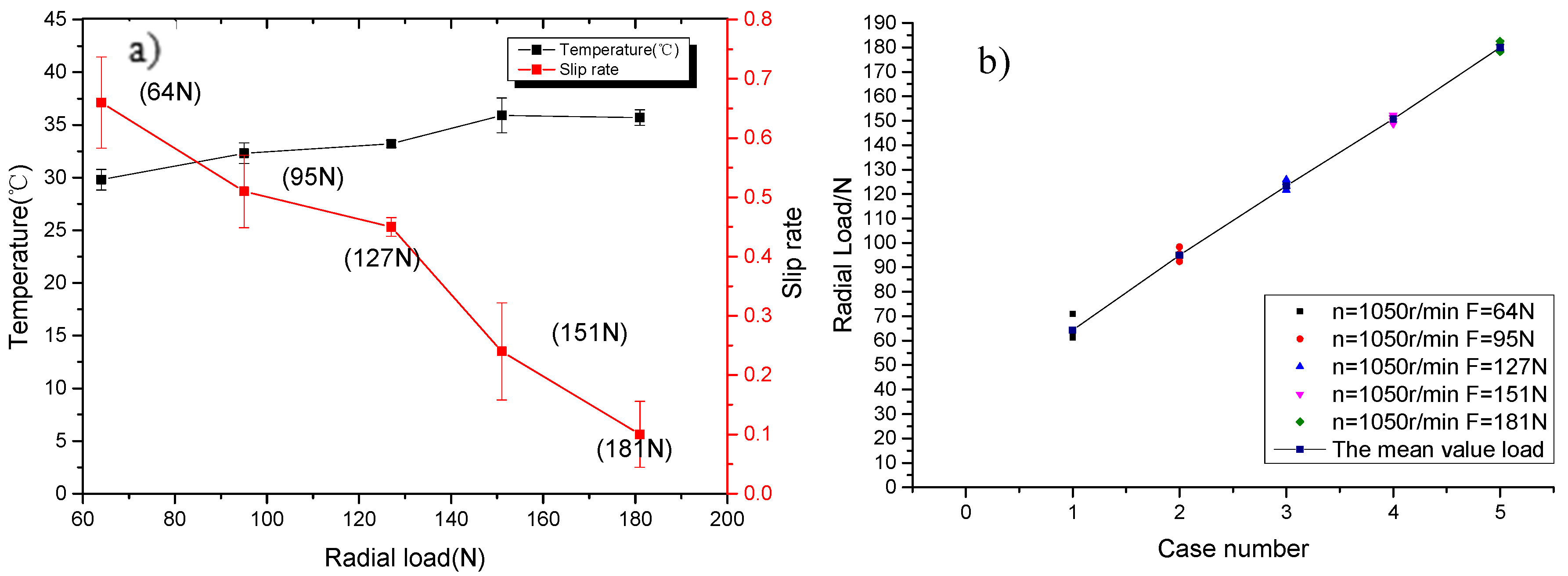
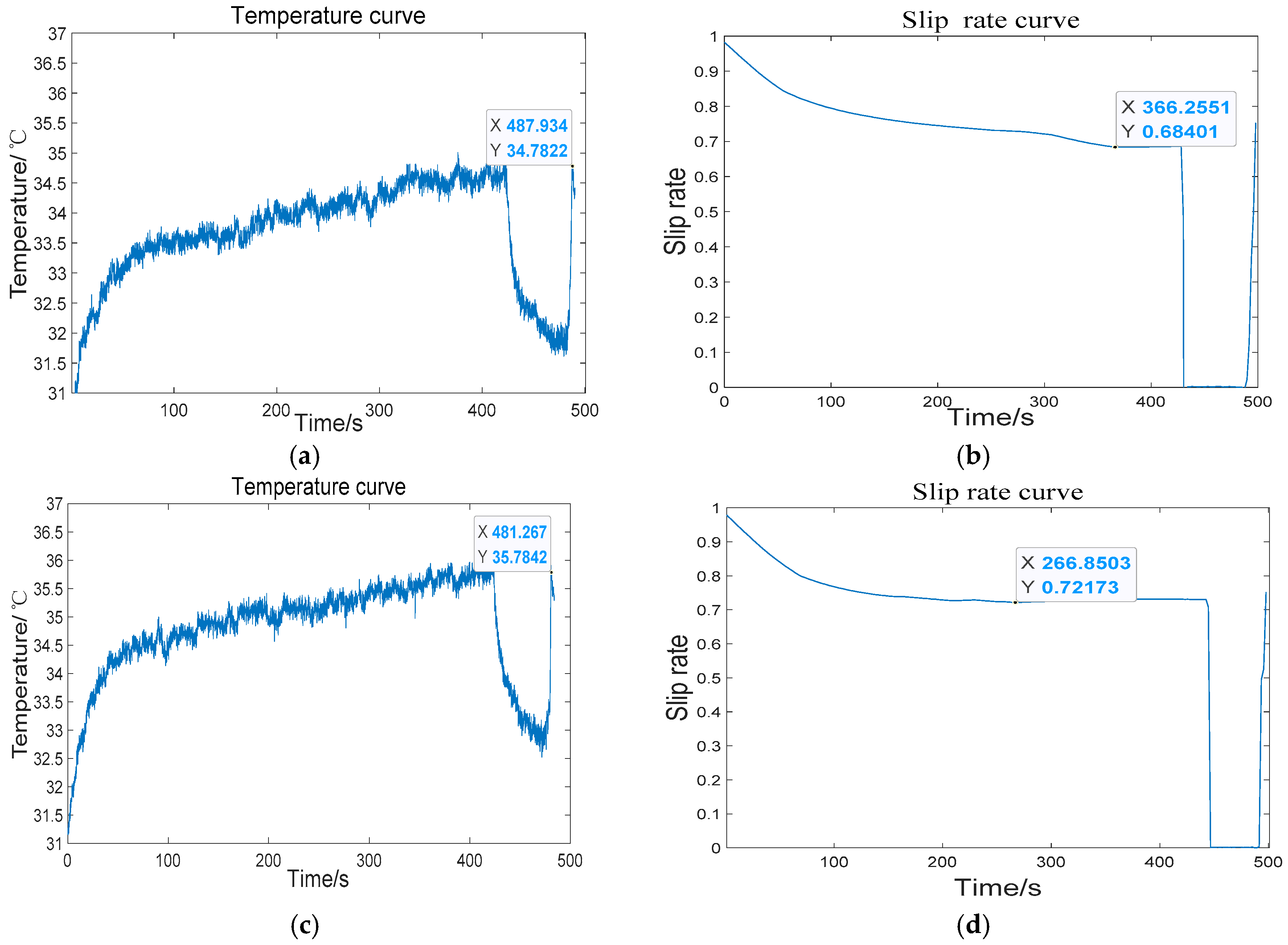
3.2.1. Effect of the Radial Load on the Slip Rate and Temperature
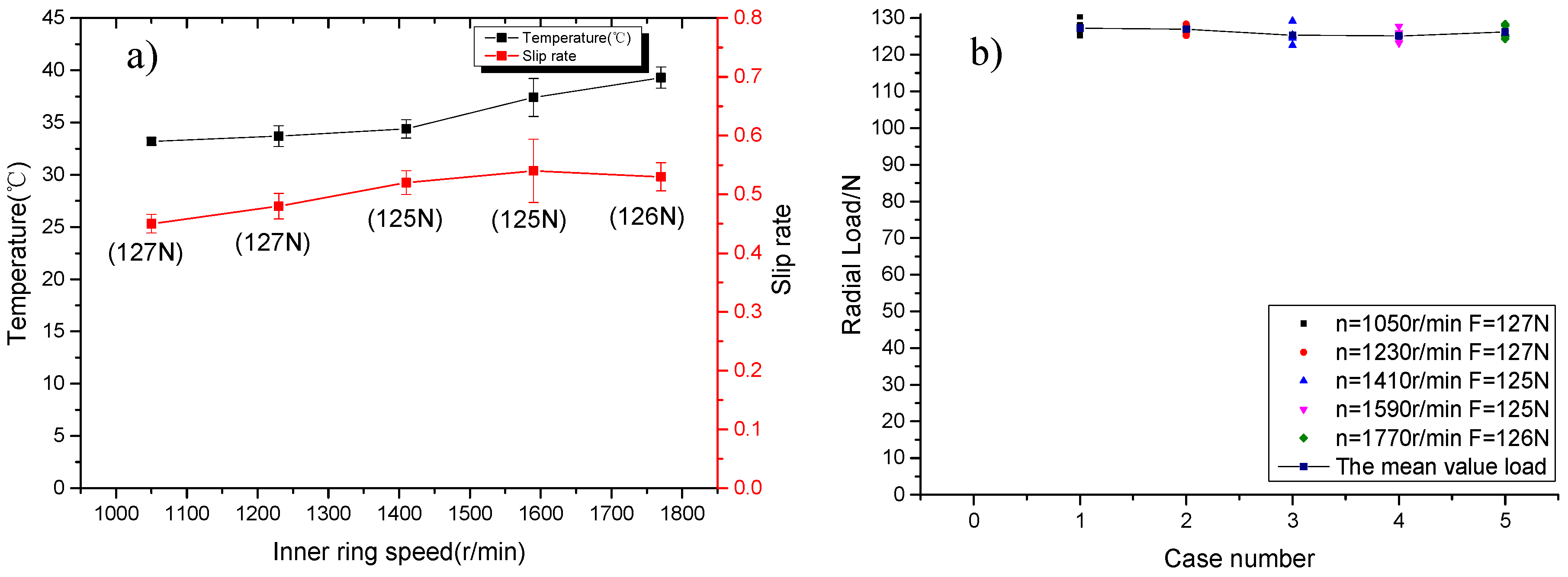
3.2.2. Effect of the Inner Ring Speed on the Slip Rate and Temperature
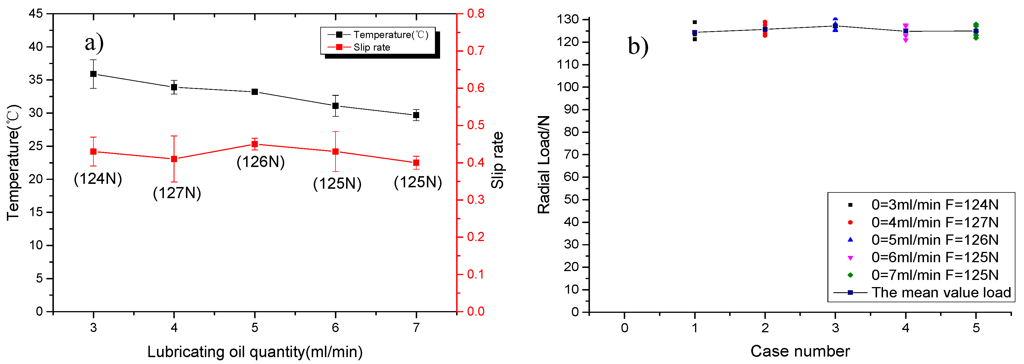
3.2.3. Effect of the Lubricating Oil Quantity on the Slip Rate and Temperature
3.2.4. Effect of the Lubricating Oil Cleanliness on the Slip Rate and Temperature
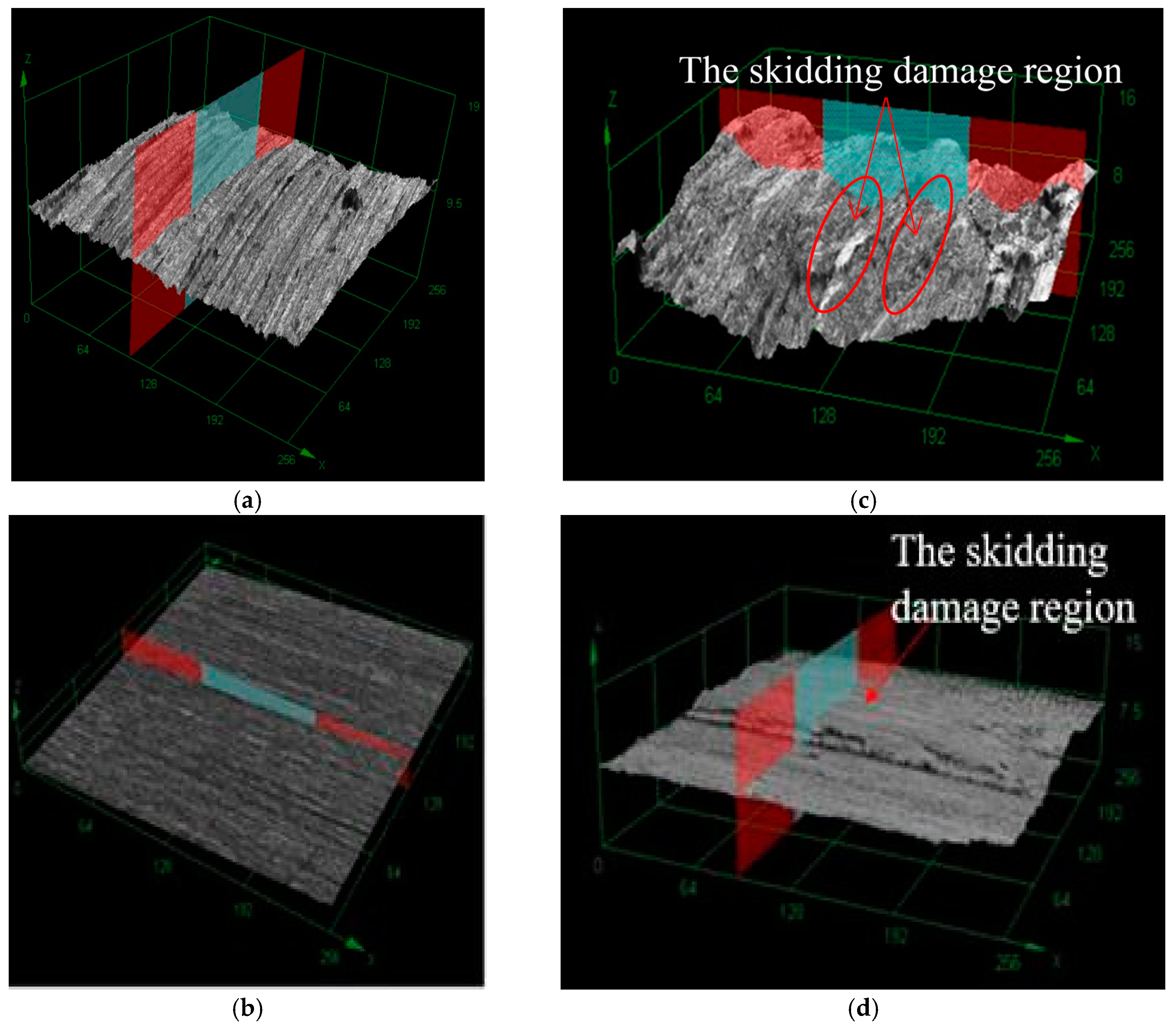
3.2.5. Analysis of the Surface Morphology and the Mechanism of Skidding Damage
4. Conclusions
Author Contributions
Funding
Acknowledgments
Conflicts of Interest
References
- Tassone, B. Roller bearing slip and skidding damage. J. AIRCR 1975, 12, 281–287. [Google Scholar] [CrossRef]
- Asano, K. Recent development in numerical analysis of rolling bearings basic technology series of bearings. KOYO Eng. J. 2002, 160, 65–70. [Google Scholar]
- Jones, A. A general theory for elastically constrained ball and radial roller bearings under arbitrary load and speed conditions. J. Fluid Eng. 1960, 82, 309–320. [Google Scholar] [CrossRef]
- Harris, T. An analytical method to predict skidding in high speed roller bearings. ASLE. Trans. 1966, 9, 229–241. [Google Scholar] [CrossRef]
- Poplawski, J. Slip and cage forces in a high-speed roller bearing. J. Lubr. Technol. 1972, 94, 143–150. [Google Scholar] [CrossRef]
- Rumbarger, J.; Filetti, E.; Gubernick, D. Gas turbine engine mainshaft roller bearing-system analysis. J. Lubr. Technol. 1973, 95, 401–416. [Google Scholar] [CrossRef]
- Walters, C. The dynamics of ball bearings. J. Lubr. Technol. 1971, 93, 1–10. [Google Scholar] [CrossRef]
- Gupta, P. On the geometrical imperfections in cylindrical roller bearings. J. Tribol. 1988, 110, 13–18. [Google Scholar] [CrossRef]
- Gupta, P. On the dynamics of a tapered roller bearing. J. Tribol. 1989, 111, 278–287. [Google Scholar] [CrossRef]
- Wang, Y.-L.; Wang, W.-Z.; Zhang, S.-G.; Zhao, Z.-Q. Investigation of skidding in angular contact ball bearings under high speed. Tribol. Int. 2015, 92, 404–417. [Google Scholar] [CrossRef]
- Takabi, J.; Khonsari, M. On the dynamic performance of roller bearings operating under low rotational speeds with consideration of surface roughness. Tribol. Int. 2015, 86, 62–71. [Google Scholar] [CrossRef]
- Han, Q.; Li, X.; Chu, F. Skidding behavior of cylindrical roller bearings under time-variable load conditions. Int. J. Mech. Sci. 2018, 135, 203–214. [Google Scholar] [CrossRef]
- Tu, W.; Shao, Y.; Mechefske, C. An analytical model to investigate skidding in rolling element bearings during acceleration. J. Mech. Sci. Technol. 2012, 26, 2451–2458. [Google Scholar] [CrossRef]
- Niu, L.; Cao, H.; He, Z.; Li, Y. An investigation on the occurrence of stable cage whirl motions in ball bearings based on dynamic simulations. Tribol. Int. 2016, 103, 12–24. [Google Scholar] [CrossRef]
- Cao, W.; Wang, J.; Pu, W.; Zhang, Y.; Wu, J.; Chu, K.; Wu, H. A study on the effect of acceleration on slip velocity and lubrication performance in cylindrical roller bearings. Proc. Inst. Mech. Eng. Part J J. Eng. Tribol. 2016, 230, 1231–1243. [Google Scholar] [CrossRef]
- Selvaraj, A.; Marappan, R. Experimental analysis of factors influencing the cage slip in cylindrical roller bearing. Int. J. Adv. Manuf. Tech. 2011, 53, 635–644. [Google Scholar] [CrossRef]
- Li, J.; Chen, W.; Xie, Y. Experimental study on skid damage of cylindrical roller bearing considering thermal effect. Proc. Inst. Mech. Eng. Part J J. Eng. Tribol. 2015, 228, 1036–1046. [Google Scholar] [CrossRef]
- Zhang, W.; Chen, W.; Liu, Z. Experimental study on thermal effect of tilted roller pairs in rolling/sliding contacts. Ind. Lubr. Tribol. 2017, 69, 225–233. [Google Scholar] [CrossRef]
- Peng, Y.; Cai, J.; Wu, T.; Cao, G.; Kwok, N.; Zhou, S.; Peng, Z. Online wear characterisation of rolling element bearing using wear particle morphological features. Wear 2019, 430, 369–375. [Google Scholar] [CrossRef]
- Li, J.; Chen, W.; Xue, J.; Han, K.; Wang, Q. Effect of Multiple Factors on Identification and Diagnosis of Skidding Damage in Rolling Bearings under Time-Varying Slip Conditions. Appl. Sci. 2019, 9, 3033. [Google Scholar] [CrossRef]


| Benchmark | Measured Value | Error |
|---|---|---|
| 70 N | 64 N | 8% |
| 100 N | 95 N | 5% |
| 130 N | 127 N | 2% |
| 160 N | 151 N | 5% |
| 190 N | 181 N | 4% |
© 2019 by the authors. Licensee MDPI, Basel, Switzerland. This article is an open access article distributed under the terms and conditions of the Creative Commons Attribution (CC BY) license (http://creativecommons.org/licenses/by/4.0/).
Share and Cite
Li, J.; Xue, J.; Han, K.; Wang, Q.; Chen, W. Experimental Analysis on Skid Damage of Roller Bearing with the Time-Varying Slip and Temperature Distribution. Appl. Sci. 2020, 10, 9. https://doi.org/10.3390/app10010009
Li J, Xue J, Han K, Wang Q, Chen W. Experimental Analysis on Skid Damage of Roller Bearing with the Time-Varying Slip and Temperature Distribution. Applied Sciences. 2020; 10(1):9. https://doi.org/10.3390/app10010009
Chicago/Turabian StyleLi, Junning, Jiafan Xue, Ka Han, Qian Wang, and Wuge Chen. 2020. "Experimental Analysis on Skid Damage of Roller Bearing with the Time-Varying Slip and Temperature Distribution" Applied Sciences 10, no. 1: 9. https://doi.org/10.3390/app10010009
APA StyleLi, J., Xue, J., Han, K., Wang, Q., & Chen, W. (2020). Experimental Analysis on Skid Damage of Roller Bearing with the Time-Varying Slip and Temperature Distribution. Applied Sciences, 10(1), 9. https://doi.org/10.3390/app10010009